JP3810796B2 - Method and apparatus for separating fibrin I from blood plasma - Google Patents
Method and apparatus for separating fibrin I from blood plasma Download PDFInfo
- Publication number
- JP3810796B2 JP3810796B2 JP51910996A JP51910996A JP3810796B2 JP 3810796 B2 JP3810796 B2 JP 3810796B2 JP 51910996 A JP51910996 A JP 51910996A JP 51910996 A JP51910996 A JP 51910996A JP 3810796 B2 JP3810796 B2 JP 3810796B2
- Authority
- JP
- Japan
- Prior art keywords
- chamber
- wall
- plasma
- fibrin
- reaction chamber
- Prior art date
- Legal status (The legal status is an assumption and is not a legal conclusion. Google has not performed a legal analysis and makes no representation as to the accuracy of the status listed.)
- Expired - Fee Related
Links
Images


Classifications
-
- G—PHYSICS
- G01—MEASURING; TESTING
- G01N—INVESTIGATING OR ANALYSING MATERIALS BY DETERMINING THEIR CHEMICAL OR PHYSICAL PROPERTIES
- G01N33/00—Investigating or analysing materials by specific methods not covered by groups G01N1/00 - G01N31/00
- G01N33/48—Biological material, e.g. blood, urine; Haemocytometers
- G01N33/483—Physical analysis of biological material
- G01N33/487—Physical analysis of biological material of liquid biological material
- G01N33/49—Blood
- G01N33/491—Blood by separating the blood components
-
- A—HUMAN NECESSITIES
- A61—MEDICAL OR VETERINARY SCIENCE; HYGIENE
- A61M—DEVICES FOR INTRODUCING MEDIA INTO, OR ONTO, THE BODY; DEVICES FOR TRANSDUCING BODY MEDIA OR FOR TAKING MEDIA FROM THE BODY; DEVICES FOR PRODUCING OR ENDING SLEEP OR STUPOR
- A61M1/00—Suction or pumping devices for medical purposes; Devices for carrying-off, for treatment of, or for carrying-over, body-liquids; Drainage systems
- A61M1/36—Other treatment of blood in a by-pass of the natural circulatory system, e.g. temperature adaptation, irradiation ; Extra-corporeal blood circuits
- A61M1/3693—Other treatment of blood in a by-pass of the natural circulatory system, e.g. temperature adaptation, irradiation ; Extra-corporeal blood circuits using separation based on different densities of components, e.g. centrifuging
- A61M1/3696—Other treatment of blood in a by-pass of the natural circulatory system, e.g. temperature adaptation, irradiation ; Extra-corporeal blood circuits using separation based on different densities of components, e.g. centrifuging with means for adding or withdrawing liquid substances during the centrifugation, e.g. continuous centrifugation
-
- B—PERFORMING OPERATIONS; TRANSPORTING
- B01—PHYSICAL OR CHEMICAL PROCESSES OR APPARATUS IN GENERAL
- B01D—SEPARATION
- B01D21/00—Separation of suspended solid particles from liquids by sedimentation
- B01D21/01—Separation of suspended solid particles from liquids by sedimentation using flocculating agents
-
- B—PERFORMING OPERATIONS; TRANSPORTING
- B01—PHYSICAL OR CHEMICAL PROCESSES OR APPARATUS IN GENERAL
- B01D—SEPARATION
- B01D21/00—Separation of suspended solid particles from liquids by sedimentation
- B01D21/02—Settling tanks with single outlets for the separated liquid
- B01D21/08—Settling tanks with single outlets for the separated liquid provided with flocculating compartments
-
- B—PERFORMING OPERATIONS; TRANSPORTING
- B01—PHYSICAL OR CHEMICAL PROCESSES OR APPARATUS IN GENERAL
- B01D—SEPARATION
- B01D21/00—Separation of suspended solid particles from liquids by sedimentation
- B01D21/18—Construction of the scrapers or the driving mechanisms for settling tanks
- B01D21/20—Driving mechanisms
-
- B—PERFORMING OPERATIONS; TRANSPORTING
- B01—PHYSICAL OR CHEMICAL PROCESSES OR APPARATUS IN GENERAL
- B01D—SEPARATION
- B01D21/00—Separation of suspended solid particles from liquids by sedimentation
- B01D21/24—Feed or discharge mechanisms for settling tanks
- B01D21/2405—Feed mechanisms for settling tanks
-
- B—PERFORMING OPERATIONS; TRANSPORTING
- B01—PHYSICAL OR CHEMICAL PROCESSES OR APPARATUS IN GENERAL
- B01D—SEPARATION
- B01D21/00—Separation of suspended solid particles from liquids by sedimentation
- B01D21/26—Separation of sediment aided by centrifugal force or centripetal force
-
- B—PERFORMING OPERATIONS; TRANSPORTING
- B01—PHYSICAL OR CHEMICAL PROCESSES OR APPARATUS IN GENERAL
- B01D—SEPARATION
- B01D21/00—Separation of suspended solid particles from liquids by sedimentation
- B01D21/26—Separation of sediment aided by centrifugal force or centripetal force
- B01D21/262—Separation of sediment aided by centrifugal force or centripetal force by using a centrifuge
-
- B—PERFORMING OPERATIONS; TRANSPORTING
- B04—CENTRIFUGAL APPARATUS OR MACHINES FOR CARRYING-OUT PHYSICAL OR CHEMICAL PROCESSES
- B04B—CENTRIFUGES
- B04B5/00—Other centrifuges
- B04B5/04—Radial chamber apparatus for separating predominantly liquid mixtures, e.g. butyrometers
- B04B5/0442—Radial chamber apparatus for separating predominantly liquid mixtures, e.g. butyrometers with means for adding or withdrawing liquid substances during the centrifugation, e.g. continuous centrifugation
-
- A—HUMAN NECESSITIES
- A61—MEDICAL OR VETERINARY SCIENCE; HYGIENE
- A61M—DEVICES FOR INTRODUCING MEDIA INTO, OR ONTO, THE BODY; DEVICES FOR TRANSDUCING BODY MEDIA OR FOR TAKING MEDIA FROM THE BODY; DEVICES FOR PRODUCING OR ENDING SLEEP OR STUPOR
- A61M2202/00—Special media to be introduced, removed or treated
- A61M2202/04—Liquids
- A61M2202/0413—Blood
- A61M2202/0415—Plasma
-
- A—HUMAN NECESSITIES
- A61—MEDICAL OR VETERINARY SCIENCE; HYGIENE
- A61M—DEVICES FOR INTRODUCING MEDIA INTO, OR ONTO, THE BODY; DEVICES FOR TRANSDUCING BODY MEDIA OR FOR TAKING MEDIA FROM THE BODY; DEVICES FOR PRODUCING OR ENDING SLEEP OR STUPOR
- A61M2202/00—Special media to be introduced, removed or treated
- A61M2202/04—Liquids
- A61M2202/0413—Blood
- A61M2202/0445—Proteins
- A61M2202/0447—Glycoproteins
- A61M2202/0449—Fibrinogen, also called factor 1
-
- A—HUMAN NECESSITIES
- A61—MEDICAL OR VETERINARY SCIENCE; HYGIENE
- A61M—DEVICES FOR INTRODUCING MEDIA INTO, OR ONTO, THE BODY; DEVICES FOR TRANSDUCING BODY MEDIA OR FOR TAKING MEDIA FROM THE BODY; DEVICES FOR PRODUCING OR ENDING SLEEP OR STUPOR
- A61M2202/00—Special media to be introduced, removed or treated
- A61M2202/04—Liquids
- A61M2202/0413—Blood
- A61M2202/0445—Proteins
- A61M2202/0447—Glycoproteins
- A61M2202/045—Fibrin
-
- B—PERFORMING OPERATIONS; TRANSPORTING
- B01—PHYSICAL OR CHEMICAL PROCESSES OR APPARATUS IN GENERAL
- B01D—SEPARATION
- B01D2221/00—Applications of separation devices
- B01D2221/10—Separation devices for use in medical, pharmaceutical or laboratory applications, e.g. separating amalgam from dental treatment residues
-
- B—PERFORMING OPERATIONS; TRANSPORTING
- B04—CENTRIFUGAL APPARATUS OR MACHINES FOR CARRYING-OUT PHYSICAL OR CHEMICAL PROCESSES
- B04B—CENTRIFUGES
- B04B5/00—Other centrifuges
- B04B5/04—Radial chamber apparatus for separating predominantly liquid mixtures, e.g. butyrometers
- B04B5/0442—Radial chamber apparatus for separating predominantly liquid mixtures, e.g. butyrometers with means for adding or withdrawing liquid substances during the centrifugation, e.g. continuous centrifugation
- B04B2005/0485—Radial chamber apparatus for separating predominantly liquid mixtures, e.g. butyrometers with means for adding or withdrawing liquid substances during the centrifugation, e.g. continuous centrifugation with a displaceable piston in the centrifuge chamber
-
- Y—GENERAL TAGGING OF NEW TECHNOLOGICAL DEVELOPMENTS; GENERAL TAGGING OF CROSS-SECTIONAL TECHNOLOGIES SPANNING OVER SEVERAL SECTIONS OF THE IPC; TECHNICAL SUBJECTS COVERED BY FORMER USPC CROSS-REFERENCE ART COLLECTIONS [XRACs] AND DIGESTS
- Y10—TECHNICAL SUBJECTS COVERED BY FORMER USPC
- Y10T—TECHNICAL SUBJECTS COVERED BY FORMER US CLASSIFICATION
- Y10T436/00—Chemistry: analytical and immunological testing
- Y10T436/11—Automated chemical analysis
- Y10T436/111666—Utilizing a centrifuge or compartmented rotor
-
- Y—GENERAL TAGGING OF NEW TECHNOLOGICAL DEVELOPMENTS; GENERAL TAGGING OF CROSS-SECTIONAL TECHNOLOGIES SPANNING OVER SEVERAL SECTIONS OF THE IPC; TECHNICAL SUBJECTS COVERED BY FORMER USPC CROSS-REFERENCE ART COLLECTIONS [XRACs] AND DIGESTS
- Y10—TECHNICAL SUBJECTS COVERED BY FORMER USPC
- Y10T—TECHNICAL SUBJECTS COVERED BY FORMER US CLASSIFICATION
- Y10T436/00—Chemistry: analytical and immunological testing
- Y10T436/25—Chemistry: analytical and immunological testing including sample preparation
- Y10T436/25375—Liberation or purification of sample or separation of material from a sample [e.g., filtering, centrifuging, etc.]
Abstract
Description
技術分野
本願は、プラスマからフィブリンモノマー等の成分を分離するべく壁によって形成された第2室にプラスマ(血漿)を供給するステップを有する方法に関し、架橋していないフィブリンポリマーを含有している部分は、適当な酵素が添加されている間に分離せしめられる。
背景技術
欧州特許第592,242号公報(EP-PS No.592,242)には、フィブリンモノマーを含有する組成剤(配合剤、コンパウンド)を含む所定箇所に接して当該ステップと同時にこのモノマーをフィブリンポリマーに変換させる全く新規なフィブリンシーラント用の方法及び組成剤が記載されている。この「フィブリン」という用語は、フィブリンIや、フィブリンIIとして、及び/又は、デス(des)ββフィブリンとして定義される。
欧州特許第654 669号公報から、血液からフィブリンモノマー等のコンポーネントを分離するための方法および装置が知られている。種々の特定の重量(重要性、gravities)を有する幾つかのコンポーネントを含む液体の当該コンポーネントを分離するためのこの方法は、血液を装置の第1室(第1チャンバ)内に集めるステップを有している。当該第1室は、実質的に軸対称な外壁と内壁とによって形成されている。装置は当該チャンバの対称軸を中心として回転せしめられ、これによって、その血液は遠心分離作用を受ける。これにより、血液のコンポーネント(成分)とコンポーネントとの間に、同心の界面(インターフェース)が形成される。プラスマ等の血液のコンポーネントの少なくとも1つは、続いて、装置内の第2室(第2チャンバ)に移動(流動)せしめられる。この移動は、好ましくは、装置の遠心分離が継続している間に、第1室の容積を減じることによって行われる。この実質的に軸対称になっている内壁は、第1室内に設けられており、これにより、すべての血液がその分離に必要な遠心分離の回転(の影響)が確実に受けられるようになっている。この内壁の半径は、所望の回転速度に対応するように構成されており、チャンバのあらゆる部位において、同心分離を維持するのに十分な遠心分離力が加えられる。
第2室において、架橋していないフィブリンポリマーを含む部分は、適切な酵素の手段によってプラスマから分離され、続いて、フィブリンモノマーに再分解(redissolved)され、そして、第2室の容積を減じることにより、フィルターを通してシリンジへ移動(流動)せしめられる。
しかしながら、上記タイプの装置における濾過(filtration)の方法のみによっては、たとえば、血液からフィブリンモノマーを分離する等のコンポーネントの分離において満足のいく結果が得られない、ということが判明した。これは、主として、第2室内においてフィブリンモノマーを含んでいる部分について満足のいく分離を保証することが困難であるという事実に基づいている。従って、液体(流体)の部分が、方法の連続ステップ時に第2室から第1室に続いて流動せしめられている間に、フィブリンの比較的大きい血中含有量が失われることになる。
また、初期のファブリンモノマーの方法において、適切な酵素を含んでいプラスマ内のフィブリノーゲンの上記処理により、架橋していないフィブリンポリマーが形成された。このフィブリンポリマーは、第2室の底に厚いゲルの塊の形態をなしている。所望のファブリンモノマー溶液を形成するために、実質的な撹拌剤(アジテーション、agitation)と結合した有意な量の再溶融緩衝剤(再分解緩衝剤、redissolving buffer)が必要とされた。この結果、幾つかの欠点(障害)が生じた。第1に、たとえば欧州特許第529,242号公報に記載されているようなフィブリンシーラントとして用いられるための、好ましいフィブリンモノマーの方法は、濃縮されたフィブリンモノマー溶液と、そのゲル塊を分解(溶解)させるために必要とされる多量の再溶解緩衝剤つまり溶剤(溶媒)とを必要とし、これにより、同じように機能しない希釈溶液が形成された。さらに、このゲル塊をフィブリンモノマー溶液内に溶解させるのに必要とされる実質的な撹拌剤(アジテーション、agitation)は、装置及びフィブリンそのものに損傷を生じさせる可能性がある。
したがって、本発明の目的は、血液からフィブリンモノマーなどの成分を分離する改良方法を提供することである。
本発明は、円筒形の室内において、プラスマ部分から、架橋していないフィブリンポリマーを分離させることが可能な方法を含む。このような分離は、上記架橋していないフィブリンポリマーを上記室(チャンバ)の外壁に付着(沈殿、沈積、堆積、deposit)させる遠心分離時に行われる。上記室内に収集された残留している液体部分(流体部分)は上記室から除去され、実質的に壁に付着した状態でチャンバ内に残留している架橋していないフィブリンポリマーを有する部分は、溶剤の追加および遠心分離による撹拌(遠心分離動作、centrifugal agitation)によって溶解される。
酵素を含むプラスマの処理は連続的に行われる遠心分離の間に行われるので、その結果生じた架橋していないフィブリンポリマーに遠心力が加えられると、実質的に室の周方向壁に付着する薄いゲルフィルムとして凝固せしめられることが可能である。遠心分離が停止されると、残留しているプラスマ液は室の底部に沈殿し、何らかの簡便な手段によって除去される。適当な再溶解(再分解)緩衝剤溶液(redissolving buffer solution)を室内に案内し、遠心分離撹拌に対して緩衝剤をゲルでコーティングされた室内に供給することによって、所望のフィブリンモノマー溶液が得られる。上記方法は従来の方法よりも優れた利点を有する。まず、架橋していないゲルの緩衝剤溶液による再溶解(再分解)については、同じ容量のフィブリンゲルで、従来の方法において準備されるフィブリンゲル塊に比べて、広い表面領域について行うことができる点で、非常に効率的である。このため、ゲルは少量の再溶解緩衝剤に溶解されることが可能となり、その結果、濃縮されたフィブリンモノマー溶液となるので望ましい。さらに、ゲルでコーティングされた室内における、緩衝剤溶液における遠心分離撹拌作用は比較的穏やかな方法であるので、装置やフィブリンモノマー製品に損傷を与えることがない。その結果得られる高濃度のフィブリンモノマー溶液のフィブリンモノマーは、1ml当たり10〜30mgの範囲内にあり、好ましくは約25mg/mlである。
本発明はまた、装置の第1環状室に好ましくは抗凝血剤を含む血液を供給するステップを有する方法を含む。該環状室は円筒外壁および円筒内壁によって形成されており、上記壁はいずれも共通軸を中心とする同軸に延在している。また、上記環状室は上壁と底壁とによって形成されており、上壁あるいは底壁は第1室内で位置を変えられるピストンボデーによって形成される。上記方法はさらに、血液を細胞部分とプラスマ部分とに実質的に分離させ、その後ピストンボデーによる作用を受けている間に、その結果形成されたプラスマ部分を外側円筒壁によって形成された第2室へと移動させるべく、上記共通軸を中心として装置を遠心分離にかけるステップを含む。上記外側円筒壁は上記共通軸と同軸をなし、架橋していないフィブリンポリマーを含む部分が第2室内で分離せしめられる一方で、適当な酵素が追加される。本発明では、上記方法は、遠心分離の間、フィブリノーゲンを含むプラスマ部分には酵素が加えられ、その結果、上記第2室の円筒外壁には架橋していないフィブリンポリマーが付着することを特徴とする。第2室の底部に収集された液体部分は、ピストンボデーによる作用を受ける間に第1室へと移動させられる。実質的には円筒壁に付着した状態で第2室内に残留している架橋していないフィブリンポリマーは、溶剤の追加および遠心分離撹拌によって溶解(分解)される。この後、酵素が除去され、必要であれば、上記のように形成されたフィブリンモノマー溶液は、何らかの望ましい収容容器へと移動せしめられる。
したがって、溶液を収集するための殺菌状態が容易に維持される。フィブリンモノマーは、再溶解された後に、従来技術において説明したようなさらなる利用のために、シリンジなどの収容容器へと移動(流動)せしめられる。移動の前に、酵素を何らかの簡便な手段によって除去することも可能である。
回転の中央軸の周囲で遠心分離を行うことによって液体から成分を分離させる装置は、外側円筒壁および内側円筒壁によって形成された第1環状室を備え、上記壁はいずれも上記回転軸について同心円上となるようにされている。上記第1環状室は上壁および底壁によって形成されており、底壁は上記第1室内で位置を変えることが可能なピストンボデーによって形成される。上記装置は、第1導管を介して第1室と連通する第2室をさらに備えており、上記第2室は、回転軸について同心円上となるように形成された外側円筒壁と、上記ピストンロッドと、底壁とによって形成されている。上記第2室は、遠心分離の間は第1室の下方に配置されるように構成されている。上記装置はまた、血液を第1室に供給する血液供給手段と、分離を促進する配合物を供給する配合物供給手段と、少なくとも1つの液体収容容器の接続部を収容する収容手段とをさらに備えている。上記収容手段は第2導管を介して第2室と連通している。好ましい実施形態では、ピストンロッドは第1室の内壁を構成している。
本発明に係る方法を実施するための本願の装置は、第1室の上壁にある開口と第2室の底壁にある開口との間に延在する溝を少なくとも1つは備えていることを特徴とする。
この結果、比較的単純な装置であって、問題の部分を一方の室から他方の室へと容易かつ速やかに流動させることがピストンの位置と独立して可能である装置が提供される。このことは特に、フィブリン Iを含む部分を分離した後、液体部分を第2室から第1室に移動させることについて当てはまる。後者は特に、遠心分離装置が停止したときに、液体は自動的に第2室の底部に濃縮されているためであって、液体は、例えば、液体を流動溝を上方に移動させるべく第2室内の圧縮空気により作動するピストンによって、第1室へと容易に移動させることができる。
本発明においては、上記溝は、第1室および第2室の外側円筒壁のいずれの内側に延在するとよく、その結果、装置の製造は特に単純で容易となる。
本発明においては、1つ以上の溝の開口は、好ましくは、底壁によって形成される凹部に関連して、室の中央部に設けられている。その結果、問題の液体部分は、直接、溝の入口開口へと容易かつ速やかに案内される。
さらに、あるいは本発明においては、各溝(チャネル)はパイプ(管路)によって形成されており、該パイプは、ピストンボデーを通って直線状に延在しており、パイプは、第1室の上壁および第2室の底壁のそれぞれの端部に設けられており、それは、各チャンバの端部における溝部(チャネル部)に連絡(連通)している。
本発明においては、第1室および第2室は、特に単純な方法では、外側および内側のシリンダによって形成された共通の外側円筒壁を備えている。該シリンダは、互いに密閉状対で適合せしめられており、また、その間に軸方向に延在する溝が形成されている。該シリンダの端部は、ピストンボデーに接続されたピストンロッドの通路となり得る開口を備えた端壁によって形成されることができる。上記ピストンボデーは、第1室の底壁を形成し、上記第1室を第2室と分離させている。上記溝は、シリンダの端壁間で、ピストンロッドに近接している開口へと延在している。
上述したように、本発明の方法は、個々の血液成分(コンポーネント)や、そのような成分を含む溶液を分離したり隔離したりするための改良型プロセスに関する。しかしながら、この方法は、円筒形状の遠心分離装置に適用可能なあらゆる処理(処置)にふさわしい。そこにおいて、第1溶液は、遠心分離時に、触媒、或いは試薬、を以て取り扱われ、溶液は、所望の製品の中間的な形態で、遠心分離装置の壁に付着する。この中間的な形態の物質は、適当な再溶解溶液を用いて、遠心分離撹拌によって再溶解が行われ、上記再溶解溶液内において、所望の濃度の製品を構成する。本明細書に記載されている方法は、第1溶液を他方の溶液から、すなわちプラスマを血液全体から、遠心分離することを含んでいてもよい。他の血液処理(処置、procedure)は、そのような方法から利益を受けることが可能であるが、当該血液処理は、多血小板プラスマや、血小板濃縮物、クリオプレシピテートフィブリノーゲン(cryoprecipitated fibrinogen)や、トロンビン等のプラスマ内に含まれる他のタンパク質や、フィブロネクチン等のいずれかの血液成分の分離に限定されるものではない。好ましくは、その血液は、単一の供血者(ドナー)からのものであり、最も好ましくは、その血液は、その血液成分(コンポーネント)が施されるであろう同一の者からのものである。
この方法は、これ以降、フィブリンモノマー溶液の形成について記載され、一方、本発明の視野は、当該技術に精通した者には理解されるであろうように、それに限定されるべきものではない。
ここに用いられるように、「遠心分離動作(遠心分離による撹拌、centrifugalagitation)」という用語は、本装置の動作について言及される。この装置において、再溶解緩衝剤溶液(再分解緩衝剤溶液、redissolving buffer solution)は、架橋していないフィブリンポリマーゲル等の中間生成物(intermediate product)を再溶解(再分解)するために、上記外チャンバ壁から案内される。そのような動作や、遠心分離動作は、ゲルのすべての露出面積が上記再溶解する溶液に影響されるようにすることを保証するべく遠心分離を含むことができ、また、好ましくは、同一方向に停止したり開始したりする回転を伴ったり、そして/あるいは、逆方向に停止したり開始したりする回転を伴ったりするような遠心分離を含む。典型的な遠心分離動作は、これに限定されるものではないが、あらゆる所望の時間長さ、繰り返される正逆サイクルで2000〜5000RPMで、5〜30秒間回転させること、好ましくは、5〜10秒間回転させることを含む。この方法において、1〜2分間、繰り返される正逆サイクルで約3000RPMで、5〜10秒間回転させることが好ましい。上記の如く、これは、その溶剤を初期に分配するために、たとえば、20秒間、又はそれ以上の間、やや、より遅い回転の後に行うことができる。
ここで用いている「フィブリン」という用語は、フィブリンI、フィブリンIIや、デス(des)ββフィブリンに言及したものである。
上述したように、本願の装置は、液体を装置の上記第2室の底部から第1室へと移動させるための溝を少なくとも1つ備えている。この特徴は、本発明の好ましい方法を提供するにあたっての明白な利点になっている。従来の上記装置および方法では、架橋していないフィブリンポリマーゲル塊を形成するときに、ピストンプレートおよび第1室内に延在する導管を通して、残留しているプラスマ液を上方に移動させることができるように、ピストンを押し下げる必要があった。従来の方法では、ピストンを液体に接触させねばならない。本願の方法においては、ゲルは第2室の壁に付着しているので、残留しているプラスマ流体に接触するほどピストンを押し下げることはできない。第2室の底部から第1室へと延在する溝を形成し、第2室に気体の入口(大気の入口、atomospheric inlet)を形成することによって、ピストンはわずかに押し下げられ、プラスマ液(流体)を溝の上方および第1室内に移動させるのに十分な圧力を加えることか可能となる。上述したように、室(チャンバ)全体、すなわち外壁全体に延在する1つ以上の溝を形成することが可能である。外壁に溝を形成する好ましい方法は、一方のシリンダが他方のシリンダを密封すべく収められる2つのシリンダよりなる装置を構成することである。外側シリンダの内側、あるいは内側シリンダの外側に、1つ以上の溝を形成することによって、1つ以上の溝が形成される。
本願の装置は、血液全体を所望の血液成分、好ましくは、例えばシーラントとして有用な自系成分(autologous component)に変えることが可能な、単一の閉鎖された自動装置である。
上記装置は、装置を取り付けて位置合わせをし装置を軸の周囲で必要に応じて回転させピストンおよび押圧ロッドを作動させることが可能なドライブユニット内で用いるのに便利である。上記押圧ロッドは、以下の記載から、ピストンの移動を容易にするものであることがわかるであろう。
【図面の簡単な説明】
本願装置及び本願方法の好ましい実施形態を、図面を参照しながら記載する。
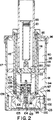
図1は、本願発明の好ましい第1実施形態の軸方向断面図である。
図2は、本願発明の好ましい第2実施形態の軸方向断面図である。
図3は、本願発明の好ましい第3実施形態である。
本願発明の好ましい実施形態の記載
本願発明の図1の装置は、実質的に回転対称である部分から構成されており、当該部分は、この装置が中心軸1を中心として遠心分離されるようにそれ自体は周知の容易な方法で、遠心分離装置内に設けられることができることを示している。この図1において、好ましい実施形態の装置は、外容器2と内容器3とが互いに完全にフィット(適合)すると共に軸方向に延在する中間溝4が形成されている部分を除くあらゆる箇所において互いに密に接するような状態で外容器2と内容器3とを備えている。この溝4は、内容器3に構成されている溝により形成されている。この2つの容器2,3は、夫々、上部分5,6を備えている、当該上部分5,6は、ピストン・ロッド8を通過させることができる中央開口7を有している。この中央開口7の周囲に、当該2つの容器は、軸方向に延在する部分9,10を夫々備えている。当該部分9,10は、中空になっているピストン・ロッド8に近接して、容器の内側から離れる方向に延在している。上記外容器2は、径方向に短く突出しているフランジ11に沿って、この中空ピストン・ロッドに接している。この径方向突出フランジ11は、シール・リング13を受け入れる凹部12を備えている。
図1に示すように、上記溝4は、内容器と外容器の円筒壁から上記上部分5,6及び上記軸方向延在部分9,10を通って開口7の上記シール・リング13のすぐ下に位置する開口に至るように、内容器と外容器との間に延在している。上記内容器3の軸部分10は、開口7に接している。当該軸部分10は、上記中空のピストン・ロッド8を中心とする狭くはあるが動きに制約のない通路が容器2,3の内側に延在するように寸法構成されている。
この外容器2は、直径が同一である円筒部を備えている(図1を参照)。この部分は、この図の下方向に示されるように、切頭円錐形(frusto-conical)の内面16をなしている変形部15を通して直径が僅かに大きくなっている円筒部に続いている。この内容器3の端部は、外容器2の上記変形部15の直径が大きくなっている上記円筒部14に続く位置に位置している。内容器3の下側端部は、切頭円錐形の外面17を備えている。この切頭円錐形は、外容器2の内側に位置している切頭円錐形の内面16の形状に適合(マッチング)している。外環状ディスク19と内環状ディスク20が、夫々、内容器3の底端部の直下に設けられている。この内容器3の底端部は、径方向面(半径面、放射面、radial surface)18を有している。これらのディスクは、互いに近接して接している。しかし、当該ディスクは、それらの間に溝21を形成している。この溝21は、中央開口22から軸方向面(の方向)に延在すると共に、外容器2の内側まで延在している。溝21は、軸方向延在部23を通って、外容器2と内容器3との間に位置している上記溝4に連通している。溝21と軸方向溝部23とは、外ディスク19に対向する内ディスク20の側に形成された溝手段によって適切に形成されている。これらの2つのディスク19,20は、図1に示す如く、これらが実質的に切頭円錐形内面及び切頭円錐形外面をなすような傾斜をもって形成されている。これらの2つのディスク19,20は、上記中央開口22に向かって下方向に傾斜している。図1は、また、内ディスク20が、内容器3の隣接する径方向面18に接する径方向面(半径面、放射面、radial surface)24を備えていることを示している。この内ディスク20の径方向面24は、シール・リング26を受け入れるための凹部25を有して形成されている。
上記2つのディスク19,20は、下方向で外容器を閉じるカバー27の手段により、内容器3の上記径方向面18に当接する位置に保持されている。このカバー27は、周方向に延在し外容器2の内側に密に接するスリーブ形状部28を備えている。このカバー27は、この外容器2の内側に対して、スリーブ28の外側に設けた周方向リブ29と、これに対応するところの外容器2の内側に設けた周方向溝30とを互いに係合させるべくスナップ作用等の適切な手段をもって確実に保持されている。接続(箇所)の密閉は、外ディスク19の外周に位置し周方向凹部31aに設けられたシール・リング31の手段により保証されている。上記カバー27は、さらに、比較的薄く形成された薄壁32を備えている。この薄壁32は、図1に示す如く位置に装置下部の底をなすように構成されている。この壁32は、実質的に、外ディスク19と内ディスク20とに対して平行に延在している。この壁32は、ディスク19とディスク20とに隣接しているスリーブ28の部分の内側から、外容器2の下リム部33と実質的に面一となる部分に向かって下方向に延在している。この比較的薄い壁32を補強するために、径方向補強リブ(reinforcing radial rib)34が一定の間隔をおいて設けられている。これらのリブの内のただ1つが、図1に示されている。このリブ34は、図1に示すように、壁32の外側に設けられた部分と部分的に形成されると共に、壁32の内側に設けられた部分と部分的に形成されている。この後者の部分は、参照符号35で示されている。この後者の部分は、外ディスク19の下側に当接するように形成されており、これにより、ディスク19とディスク20が信頼できる位置に保持されるようになっている。
外ディスク19とカバー27との間で、仕切り手段36が押圧されるようになっている。この仕切り手段36は、中央に細長の筒(筒状長手部)37を有する。この筒状長手部37は、軸方向内側に突出しかつカバー27の壁32と一体的に形成されたピン38上に設けられている。この筒状長手部37は、周方向壁ディスク部39と一体的に形成されている。この周方向壁ディスク部39は、上記筒状長手部37から外側に延在している。この周方向壁ディスク部39は、先ず、カバー27の壁32の方向に僅かに下降し、軸方向沿いに短距離延在し、カバーの壁32に実質的に平行に延在するように続いている。この壁ディスク部39の端部は、カバー27上のリブ部35のショルダ41上に位置する短い径方向突出縁部40をもって形成されている。壁ディスク部39の外縁部40と、外ディスク19の下側部との間で、環状のフィルタ・ユニット42が押圧されている。この環状のフィルタ・ユニット42は、実質的に、外ディスク19に隣接する外側に設けられた径方向形成面43に接している。このような環状フィルタを使用する装置及び方法は、「環状フィルタを備えた遠心分離装置(遠心分離機)」という名称でこれと共に同時になされた出願の主題になっている。
上記仕切り手段36における安定性を確保するために、好ましい装置においては、筒状長手部37と壁ディスク部39との間に、さらに、参照番号44で示す補強用径方向リブが備えられている。
仕切り手段36の筒状長手部37に関してカバー27の反対側の端部に、参照符号45で大略示すカプセルが取り付けられている。このようなカプセルは、物質(agents)を第2室75に選択的に解放するのに適切であり、また、同時になされた出願の主題となっている。このカプセルは、径方向リング47と一体的に形成されかつ2つの付加的な径方向リング48,49を支持する細長の筒状長手部46を備えている。これらの径方向リング48,49は、上記固定されているリング47のそれらの各側において干渉適合(interference fit)の方法により確保されている。これらの固定されていないリング(loose rings)48,49は、夫々、上記固定リング47から夫々の間隔をおいて、筒状長手部46に対して周方向ショルダ50,51の手段により設けられている。当該3つのディスク47,48及び49は、すべて同一の外径を有しており、これらのディスクは、該ディスクの各縁部沿いに、周方向に位置し変位可能に設けられたスリーブ52を支持している。
図に示すように、下部ディスク49は、仕切り手段36の筒状長手部37の上端に接している。これにより、カプセル45の軸方向の位置が決められる。この位置は、さらに、変位可能(移動可能)なスリーブ52が当該軸方向に変位(移動)せしめられたときに、カプセルの該スリーブ52が図に示す如くその下端によって外ディスク19が有し中央開口22内に位置する最も内側のエッジ53と密閉状態に係合するように、構成されている。スリーブ52のこの位置において、スリーブ52を取り囲む内ディスク20内のスペースと、外ディスク19と内ディスク20との間に形成されている溝21に対する入り口開口とが連通する。この変位可能なスリーブ52の軸方向長さは、外ディスク20との係合が、図に示す如く、スリーブ52の軸方向下方への変位(移動)時にスリーブ52の上端が上記固定リング47との係合から解放される前に生じるように、構成されている。スリーブ52の内径は、また、仕切り手段36の壁ディスク部39の軸方向延在部の外径に対して、スリーブ52のカバー27方向下方への連続的な変位によって一旦それが外ディスク19との係合から解放されたときにスリーブ52が仕切り手段36と固定状態に係合せしめられるように構成されている。仕切り手段36の軸部分の長さは、また、最も低い位置に位置しているスリーブ52が仕切り手段36によって実質的に完全に受け入れられるように、スリーブ52の軸長さに対応している。
図に示すように、中空のピストン・ロッド8は、外容器2及び内容器3内に周方向ピストン55を備えている。このピストン55は、シール・リング56を介して内容器3の内側と密閉状態で係合している。
ルアー・カプリング(Luer-coupling)57、あるいは他の適当なカプリング手段が、周知のシリンジ58を受け入れるべく、上記中空ピストン・ロッド8内に構成されている。この周知のシリンジ58は、該シリンジ58の内容物に作用させるためのピストン作用プラグ59を備えている。このカプリング57は、実質的に、切頭円錐形状60を介して、ピストン55における中央開口61と連通する長手方向筒として形成されている。この長手方向筒57は、径方向内側に延在するウェブ62を備えている。このウェブ62により、シリンジ58を出た液体は、軸方向経路から逸れる方向に案内され、これにより、該液体は、その下に位置する細長の筒46の周囲に対応するカプセル45の内側に案内される。筒46の後者の長さは、ピストン55がカバー27に近接する最も下方に位置するときに、それが中空ピストンロッド8内の長手筒57と密閉状態で係合可能な長さに寸法構成されている。この接続が密閉状態でよりよく行われるように、筒57の長さ方向の内側は、ピストン55に隣接する端部で直径が徐々に減じられるように形成されている。
軸突出スカート63が、ピストン55の中央開口61を中心として、該ピストン55と一体的に形成されている。このスカート63は、ピストン55の適切な変位によってカプセル45の上記変位可能なスリーブ52の上記位置への上記変位(移動)を生じさせることができるような直径及び長さをもって形成されている。当該変位において、それは、2つのディスク19,20を貫通する中央開口22の内リム53と係合せしめられ、これに続いて、仕切り手段36と係合せしめられることになる。
弾性を有する環状リップ密閉手段64が、図1に示すように、容器2,3の内側上部における中空ピストンの周囲に保持されている。このリップ密閉手段64は、液体が容器2,3の内側から溝4方向に不用意に流出することを防止するために構成されているものである。しかし、このリップ密閉手段64は、ピストン55を介して力が作用せしめられたときに、液体の通過を許容する。
図1の上部に示すように、外容器2及び内容器3には、開口66に連通するホース5に対する接続部が夫々備えられている。この接続部は周知のものであり、従って、詳細には示していない。しかし、これは、所望時に、ホースへ接続されないようにすることも可能である。加えて、適切なフィルターを備えた空気抜き取り用開口が、周知の方法で備えられている。従って、この開口も、また、詳細には図示及び記載していない。
通路69が、仕切り手段36とカバー27との間に位置する領域から、仕切り手段36の長手方向筒の内側及びカプセル45の長手方向筒の内側を通して、上方に向けて形成されている。この通路により、筒46の後者の長さがピストンロッド8の内側に位置している長手方向筒57に接続されたとき、液体は、上記領域からシリンジ58へ移動できるようになっている。カバー27内において、ピン38の最も下に位置する部分には、平面状の軸方向面をもって形成されている該ピン38によって、通路66が形成されている。このピン38は、実質的に円形の断面を有している。結果的に、該ピンと、長手方向筒37の内側の隣接部分との間にスペースが形成されている。ピン38の真上には、領域67が設けられている。当該領域67において、上記仕切り手段36の内径は僅かに小さくなっている。これにより、図1に示す如く、該領域の真上に小さいフィルタ68を配置することが可能になっている。この構成により、液体は、カプセル45の長手方向筒46内に流動する前に、当該フィルタを通過することになる。
上記装置は、第1環状室70を備えている。この第1環状室70は、分離室とも呼ばれ、円筒状内壁71をなす中空ピストン8により内側が形成されており、外容器2及び内容器3によって形成されている円筒状外壁72により外側が形成されている。図1に示す如く、周知の使用位置に位置しているとき、上記環状室70は、外容器2及び内容器5の各底部5及び6により形成された上壁73によって上方が形成されている。環状室70は、ピストン55によって形成されている底部壁74によって下方が形成されている。第2室75は、反応室とも呼ばれ、ピストン55の下に形成されている。該第2室は、第1室70と同様に、同一の円筒状外壁72によって外側が形成されている。この第2室75は、外ディスク19及び内ディスク20により形成されている第2底壁76によって下方が形成されている。カプセル45は、この第2室内部の中央に備えられている。第2底壁76の下には、第3室77が設けられている。この第3室77は、濾過室とも呼ばれ、仕切り手段36と、環状フィルタ・ユニット42とにより形成されている。加えて、この第3室77は、外ディスク19及び内ディスク20の中央開口22により形成されている通路を通して、第2室75と連通している。上記仕切り手段36の下には、第4室78が形成されている。この第4室78は、カバー27の壁部32によって下方が形成されると共に、該カバー27のスリーブ28の部分及び外ディスク19の下側によって形成されている。
上記の如く、上記装置は、主として、たとえば、血液からフィブリンモノマー等の成分を分離するのに相応しいものであり、この目的のために、第2室75、そして、好ましくは、カプセル45の上部室80は、バトロクソビン(batroxobin)等の適切な酵素により前以て充填される。欧州特許第592,242号公報から理解されるように、トロンビンのようなすべての酵素が用いられることができる。このような酵素は、トロンビンそのものや、同様の活性を有する他のあらゆる物質を含んでいる。この後者の物質としては、たとえば、アンクロドや、アクチン(Acutin)や、ベニム(Venyyme)や、アスペラーゼ(Asperase)や、バトロパーゼ(Batropase)や、クロタバーゼ(Crotabase)や、フラボルソビン(Flavorxobin)や、ガボナーゼ(Gabonase)や、好ましいバトロクソビンが挙げられる。バトロクソビンは、ビオチンに化学的に結合することができ、これは、バトロクソビンが周知の方法によりアビジン−アガロース(avidin-agarose)複合物(コンポジション)に含まれているアビジンの手段により捕らえられることを可能にする合成物質である。従って、アビジン−アガロースは、カプセルの最も下のチャンバ81内に見いだされる。ビオチン−バトロクソビン(biotin-batroxobin)複合物と、アビジン−アガロース複合物は、カプセルが装置内に配置される前に、カプセル45内の各チャンバ80,81に比較的容易に充填される。
最後に、シリンジ58は、例えば、酢酸で希釈したアセテートから準備されるpH−4の緩衝剤の溶解を行う溶液を含むように設定される。シリンジ58は後に、所望のフィブリンモノマー溶液を収容するのに用いられる。
他の周知の緩衝剤もまた使用可能である。その再度溶解(redissolving)する緩衝剤は、あらゆる酸緩衝剤溶液であることができる。当該溶液は、好ましくは、1〜5の間のpHを有する。適切な例として、酢酸、コハク酸、グルクロン酸、システイン酸、クロトン酸、イタコン酸、クルトニック酸(glutonic acid)、ギ酸、アスパラギン酸、アジピン酸、そして、これらの何れかの塩が挙げられる。コハク酸、アスパラギン酸、アジピン酸、そして、たとえば酢酸ナトリウム(sodium acetate)等の酢酸塩が好ましい。また、可溶化(solubilization)は、カオトロピック薬剤(chaotropic agent)の手段により、pHがニュートラルである状態で行われることが可能である。適切な薬剤には、尿素、臭化ナトリウム(sodium bromide)、グアニジン塩酸塩、KCNS、沃化カリウム、そして臭化カリウム(potassium bromide)が含まれる。これらの酸緩衝剤や、これらのカオトロピック薬剤の濃度や容量は、欧州特許第592,242号公報に記載されている。
血液の供給時において、或いは、血液の供給直後、ピストン・ロッド8は、装置の内側に押し込まれ、これにより、カプセル45の変位可能なスリーブ52は下方に移動せしめられ、底壁76を通って貫通路内に密閉状態で係合せしめられ、て第2室77方向へ移動する。この結果、カプセルの最も上に位置する部屋80の内側に収容されているビオチン−バトロクソビン複合物へのアクセスが同時に可能になる。あるいは、最も上に位置する部屋80は、プラスマ部分が第2室に移動(流動)せしめられた後に開放される。
装置が使用準備完了状態にあるとき、血液サンプルが、不図示の針とホース65を通して、周知の方法で、第1室内に供給される。この血液サンプルは、好ましくは、また周知の方法で、抗凝血剤と混合される。血液をホース65及び開口66を通して第1室70の内部に供給するとき、空気は、周知の方法によって該室から取り除かれる。血液の供給後、ホース65は取り外される。そして、開口66が閉じられて密閉される。次いで、この血液を収容した本装置は、とりわけ、種々の部分を密閉状態で圧縮するのを補助する遠心分離装置(遠心分離機)内に配置される。この遠心分離装置により、本装置は、回転軸1を中心として回転せしめられる。遠心分離の結果、血液は、第1室70内で、プラスマの部分に分離される。このプラスマの部分は、血液の他の部分よりも径方向内側に溜まる。該他の部分は赤血球や白血球を含んでいる。欧州特許第592,242号公報に記載されているように、所望時には遠心の速度や時間を変化させることによって、どちらの部分にも、血小板が含まれるようにすることができる。本発明が用いている遠心分離装置の速度は、通常、2,000〜10,000RPMの範囲であり、工程の種々の箇所において必要とされるのに応じて、また、欧州特許第654,669号公報に記載されているように、変えてもよい。
血液の上記プラスマと上記他の部分との間の境界(interface)が安定したとき、つまり、分離が完全に行われたとき、第1室70の容積は、ピストン・ロッド8により、つまりピストン55が回転継続時に引き抜かれることにより、減じられる。その結果として、先ず、存在している可能性がある空気の内層が溝4,21を通って第2室75内に案内される。そして、さらに、ピストン55を移動させることにより、プラスマもまた第2室75内に案内されることを示唆している。このピストン55の移動は、プラスマの全体的な層が強制的に第2室75内に案内されたときに、つまり血液のプラスマの部分と他の部分との境界が第1室70の内壁71に達したときに、停止される。これは、最も上の部屋80がまだ開放されていない場合には、バトロクソビンが解放されるように行われるべきである。
第2室75内において、プラスマの部分は、架橋していないフィブリンモノマーに直ちに重合するところのバトロクソビン酵素に接し、この結果、フィブリンモノマーは、プラスマの部分から解放される。このプロセスは、本装置が連続的に遠心作用を受けている間行われ、この結果、フィブリンポリマーは、プラスマ部分の残りの部分から効果的に分離される。このフィブリンポリマーは、ビオチン−バトロクソビン複合物の反応によって形成され、円筒状外壁72沿いに粘着ゲル層として形成(沈殿、settling)される。この分離が完了したとき、遠心分離は停止せしめられ、プラスマ部分の他の比較的(流動する)液状部分は、第1室70から第2室75に空気を移動させるべく持ち上げられた後に押し下げられるピストン55によって、第1室70に容易に押し戻されることができる。フィブリンポリマーは外壁に残留して滑り始めてもよいが、その場合、ポリマーは余剰分の液体よりも遅い速度で滑り落ちる。したがって、この移動は、フィブリンポリマーを含む粘着層が溝21に達する前に、比較的に容易にかつ速やかになされることができる。この粘着層が溝21の入り口に極めて早く達することを防止するために、上方に突出するリング状歯82を形成する等のさらなる手段を任意に有することができる。この歯82は、底76に点線で示している。この遠心分離/廃液処理(処置)は、所望時には、フィブリンポリマーから可能な限り多くのプラスマ流体を得るために、2回以上実行されることができる。
一旦プラスマ部分の残りの部分が第2室75から駆逐されたとき、カプセル45の変位自在のスリーブ52は、さらに、下方向へ移動せしめられ、最も下に位置する室81へのアクセスが可能になる。同時に、或いは、スリーブの後者の(上記した)変位に関連して、シリンジ58のプラグ59は、外部からのスピンドル作用(spindle action)によって、完全に下方向へ押圧される。これにより、pH−4の緩衝剤は、第2室75に移動せしめられる。これは、遠心動作が開始される間に行われる。このpH−4の緩衝剤が加えられることにより、フィブリンポリマーはそこで溶解せしめられる。そして、カプセル45内においてより下に位置する部屋81内のアビジン−アガロース複合物の存在により、ビオチン−バトロクソビン複合物は、周知の方法で、アジピンにより結合される。ピストン55が連続的に変位することにより、カプセル45の変位可能なスリーブ52は、仕切り手段36と係合せしめられ、底壁76との係合が解かれる。この結果、第3室77に対してアクセスが自由になる。結果として、第2室75の内容物は、自由に下方向に流動して第3室内に流れることができる。好ましくは、遠心分離中に、再溶解(redissolving)が行われる。この遠心分離動作は、遠心分離や、正転や逆転動作に関する一連の停止及び開始動作を含むとよい。
遠心分離が連続的に行われることにより、フィブリンモノマー溶液は、アガロースや、ビオチン−アビジン捕捉システム(biotin-avidin capture system)を介してそれに結合されるバトロクソビンの比較的大きな粒子を保持する環状フィルター・ユニット42を介して第3室内で分離されることができる。フィブリンモノマー溶液が、上記遠心分離の結果、最も下に位置する第4室78内を通過したとき、遠心分離動作は中止され、そして、フィブリンモノマー溶液はプラグ59を新たに退避させる(引っ込める)ことによりシリンジ58に容易に流動せしめられる。カプセル45の筒状長手部46の上端は、シリンジ58との接続をなす細長の筒47と係合している。
遠心分離が連続的に実行されている間にフィブリンポリマーが第2室75内でプラスマ部分から分離されることにより、また、フィブリンモノマー溶液が遠心分離によって第3室77内で分離されることにより、問題となっている血液サンプルから得られるフィブリンモノマーの量は比較的多い可能性がある。
本発明は、好ましい実施形態を参照して説明してきた。しかしながら、本発明の視野から離れることなく、多数の変形形態を構成することが可能である。
図2は、そのような変形形態の例を示しており、図1に示した本発明の実施形態に多かれ少なかれ対応している本発明の第2実施形態が示されている。図2の実施形態は、第1室90と、ピストン92によって隔てられた第2室91とを備えている。このピストン92は、内側に上記第1室を形成する中空ピストン・ロッド93を備えている。外側には、2つの室(チャンバ)が、当該2つの室90,91を形成するために、実質的に管状である部材94の部分と、外側円筒壁95とによって形成されている。上方には、第1室90が、上壁85によって形成されている。この上壁85は、管状部材94にねじ込まれているリング96の手段によって、上記管状部材94に固定された上カバーによって形成されている。この上壁85には、中空ピストン・ロッド93を通過させるための貫通穴が形成されている。下方には、第2室91が底壁96によって形成されている。この底壁96は、管状部材94内に位置し周囲方向に延在する内フランジによって形成されている。第2室91に隣接する位置において、上記管状部材94は、切頭円錐形状面97を備えている。この切頭円錐形状面97は、第2室91の中央に向けてピストン92から離れる方向に傾斜している。この底壁96には、中央貫通路98が第3室99方向に形成されている。この第3室99は、仕切り手段100と、環状フィルター・ユニット101とによって形成されている。この環状フィルター・ユニット101は、底壁96と仕切り手段100との間に挿入されており、第4環状室102方向に案内している。この第4室102は、スレッドによって上記管状部材94に固定されたカップ形状のカバー103との間に形成されている。このカバー103は、中間リブ103によって、仕切り手段100を管状部材94の中央所定位置に保持すると共に、上記環状フィルター・ユニット101を押圧している。
カプセル105は、中央に位置すると共に上方に突出するピン104上に取り付けられている。このピン104は、仕切り手段100上に設けられている。このカプセル105は、ディスク形状のリング107,108を有する環状部106を備えている。このディスク形状のリング107,108は、環状部106にルース(loosely)に取り付けられている。このリング107,108によって、変位可能に構成されたスリーブの手段により、参照符号AA及びBBで夫々示される酵素を収容するための室(チャンバ)が形成されている。このディスク形状のリングは、管状部材106の外周によりその上に形成されたショルダの手段によって、細長の筒106上に相互に所定間隔をおいて取り付けられている。該管状部材の直径は、下から上へ向けて減じている。
第1室90の上から第2室91の底方向に、貫通溝115,116が形成されている。これらの溝は、夫々に固定された細長の筒117,118の手段によって形成されている。これらの細長の筒117,118は、装置の回転軸に平行に延在しており、上壁95及び底壁に形成された開口に関連する端部に固定されている。これらの細長の筒とチャンバとの間の溝接続は、夫々、適切なボアとその中に固定されたプラグとによってなされている。細長のパイプ117,118は、ピストン92内のそれらの各開口を通して延在している。漏れを防止するように、密閉リングが至る所に設けられている。
ピストン92の内側中央には、中空ピストン・ロッド93内のシリンジ121と、カプセル105の筒長さ106の端部とに接続されるためのカプリング120が固定されている。このカプリング120は、第2室91内に突出しカプセル105上に設けられた変位可能なスリーブ110に影響を与えるスカート122を支持している。図示するように、このスリーブ110の外径は、第3室99に至る下方向に延在する貫通路98の直径に対応して構成されている。これにより、スリーブ110は、底壁96によって、あらゆる位置、従って、また最も低い位置、に案内されかつ保持される。この最も低い位置において、スリーブ105は、カプセル内で最も低い位置にあるディスク形状のリング109には係合しないようになっている。これにより、液体が、第2室91から下方向の第3室99内に流動可能となっている。溝123は、第4室102から延在しており、仕切り手段100上に設けられているピン104を貫通するように中央上方に形成されている。さらに、この溝123は、カプセル105の管状部材106を貫通するように上方に形成されている。これにより、流体は、そこから、シリンジ121内に流入することができるようになっている。
図2の装置は、図1の装置と全く同様な方法で使用される。ここにおいて、勿論、血液を供給するためにホースをそれに接続するための手段がまた備えられている。
図1および図2と同様の基本的要素を多数有する他の実施形態を図3に示す。液体移動溝4は、一方が他方に収められる内側容器3又は外側容器2のいずれかに形成されたスロットによって形成されるとよい。図3に示すように、溝4は、各上側部分5と6との間で上方に延在し、(図1に示す如く)ショルダエリア300内に開口しており、軸方向に延在する部材9と10との間には達していない。弾性リップシーリング手段64は、ショルダエリア300に直接隣接しており、リップシーリング手段64を通過して流動する所望の液体(例えばプラスマ)は、ポーションシャフト8と軸方向に延在する内側部材10との間を流動することなく、上部5と6の間で、溝4の開口へと直接流動することが可能である。
図3に示した他の変形形態では、図1に示した歯82は「フィブリンフィルタ」310に代えられている。このフィブリンフィルタ310は、カプセル45の周囲で、第2室75の底部に近接して、(例えば枠あるいは円形リング上で)環状に配置された1組の歯である。フィルタ310は1つ以上の部位において底壁76に接続されているが、実質的には、余剰分の液体がより効率的に排出されることができるように、底壁76の近くで開口している。図1の装置を用いる場合、フィブリンポリマーは歯82によって所望の通りに保持されるが、余剰分の液体がフィブリンポリマーの後方に入り込む(trap)可能性がある。しかし、上記構成はその緩和を促進する。
さらなる改変点が図3に示されている。特にシリンジ58については、シリンジ58の回りを実質的に取り巻く保護ホルダ320が示されている。ホルダ320は、円筒形、すなわちシリンジ58の形状に大略対応する形状であるとよい。ホルダの上部に、ホルダの蓋322がシリンジ58に対して取り外し可能に取り付けられており、この蓋は、所望の製品(例えばフィブリンモノマー溶液)を得るためのシリンジ内における工程が完了した後、シリンジ58およびホルダ320を装置から簡便に取り外すためのハンドルをなす。ホルダ320は、処理の間、シリンジ58を保護できるように、プラスチック又はポリマー材より製作されている。さらに、シリンジに作業者が直接触れることはないので、シリンジをより遠くの使用ステーションに移動する際に汚すことがない。本願装置のキットの一構成要素として、ホルダ320を有すると共に必要な酸緩衝剤溶液を収容する、予め殺菌されたシリンジ58が備えられている場合には、特に、取り外し可能に底部に位置する蓋(図示せず)を、ホルダ320用として利用してもよい。図3中には、また、シリンジカプラー324が示されている。シリンジカプラー324は、例えば、上下に移動するロッド(図示せず)の作動によって、蓋322内を軸方向にスライド自在である。ロッドは、装置の駆動ユニットの一部であってよい。プラグ59は、カプラー324を、ロック及び非ロックの両状態で受け入れるように構成している。これは、例えば、プラグ59の内側の水平方向の受け部328を越えた位置に凹部326を設けると同時に、この凹部に対応する隆起部330をカプラー324のシャフトに設けることによって実施可能である。これらの部材の寸法と形状は、カプラー324を最小限の力で下方へ押すことによってプラグ59を下方へ移動させることができ、このとき、隆起部330が押されて水平部328を越えてしまうことのないように選択される。このようにして、カプラー324は、プラグ59の位置を変えずに上方へ戻ることができる。カプラー324がプラグ59に係合している際にカプラー324に僅かに大きい下方への圧力が加わると、プラグ59がカプラー324と共に所定位置に移動する場合には、隆起部330は、凹部326にロックされることになる。
図3にはまた、軸方向に突出しているスカート63が、ピストン55の底部内に確実に適合(フィット)している別部材として示されている。
種々の装置の部分をなす上記部材は、適切なプラスチック部材から射出成型により容易に製造される。問題となっている装置は、従って、また、比較的安価であり、使い捨て装置として使用されるに相応しい。
したがって、所望の材料であればどのような材料を使用してもよい。好ましくは、医療装置産業で知られているような照射安定型ポリマーを使用する。好ましい実施形態において、外側の容器とピストンはポリカーボネートで形成し、シリンジホルダと蓋とプランジャーはポリプロピレン、フィルタはポリエチレン、シリンジはガラス、O型リングはシリコン、また、他の部分はスチレンアクリロニトリルで形成している。
本発明は、装置の好ましい実施形態を参照しながら記載した。しかしながら、本発明に係る方法は、蓋によって閉じられることができるカップの手段によって、無菌状態の実験室内において容易に実施されることが可能である。プラスマ及び酵素は、カップ内に充填され、撹拌され、続く遠心分離によって、結合していないフィブリン・ポリマーが、上記の如くカップの底又は壁上に分離される。残りのプラスマの部分が取り除かれた後、その結合していないフィブリン・ポリマーは、溶剤(溶媒、solvent)の追加によって、また、上記同様の遠心分離によって、再溶解(redissolved)せしめられる。
実 例
140mlの血液と、20mlの硝酸ナトリウムの抗凝血剤(USP)とが、上記装置の第1室70内に案内された。この組み合わせ(コンビネーション)は、プラスマと血球とを分離するために、約6000RPMで約2分間、遠心分離装置にかけられた。その分離を維持するために遠心分離を継続している間、最も内側の相つまりプラスマを第2室75に流動させるように、ピストンを持ち上げた。約60mlのプラスマが流動した。これは、上記の如くカプセル45の上側のチャンバ80を通して第2室75内に案内された30ユニットのビオチン化バトロクソビン(biotenylated batroxobin)をもって処理された。このプラスマとアブロクソビン(abroxobin)とは、たとえば、約2000〜3000RPM等の低速度で混合された後に、9000RPMで9分間遠心分離された。
上記架橋していないフィブリンポリマーゲルは、円筒壁上に薄いゲル層として沈殿(precipitated)した。そして、回転は停止せしめられた。残りの(他の)プラスマ流体(リンパ液、mserum)は、次いで、第1室70内に戻された。これに次いで、9000RPMで1分間遠心分離することを2度行い、これにより、ゲル内のリンパ液を可能な限り取り除いた。このような各1分間の遠心分離に続いて、余分なリンパ液は、第1室70に流動せしめられた。
この後、24mMの塩化カルシウムを含む0.2Mの酢酸ナトリウム(pH4.0)3.5mlを含む緩衝剤溶液は、シリンジ58から第2室75内に案内された。このとき、フィブリンポリマーゲルを溶解させてフィブリンモノマーを含む溶液を形成するために、正転及び反転サイクルを繰り返すように夫々約3000RPMで5〜10秒間、遠心分離が2分間実行された。このようにして準備された溶液に対して、カプセル45のより低い位置にあるチャンバ81を介して、アビジン−アガロースが添加された。次いで、正転及び反転サイクルを繰り返すように夫々約3000RPMで5〜10秒間、遠心分離が5分間実行された。この結果得られた溶液は、フィブリンモノマーと、アビジン−アガロース:ビオチン−バトロクソビンの複合体(a complex of avidin-agarose:biotin-batroxobin)を含んでいた。
この溶液は、第3室77内に流動せしめられ、遠心分離により、9000RPMで1分間、20μmの環状ポレックス・フィルタ(Porex filter)を通して濾過された。この結果得られたフィブリンモノマー溶液は、前記したように、シリンジ58内に収容され、約25mg/mlのフィブリンモノマーが収容された。
このようにして形成されたフィブリンモノマー溶液(このケースにおいては、フィブリンI)は、フィブリンIと緩衝剤との比率が5:1である0.75Mの炭酸ナトリウム緩衝剤/重炭酸ナトリウム緩衝剤を含むそのようなシーラント(密閉剤、密閉物質)を必要とする箇所に投与(co-administration)することにより再重合されてフィブリンシーラントが形成された。 Technical field
The present application relates to a method comprising the step of supplying plasma (plasma) to a second chamber formed by a wall to separate components such as fibrin monomer from the plasma, wherein the portion containing the uncrosslinked fibrin polymer is: It is allowed to separate while the appropriate enzyme is added.
Background art
In European Patent No. 592,242 (EP-PS No. 592,242), a fibrin polymer is contacted with a predetermined portion containing a composition (compounding agent, compound) containing a fibrin monomer at the same time as the fibrin polymer. A completely new method and composition for fibrin sealants which are converted into a water is described. The term “fibrin” is defined as fibrin I, fibrin II and / or des ββ fibrin.
From EP 654 669, a method and device for separating components such as fibrin monomers from blood is known. This method for separating liquid components, including several components having various specific weights (gravities), comprises the step of collecting blood in the first chamber (first chamber) of the device. is doing. The first chamber is formed by a substantially axisymmetric outer wall and inner wall. The device is rotated about the axis of symmetry of the chamber so that the blood undergoes a centrifuge action. Thus, a concentric interface (interface) is formed between the blood components. At least one of the blood components, such as plasma, is then moved (flowed) to a second chamber (second chamber) in the device. This movement is preferably done by reducing the volume of the first chamber while the device continues to be centrifuged. This substantially axisymmetric inner wall is provided in the first chamber so that all blood is reliably subjected to the centrifugal rotation necessary for its separation. ing. The radius of the inner wall is configured to correspond to the desired rotational speed, and sufficient centrifugal force is applied to maintain concentric separation at any part of the chamber.
In the second chamber, the portion containing the uncrosslinked fibrin polymer is separated from the plasma by means of a suitable enzyme and subsequently redissolved into fibrin monomers and reducing the volume of the second chamber. Thus, it is moved (flowed) to the syringe through the filter.
However, it has been found that only the method of filtration in the above type of device does not give satisfactory results in the separation of components such as, for example, the separation of fibrin monomers from blood. This is mainly based on the fact that it is difficult to guarantee a satisfactory separation for the part containing fibrin monomer in the second chamber. Thus, a relatively large blood content of fibrin is lost while the liquid (fluid) portion is allowed to flow from the second chamber to the first chamber during successive steps of the method.
Also, in the initial fabrin monomer method, the above treatment of fibrinogen in the plasma without the appropriate enzyme formed an uncrosslinked fibrin polymer. This fibrin polymer is in the form of a thick gel mass at the bottom of the second chamber. A significant amount of remelting buffer (redissolving buffer) combined with substantial agitation was required to form the desired fabrin monomer solution. This resulted in several drawbacks (failures). First, a preferred fibrin monomer method for use as a fibrin sealant, as described, for example, in European Patent No. 529,242, is to concentrate (dissolve) a concentrated fibrin monomer solution and its gel mass. ) Required a large amount of redissolving buffer or solvent (solvent) to form a dilute solution that would not function in the same way. Furthermore, the substantial agitation required to dissolve this gel mass in the fibrin monomer solution can cause damage to the device and the fibrin itself.
Accordingly, it is an object of the present invention to provide an improved method for separating components such as fibrin monomers from blood.
The present invention includes a method capable of separating uncrosslinked fibrin polymer from a plasma portion in a cylindrical chamber. Such separation is performed at the time of centrifugation in which the uncrosslinked fibrin polymer adheres (precipitates, deposits, deposits) to the outer wall of the chamber. The remaining liquid portion collected in the chamber (fluid portion) is removed from the chamber, and the portion with uncrosslinked fibrin polymer remaining in the chamber substantially attached to the wall is: Dissolved by adding solvent and stirring by centrifugation (centrifugal agitation).
The treatment of the plasma containing the enzyme takes place during continuous centrifugation, so that when centrifugal force is applied to the resulting non-crosslinked fibrin polymer, it substantially adheres to the circumferential wall of the chamber. It can be coagulated as a thin gel film. When the centrifugation is stopped, the remaining plasma solution settles at the bottom of the chamber and is removed by some convenient means. A suitable fibrin monomer solution is obtained by guiding an appropriate redissolving buffer solution into the chamber and feeding the buffer into the gel-coated chamber for centrifugal agitation. It is done. The above method has advantages over conventional methods. First, re-dissolution (re-decomposition) of a non-crosslinked gel with a buffer solution can be performed on a large surface area with the same volume of fibrin gel as compared to the fibrin gel mass prepared in the conventional method. In terms, it is very efficient. This is desirable because the gel can be dissolved in a small amount of redissolving buffer, resulting in a concentrated fibrin monomer solution. Furthermore, the centrifugal agitation action of the buffer solution in the gel-coated chamber is a relatively gentle method and does not damage the device or fibrin monomer product. The resulting highly concentrated fibrin monomer solution has a fibrin monomer in the range of 10-30 mg / ml, preferably about 25 mg / ml.
The present invention also includes a method comprising supplying blood, preferably containing an anticoagulant, to the first annular chamber of the device. The annular chamber is formed by a cylindrical outer wall and a cylindrical inner wall, both of which extend coaxially about a common axis. The annular chamber is formed by an upper wall and a bottom wall, and the upper wall or the bottom wall is formed by a piston body whose position can be changed in the first chamber. The method further includes separating the blood into a cell portion and a plasma portion, and then subjecting the resulting plasma portion to a second chamber formed by an outer cylindrical wall while being acted upon by a piston body. Centrifuging the device about the common axis for movement to a position. The outer cylindrical wall is coaxial with the common axis and the portion containing the uncrosslinked fibrin polymer is separated in the second chamber while the appropriate enzyme is added. In the present invention, the method is characterized in that an enzyme is added to a plasma part containing fibrinogen during centrifugation, and as a result, an uncrosslinked fibrin polymer adheres to the cylindrical outer wall of the second chamber. To do. The liquid portion collected at the bottom of the second chamber is moved to the first chamber while being acted upon by the piston body. The non-crosslinked fibrin polymer remaining in the second chamber substantially attached to the cylindrical wall is dissolved (decomposed) by addition of a solvent and centrifugal stirring. After this, the enzyme is removed and, if necessary, the fibrin monomer solution formed as described above is transferred to any desired container.
Therefore, the sterilized state for collecting the solution is easily maintained. After the fibrin monomer is redissolved, it is moved (flowed) into a receiving container such as a syringe for further use as described in the prior art. Prior to transfer, the enzyme can be removed by any convenient means.
An apparatus for separating components from a liquid by centrifuging around a central axis of rotation includes a first annular chamber formed by an outer cylindrical wall and an inner cylindrical wall, both of which are concentric with respect to the rotational axis. It is supposed to be on top. The first annular chamber is formed by an upper wall and a bottom wall, and the bottom wall is formed by a piston body whose position can be changed in the first chamber. The apparatus further includes a second chamber communicating with the first chamber via a first conduit, and the second chamber is formed with an outer cylindrical wall concentrically with respect to the rotation axis, and the piston. It is formed by a rod and a bottom wall. The second chamber is configured to be disposed below the first chamber during centrifugation. The apparatus further includes a blood supply means for supplying blood to the first chamber, a composition supply means for supplying a composition for promoting separation, and a storage means for storing a connection portion of at least one liquid storage container. I have. The accommodating means is in communication with the second chamber via a second conduit. In a preferred embodiment, the piston rod constitutes the inner wall of the first chamber.
The apparatus of the present application for carrying out the method according to the invention comprises at least one groove extending between an opening in the upper wall of the first chamber and an opening in the bottom wall of the second chamber. It is characterized by that.
As a result, a relatively simple device is provided that allows the part in question to flow easily and quickly from one chamber to the other, independent of the position of the piston. This is especially true for moving the liquid portion from the second chamber to the first chamber after separating the portion containing fibrin I. The latter is particularly because the liquid is automatically concentrated at the bottom of the second chamber when the centrifuge stops, and the liquid is, for example, second to move the liquid up the flow channel. It can be easily moved to the first chamber by a piston operated by compressed air in the room.
In the present invention, the groove may extend inside either of the outer cylindrical walls of the first chamber and the second chamber, so that the manufacture of the device is particularly simple and easy.
In the present invention, the opening of one or more grooves is preferably provided in the central part of the chamber in relation to the recess formed by the bottom wall. As a result, the liquid part in question is easily and quickly guided directly into the inlet opening of the groove.
Furthermore, or in the present invention, each groove (channel) is formed by a pipe (pipe), the pipe extends linearly through the piston body, and the pipe is formed in the first chamber. It is provided at each end of the top wall and the bottom wall of the second chamber, and communicates with a groove (channel portion) at the end of each chamber.
In the present invention, the first chamber and the second chamber comprise a common outer cylindrical wall formed by outer and inner cylinders in a particularly simple manner. The cylinders are fitted in a sealed pair with each other, and an axially extending groove is formed therebetween. The end of the cylinder can be formed by an end wall with an opening that can be a passage for a piston rod connected to the piston body. The piston body forms a bottom wall of the first chamber and separates the first chamber from the second chamber. The groove extends between the end walls of the cylinder to an opening close to the piston rod.
As mentioned above, the method of the present invention relates to an improved process for separating and isolating individual blood components (components) and solutions containing such components. However, this method is suitable for any treatment (treatment) applicable to a cylindrical centrifuge. There, the first solution is handled with a catalyst or reagent during centrifugation, and the solution adheres to the wall of the centrifuge in the intermediate form of the desired product. This intermediate form of the material is redissolved by centrifugal agitation using a suitable redissolving solution and constitutes the desired concentration of product in the redissolving solution. The method described herein may comprise centrifuging the first solution from the other solution, ie the plasma from the whole blood. Other blood treatments (procedures) can benefit from such methods, but such blood treatments can include platelet rich plasma, platelet concentrates, cryoprecipitated fibrinogen, It is not limited to the separation of other blood components such as other proteins contained in plasma such as thrombin and fibronectin. Preferably the blood is from a single donor, most preferably the blood is from the same person to whom the blood component will be administered. .
This method is hereinafter described for the formation of fibrin monomer solutions, while the scope of the present invention should not be limited thereto, as will be appreciated by those skilled in the art.
As used herein, the term “centrifugation operation (centrifugalagitation)” refers to the operation of the apparatus. In this apparatus, a redissolving buffer solution (redissolving buffer solution) is used for redissolving (re-degrading) intermediate products such as non-crosslinked fibrin polymer gels. Guided from the outer chamber wall. Such an operation, or a centrifuge operation, can include centrifugation, and preferably in the same direction, to ensure that all exposed areas of the gel are affected by the re-dissolved solution. Including centrifugation with a rotation that stops and starts and / or with a rotation that stops and starts in the opposite direction. Typical centrifugation operations include, but are not limited to, spinning at 2000-5000 RPM for any desired length of time, repeated forward and reverse cycles, 5-30 seconds, preferably 5-10 Including rotating for 2 seconds. In this method, it is preferred to rotate at about 3000 RPM for 5 to 10 seconds with repeated forward and reverse cycles for 1 to 2 minutes. As noted above, this can be done, for example, after a slightly slower rotation for 20 seconds or more to initially dispense the solvent.
As used herein, the term “fibrin” refers to fibrin I, fibrin II, and des ββ fibrin.
As described above, the device of the present application includes at least one groove for moving the liquid from the bottom of the second chamber of the device to the first chamber. This feature is an obvious advantage in providing the preferred method of the present invention. In the above-described conventional apparatus and method, when forming an uncrosslinked fibrin polymer gel mass, the remaining plasma liquid can be moved upward through the piston plate and a conduit extending into the first chamber. In addition, the piston had to be pushed down. In conventional methods, the piston must be in contact with the liquid. In the method of the present application, since the gel is attached to the wall of the second chamber, the piston cannot be pushed down to the extent that it contacts the remaining plasma fluid. By forming a groove extending from the bottom of the second chamber to the first chamber and forming a gas inlet (atmospheric inlet) in the second chamber, the piston is pushed down slightly, and the plasma liquid ( It is possible to apply sufficient pressure to move the fluid) above the groove and into the first chamber. As mentioned above, it is possible to form one or more grooves extending throughout the chamber (chamber), ie the entire outer wall. A preferred method of forming a groove in the outer wall is to construct a device consisting of two cylinders in which one cylinder is housed to seal the other cylinder. One or more grooves are formed by forming one or more grooves inside the outer cylinder or outside the inner cylinder.
The device of the present application is a single closed automatic device that can turn the entire blood into a desired blood component, preferably an autologous component useful, for example, as a sealant.
The device is convenient for use in a drive unit that can be mounted and aligned and rotated around the shaft as needed to actuate the piston and push rod. It will be appreciated from the following description that the push rod facilitates piston movement.
[Brief description of the drawings]
Preferred embodiments of the present apparatus and method will be described with reference to the drawings.
FIG. 1 is an axial sectional view of a first preferred embodiment of the present invention.
FIG. 2 is an axial sectional view of a second preferred embodiment of the present invention.
FIG. 3 shows a third preferred embodiment of the present invention.
DESCRIPTION OF PREFERRED EMBODIMENTS OF THE INVENTION
The device of FIG. 1 of the present invention consists of a part that is substantially rotationally symmetric, which part is an easy method known per se so that this device is centrifuged about the central axis 1. This shows that it can be provided in the centrifuge. In FIG. 1, the device of the preferred embodiment is used at every point except for a portion where the
As shown in FIG. 1, the
The
The two
The partition means 36 is pressed between the
In order to ensure the stability of the partition means 36, in a preferred apparatus, a reinforcing radial rib indicated by
A capsule generally indicated by reference numeral 45 is attached to an end of the partition means 36 opposite to the
As shown in the figure, the lower disk 49 is in contact with the upper end of the cylindrical
As shown in the drawing, the hollow piston rod 8 includes a
A Luer-
A
An annular lip sealing means 64 having elasticity is held around the hollow piston in the upper part inside the
As shown in the upper part of FIG. 1, the
A
The apparatus includes a first
As mentioned above, the device is suitable primarily for separating components such as fibrin monomers from blood, for this purpose the
Finally, the
Other well known buffering agents can also be used. The redissolving buffer can be any acid buffer solution. The solution preferably has a pH between 1 and 5. Suitable examples include acetic acid, succinic acid, glucuronic acid, cysteic acid, crotonic acid, itaconic acid, glutonic acid, formic acid, aspartic acid, adipic acid, and salts of any of these. Succinic acid, aspartic acid, adipic acid and acetates such as sodium acetate are preferred. Also, solubilization can be performed in a neutral pH state by means of a chaotropic agent. Suitable agents include urea, sodium bromide, guanidine hydrochloride, KCNS, potassium iodide, and potassium bromide. The concentration and capacity of these acid buffers and these chaotropic agents are described in EP592,242.
At the time of blood supply or immediately after blood supply, the piston rod 8 is pushed inside the device, so that the displaceable sleeve 52 of the capsule 45 is moved downward and through the bottom wall 76. It is engaged with the inside of the through passage in a sealed state, and moves toward the
When the device is ready for use, a blood sample is fed into the first chamber in a well-known manner through a needle and hose 65 (not shown). This blood sample is preferably mixed with an anticoagulant in a well known manner. When blood is supplied to the interior of the
When the interface between the plasma and the other part of the blood is stable, i.e. when the separation is complete, the volume of the
Within the
Once the remaining portion of the plasma portion has been expelled from the
By continuous centrifugation, the fibrin monomer solution is a circular filter that retains relatively large particles of agarose and batroxobin bound to it via a biotin-avidin capture system. It can be separated in the third chamber via the
The fibrin polymer is separated from the plasma portion in the
The invention has been described with reference to the preferred embodiments. However, numerous variations can be made without departing from the scope of the present invention.
FIG. 2 shows an example of such a variant, and shows a second embodiment of the invention that corresponds more or less to the embodiment of the invention shown in FIG. The embodiment of FIG. 2 includes a
The
Through
A
The apparatus of FIG. 2 is used in exactly the same manner as the apparatus of FIG. Here, of course, means are also provided for connecting a hose to it for supplying blood.
Another embodiment having many of the same basic elements as in FIGS. 1 and 2 is shown in FIG. The
In another variant shown in FIG. 3, the
Further modifications are shown in FIG. For the
Also shown in FIG. 3 is an
The members forming part of the various devices are easily manufactured by injection molding from suitable plastic members. The device in question is therefore also relatively inexpensive and suitable for use as a disposable device.
Therefore, any material may be used as long as it is a desired material. Preferably, radiation stable polymers such as are known in the medical device industry are used. In a preferred embodiment, the outer container and piston are made of polycarbonate, the syringe holder and lid and plunger are made of polypropylene, the filter is polyethylene, the syringe is glass, the O-ring is silicone, and the other parts are made of styrene acrylonitrile. is doing.
The invention has been described with reference to a preferred embodiment of the device. However, the method according to the invention can easily be carried out in a sterile laboratory by means of a cup that can be closed by a lid. The plasma and enzyme are filled into the cup, stirred, and subsequent centrifugation separates unbound fibrin polymer onto the bottom or wall of the cup as described above. After the remaining plasma portion is removed, the unbound fibrin polymer is redissolved by the addition of a solvent and by centrifugation as described above.
Illustration
140 ml of blood and 20 ml of sodium nitrate anticoagulant (USP) were guided into the
The uncrosslinked fibrin polymer gel was precipitated as a thin gel layer on the cylindrical wall. And the rotation was stopped. The remaining (other) plasma fluid (lymph fluid, mserum) was then returned to the
Thereafter, a buffer solution containing 3.5 ml of 0.2 M sodium acetate (pH 4.0) containing 24 mM calcium chloride was guided into the
This solution was allowed to flow into
The fibrin monomer solution thus formed (in this case fibrin I) contains a 0.75 M sodium carbonate buffer / sodium bicarbonate buffer with a fibrin I to buffer ratio of 5: 1. Such a sealant containing (sealant, sealant) was repolymerized to form a fibrin sealant by co-administration where needed.
Claims (29)
上記プラスマを、外壁と底壁とによって形成された反応室に供給するステップと、
上記プラスマのフィブリノーゲンを、該フィブリノーゲンを架橋していないフィブリンポリマーに転化させることが可能な薬剤に接触させるステップと、
上記接触ステップ時に、上記プラスマから上記架橋していないフィブリンポリマーを分離して上記外壁に薄いゲルフィルムとして付着させるべく、上記反応室とプラスマと薬剤とに十分な遠心分離力を加えるステップとを有する方法。In the method for separating fibrin from plasma,
Supplying the plasma to a reaction chamber formed by an outer wall and a bottom wall;
Contacting the plasma fibrinogen with an agent capable of converting the fibrinogen into a non-crosslinked fibrin polymer;
Applying a sufficient centrifugal force to the reaction chamber, the plasma and the drug to separate the uncrosslinked fibrin polymer from the plasma and attach it as a thin gel film to the outer wall during the contacting step. Way .
比重がより大きい血球相と比重がより小さいプラスマ相とを同心に遠心分離させるのに十分な遠心分離力を上記分離室に加えるステップと、
上記プラスマを上記反応室に供給する間、上記遠心分離力を維持するステップとをさらに有する、請求項1に記載の方法。Supplying blood to the separation chamber;
Applying sufficient centrifugal force to the separation chamber to concentrically centrifuge a blood cell phase having a higher specific gravity and a plasma phase having a lower specific gravity;
The method of claim 1, further comprising maintaining the centrifugal force while feeding the plasma to the reaction chamber.
外壁と、上壁と、底壁としての可動ピストンとによって形成された円筒状分離室内に、血液を供給するステップと、
プラスマ部分と細胞部分とを同心に遠心分離させるのに十分な遠心分離力を作用させるべく、上記分離室をその長手軸を中心として回転させるステップと、
上記回転継続時にそのように分離されたプラスマを上記分離室と同軸に整列した円筒状反応室に移動溝を通して供給するステップであって、上記反応室はさらに、底壁と、上記分離室と共通の外壁と、上壁としての上記ピストンとによって形成されており、上記流動溝は上記反応室の底部から上記分離室へ延在しており、上記供給は上記プラスマを上記流動溝に沿って強制的に流動させるべく上記分離室の容積を減じるような上記ピストンの上方移動によってなされるようにしたステップと、
上記プラスマを、上記プラスマ内のフィブリノーゲンを架橋していないフィブリンポリマーに転化させることが可能な薬剤に接触させるステップであって、上記接触は上記架橋していないフィブリンポリマーを上記反応室の上記外壁上に付着させるべく回転継続時に行われるステップと、
残留しているプラスマ液を上記反応室の底に排出すべく上記回転を停止させるステップと、
上記残留しているプラスマ液を上記流動管路および上記分離室内に強制的に戻すように上記反応室内の空気に十分な圧力を加えるべく上記ピストンをわずかに下方に移動させるステップにして、上記架橋していないフィブリンポリマーが上記ピストンのわずかな移動により実質的に乱されないようにしたステップと、
溶剤を上記反応室内に案内するステップと、
フィブリンモノマーと上記溶剤とを含む溶液を形成すべく、上記溶剤が上記架橋していないフィブリンポリマーを溶解するように、上記反応室を撹拌するステップとを含む方法。A method for separating fibrin monomer solution from blood,
Supplying blood into a cylindrical separation chamber formed by an outer wall, an upper wall, and a movable piston as a bottom wall;
Rotating the separation chamber about its longitudinal axis to exert a centrifugal force sufficient to cause the plasma portion and the cell portion to be concentrically centrifuged;
Supplying the plasma so separated during continuous rotation to a cylindrical reaction chamber aligned coaxially with the separation chamber through a moving groove, the reaction chamber further comprising a bottom wall and a common with the separation chamber The flow groove extends from the bottom of the reaction chamber to the separation chamber, and the supply forces the plasma along the flow groove. A step of moving the piston upward so as to reduce the volume of the separation chamber in order to make it flow.
Contacting the plasma with an agent capable of converting fibrinogen in the plasma to an uncrosslinked fibrin polymer, the contacting comprising bringing the uncrosslinked fibrin polymer onto the outer wall of the reaction chamber. Steps performed at the time of continuing rotation to adhere to,
Stopping the rotation to discharge the remaining plasma solution to the bottom of the reaction chamber;
The step of moving the piston slightly downward to apply sufficient pressure to the air in the reaction chamber to force the remaining plasma liquid back into the flow line and the separation chamber, A step in which untreated fibrin polymer is not substantially disturbed by a slight movement of the piston;
Guiding the solvent into the reaction chamber;
To form a solution containing fibrin monomer and the solvent, as the solvent to dissolve the fibrin polymer that is not the cross-linked, the method comprising the step of stirring the reaction chamber.
上記プラスマのフィブリノーゲンを、架橋していないフィブリンポリマーに転化させることが可能な薬剤を上記反応室内に案内するための手段と、
上記プラスマから上記架橋していないフィブリンポリマーを分離して該架橋していないフィブリンポリマーを上記反応室の上記外壁に付着させることが十分に可能であるように、上記反応室およびその中のプラスマおよび薬剤を遠心分離する手段とを備えた、プラスマからフィブリンを分離するための装置。A reaction chamber formed by an outer wall and a bottom wall configured to contain and centrifuge the plasma;
Means for guiding an agent capable of converting the plasma fibrinogen into an uncrosslinked fibrin polymer into the reaction chamber;
The reaction chamber and the plasma in it and the reaction chamber so that it is sufficiently possible to separate the uncrosslinked fibrin polymer from the plasma and attach the uncrosslinked fibrin polymer to the outer wall of the reaction chamber. An apparatus for separating fibrin from plasma, comprising means for centrifuging the drug.
上壁と、外壁と、底壁をなす可動ピストンとによって形成された円筒分離室と、
上記分離室の下方にあって、該分離室と共通軸を有し、かつ共通の外壁を有する円筒反応室であって、上記可動ピストンは反応室の上壁をなす円筒反応室と、
上記反応室内に、フィブリノーゲンを架橋していないフィブリンポリマーに転化させることが可能な薬剤を案内するための手段と、
上記ピストンの作用によって、上記分離室と上記反応室との間で液体の流動を可能にすべく、上記反応室の底部から上記分離室へ延在する流動溝手段と、
上記分離室内のプラスマと血液とを十分に同心遠心分離させ、上記反応室内に形成された架橋していないフィブリンポリマーを上記反応室の上記外壁に十分に付着させるように、装置を上記軸を中心として回転させるための手段とを備えた、血液からフィブリンを分離するための装置。Blood supply means for supplying blood into the separation chamber;
A cylindrical separation chamber formed by an upper wall, an outer wall, and a movable piston forming a bottom wall;
A cylindrical reaction chamber below the separation chamber, having a common axis with the separation chamber and having a common outer wall, wherein the movable piston forms a top wall of the reaction chamber;
Means for guiding an agent capable of converting fibrinogen into an uncrosslinked fibrin polymer in the reaction chamber;
A flow groove means extending from the bottom of the reaction chamber to the separation chamber to enable liquid flow between the separation chamber and the reaction chamber by the action of the piston;
The plasma in the separation chamber is sufficiently concentrically centrifuged, and the apparatus is centered on the axis so that the uncrosslinked fibrin polymer formed in the reaction chamber is sufficiently adhered to the outer wall of the reaction chamber. For separating fibrin from blood, comprising means for rotating as.
該ディスクは、上記流動溝を、上記反応室の外壁から上記反応室の上記底壁の中央部又は中央部近傍まで延長するようなスロットを備えている、請求項17に記載の装置。A disc is securely provided in the outer container with respect to the bottom wall of the inner container,
The apparatus according to claim 17, wherein the disk includes a slot that extends the flow groove from the outer wall of the reaction chamber to the center or near the center of the bottom wall of the reaction chamber.
架橋していないフィブリンポリマーの上記室のプラスマ部分からの分離が、上記架橋していないフィブリンポリマーを上記室の外壁に付着させる遠心分離時に行われ、
上記室内で収集され残留している液体部分は上記室から除去され、
実質的に壁に付着した状態で上記室内に残留している架橋していないフィブリンポリマーを含む部分は、溶剤の追加と遠心分離による撹拌とによって溶解せしめられることを特徴とする方法。A method for separating fibrin monomer over from plasma, comprising the step of providing a plasma to a chamber formed by a wall, a portion including a fibrin polymer that is not crosslinked during appropriate enzyme is added In the method of separating,
Separation of uncrosslinked fibrin polymer from the plasma portion of the chamber is performed during centrifugation to attach the uncrosslinked fibrin polymer to the outer wall of the chamber,
The liquid portion collected and remaining in the chamber is removed from the chamber,
Portion in a state of adhering to substantially the wall comprising a fibrin polymer that is not crosslinked remaining within the chamber, wherein the induced to dissolve by the stirrer by adding the centrifugation of the solvent.
該環状室は、円筒外壁と円筒内壁と上壁と底壁とによって形成されており、
上記円筒外壁と上記円筒内壁とは、いずれも共通軸に対して同軸に延在しており、
上記上壁あるいは上記底壁は上記第1室内で変位可能なピストンボデーによって形成され、
血液を細胞部分とプラスマ部分とに実質的に分離させた後に、ピストンボデーを移動させて上記形成されたプラスマ部分を外側円筒壁で形成された第2室へ流動させるべく、上記共通軸を中心として装置を遠心分離させるステップを有し、
上記外側円筒壁は上記共通軸と同軸に延在し、
架橋していないフィブリンポリマーを含む部分が適当な酵素が添加されている間に第2室内で分離せしめられ、
遠心分離時に、フィブリノーゲンを含むプラスマ部分は酵素と接しめられ、その結果、上記第2室の外側円筒壁に架橋していないフィブリンポリマーが付着せしめられ、第2室の底に収集された液体部分は、ピストンボデーによる作用を受けている間に上記第1室へと流動せしめられ、
実質的に円筒壁に付着した状態で上記第2室内に残留している架橋していないフィブリンポリマーは、溶剤の追加および遠心分離による撹拌によって溶解せしめられるようにした、請求項22に記載の方法。Supplying an annular first chamber of the device with blood containing an anticoagulant;
The annular chamber is formed by a cylindrical outer wall, a cylindrical inner wall, a top wall, and a bottom wall,
The cylindrical outer wall and the cylindrical inner wall both extend coaxially with respect to the common axis,
The upper wall or the bottom wall is formed by a displaceable piston body in the first chamber,
After the blood is substantially separated into the cell portion and the plasma portion, the piston body is moved to flow the formed plasma portion to the second chamber formed by the outer cylindrical wall. Centrifuge the device as
The outer cylindrical wall extends coaxially with the common axis;
The portion containing the non-crosslinked fibrin polymer is separated in the second chamber while the appropriate enzyme is added,
During centrifugation, the plasma part containing fibrinogen is brought into contact with the enzyme, so that the non-crosslinked fibrin polymer adheres to the outer cylindrical wall of the second chamber and the liquid part collected at the bottom of the second chamber It is is caused to flow into said first chamber while acted upon by the piston body,
Substantially fibrin polymer in a state of adhering to the cylindrical wall uncrosslinked remaining in the second chamber, and to be allowed to dissolve by stirring with additional and centrifugation of the solvent, The method of claim 22 .
上記回転軸を中心として同心円状に設けられた外側円筒壁及び内側円筒壁と上壁と底壁とによって形成された環状の第1室を備え、
上記底壁は上記第1室内で変位可能なピストンボデーによって形成され、
第1導管を通して上記第1室と連通する第2室をさらに備えており、
上記第2室は、上記回転軸を中心として同心円状に設けられた外側円筒壁及び内側円筒壁と、上記ピストンボデーと、底壁とによって形成されており、
上記第2室は、遠心分離時に、上記第1室の下方に配置され、架橋していないフィブリンポリマーを上記第2室の上記外側円筒壁に付着させるように構成されており、
血液を第1室に供給する血液供給手段と、プラスマのフィブリノーゲンを架橋していないフィブリンポリマーに転化させることが可能な薬剤を上記第2室に供給する薬剤供給手段と、少なくとも1つの液体収容容器の接続部を収容する収容手段とをさらに備え、
上記収容手段は第2導管を通して上記第2室と連通しており、
上記第1導管は、上記第1室の上壁に形成された開口と上記第2室の底壁に形成された開口との間に延在する溝を少なくとも1つを備えた装置。A device that separates fibrin from plasma by centrifuging around a central axis of rotation ,
Comprising a first chamber of annular formed by a bottom wall and an outer cylindrical wall and an inner cylindrical wall and an upper wall provided concentrically around the rotary shaft,
The bottom wall is formed by a piston body displaceable in the first chamber;
Further comprising a second chamber communicating with said first chamber through a first conduit,
It said second chamber includes an outer cylindrical wall and an inner cylindrical wall provided concentrically around the rotary shaft, and the piston body is formed by a bottom wall,
Said second chamber, during centrifugation, is arranged below the first chamber, and a fibrin polymer that is not crosslinked is configured to adhere to the outer cylindrical wall of said second chamber,
Blood supply means for supplying blood to the first chamber, drug supply means for supplying a drug capable of converting plasma fibrinogen to a non-crosslinked fibrin polymer to the second chamber, and at least one liquid container And an accommodating means for accommodating the connecting portion of
It said housing means is in communication with the second chamber through the second conduit,
The first conduit system comprising at least one of the extending grooves between the first chamber of the upper wall opening formed and the second chamber bottom wall opening formed in the.
管路の端部は、上記第1室の上壁および上記第2室の底壁にそれぞれ設けられており、それは各室に端部を有する溝部と連通していることを特徴とする、請求項24に記載の装置。Each groove is formed by a pipe extending rectilinearly through the piston body,
End of the conduit, said are respectively provided on the upper wall and the bottom wall of the second chamber of the first chamber, which is characterized in that it communicates with the groove having an end portion in each chamber, wherein Item 25. The apparatus according to Item 24.
該両シリンダは、互いに密閉状態で適合せしめられており、
該両シリンダ間には軸方向に延在する溝が形成されており、
該両シリンダの一端部は、上記ピストンボデーに接続されたピストンロッドの通路となり得る開口を備えた端壁により形成され、
上記ピストンボデーは、上記第1室の底壁を形成すると共に、上記第1室を上記第2室から分離させており、
上記溝は、上記シリンダの端壁間で、ピストンロッドに近接している開口へ延在していることを特徴とする、請求項25または26に記載の装置。The first chamber and the second chamber include a common outer cylindrical wall formed by an outer cylinder and an inner cylinder,
The two cylinders are fitted in a sealed state to each other,
A groove extending in the axial direction is formed between the cylinders,
One end portion of the both cylinders is formed by an end wall having an opening which can be a path of the connected piston rod the piston body,
The piston body is adapted to form a bottom wall of said first chamber, and the first chamber is separated from the second chamber,
The groove is at the end walls of the cylinder, and wherein the extending into the opening in proximity to the piston rod, according to claim 25 or 26.
該溝は、一端部で上記外側円筒壁に形成された溝と連通しており、他端で上記第2室内で底壁の中央部分に近接して開口している、請求項27に記載の装置。The bottom wall of the second chamber is formed by two wall portions that are in a sealed state and form a groove therebetween,
Groove is in communication with the outer cylindrical wall in a groove formed at one end, the other end in close proximity to the central portion of the bottom wall in the second chamber has an opening, according to claim 27 apparatus.
Applications Claiming Priority (3)
| Application Number | Priority Date | Filing Date | Title |
|---|---|---|---|
| US34866894A | 1994-12-02 | 1994-12-02 | |
| US08/348,668 | 1994-12-02 | ||
| PCT/US1995/015669 WO1996016714A1 (en) | 1994-12-02 | 1995-12-01 | Method and device for separating fibrin monomer from blood plasma |
Publications (2)
| Publication Number | Publication Date |
|---|---|
| JPH11502502A JPH11502502A (en) | 1999-03-02 |
| JP3810796B2 true JP3810796B2 (en) | 2006-08-16 |
Family
ID=23369027
Family Applications (1)
| Application Number | Title | Priority Date | Filing Date |
|---|---|---|---|
| JP51910996A Expired - Fee Related JP3810796B2 (en) | 1994-12-02 | 1995-12-01 | Method and apparatus for separating fibrin I from blood plasma |
Country Status (21)
| Country | Link |
|---|---|
| US (2) | US5738784A (en) |
| EP (1) | EP0794824B1 (en) |
| JP (1) | JP3810796B2 (en) |
| CN (2) | CN1083284C (en) |
| AT (1) | ATE405335T1 (en) |
| AU (1) | AU705790B2 (en) |
| BR (1) | BR9509859A (en) |
| CA (1) | CA2206599C (en) |
| CZ (1) | CZ164797A3 (en) |
| DE (1) | DE69535816D1 (en) |
| DK (1) | DK0794824T3 (en) |
| ES (1) | ES2313722T3 (en) |
| FI (1) | FI972339A (en) |
| HU (1) | HUT77766A (en) |
| MX (1) | MX9704017A (en) |
| NO (1) | NO320675B1 (en) |
| NZ (1) | NZ298284A (en) |
| PL (1) | PL320511A1 (en) |
| PT (1) | PT794824E (en) |
| SK (1) | SK68797A3 (en) |
| WO (1) | WO1996016714A1 (en) |
Families Citing this family (66)
| Publication number | Priority date | Publication date | Assignee | Title |
|---|---|---|---|---|
| PT794824E (en) * | 1994-12-02 | 2008-11-24 | Vivolution As | Method and device for separating fibrin monomer from blood plasma |
| WO2000062828A1 (en) * | 1996-04-30 | 2000-10-26 | Medtronic, Inc. | Autologous fibrin sealant and method for making the same |
| JP2000509307A (en) * | 1996-04-30 | 2000-07-25 | メドトロニック,インコーポレイテッド | Method for producing autologous fibrin sealant |
| AU723430B2 (en) | 1997-01-08 | 2000-08-24 | Vivolution A/S | Apparatus and methods for preparing blood or plasma component solutions of known concentration |
| US5849178A (en) * | 1997-01-08 | 1998-12-15 | Bristol-Myers Squibb Company | Apparatus for separating a blood component from blood plasma |
| US6083383A (en) * | 1998-06-25 | 2000-07-04 | Huang; Xun Yang | Apparatus for production of fibrin ogen or fibrin glue |
| US6393369B1 (en) * | 1999-04-30 | 2002-05-21 | Bristol-Myers Squibb Company | System for control of blood processor |
| WO2001017651A1 (en) * | 1999-09-03 | 2001-03-15 | Baxter International Inc. | Blood separation chamber with preformed blood flow passages and centralized connection to external tubing |
| US6463335B1 (en) | 1999-10-04 | 2002-10-08 | Medtronic, Inc. | Temporary medical electrical lead having electrode mounting pad with biodegradable adhesive |
| CA2389283A1 (en) * | 1999-10-29 | 2001-05-10 | Bristol-Myers Squibb Company | Methods for preparing blood or plasma component solutions with improved concentrations |
| JP3253290B2 (en) * | 1999-10-29 | 2002-02-04 | 照明 伊藤 | Sample processing system |
| US6495051B1 (en) * | 2000-09-29 | 2002-12-17 | Bristol-Myers Squibb Company | Methods for preparing blood or plasma component solutions with improved concentrations |
| US6582350B2 (en) | 2001-04-09 | 2003-06-24 | Medtronic, Inc. | Centrifuge container having curved linear shape |
| US6612975B2 (en) | 2001-04-09 | 2003-09-02 | Medtronic, Inc. | Blood centrifuge with an enhanced internal drive assembly |
| US6605028B2 (en) | 2001-04-09 | 2003-08-12 | Medtronic, Inc. | Blood centrifuge having integral heating to control cellular component temperature |
| US6790371B2 (en) | 2001-04-09 | 2004-09-14 | Medtronic, Inc. | System and method for automated separation of blood components |
| WO2002081007A2 (en) * | 2001-04-09 | 2002-10-17 | Medtronic, Inc. | Methods of isolating blood components using a centrifuge and uses thereof |
| US6835316B2 (en) | 2001-04-09 | 2004-12-28 | Medtronic, Inc. | Clam shell blood reservoir holder with index line |
| US6579219B2 (en) * | 2001-04-09 | 2003-06-17 | Medtronic, Inc. | Centrifuge bag and methods of use |
| US6942880B1 (en) * | 2001-04-09 | 2005-09-13 | Medtronic, Inc. | Autologous platelet gel having beneficial geometric shapes and methods of making the same |
| US6589155B2 (en) | 2001-04-09 | 2003-07-08 | Medtronic, Inc. | Miniaturized blood centrifuge having side mounted motor with belt drive |
| US6596181B2 (en) | 2001-04-09 | 2003-07-22 | Medtronic, Inc. | Hard shell disposable reservoir having complex internal design for use in a centrifuge |
| US6610002B2 (en) | 2001-04-09 | 2003-08-26 | Medtronic, Inc. | Method for handling blood sample to ensure blood components are isolated |
| US20020144939A1 (en) * | 2001-04-09 | 2002-10-10 | Dolecek Victor D. | Miniaturized blood centrifuge having side mounted motor with belt drive |
| US6589153B2 (en) | 2001-09-24 | 2003-07-08 | Medtronic, Inc. | Blood centrifuge with exterior mounted, self-balancing collection chambers |
| US7479123B2 (en) | 2002-03-04 | 2009-01-20 | Therakos, Inc. | Method for collecting a desired blood component and performing a photopheresis treatment |
| US7211037B2 (en) * | 2002-03-04 | 2007-05-01 | Therakos, Inc. | Apparatus for the continuous separation of biological fluids into components and method of using same |
| CA2642653A1 (en) | 2002-04-16 | 2003-10-30 | Gambro Bct, Inc. | Blood component processing system, apparatus and method |
| US20030205538A1 (en) | 2002-05-03 | 2003-11-06 | Randel Dorian | Methods and apparatus for isolating platelets from blood |
| US7832566B2 (en) | 2002-05-24 | 2010-11-16 | Biomet Biologics, Llc | Method and apparatus for separating and concentrating a component from a multi-component material including macroparticles |
| US7845499B2 (en) | 2002-05-24 | 2010-12-07 | Biomet Biologics, Llc | Apparatus and method for separating and concentrating fluids containing multiple components |
| US20060278588A1 (en) | 2002-05-24 | 2006-12-14 | Woodell-May Jennifer E | Apparatus and method for separating and concentrating fluids containing multiple components |
| US6982038B2 (en) * | 2002-06-14 | 2006-01-03 | Medtronic, Inc. | Centrifuge system utilizing disposable components and automated processing of blood to collect platelet rich plasma |
| US20050049539A1 (en) * | 2003-09-03 | 2005-03-03 | O'hara Gerald P. | Control system for driving fluids through an extracorporeal blood circuit |
| US7476209B2 (en) * | 2004-12-21 | 2009-01-13 | Therakos, Inc. | Method and apparatus for collecting a blood component and performing a photopheresis treatment |
| US7618361B2 (en) * | 2005-09-01 | 2009-11-17 | Wagner Development, Inc. | Gas driven solids discharge and pumping piston for a centrifugal separator |
| US9096839B2 (en) * | 2006-04-26 | 2015-08-04 | Arteriocyte Medical Systems, Inc. | Compositions and methods of preparation thereof |
| WO2007139018A1 (en) * | 2006-05-25 | 2007-12-06 | Sekisui Chemical Co., Ltd. | Composition for separation of serum or plasma and container for blood test |
| US8567609B2 (en) | 2006-05-25 | 2013-10-29 | Biomet Biologics, Llc | Apparatus and method for separating and concentrating fluids containing multiple components |
| EP2146794B1 (en) | 2007-04-12 | 2016-10-19 | Biomet Biologics, LLC | Buoy suspension fractionation system |
| US8328024B2 (en) | 2007-04-12 | 2012-12-11 | Hanuman, Llc | Buoy suspension fractionation system |
| EP2567692B1 (en) | 2008-02-27 | 2016-04-06 | Biomet Biologics, LLC | Use of a device for obtaining interleukin-1 receptor antagonist rich solutions |
| EP2254991B1 (en) | 2008-02-29 | 2018-08-22 | Biomet Manufacturing, LLC | A system and process for separating a material |
| US8187475B2 (en) | 2009-03-06 | 2012-05-29 | Biomet Biologics, Llc | Method and apparatus for producing autologous thrombin |
| US8313954B2 (en) | 2009-04-03 | 2012-11-20 | Biomet Biologics, Llc | All-in-one means of separating blood components |
| US9011800B2 (en) | 2009-07-16 | 2015-04-21 | Biomet Biologics, Llc | Method and apparatus for separating biological materials |
| US8591391B2 (en) | 2010-04-12 | 2013-11-26 | Biomet Biologics, Llc | Method and apparatus for separating a material |
| US8394006B2 (en) | 2010-11-19 | 2013-03-12 | Kensey Nash Corporation | Centrifuge |
| US8556794B2 (en) | 2010-11-19 | 2013-10-15 | Kensey Nash Corporation | Centrifuge |
| US8469871B2 (en) | 2010-11-19 | 2013-06-25 | Kensey Nash Corporation | Centrifuge |
| US8317672B2 (en) | 2010-11-19 | 2012-11-27 | Kensey Nash Corporation | Centrifuge method and apparatus |
| US8870733B2 (en) | 2010-11-19 | 2014-10-28 | Kensey Nash Corporation | Centrifuge |
| US9642956B2 (en) | 2012-08-27 | 2017-05-09 | Biomet Biologics, Llc | Apparatus and method for separating and concentrating fluids containing multiple components |
| US9950035B2 (en) | 2013-03-15 | 2018-04-24 | Biomet Biologics, Llc | Methods and non-immunogenic compositions for treating inflammatory disorders |
| US10143725B2 (en) | 2013-03-15 | 2018-12-04 | Biomet Biologics, Llc | Treatment of pain using protein solutions |
| US20140271589A1 (en) | 2013-03-15 | 2014-09-18 | Biomet Biologics, Llc | Treatment of collagen defects using protein solutions |
| US10208095B2 (en) | 2013-03-15 | 2019-02-19 | Biomet Manufacturing, Llc | Methods for making cytokine compositions from tissues using non-centrifugal methods |
| US9895418B2 (en) | 2013-03-15 | 2018-02-20 | Biomet Biologics, Llc | Treatment of peripheral vascular disease using protein solutions |
| WO2015025912A1 (en) * | 2013-08-22 | 2015-02-26 | 株式会社ジェイ・エム・エス | Device for separating blood components |
| WO2015117007A1 (en) | 2014-01-31 | 2015-08-06 | Dsm Ip Assets B.V. | Adipose tissue centrifuge and method of use |
| CN104546913B (en) * | 2014-12-24 | 2018-12-14 | 内蒙古维克生生物技术股份有限公司 | A kind of new life bovine blood is defibrinated the production method of former blood |
| US9713810B2 (en) | 2015-03-30 | 2017-07-25 | Biomet Biologics, Llc | Cell washing plunger using centrifugal force |
| US9757721B2 (en) | 2015-05-11 | 2017-09-12 | Biomet Biologics, Llc | Cell washing plunger using centrifugal force |
| EP3383269B1 (en) * | 2015-12-03 | 2020-02-19 | Lacerta Technologies Inc. | Apparatus for preparing blood fraction concentrate |
| CN113975858A (en) * | 2021-09-18 | 2022-01-28 | 苏茂达 | Quick preparation facilities of disease-resistant serum |
| CN114410455A (en) * | 2022-04-01 | 2022-04-29 | 深圳市新一仑生物科技有限公司 | Based on gene detection categorised collection detector |
Family Cites Families (41)
| Publication number | Priority date | Publication date | Assignee | Title |
|---|---|---|---|---|
| US3064647A (en) * | 1957-06-13 | 1962-11-20 | Baxter Laboratories Inc | Blood component separation method and apparatus |
| US3078847A (en) * | 1959-05-06 | 1963-02-26 | Baxter Laboratories Inc | Blood handling method and apparatus |
| US3799342A (en) * | 1970-07-27 | 1974-03-26 | Medical Res & Dev Inc | Method of using a serum separator |
| US3911918A (en) * | 1972-04-13 | 1975-10-14 | Ralph D Turner | Blood collection, storage and administering bag |
| US3838809A (en) * | 1973-04-16 | 1974-10-01 | M Williams | Automatic serum preparation station |
| US3932277A (en) * | 1974-03-29 | 1976-01-13 | Bio-Logics Products, Inc. | Method and apparatus for separating blood fractions |
| DE2624373C2 (en) * | 1976-05-31 | 1983-02-03 | Arnold Dr. 8782 Karlstadt Seufert | Process for the production of sterile filtered cryoprecipitate with an enrichment of factor VIII |
| US4086924A (en) * | 1976-10-06 | 1978-05-02 | Haemonetics Corporation | Plasmapheresis apparatus |
| US4300717A (en) * | 1979-04-02 | 1981-11-17 | Haemonetics Corporation | Rotary centrifuge seal |
| AT366916B (en) * | 1980-04-02 | 1982-05-25 | Immuno Ag | DEVICE FOR APPLICATING A TISSUE ADHESIVE BASED ON HUMAN OR ANIMAL PROTEINS |
| DE3017707A1 (en) * | 1980-05-08 | 1981-11-12 | Boehringer Mannheim Gmbh, 6800 Mannheim | METHOD AND REAGENT FOR DETECTING FIBRINE MONOMER |
| DE3128611C2 (en) * | 1981-07-20 | 1994-07-14 | Hilti Ag | Dosing device for multi-component masses |
| US4729829A (en) * | 1981-07-22 | 1988-03-08 | E. I. Du Pont De Nemours And Company | Hollow fiber plasmapheresis module |
| US4735726A (en) * | 1981-07-22 | 1988-04-05 | E. I. Du Pont De Nemours And Company | Plasmapheresis by reciprocatory pulsatile filtration |
| US4668399A (en) * | 1982-02-16 | 1987-05-26 | E. I. Du Pont De Nemours And Company | Hollow fiber plasmapheresis process |
| US4596657A (en) * | 1982-06-04 | 1986-06-24 | Miles Laboratories, Inc. | Blood bag system with integral filtering means |
| DE3234250A1 (en) * | 1982-09-15 | 1984-03-15 | Hilti AG, 9494 Schaan | HAND DEVICE FOR DELIVERING MULTI-COMPONENT DIMENSIONS |
| US4530691A (en) * | 1983-12-13 | 1985-07-23 | Baxter Travenol Laboratories, Inc. | Centrifuge with movable mandrel |
| IT1209604B (en) * | 1984-11-27 | 1989-08-30 | Instrumentation Lab Spa | METHOD AND EQUIPMENT FOR MEASUREMENT OF COAGULATION PARAMETERS. |
| GB8602732D0 (en) * | 1986-02-04 | 1986-03-12 | Univ Brunel | Taking samples from patients |
| US4666429A (en) * | 1986-02-26 | 1987-05-19 | Intelligent Medicine, Inc. | Infusion device having improved valving apparatus |
| US4810378A (en) * | 1986-04-21 | 1989-03-07 | Miles Laboratories, Inc. | Red blood cell filtering system |
| US4944883A (en) * | 1987-01-13 | 1990-07-31 | Schoendorfer Donald W | Continuous centrifugation system and method for directly deriving intermediate density material from a suspension |
| US4767396A (en) * | 1987-03-03 | 1988-08-30 | Haemonetics Corporation | Method and apparatus for processing biological fluids |
| US4828716A (en) * | 1987-04-03 | 1989-05-09 | Andronic Devices, Ltd. | Apparatus and method for separating phases of blood |
| US4795441A (en) * | 1987-04-16 | 1989-01-03 | Bhatt Kunjlata M | Medication administration system |
| DE3723517A1 (en) * | 1987-07-16 | 1989-01-26 | Licentia Gmbh | HAND-DRIVEN, MOTOR-DRIVEN ELECTRIC TOOL |
| US4818386A (en) * | 1987-10-08 | 1989-04-04 | Becton, Dickinson And Company | Device for separating the components of a liquid sample having higher and lower specific gravities |
| US4902281A (en) * | 1988-08-16 | 1990-02-20 | Corus Medical Corporation | Fibrinogen dispensing kit |
| DE3920694A1 (en) * | 1989-06-24 | 1991-01-10 | Friedhelm Schneider | Gun for applying two component mixt. - has mixing rotor which is set in motion by gun actuating lever |
| US5030215A (en) * | 1990-01-03 | 1991-07-09 | Cryolife, Inc. | Preparation of fibrinogen/factor XIII precipitate |
| US5100372A (en) * | 1990-03-02 | 1992-03-31 | Haemonetics Corporation | Core for blood processing apparatus |
| US5102407A (en) * | 1990-03-13 | 1992-04-07 | Miles Inc. | Blood separation system |
| DK119490D0 (en) * | 1990-05-14 | 1990-05-14 | Unes As | Apparatus for the preparation of a concentrate of coagulation factors, such as the fibrinogen, from a blood portion |
| US5061381A (en) * | 1990-06-04 | 1991-10-29 | Abaxis, Inc. | Apparatus and method for separating cells from biological fluids |
| US5137181A (en) * | 1990-07-18 | 1992-08-11 | Wilhelm A. Keller | Manually operated appliance, in particular for a double dispensing cartridge for two-component substances |
| IT1246530B (en) * | 1991-03-29 | 1994-11-24 | Miramed Spa | PRE-ASSEMBLED METHOD AND KIT FOR OBTAINING FIBRIN GLUE IN A COMPLETELY STERILE ENVIRONMENT. |
| SE470376B (en) * | 1992-06-30 | 1994-02-07 | Pharmacia Biosensor Ab | Device and system for blood separation |
| CN1091315A (en) * | 1992-10-08 | 1994-08-31 | E·R·斯奎布父子公司 | Fibrin sealant compositions and using method thereof |
| ZA948564B (en) * | 1993-11-19 | 1995-07-26 | Bristol Myers Squibb Co | Liquid separation apparatus and method |
| PT794824E (en) * | 1994-12-02 | 2008-11-24 | Vivolution As | Method and device for separating fibrin monomer from blood plasma |
-
1995
- 1995-12-01 PT PT95942533T patent/PT794824E/en unknown
- 1995-12-01 CN CN95197451A patent/CN1083284C/en not_active Expired - Fee Related
- 1995-12-01 PL PL95320511A patent/PL320511A1/en unknown
- 1995-12-01 SK SK687-97A patent/SK68797A3/en unknown
- 1995-12-01 NZ NZ298284A patent/NZ298284A/en not_active IP Right Cessation
- 1995-12-01 HU HU9801002A patent/HUT77766A/en unknown
- 1995-12-01 ES ES95942533T patent/ES2313722T3/en not_active Expired - Lifetime
- 1995-12-01 AT AT95942533T patent/ATE405335T1/en not_active IP Right Cessation
- 1995-12-01 CZ CZ971647A patent/CZ164797A3/en unknown
- 1995-12-01 DK DK95942533T patent/DK0794824T3/en active
- 1995-12-01 US US08/566,348 patent/US5738784A/en not_active Expired - Fee Related
- 1995-12-01 WO PCT/US1995/015669 patent/WO1996016714A1/en not_active Application Discontinuation
- 1995-12-01 AU AU43730/96A patent/AU705790B2/en not_active Ceased
- 1995-12-01 BR BR9509859A patent/BR9509859A/en not_active IP Right Cessation
- 1995-12-01 JP JP51910996A patent/JP3810796B2/en not_active Expired - Fee Related
- 1995-12-01 EP EP95942533A patent/EP0794824B1/en not_active Expired - Lifetime
- 1995-12-01 MX MX9704017A patent/MX9704017A/en unknown
- 1995-12-01 CA CA002206599A patent/CA2206599C/en not_active Expired - Fee Related
- 1995-12-01 DE DE69535816T patent/DE69535816D1/en not_active Expired - Fee Related
-
1996
- 1996-11-07 US US08/745,119 patent/US5824230A/en not_active Expired - Fee Related
-
1997
- 1997-05-30 NO NO19972493A patent/NO320675B1/en not_active IP Right Cessation
- 1997-06-02 FI FI972339A patent/FI972339A/en not_active Application Discontinuation
-
2001
- 2001-08-08 CN CN01125202A patent/CN1377890A/en active Pending
Also Published As
| Publication number | Publication date |
|---|---|
| JPH11502502A (en) | 1999-03-02 |
| NZ298284A (en) | 1999-02-25 |
| DK0794824T3 (en) | 2008-12-08 |
| CN1083284C (en) | 2002-04-24 |
| EP0794824B1 (en) | 2008-08-20 |
| EP0794824A4 (en) | 1998-10-21 |
| CN1173140A (en) | 1998-02-11 |
| ATE405335T1 (en) | 2008-09-15 |
| HUT77766A (en) | 1998-08-28 |
| PT794824E (en) | 2008-11-24 |
| US5738784A (en) | 1998-04-14 |
| AU705790B2 (en) | 1999-06-03 |
| SK68797A3 (en) | 1998-05-06 |
| MX9704017A (en) | 1998-02-28 |
| NO972493L (en) | 1997-07-30 |
| NO972493D0 (en) | 1997-05-30 |
| DE69535816D1 (en) | 2008-10-02 |
| CN1377890A (en) | 2002-11-06 |
| EP0794824A1 (en) | 1997-09-17 |
| CA2206599A1 (en) | 1996-06-06 |
| BR9509859A (en) | 1997-09-30 |
| NO320675B1 (en) | 2006-01-16 |
| FI972339A0 (en) | 1997-06-02 |
| CA2206599C (en) | 2007-11-06 |
| AU4373096A (en) | 1996-06-19 |
| US5824230A (en) | 1998-10-20 |
| WO1996016714A1 (en) | 1996-06-06 |
| PL320511A1 (en) | 1997-10-13 |
| FI972339A (en) | 1997-08-01 |
| CZ164797A3 (en) | 1998-07-15 |
| ES2313722T3 (en) | 2009-03-01 |
Similar Documents
| Publication | Publication Date | Title |
|---|---|---|
| JP3810796B2 (en) | Method and apparatus for separating fibrin I from blood plasma | |
| US5830352A (en) | Centrifuge reagent delivery system | |
| AU691719B2 (en) | Centrifuge with annular filter | |
| MXPA97004017A (en) | Method and device for separating fibrine i from plasma sangui | |
| MXPA97004014A (en) | Centrifuga with anu filter | |
| US6387263B1 (en) | Apparatus and methods for preparing plasma solutions from blood with improved separation of plasma | |
| US6946079B1 (en) | Centrifugal filtration method for separating fibrin monomer from blood | |
| CA2596236A1 (en) | Method and device for separating fibrin i from blood plasma | |
| MXPA97004016A (en) | Reagent distribution system with centrif |
Legal Events
| Date | Code | Title | Description |
|---|---|---|---|
| A131 | Notification of reasons for refusal |
Free format text: JAPANESE INTERMEDIATE CODE: A131 Effective date: 20051206 |
|
| A521 | Request for written amendment filed |
Free format text: JAPANESE INTERMEDIATE CODE: A523 Effective date: 20060303 |
|
| TRDD | Decision of grant or rejection written | ||
| A01 | Written decision to grant a patent or to grant a registration (utility model) |
Free format text: JAPANESE INTERMEDIATE CODE: A01 Effective date: 20060425 |
|
| A61 | First payment of annual fees (during grant procedure) |
Free format text: JAPANESE INTERMEDIATE CODE: A61 Effective date: 20060525 |
|
| R150 | Certificate of patent or registration of utility model |
Free format text: JAPANESE INTERMEDIATE CODE: R150 |
|
| S111 | Request for change of ownership or part of ownership |
Free format text: JAPANESE INTERMEDIATE CODE: R313113 |
|
| FPAY | Renewal fee payment (event date is renewal date of database) |
Free format text: PAYMENT UNTIL: 20090602 Year of fee payment: 3 |
|
| R350 | Written notification of registration of transfer |
Free format text: JAPANESE INTERMEDIATE CODE: R350 |
|
| LAPS | Cancellation because of no payment of annual fees |