JP3805431B2 - Catheter mechanism with interlocking sequence guard member for cannula protection - Google Patents
Catheter mechanism with interlocking sequence guard member for cannula protection Download PDFInfo
- Publication number
- JP3805431B2 JP3805431B2 JP16517796A JP16517796A JP3805431B2 JP 3805431 B2 JP3805431 B2 JP 3805431B2 JP 16517796 A JP16517796 A JP 16517796A JP 16517796 A JP16517796 A JP 16517796A JP 3805431 B2 JP3805431 B2 JP 3805431B2
- Authority
- JP
- Japan
- Prior art keywords
- cannula
- guard member
- protection mechanism
- housing
- guard
- Prior art date
- Legal status (The legal status is an assumption and is not a legal conclusion. Google has not performed a legal analysis and makes no representation as to the accuracy of the status listed.)
- Expired - Lifetime
Links
Images


Classifications
-
- A—HUMAN NECESSITIES
- A61—MEDICAL OR VETERINARY SCIENCE; HYGIENE
- A61M—DEVICES FOR INTRODUCING MEDIA INTO, OR ONTO, THE BODY; DEVICES FOR TRANSDUCING BODY MEDIA OR FOR TAKING MEDIA FROM THE BODY; DEVICES FOR PRODUCING OR ENDING SLEEP OR STUPOR
- A61M25/00—Catheters; Hollow probes
-
- A—HUMAN NECESSITIES
- A61—MEDICAL OR VETERINARY SCIENCE; HYGIENE
- A61M—DEVICES FOR INTRODUCING MEDIA INTO, OR ONTO, THE BODY; DEVICES FOR TRANSDUCING BODY MEDIA OR FOR TAKING MEDIA FROM THE BODY; DEVICES FOR PRODUCING OR ENDING SLEEP OR STUPOR
- A61M25/00—Catheters; Hollow probes
- A61M25/01—Introducing, guiding, advancing, emplacing or holding catheters
- A61M25/06—Body-piercing guide needles or the like
- A61M25/0612—Devices for protecting the needle; Devices to help insertion of the needle, e.g. wings or holders
- A61M25/0631—Devices for protecting the needle; Devices to help insertion of the needle, e.g. wings or holders having means for fully covering the needle after its withdrawal, e.g. needle being withdrawn inside the handle or a cover being advanced over the needle
-
- A—HUMAN NECESSITIES
- A61—MEDICAL OR VETERINARY SCIENCE; HYGIENE
- A61M—DEVICES FOR INTRODUCING MEDIA INTO, OR ONTO, THE BODY; DEVICES FOR TRANSDUCING BODY MEDIA OR FOR TAKING MEDIA FROM THE BODY; DEVICES FOR PRODUCING OR ENDING SLEEP OR STUPOR
- A61M5/00—Devices for bringing media into the body in a subcutaneous, intra-vascular or intramuscular way; Accessories therefor, e.g. filling or cleaning devices, arm-rests
- A61M5/178—Syringes
- A61M5/31—Details
- A61M5/32—Needles; Details of needles pertaining to their connection with syringe or hub; Accessories for bringing the needle into, or holding the needle on, the body; Devices for protection of needles
- A61M5/3205—Apparatus for removing or disposing of used needles or syringes, e.g. containers; Means for protection against accidental injuries from used needles
- A61M5/321—Means for protection against accidental injuries by used needles
- A61M5/3243—Means for protection against accidental injuries by used needles being axially-extensible, e.g. protective sleeves coaxially slidable on the syringe barrel
Description
【0001】
【発明の属する技術分野】
本発明は広く静脈カテーテル挿入装置に係り、特にカテーテル針の先端保護具と、カニューレを患者の穿刺位置から引き抜くと同時に自動で作動するカテーテル針先端保護装置を用いて、医療スタッフが使用済みの静脈カテーテル針を事故で刺してしまうおそれのないフェイルセイフ(fail-safe )の保護を提供する安全機構に関する。
【0002】
特に、本発明の特定の様相によれば、広範な型のカテーテル挿入装置で使用可能なインターロック式シーケンスガード部材を備えたカテーテル挿入装置が提供される。この様相で大切なのは、使用済みのカニューレが、カテーテルハブから取り外す前に、保護機構(すなわちハウジング)に完全に引き込められ、フェイルセイフ式の安全保護機構が提供されることである。これまでは、使用済みカニューレの針の先端は少し保護装置からはみ出ており、カテーテルとこれに取り付けたカテーテルハブからカニューレアセンブリを引き離す際、カテーテル挿入装置のユーザである外科医や医療スタッフに危険をもたらすことがあった。いわゆるルアー(Luer)ロック式やサイドポート式のカテーテルを含む今日使用されている多様な設計のカテーテル挿入装置は、引き込めた使用済みのカニューレとそのハウジングや保護機構を、患者の静脈穿刺位置に挿入されたままのカテーテルおよびカテーテルハブと分離するため、種々の機構を用いている。カテーテルは、医療業界ではよく知られているように、静脈への液体注入の際には、血液、血液以外の体液、薬剤などの様々の供給源に接続される。
【0003】
本発明の重要な利点は、使用済みのカニューレあるいは中空の針の引き込み用のハウジングや入れ子式シーケンスガードが、カテーテルとカニューレの引き離しの際、使用済みのカニューレを収めたハウジングをカテーテルハブから取り外す前に、カニューレの引き込みが完了したことを視覚的だけでなく聴覚的にも明瞭に知らせることである。
【0004】
以下に述べる種々の型のカテーテル挿入装置に適用できる本発明の特別の態様によれば、インターロック式シーケンスガード部材を備える機構が提供される。この機構によれば、連続的にカチッという音を発生させる多重ロックシステムを最終的に形成するよう、ガード部材が互いに入れ子式に引き出されるとき、複数の入れ子工程によって、中空の針を含むカニューレがガード部材に引き込まれる。この機構によって、カテーテル挿入装置を操作する医療スタッフは、カニューレが完全に引き込まれ、定位置でロックされて保護されたことを知ることができる。こうすれば、装置のユーザに危険はなくなり、針あるいはカニューレのハウジング機構をカテーテルハブから安全に引き離すことが可能になる。
【0005】
【従来の技術】
尖端をもつ中空の針あるいはカニューレを使って患者の皮膚を穿刺する医療装置は業界でよく知られており、液体や薬剤を直接患者の血流中に注射するのに、外科医や医療スタッフにより広く用いられている。さらに、輸血や血液以外の流体の投与を、手術中の患者に行わなければならないこともよくある。そのような体液を心臓血管系に注入するには、基本的には、よく知られ、また長い間行われてきたように、手前側に静脈に注入される液体の供給源と針を接続させる部分をもつ中空剛性の針を使って、静脈に穴を開けなければならない。
【0006】
しかし、この体液を患者の静脈に穴を開けて投与する方法には、いくつかのかなり重大な医療技術上の問題があった。なかでも一番大きな問題は、通常手術グレードの鋼を用いる針の剛性に起因する問題であり、患者の静脈に針を挿入して輸血ないし体液の投与を行っている間、針は、安全のため穿刺を行う通常の場所において固体した姿勢に維持しなければならないが、このような操作はかなり時間を要する。さらに、時々定期的に血液のサンプルを採取したり、患者の静脈に連続的に体液を投与しなければならないことがあるが、この場合患者は何度も静脈に穿刺を受けなければならない。この穿刺は身体の異なる箇所に所定の時間行われるため、このような苦痛・不快感を伴う静脈穿刺が繰り返されることは、患者に取って外傷にも似た経験になってしまう。
【0007】
上述の医療技術上の問題を改善、できれば取り除くため、最近では、シラン系あるいはテフロンなど摩擦の少ない材料でつくった可撓性のカテーテルチューブを患者の静脈に刺し込む方法がとられている。また、例えば定期的に体液を含む流体の投与、血液/血漿の輸血、液状薬物の投与、血液サンプルの採取等のために、カテーテルチューブを以前より長い時間静脈中にとどまらせることも行われている。このようにして、以前は静脈穿刺の繰り返しによって避けられなかった外傷、溢血、浸潤等がほとんどなくなり、長時間体内に剛性の針を残して患者に危険や不快感を与えていたのも改善された。そこで、そのような可撓性のカテーテルの遠方端を患者の体腔(脈管の空隙や静脈)に位置させるため、今では穿刺には、カニューレや中空で尖端を有する針を用いるのが普通である。穿刺の後は、カニューレあるいは中空針の外壁に入れ子式、すなわちスライド可能に同軸的に取り付けられてその回りにスリーブ状に延び出させることのできる可撓性のカテーテルチューブを、針の長さ方向に静脈まで進める。この後は、カテーテルチューブを穿刺の位置で患者の体内に残したまま、カテーテルチューブの内側から針を引き抜き、針は適当な方法で廃棄する。
【0008】
穿刺の直後に患者の体内に配置された針は、その患者が現在のところほぼ致死的なエイズ(AIDS)に感染していたり、肝炎など他の危険な伝染性の条件下にある場合などは、感染源に曝されているおそれがあるため、医療スタッフも不注意や事故によって、その患者の身体から抜き取った使用済みの針を自分に刺してしまって、同じ病気に感染し、死に到る危険がある。
【0009】
これまでは、使用済みの引き抜いた針やカニューレを収める装置をカテーテルハブ上のロック機構から取り外すときには(カテーテルハブは、患者の穿刺位置に入り込んでいる可撓性のカテーテルチューブに取り付けてある)、外科医は、両手で、カテーテルハブと使用済みカニューレの分離操作をしなければならなかった。カテーテルハブと使用済みカニューレを分離するのは、この後静脈に対して体液の導入や、血液/血漿の供給、あるいは他の薬剤の投与ができるよう、ルアー(Luer)ロックをカテーテルハブにあるルアーロック用の突起に取り付けられるようにするためである。しかし、このためには、医療スタッフは、ほとんど同時、あるいは急いで連続的に二ないし三の操作をしなければならないことがよくあるため、操作が難しく両手を使わざるを得なくなっていた。そして、実際には、これら連続操作の一つが遅れ、カテーテルとカニューレを分離する操作を終えないままにしなければならないこともあった。
【0010】
カテーテル挿入装置の使用済みカニューレを保護する入れ子式の部材は現在では業界で知られているが、これらの入れ子式部材は、カニューレを「フェイルセイフ」で引き込み、保護するインターロックシーケンス入れ子式ガード部材を利用するものではない。
【0011】
米国特許第4,950,252 号(Luther他)は、使用済みのカニューレを収納・保護するよう相互に軸方向に延び出していくカニューレガード・ハウジング機構を開示している。
【0012】
米国特許第4,944,725 号(McDonald)は、外科医を事故による穿刺から守って、患者から危険な感染を受けるおそれをなくす静脈カテーテルを開示している。カテーテルは、中空の針あるいはカニューレ機構の助けを借りて患者の体内に導入され、その後患者の体内から保護用のハウジングに引き込まれるが、この引き込みの際は、いかなる時点でも針が露出することはない。ハウジングは、針を引き込んだ後、一定の時間が経過したら所定の位置でカテーテルハブのロックを解除し、かつ一連の動作で引き込みとロックを行えるよう、定位置でラッチ掛けされる。
【0013】
針を患者の身体から引き抜いた後かこれと同時に針の先端を保護する方法については、他の文献もある。米国特許第4,790,828 号(Dombrowski他)は、針を鞘状に延びる機構の内部に引き込んで、使用済みの針が医療スタッフに突き刺ささるおそれを確実になくすよう、針を包囲する折り畳み式のくびき機構でハウジングにつながれるノーズ部あるいはノーズキャップを開示している。
【0014】
【発明が解決しようとする課題】
そこで、本発明の目的は、使用済みカニューレを入れ子式シーケンスガード機構に「フェイルセイフ」で引き込むことのできるカテーテル挿入装置を提供することである。
【0015】
本発明のより絞った目的は、使用済みのカニューレをカテーテルから取り外す前に引き込ませるガード機構であって、複数の取り外し可能にロックされるシーケンスガード部材を通してカニューレの保護機構への安全で完全な引き込みを保証するガード機構を提供することである。
【0016】
本発明のもう一つの目的は、複数の軸方向に離隔されたロック装置のシーケンス様式の係合と取り外しを通して使用済みカニューレを完全に引き込ませるインターロック式シーケンスガード部材を備えたカテーテル挿入装置を提供することである。各ロック装置は、カニューレの引き込みが完全に行われたことを聴覚的にユーザに知らせ、ロック動作の確実性を高める。
【0017】
【課題を解決するための手段】
そこで、本発明においては、使用済みカニューレを保護する機構、特に「フェイルセイフ」で機能する安全な機構を低供するため、入れ子式でシーケンス移動する、スリーブ形状の二つのガード部材を提供する。こうすると、ロック装置により、カニューレは、これを使ってカテーテルを患者の静脈に案内する前に、ロック状態で延ばすことができる。その後、カニューレを引き込める場合は、各部材はロック状態で、外側のスリーブが両ガード部材の一方にある凹みを越えて通過する第1の引き延ばし段階が実行される。その後第2段階においては、内側のガード部材同士は非ロック状態にあり、第2の二方向ロックが非ロック位置にある状態で、スリーブはさらに後方に引き延ばすことができる。さらに引き延ばした段階になると、当初のロック機構は非ロック状態になり、第2のロック機構もまた非ロック状態になる中で、インターロック式シーケンスガード部材は、容易にさらに完全に延び切った状態に置かれる。このときは、カニューレを完全に包み込むよう、前方ガード部材は後方ガード部材にロックされ、後方ガード部材は、スリーブ状のハウジングにロックされる。
【0018】
【発明の実施の形態】
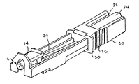
以下に、添付の図面を参照して本発明の例示的な態様を詳細に説明する。図1はカテーテル挿入装置すなわちカニューレアセンブリ10の斜視図であるが、カニューレ12は、完全に延び切った機能する位置で固定され、プッシュ−タブ14とノーズガード16は、カニューレ12をガードするための前方ガード部材18に設けられる。この前方ガード部材18は、以下に述べるように、ハウジング20(この態様では血液チャンバ34を内蔵する)からスライドするかまたは延び出る。
【0019】
図1に示すように、カテーテル挿入装置10は、カニューレ12がスライドして延び出るノーズガード16を具備する。また、このカテーテル挿入装置10には、前方ガード部材18の中に、第2のあるいは後方ガード部材24が入れ子式に設けられ、ハウジング20内に位置する。図示のように、ハウジング20は、両側に、指に係合する面26(一方のみを示す)を有する。この指に係合する面26には、穿刺のためカニューレ12あるいはこの中空針の先端を患者の体内に挿入するとき、ユーザの指が滑るのを防止し、また装置をよい握り位置で保持できるよう、リブを設けてもよい。ノーズガードは、カテーテルハブ30と対になるが、カテーテルハブ30は、ルアーロック用の突起を備え、カニューレ12の外表面にごく近い位置を延びていくカテーテルチューブを具備する。また、このカテーテルチューブは、業界でよく知られているように、可撓性で、摩擦係数が小さいテフロンなどのプラスチック材料からつくられる。
【0020】
図2の態様においては、カテーテルがカニューレ12を越えて患者の穿刺位置にまで延ばされると直ちに、カニューレはカニューレアセンブリ内の完全に保護される位置まで引き入れられる。そして、カテーテルチューブを患者の静脈に差し入れたまま、カニューレアセンブリをカテーテルハブ30から取り外すことが可能になる。このカニューレアセンブリとカテーテルハブ30の引き離しは、カテーテル挿入装置の型に応じて様々な方法で行うことができるが、これらは、例えば本出願人の米国特許出願第08/( )号(代理人整理番号9695)に開示したカテーテル挿入装置の種々の態様において記載してある。米国出願に記載したこれら方法の場合は、種々の機構が、カニューレを引き入れ保護しているカニューレアセンブリをカテーテルハブとこれに接続されたカテーテルから取り外し、分離する目的のために使用される。カテーテルハブは、ルアーロック等を備えていてもよい。この分離は、この米国出願にあるように、種々の方向に回動ないし傾斜させることができるレバー−クリップ部材を使うか、あるいは適当なプッシュ−タブとガード部材の作動を通じて行われる。
【0021】
図3および図4に見られるように、ハウジング20は、長手中空の矩形部材であり、カテーテルハブ30と長手に延びる頂壁の開口32を有する。図1および図2に見られるように、この開口32を通して血液チャンバ34を覗くことができる。図11に見られるように、血液チャンバ34は、カニューレ12の管腔と通じており、通常シリンダないし管状のスライド可能な入れ子36はその両端に、患者の体内からの大量の血液を閉鎖する封止部材38、40を具備する。
【0022】
図5〜図7に見られるように、前方ガード部材18は通常、二つの平らで平行に離隔された側壁またはアーム42、44を備える二股構造をしており、ここに設ける上方プッシュ−タブ機構46と前方タブあるいはプレート48は一体形成される。前方タブあるいはプレート48は、ノーズガード50まで延びる。この特別なノーズガード部材とカニューレの先端保護器は、種々の配置が用いられ、ノーズガードとカニューレ先端保護器のない他の設計も、他の型のカテーテル挿入装置あるいはルアーロック−カテーテル機構には適用可能である。
【0023】
後方ガード部材24は、先の前方ガード部材18と入れ子式の関係にあってスライド可能に配置され、両ガード部材間の入れ子のスライド移動を可能にするよう、二股に分れた側壁42,44がスライドして入り込む長手の通路を有する。両ガード部材18,24は、図1と2に示すように長手のハウジングに挿入することができ、ハウジングのラッチ機能は、図11(a)〜(e)ならびに図12(a)〜(e)に明瞭に示してある。
【0024】
インターロック式シーケンスあるいは入れ子式ガード部材18、24の機能については、図1を参照されたい。図11(a)と図12(a)は、カニューレ12が患者の静脈に挿入できるよう延び切って機能する状態でロックされたときの各部材の断面図である。図11(b)に見られるように、カニューレ12の手前端は、シリンダ状の入れ子36によって形成されるシリンダ状チャンバ54と通ずるよう、封止部材38を通って延び、入れ子36の反対端は、必要に応じて患者の静脈から流れてきた血液を受け止め格納するよう、もう一つの封止部材40によって封止される。
【0025】
図11(a)と図12(a)において、ハウジング20は、後方ガード部材24を完全にこの中に収め、他方、前方ガード部材18は、ほぼ完全に後方ガード部材24の中に収まっている。前方ガード部材18は、カテーテルハブ(図示せず)に入り込み、かつカニューレ12がスライドして容易に通過することができる通路58を有するノーズガード50を具備する。そして、カニューレをこの位置で包囲するよう、封止部材60を設ける。
【0026】
図11(a)と図12(a)に示した位置においては、前方ガード部材18の外径端から突出する突起62と64の対がそれぞれ、後方ガード部材24の周縁に形成された対応する凹み66に係合している。この突起の対は、後方ガード部材との間の軸方向の動きおよび回転を防止するため、後方ガード部材と互いに整列した位置にある。
【0027】
この時点において、前方ガード部材18後部の二股のアーム上には、残りのカニューレ部材とは係合していない内側に飛び出した突起70がある。
【0028】
図11(b)と12(b)に示すように、使用済みカニューレ12を患者の静脈から引き出すと同時に、カニューレアセンブリに引き込めたときは、前方ガード部材18と後方ガード部材24は、互いにロックされた位置にある。このときは、ハウジング20はグリップ面で互いに係合しているため後方に引かれ、一緒にカニューレ12と、ハウジングの遠方端にあってカニューレ12と接続しているチャンバを引き入れる。
【0029】
引き出しの第3工程においては、弾性的な二股の側壁42、44がこの位置で外側に撓むため、ハウジング20とカニューレ12をさらに動かすと同時に、前方ガード部材18にある外側に突出した突起62、64を、後方ガード部材の凹み66から外す。こうすると、同時に前方ガード部材18が後方ガード部材24から外れ、後方ガード部材24は、その後部のロック部材74、76の助けを借りて、ハウジング20にロックされる。
【0030】
第4の工程においても、ハウジング20は依然として引き込み位置にあり、二つのガード部材18,24の間で、これらガード部材が入れ子式に延び出られるよう、非ロック状態にある。
【0031】
図11(e)と図12(e)に示すように、ガード部材18,24とハウジング20が,入れ子に延び切った状態になるとすぐに、前方ガード部材18の突起62,64は露出状態になり、他方二方向ロック74,76は、ハウジング20の内側ガイドリブ80の凹み78に嵌り、同時に後方ガード部材24は、別の二方向ロック84によってハウジング20にラッチ掛けされる。ガード部材18,24とハウジング20のこれら図11(e)と図12(e)に示す位置においては、カニューレ12は、前方ガード部材18、後方ガード部材24およびハウジング20からなるカニューレアセンブリ内に完全に引き込まれている。これら前方ガード部材18、後方ガード部材24およびハウジング20は、図11(e)と図12(e)においては、入れ子式に完全に延び切った状態にあるため、すでに述べ、また前述の本出願人の米国出願にも記載してあるように、カテーテルハブをカニューレアセンブリのノーズガード端から取り外すことが可能になる。
【0032】
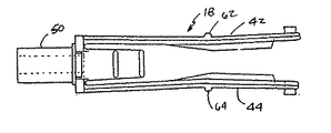
図13と14においては、今までとは異なるカテーテル挿入装置90を示す。この装置10は、患者の静脈に通したカテーテルを通じて送られている体液に流体や薬剤を追加することができるサイドポート式カテーテルであり、カテーテルハブ92は、開口可能なサイドポート94を備える。
【0033】
この態様の場合は、ルアーロック式取り外しのためにプッシュ−タブ96が設けられ、このプッシュ−タブ96は、カニューレ機構98を、ルアーロック用の突起100を備えるカテーテルハブ92から取り外すことができるように構成される。ハウジングと入れ子式の前方および後方ガード部材のその他の機構は、図1のカテーテル挿入装置の機構および機能とほぼ同じものを有する。図13に示すサイドポート式のカテーテルの態様においては、カテーテルハブ92にある突起100の形状状態を外し、全体を引き込んだカニューレアセンブリと保護状態にあるカニューレを廃棄できるよう、カテーテルハブは、ルアーロック用プッシュ−タブ96の作動によって取り外されている。
【0034】
これまでの態様は、カテーテル針の先端が医療スタッフやユーザに突き刺さる危険を及ぼすことがないよう、使用済みカニューレと中空針を保護機構に、完全に「フェイルセイフ」方式で引き込ませる機構を提供するものである。
【0035】
ハウジング20と結合した入れ子式の前方および後方ガード部材18,24は、種々の型のカテーテル挿入装置に利用でき、これらの装置は、レバー−クリップ機構や他の適当な方法によって、カテーテルハブあるいはルアーロックから取り外すことができるようになる。
【0036】
本発明に係るカニューレ保護機構の各部材は、簡単な整形部品からなっており、医療業界でよく知られ、また現在用いられている安価なプラスチックからつくることができる。
【0037】
以上本発明の好ましい態様を説明してきたが、本発明の趣旨を逸脱しない範囲で、形状や細部に種々の変更・変形を加えることは容易であろう。本発明は、ここで説明した形状その他に限定されるものではなく、特許請求の範囲に記載した範囲より狭く解釈されてはならない。
【0038】
本発明の具体的な実施態様は以下の通りである。
(A)カテーテル挿入装置のカニューレ保護機構であって、
(a)カニューレ針を収めるハウジングであって、このハウジングの端部から延びて患者にカテーテルを差し入れるのに用いられるカニューレ針を収めるハウジングと、
(b)前記ハウジングにスライド可能に取り付けられ、かつ操作位置まで延びる前記カニューレ針を通す針ガード手段を備えるカニューレ保護機構であり、
前記針ガード手段は、
(i)前記ハウジングにスライド可能に取り付けられる後方ガード部材と、
( ii )前記後方ガード部材にスライド可能に取り付けられる前方ガード部材を具備し、
前記前方ガード部材は前記後方ガード部材に引き込まれ、また前記後方ガード部材は前記カテーテル針が操作条件にある状態でハウジングに引き込まれ、
前記後方ガード部材と前方ガード部材は、前記カニューレ針が患者の身体から引き抜かれると同時にカニューレ針の保護機構を形成するよう、互いに、そしてハウジングに対して入れ子式に延び出ることができるカニューレ保護機構。
1)前記ハウジングは、一つの開口端を一つの開口側面、および中央にこのハウジング内を延びる長手のリブをもつ長手矩形の形状である上記実施態様(A)記載のカニューレ保護機構。
2)前記後方ガード部材は、前記ハウジングとの軸方向の移動のためハウジング内にスライドして挿入可能な、開口端をもつ長手矩形の形状である上記実施態様1)記載のカニューレ保護機構。
3)前記前方ガード部材は、その端部に、前記後方ガード部材と軸方向に変位できるよう、この後方ガード部材にスライドして挿入可能な、平行に延びるアームの対が連結した二股の機構が形成されている上記実施態様2)記載のカニューレ保護機構。
4)前記前方ガード部材の外表面にある突起は、前記ハウジング内で前方および後方ガード部材が引き込み位置にあるとき、後方ガード部材の凹みとラッチ係合する上記実施態様3)記載のカニューレ保護機構。
5)前記両ガード部材は、第1段階の一部延び出た位置においては、これらガード部材間の軸方向の動きを防止するよう前記突起が前記凹みとラッチ係合した状態で、前記ハウジングから一部延び出す上記実施態様4)記載のカニューレ保護機構。
6)前記両ガード部材の第2段階のさらに一部延び出た位置においては、前記突起が前記凹みから外れており、前方ガード部材は後方ガード部材から一部延び出ている上記実施態様5)記載のカニューレ保護機構。
7)前記両ガード部材の第3段階のさらに一部延び出た位置においては、前記後方ガード部材と前記ハウジングをこの延び出した位置で互いにロック状態に置くため、後方ガード部材のロック手段が、前記ハウジングの長手リブにある凹みとラッチ係合している上記実施態様6)記載のカニューレ保護機構。
8)前記両ガード部材が完全に延び切った位置においては、前記前方ガード部材は前記後方ガード部材からさらに延び出しており、これら両ガード部材をこの完全に延び切った状態に維持するよう、これらガード部材にはラッチ手段が係合して、前記カニューレ針はこれら両ガード部材の中に完全に引き込まれている上記実施態様7)記載のカニューレ保護機構。
9)前記ロック手段は、前記両ガード部材の第1段階の一部延び出た状態においては、前記凹部から外れている上記実施態様7)記載のカニューレ保護機構。
10)前記突起と凹み間のラッチ掛けと前記ロック手段とラッチ手段のラッチ掛けの際にはそれぞれ、前記両ガード部材の連続的な延び出しにおける特定の状態を示す音が発生する上記実施態様8)記載のカニューレ保護機構。
11)前記前方ガード部材は、カテーテルのカテーテルハブとの連結用のノーズガードを具備する上記実施態様3)記載のカニューレ保護機構。
12)前記ハウジング、前方ガード部材および後方ガード部材はそれぞれ、プラスチック材料から形成される上記実施態様(A)記載のカニューレ保護機構。
【0039】
【発明の効果】
以上説明したように、本発明によれば、使用済みの静脈カテーテル針先端の保護器と安全機構が提供される。
【図面の簡単な説明】
【図1】本発明の第1の態様に係るカテーテル挿入装置の斜視図(カニューレは完全に延ばした操作位置にある)。
【図2】図1に似た、本発明の第1の態様に係るカテーテル挿入装置の斜視図(カニューレは完全に引き込められ、保護された位置にある)。
【図3】カニューレアセンブリのハウジング部材の側面図。
【図4】図3のハウジング部材の正面図。
【図5】カニューレの前方ガード部材の頂面図。
【図6】カニューレの前方ガード部材の側面図。
【図7】カニューレの前方ガード部材の正面図。
【図8】ハウジング部材およびカニューレアセンブリ機構の前方ガード部材と入れ子式に連結した後方ガード部材の頂面図。
【図9】ハウジング部材およびカニューレアセンブリ機構の前方ガード部材と入れ子式に連結した後方ガード部材の側面図。
【図10】ハウジング部材およびカニューレアセンブリ機構の前方ガード部材と入れ子式に連結した後方ガード部材の正面図。
【図11】図11(a)〜図11(e)は、図3ないし図10に示したインターロック式シーケンス入れ子状ガード部材の種々の操作位置を表す図4の11−11線断面図。
【図12】図12(a)〜図12(e)は、図11(a)〜図11(e)に似た、図4の12−12線断面図。
【図13】本発明の他の態様に係るサイドポート方式のカテーテル挿入装置の斜視図(カニューレは完全に延ばした操作位置にある)。
【図14】図13のカテーテル挿入装置(カニューレは完全に引き込められた位置にあり、カテーテルのサイドポート部はカニューレから分離してある)の拡散分解図。[0001]
BACKGROUND OF THE INVENTION
The present invention relates generally to a venous catheter insertion device, and more particularly to a catheter needle tip protector and a catheter needle tip protector that automatically operates simultaneously with the withdrawal of a cannula from a patient's puncture position and used by a medical staff. The present invention relates to a safety mechanism that provides fail-safe protection without accidental puncture of a catheter needle.
[0002]
In particular, according to certain aspects of the present invention, a catheter insertion device is provided that includes an interlocking sequence guard member that can be used with a wide variety of catheter insertion devices. Important in this aspect is that the used cannula is fully retracted into the protective mechanism (ie, the housing) prior to removal from the catheter hub, providing a fail-safe safety protection mechanism. Previously, the tip of the used cannula needle has slightly protruded from the protective device, creating a risk to the surgeon and medical staff who are users of the catheter insertion device when pulling the cannula assembly away from the catheter and the catheter hub attached to it. There was a thing. Various designs of catheter insertion devices in use today, including so-called Luer lock and side port catheters, bring the retracted used cannula and its housing and protection mechanism into the patient's venipuncture position. Various mechanisms are used to separate the catheter and catheter hub as they are inserted. As is well known in the medical industry, a catheter is connected to various sources such as blood, body fluids other than blood, and drugs when injecting fluid into a vein.
[0003]
An important advantage of the present invention is that the housing for retracting the used cannula or hollow needle or the telescoping sequence guard can be used to remove the housing containing the used cannula from the catheter hub when the catheter and cannula are pulled apart. In addition, not only visually but also audibly clearly informing that the cannula has been retracted.
[0004]
In accordance with a particular aspect of the present invention applicable to the various types of catheter insertion devices described below, a mechanism is provided that includes an interlocking sequence guard member. According to this mechanism, when the guard members are telescopically retracted together to finally form a multiple locking system that continuously generates clicking sounds, a plurality of nesting steps result in a cannula including a hollow needle. It is pulled into the guard member. This mechanism allows medical staff operating the catheter insertion device to know that the cannula has been fully retracted and locked in place and protected. This eliminates danger to the user of the device and allows the needle or cannula housing mechanism to be safely pulled away from the catheter hub.
[0005]
[Prior art]
Medical devices that pierce a patient's skin using a hollow needle or cannula with a sharp tip are well known in the industry and are widely used by surgeons and medical staff to inject fluids and drugs directly into the patient's bloodstream. It is used. In addition, transfusions and administration of fluids other than blood often have to be performed on patients during surgery. In order to inject such body fluids into the cardiovascular system, the needle is basically connected to the source of the fluid to be injected into the vein on the front side, as is well known and has been done for a long time. The vein must be punctured using a hollow rigid needle with a part.
[0006]
However, there have been some significant medical technical problems with the method of piercing the patient's veins for administration. The biggest problem is usually due to the stiffness of the needle using surgical grade steel, and while the needle is inserted into a patient's vein for blood transfusion or fluid administration, the needle is safe. Therefore, it is necessary to maintain a solid posture in a normal place where puncturing is performed, but such an operation requires a considerable amount of time. In addition, it may be necessary to collect blood samples from time to time or continuously administer bodily fluids to the patient's veins, in which case the patient must be punctured many times. Since this puncture is performed at a different part of the body for a predetermined time, such repeated venipuncture with pain and discomfort is an experience similar to trauma for the patient.
[0007]
In order to improve, if possible, the above-mentioned medical technical problems, recently, a method has been adopted in which a flexible catheter tube made of a low friction material such as silane or Teflon is inserted into a patient's vein. In addition, the catheter tube is allowed to stay in the vein for a longer time than before, for example, for regular administration of fluids containing body fluids, blood / plasma transfusion, liquid drug administration, blood sample collection, etc. Yes. In this way, trauma, blood spillage, infiltration, etc. that could not be avoided by repeated venipunctures were almost eliminated, leaving the rigid needle in the body for a long time and giving the patient danger and discomfort. Therefore, in order to locate the distal end of such a flexible catheter in the patient's body cavity (vascular gap or vein), it is now common to use a cannula or a hollow needle with a sharp tip for puncture. is there. After the puncture, a flexible catheter tube that can be telescopically attached to the outer wall of the cannula or hollow needle, that is slidably and coaxially attached, can be extended around the needle. Proceed to the vein. Thereafter, with the catheter tube remaining in the patient's body at the puncture position, the needle is withdrawn from the inside of the catheter tube, and the needle is discarded by an appropriate method.
[0008]
The needle placed in the patient's body immediately after the puncture may be used if the patient is currently infected with nearly lethal AIDS (AIDS) or under other dangerous infectious conditions such as hepatitis Medical staff may inadvertently puncture themselves with a used needle that has been removed from the patient's body due to carelessness or accident, resulting in the same disease and death There is danger.
[0009]
Previously, when removing a device to house a used withdrawal needle or cannula from the locking mechanism on the catheter hub (the catheter hub is attached to a flexible catheter tube entering the patient's puncture location) The surgeon had to separate the catheter hub and the used cannula with both hands. The separation of the catheter hub and the used cannula can then be achieved by attaching a Luer lock to the catheter hub so that fluid can be introduced into the vein, blood / plasma can be delivered, or other drugs can be administered. This is because it can be attached to the locking protrusion. However, for this purpose, medical staff often have to perform two or three operations almost simultaneously or in a hurry, so it was difficult to operate and had to use both hands. And in practice, one of these sequential operations was delayed, sometimes leaving the operation of separating the catheter and cannula unfinished.
[0010]
Although telescoping members that protect the used cannula of the catheter insertion device are now known in the industry, these telescoping members are interlock sequence telescoping guard members that retract and protect the cannula "fail-safe" Is not intended to be used.
[0011]
U.S. Pat. No. 4,950,252 (Luther et al.) Discloses a cannula guard housing mechanism that extends axially relative to each other to contain and protect used cannulas.
[0012]
U.S. Pat. No. 4,944,725 (McDonald) discloses a venous catheter that protects the surgeon from accidental punctures and eliminates the risk of dangerous infection from the patient. The catheter is introduced into the patient's body with the help of a hollow needle or cannula mechanism, and then withdrawn from the patient's body into a protective housing, but the needle is not exposed at any time during this withdrawal. Absent. The housing is latched in place so that the catheter hub is unlocked in place after a certain time has elapsed after the needle has been retracted and can be retracted and locked in a series of operations.
[0013]
There are other references on how to protect the tip of the needle after it has been withdrawn from the patient's body or at the same time. U.S. Pat. No. 4,790,828 (Dombrowski et al.) Discloses a foldable yoke that surrounds a needle to ensure that the needle is retracted into a sheath-extending mechanism to ensure that the used needle does not pierce the medical staff. A nose portion or nose cap that is connected to the housing by a mechanism is disclosed.
[0014]
[Problems to be solved by the invention]
Accordingly, it is an object of the present invention to provide a catheter insertion device that allows a used cannula to be “fail-safe” drawn into a telescoping sequence guard mechanism.
[0015]
A more focused object of the present invention is a guard mechanism that retracts a used cannula before removal from the catheter, and a safe and complete retraction of the cannula protection mechanism through a plurality of removably locked sequence guard members. It is to provide a guard mechanism that guarantees.
[0016]
Another one of the present inventionthe purposeIs to provide a catheter insertion device with an interlocking sequence guard member that fully retracts a used cannula through a sequenced engagement and disengagement of a plurality of axially spaced locking devices. Each locking device audibly informs the user that the cannula has been fully retracted and increases the certainty of the locking action.
[0017]
[Means for Solving the Problems]
Therefore, the present invention provides two sleeve-shaped guard members that are nested and moved in sequence in order to provide a mechanism for protecting a used cannula, in particular, a safe mechanism that functions as “fail-safe”. In this way, the locking device allows the cannula to be extended in a locked state before it can be used to guide the catheter into the patient's vein. Thereafter, when the cannula is retracted, a first stretching step is performed in which each member is locked and the outer sleeve passes over a recess in one of the guard members. Thereafter, in the second stage, the inner guard members are in an unlocked state, and the sleeve can be further extended rearward with the second two-way lock in the unlocked position. In the further extended stage, the initial locking mechanism is unlocked, and the second locking mechanism is also unlocked. Placed in. At this time, the front guard member is locked to the rear guard member and the rear guard member is locked to the sleeve-shaped housing so as to completely enclose the cannula.
[0018]
DETAILED DESCRIPTION OF THE INVENTION
In the following, exemplary embodiments of the present invention will be described in detail with reference to the accompanying drawings. FIG. 1 shows a catheter insertion deviceIe cannula assembly10 is a perspective view,Cannula12 fully extendedFunctionFixed in position, the push-
[0019]
As shown in FIG. 1, the catheter insertion device 10 includes a
[0020]
In the embodiment of FIG. 2, as soon as the catheter is extended beyond the
[0021]
As seen in FIGS. 3 and
[0022]
As can be seen in FIGS.The
[0023]
The
[0024]
See FIG. 1 for the function of the interlocking sequence or
[0025]
11 (a) and 12 (a), the
[0026]
11 (a) and 12 (a), a pair of
[0027]
At this point, on the bifurcated arm at the rear of the
[0028]
As shown in FIGS. 11 (b) and 12 (b), when the used
[0029]
PullIn the third step, the elastic
[0030]
Also in the fourth step, the
[0031]
As shown in FIGS. 11 (e) and 12 (e), as soon as the
[0032]
13 and 14, a different
[0033]
In this embodiment, a push-
[0034]
Previous aspects provide a mechanism that allows the used cannula and hollow needle to be retracted into the protective mechanism in a completely “fail-safe” manner so that the tip of the catheter needle does not pose a risk of sticking to medical staff or users. Is.
[0035]
The telescoping front and
[0036]
Each member of the cannula protection mechanism according to the present invention consists of simple shaping parts and can be made from inexpensive plastics well known in the medical industry and currently used.
[0037]
Although the preferred embodiments of the present invention have been described above, it will be easy to add various changes and modifications to the shape and details without departing from the spirit of the present invention. The present invention is not limited to the shapes and the like described herein, and should not be construed as narrower than the scope described in the claims.
[0038]
Specific embodiments of the present invention are as follows.
(A) A cannula protection mechanism of a catheter insertion device,
(A) a housing that houses a cannula needle that houses a cannula needle that extends from an end of the housing and is used to insert a catheter into a patient;
(B) a cannula protection mechanism comprising needle guard means for passing the cannula needle slidably attached to the housing and extending to an operating position;
The needle guard means includes
(I) a rear guard member slidably attached to the housing;
( ii ) Comprising a front guard member slidably attached to the rear guard member;
The anterior guard member is retracted into the posterior guard member, and the posterior guard member is retracted into the housing with the catheter needle in operating condition;
The posterior guard member and the anterior guard member can extend out of each other and the housing telescopically to form a cannula needle protection mechanism as the cannula needle is withdrawn from the patient's body. .
1) The housing has a rectangular shape with one open end, one open side, and a central long rib extending in the housing.Embodiment (A) aboveThe described cannula protection mechanism.
2) The cannula protection mechanism according to the above embodiment 1), wherein the rear guard member has an elongated rectangular shape with an open end that can be slid into the housing for axial movement with respect to the housing.
3) The front guard member has a bifurcated mechanism connected to a pair of arms extending in parallel and slidable into the rear guard member so that the front guard member can be displaced axially with the rear guard member. The cannula protection mechanism according to the above embodiment 2), which is formed.
4) The cannula protection mechanism according to the above embodiment 3), wherein the projection on the outer surface of the front guard member latches with the recess of the rear guard member when the front and rear guard members are in the retracted position in the housing. .
5) In a position where the both guard members partially extend in the first stage, the protrusions are latched with the recesses to prevent axial movement between the guard members, and the guard members are separated from the housing. The cannula protection mechanism according to embodiment 4), which partially extends.
6) In the above-described embodiment 5 in which the protrusion is removed from the recess at the position where the second stage of the two guard members further extends, and the front guard member partially extends from the rear guard member. The described cannula protection mechanism.
7) In order to place the rear guard member and the housing in a locked state at the extended position in a part of the third stage of the guard members, the locking means of the rear guard member includes: A cannula protection mechanism according to embodiment 6) in latching engagement with a recess in the longitudinal rib of the housing.
8) In the position where both guard members are fully extended, the front guard member extends further from the rear guard member, and these guard members are maintained in the fully extended state. A cannula protection mechanism according to embodiment 7), wherein latch means are engaged with the guard member, and the cannula needle is fully retracted into both guard members.
9) The cannula protection mechanism according to the embodiment 7), wherein the locking means is disengaged from the concave portion in a state in which the first guard member is partially extended in the first stage.
10) The above embodiment 8 in which a sound indicating a specific state in the continuous extension of the both guard members is generated at the time of latching between the protrusion and the recess and the latching of the locking means and the latching means, respectively. ) Cannula protection mechanism as described.
11) The cannula protection mechanism according to the above embodiment 3), wherein the front guard member includes a nose guard for connection with a catheter hub of a catheter.
12) The housing, the front guard member and the rear guard member are each formed from a plastic material.Embodiment (A) aboveThe described cannula protection mechanism.
[0039]
【The invention's effect】
As described above, according to the present invention, a used venous catheter needle tip protector and a safety mechanism are provided.
[Brief description of the drawings]
FIG. 1 is a perspective view of a catheter insertion device according to a first aspect of the present invention (cannula in fully extended operating position).
2 is a perspective view of the catheter insertion device according to the first aspect of the present invention, similar to FIG. 1 (cannula fully retracted and in a protected position). FIG.
FIG. 3 is a side view of a housing member of a cannula assembly.
4 is a front view of the housing member of FIG. 3;
FIG. 5 is a top view of the anterior guard member of the cannula.
FIG. 6 is a side view of the anterior guard member of the cannula.
FIG. 7 is a front view of the anterior guard member of the cannula.
FIG. 8 is a top view of a rear guard member telescopically coupled with a front guard member of the housing member and cannula assembly mechanism.
FIG. 9 is a side view of a rear guard member telescopically coupled with a front guard member of the housing member and cannula assembly mechanism.
FIG. 10 is a front view of the rear guard member telescopingly connected with the front guard member of the housing member and cannula assembly mechanism.
11 (a) to 11 (e) are cross-sectional views taken along line 11-11 of FIG. 4 showing various operation positions of the interlock type sequence nested guard member shown in FIGS. 3 to 10. FIG.
12 (a) to 12 (e) are cross-sectional views taken along line 12-12 of FIG. 4, similar to FIGS. 11 (a) to 11 (e).
13 is a perspective view of a side port type catheter insertion device according to another aspect of the present invention (cannula in fully extended operating position). FIG.
14 is a diffusion exploded view of the catheter insertion device of FIG. 13 (where the cannula is in a fully retracted position and the side port portion of the catheter is separated from the cannula).
Claims (12)
(a)カニューレと、
(b)前記カニューレを受け入れるハウジングであって、前記カニューレは前記ハウジングの端部から延びて患者にカテーテルを差し入れるように構成されている、ハウジングと、
(c)前記ハウジング内にスライド可能に取り付けられたカニューレガード手段であって、当該カニューレの機能状態においては前記カニューレが当該カニューレガード手段の内部を通って延びる、カニューレガード手段を備え、
前記カニューレガード手段は、
(i)前記ハウジングにスライド可能に取り付けられた後方ガード部材と、
(ii)前記後方ガード部材にスライド可能に取り付けられた前方ガード部材を具備し、
前記カニューレが機能する状態では、前記前方ガード部材が前記後方ガード部材に引き込まれているとともに前記後方ガード部材が前記ハウジングに引き込まれていて、
前記後方ガード部材と前方ガード部材は、前記カニューレが患者の身体から引き抜かれると同時に前記カニューレを収容して保護するように、前記ハウジングに対して互いに入れ子式に延び出ることができ、
前記カニューレは、前記ハウジングの一部の長さにわたってのみ延在する、
カニューレ保護機構。 In cannula protection mechanism for protecting a cannula of a catheter insertion device,
(A) a cannula;
(B) a housing for receiving the cannula, the cannula is configured to insert a catheter into the patient extending from an end portion of the housings, and housings,
A cannula guard section slidably mounted in (c) said housing, said cannula in the functional state of the cannula extends through the interior of the cannula guard means comprises a Kanyurega over de means,
Before Symbol Kanyurega over de means,
(I) a rear guard member slidably attached to the housing;
(Ii) comprising a front guard member slidably attached to the rear guard member;
In a state in which the cannula is to function, the rear guard member is not drawn into the housings together with the front guard member is drawn into the rear guard member,
The rear guard member and the front guard member, as the Kanyu Les protect houses the Kanyu Les simultaneously withdrawn from the patient's body, can extend out telescopically with one another with respect to the housing,
The cannula extends only over the length of a portion of the housing;
Cannula protection mechanism.
前記ハウジングは、一つの開口端および一つの開口側面を有する長手矩形の構造と、当該ハウジング内に延びる中央の長手リブとを有している、カニューレ保護機構。 The cannula protection mechanism, wherein the housing has a longitudinal rectangular structure having one open end and one open side, and a central longitudinal rib extending into the housing.
前記後方ガード部材は、前記ハウジングに対して軸方向に移動するようにハウジング内にスライド可能に挿入される、開口端をもつ長手矩形の構造を有している、カニューレ保護機構。 The cannula protection mechanism, wherein the rear guard member has a longitudinal rectangular structure with an open end that is slidably inserted into the housing for axial movement relative to the housing.
前記前方ガード部材は、その端部に連結されて二股の構造を形成するように平行に延びるアームの対を有し、前記アームは、前記後方ガード部材に対して軸方向に変位できるように前記後方ガード部材にスライド可能に挿入される、カニューレ保護機構。 The front guard member has a pair of arms extending in parallel so as to be connected to an end thereof to form a bifurcated structure, and the arm can be displaced in an axial direction with respect to the rear guard member. A cannula protection mechanism slidably inserted into the posterior guard member.
前記前方ガード部材の外面に突起を設けてあるとともに前記後方ガード部材に凹みを設けてあり、前記両ガード部材が前記ハウジング内に引き込まれた位置にあるとき、前記突起は前記凹みとラッチ係合している、カニューレ保護機構。 A protrusion is provided on the outer surface of the front guard member, and a recess is provided in the rear guard member. When the two guard members are in a position retracted into the housing, the protrusion is latched with the recess. The cannula protection mechanism.
前記両ガード部材が部分的に延び出た第1の状態において、前記両ガード部材は前記ハウジングから一部延び出すが、前記突起は前記凹みとラッチ係合した状態に留まって前記両ガード部材の間の相対的な軸方向の動きを防止している、カニューレ保護機構。 In the first state in which the two guard members partially extend, the two guard members partially extend from the housing, but the protrusion remains in latch engagement with the recess. Cannula protection mechanism, preventing relative axial movement between.
前記両ガード部材が部分的に更に延び出た第2の状態において、前記突起は前記凹みから外れ、前記前方ガード部材は前記後方ガード部材から部分的に延び出ている、カニューレ保護機構。 The cannula protection mechanism, wherein in the second state where both the guard members partially extend further, the protrusion is removed from the recess, and the front guard member partially extends from the rear guard member.
前記両ガード部材が部分的に更に延び出た第3の状態において、前記ハウジングと前記後方ガード部材を相互に延び出た位置にロックするため、前記後方ガード部材のロック手段が、前記ハウジングの前記長手のリブにある凹みとラッチ係合している、カニューレ保護機構。 In the third state in which both the guard members partially extend further, the locking means of the rear guard member is used to lock the housing and the rear guard member in a mutually extended position. A cannula protection mechanism in latching engagement with a recess in the longitudinal rib.
前記両ガード部材が完全に延び出た状態において、前記前方ガード部材は前記後方ガード部材に関して更に延び出ており、前記両ガード部材をこの完全に延び切った状態に維持するように前記両ガード部材にラッチ手段が係合し、これによって前記カニューレは前記両ガード部材の中に完全に引き込まれている、カニューレ保護機構。 In a state where the two guard members are fully extended, the front guard member extends further with respect to the rear guard member, and the two guard members are maintained so as to keep the two guard members fully extended. A cannula protection mechanism, wherein the latch means is engaged, whereby the cannula is fully retracted into the two guard members.
前記ロック手段は、前記両ガード部材が引き込まれた状態および部分的に延び出た第1の状態において、前記凹部から外れている、カニューレ保護機構。 The locking means is a cannula protection mechanism in which both the guard members are disengaged from the recess in the retracted state and the partially extended first state.
前記突起と凹みの間のラッチ動作、および前記ロック手段とラッチ手段のラッチ動作はそれぞれ、前記両ガード部材の連続的な延び出しにおける具体的な状態を示す所定の可聴音を発生する、カニューレ保護機構。 The latching action between the protrusion and the recess and the latching action of the locking means and the latching means each generate a predetermined audible sound indicating a specific state in the continuous extension of the two guard members. mechanism.
前記前方ガード部材は、カテーテルのカテーテルハブと連結するノーズガードを具備している、カニューレ保護機構。 The anterior guard member includes a nose guard that connects with a catheter hub of a catheter.
Applications Claiming Priority (2)
| Application Number | Priority Date | Filing Date | Title |
|---|---|---|---|
| US08/483,950 US5562631A (en) | 1995-06-07 | 1995-06-07 | Catheter arrangement with interlocking sequenced guarding members for protecting cannula |
| US483950 | 1995-06-07 |
Publications (2)
| Publication Number | Publication Date |
|---|---|
| JPH0999070A JPH0999070A (en) | 1997-04-15 |
| JP3805431B2 true JP3805431B2 (en) | 2006-08-02 |
Family
ID=23922150
Family Applications (1)
| Application Number | Title | Priority Date | Filing Date |
|---|---|---|---|
| JP16517796A Expired - Lifetime JP3805431B2 (en) | 1995-06-07 | 1996-06-06 | Catheter mechanism with interlocking sequence guard member for cannula protection |
Country Status (19)
| Country | Link |
|---|---|
| US (1) | US5562631A (en) |
| EP (1) | EP0747084B1 (en) |
| JP (1) | JP3805431B2 (en) |
| KR (1) | KR100424964B1 (en) |
| CN (1) | CN1119184C (en) |
| AR (1) | AR002375A1 (en) |
| AU (1) | AU5463396A (en) |
| BR (1) | BR9602674A (en) |
| CA (1) | CA2178249C (en) |
| CO (1) | CO4520195A1 (en) |
| DE (1) | DE69612425T2 (en) |
| ES (1) | ES2155577T3 (en) |
| IL (1) | IL118318A (en) |
| NO (1) | NO311787B1 (en) |
| NZ (1) | NZ286626A (en) |
| RU (1) | RU2169585C2 (en) |
| SG (1) | SG47144A1 (en) |
| TW (1) | TW347340B (en) |
| ZA (1) | ZA964783B (en) |
Families Citing this family (113)
| Publication number | Priority date | Publication date | Assignee | Title |
|---|---|---|---|---|
| US5688249A (en) * | 1995-03-28 | 1997-11-18 | Johnson & Johnson Medical, Inc. | Telescoping members for catheter introducer assembly |
| US5562631A (en) * | 1995-06-07 | 1996-10-08 | Johnson & Johnson Medical, Inc. | Catheter arrangement with interlocking sequenced guarding members for protecting cannula |
| US5879337A (en) * | 1997-02-27 | 1999-03-09 | Injectimed, Inc. | Needle tip guard for hypodermic needles |
| BR9707764A (en) | 1996-02-27 | 2000-01-04 | Injectimed Inc | Needle tip protector for hypodermic needles. |
| US5651772A (en) | 1996-02-28 | 1997-07-29 | Aeroquip Corporation | Needle guard assembly |
| US5921969A (en) * | 1996-04-22 | 1999-07-13 | Vallelunga; Anthony J. | Apparatus for shielding a butterfly needle |
| US5683368A (en) | 1996-09-19 | 1997-11-04 | Johnson & Johnson Medical, Inc. | Controlled motion lock for safety catheter |
| US5954698A (en) | 1997-01-08 | 1999-09-21 | Vadus, Inc. | Catheter apparatus having valved catheter hub and needle protector |
| US6080137A (en) | 1997-01-08 | 2000-06-27 | Vadus, Inc. | Needle protector |
| US6607509B2 (en) * | 1997-12-31 | 2003-08-19 | Medtronic Minimed, Inc. | Insertion device for an insertion set and method of using the same |
| US7329239B2 (en) * | 1997-02-05 | 2008-02-12 | Medtronic Minimed, Inc. | Insertion device for an insertion set and method of using the same |
| US6749588B1 (en) * | 1998-04-09 | 2004-06-15 | Becton Dickinson And Company | Catheter and introducer needle assembly with needle shield |
| US6117110A (en) * | 1999-03-26 | 2000-09-12 | Radmand; Reza | Catheter needle safety device and method of using same |
| US20050192481A1 (en) * | 1999-10-14 | 2005-09-01 | George Berci | Laryngoscope and camera coupling |
| GB2355933B (en) * | 1999-11-03 | 2003-08-13 | Nmt Group Plc | Catheter Device |
| US8226617B2 (en) | 1999-11-04 | 2012-07-24 | Tyco Healthcare Group Lp | Safety shield apparatus and mounting structure for use with medical needle devices |
| US6280420B1 (en) | 1999-11-04 | 2001-08-28 | Specialized Health Products | Reaccessible medical needle safety devices and methods |
| US7029461B2 (en) | 1999-11-04 | 2006-04-18 | Tyco Healthcare Group Lp | Safety shield for medical needles |
| US6592556B1 (en) | 2000-07-19 | 2003-07-15 | Tyco Healthcare Group Lp | Medical needle safety apparatus and methods |
| US7052483B2 (en) * | 2000-12-19 | 2006-05-30 | Animas Corporation | Transcutaneous inserter for low-profile infusion sets |
| US7001363B2 (en) | 2002-04-05 | 2006-02-21 | F. Mark Ferguson | Safety shield for medical needles |
| JP3808806B2 (en) * | 2002-06-26 | 2006-08-16 | メディキット株式会社 | Indwelling needle |
| DE20210394U1 (en) | 2002-07-04 | 2002-09-12 | Braun Melsungen Ag | catheter introducer |
| WO2004045701A1 (en) * | 2002-11-19 | 2004-06-03 | Peter Balfour Dugmore | Safety intravascular catheter |
| DE10333118B4 (en) * | 2002-11-29 | 2008-02-21 | Disetronic Licensing Ag | Puncture device for piercing a hypodermic needle |
| US7125396B2 (en) * | 2002-12-30 | 2006-10-24 | Cardinal Health 303, Inc. | Safety catheter system and method |
| WO2005009525A1 (en) | 2003-07-21 | 2005-02-03 | Disetronic Licensing Ag | Insertion device for inserting an injection needle |
| IL157981A (en) | 2003-09-17 | 2014-01-30 | Elcam Medical Agricultural Cooperative Ass Ltd | Auto-injector |
| US7494481B2 (en) * | 2004-12-03 | 2009-02-24 | Medtronic Minimed, Inc. | Multi-position infusion set device and process |
| US7520867B2 (en) * | 2003-11-10 | 2009-04-21 | Medtronic Minimed, Inc. | Subcutaneous infusion set |
| IL160891A0 (en) | 2004-03-16 | 2004-08-31 | Auto-mix needle | |
| US9162037B2 (en) | 2005-07-06 | 2015-10-20 | Vascular Pathways, Inc. | Intravenous catheter insertion device and method of use |
| US20070060890A1 (en) * | 2005-09-08 | 2007-03-15 | Cuppy Medical Products, Inc. | Catheter safety tube needle retraction system |
| US7670317B2 (en) * | 2005-10-25 | 2010-03-02 | Becton, Dickinson And Company | One piece low drag septum |
| US7798994B2 (en) * | 2005-11-15 | 2010-09-21 | Becton, Dickinson And Company | Needle shield to septum interconnect |
| US20070191777A1 (en) * | 2006-02-16 | 2007-08-16 | Medex, Inc. | Enclosed Needle Device with Fluid Path Access |
| US8496627B2 (en) | 2006-03-21 | 2013-07-30 | Covidien Lp | Passive latch ring safety shield for injection devices |
| US8235945B2 (en) * | 2006-06-08 | 2012-08-07 | Rishi Baid | Safety device to cover the needle tip of intravenous catheter apparatus |
| US8308691B2 (en) | 2006-11-03 | 2012-11-13 | B. Braun Melsungen Ag | Catheter assembly and components thereof |
| EP2108394B1 (en) | 2006-08-28 | 2017-12-06 | Poly Medicure Ltd. | Protector cover assembly |
| WO2008115102A1 (en) * | 2007-03-16 | 2008-09-25 | Carmel Pharma Ab | A piercing member protection device |
| GB2448885A (en) * | 2007-05-01 | 2008-11-05 | Iden Shams | Needle-piercing assembly |
| EP2272432B1 (en) | 2007-05-07 | 2012-03-14 | Vascular Pathways Inc. | Intravenous catheter insertion and blood sample devices |
| WO2009034579A1 (en) * | 2007-09-06 | 2009-03-19 | Manoj Kumar Maan | Safety i. v. cannula |
| US9295786B2 (en) * | 2008-05-28 | 2016-03-29 | Medtronic Minimed, Inc. | Needle protective device for subcutaneous sensors |
| US20110201887A1 (en) * | 2008-10-17 | 2011-08-18 | Koninklijke Philips Electronics N.V. | Interlocking nested cannula |
| US9149581B2 (en) * | 2009-03-09 | 2015-10-06 | Glucago Llc | Compact device for rapidly mixing and delivering substances to a patient |
| WO2011011436A2 (en) | 2009-07-21 | 2011-01-27 | The General Hospital Corporation D/B/A | Peripheral blood sampling methods and devices |
| US8323249B2 (en) | 2009-08-14 | 2012-12-04 | The Regents Of The University Of Michigan | Integrated vascular delivery system |
| US9950139B2 (en) | 2010-05-14 | 2018-04-24 | C. R. Bard, Inc. | Catheter placement device including guidewire and catheter control elements |
| US8932258B2 (en) | 2010-05-14 | 2015-01-13 | C. R. Bard, Inc. | Catheter placement device and method |
| US11925779B2 (en) | 2010-05-14 | 2024-03-12 | C. R. Bard, Inc. | Catheter insertion device including top-mounted advancement components |
| US9872971B2 (en) | 2010-05-14 | 2018-01-23 | C. R. Bard, Inc. | Guidewire extension system for a catheter placement device |
| US10384039B2 (en) | 2010-05-14 | 2019-08-20 | C. R. Bard, Inc. | Catheter insertion device including top-mounted advancement components |
| US8771230B2 (en) | 2010-05-19 | 2014-07-08 | Tangent Medical Technologies, Llc | Integrated vascular delivery system |
| WO2011146772A1 (en) | 2010-05-19 | 2011-11-24 | Tangent Medical Technologies Llc | Safety needle system operable with a medical device |
| EP2600925B9 (en) | 2010-08-05 | 2021-11-10 | B. Braun Melsungen AG | Needle safety device and assembly |
| US8690833B2 (en) | 2011-01-31 | 2014-04-08 | Vascular Pathways, Inc. | Intravenous catheter and insertion device with reduced blood spatter |
| ES2750035T3 (en) | 2011-02-25 | 2020-03-24 | Bard Inc C R | Medical component insertion device including a retractable needle |
| US9238104B2 (en) | 2011-02-28 | 2016-01-19 | Injectimed, Inc. | Needle guard |
| US8764711B2 (en) | 2011-02-28 | 2014-07-01 | Injectimed, Inc. | Needle guard |
| EP2510964A1 (en) * | 2011-04-11 | 2012-10-17 | Becton Dickinson France | Needle assembly and injection device with foldable needle protecting means |
| US20120277757A1 (en) * | 2011-04-13 | 2012-11-01 | Curax, Llc | Multi-function cannulated surgical device |
| US10076272B2 (en) | 2011-04-26 | 2018-09-18 | Velano Vascular, Inc. | Systems and methods for phlebotomy through a peripheral IV catheter |
| US9186100B2 (en) | 2011-04-26 | 2015-11-17 | Velano Vascular, Inc. | Systems and methods for phlebotomy through a peripheral IV catheter |
| US8366685B2 (en) | 2011-04-26 | 2013-02-05 | Creative Vascular, Llc | Systems and methods for phlebotomy through a peripheral IV catheter |
| USD903101S1 (en) | 2011-05-13 | 2020-11-24 | C. R. Bard, Inc. | Catheter |
| CN204337490U (en) | 2011-12-07 | 2015-05-20 | 贝克顿·迪金森公司 | Infusion device system, two-piece type fluid connector and molectron |
| US9889255B2 (en) | 2011-12-07 | 2018-02-13 | Becton, Dickinson And Company | Needle shielding assemblies and infusion devices for use therewith |
| EA201491258A1 (en) * | 2011-12-21 | 2015-01-30 | Уолкил Консептс, Инк. | Self-flashing catheters |
| US8414539B1 (en) | 2011-12-27 | 2013-04-09 | B. Braun Melsungen Ag | Needle tip guard for percutaneous entry needles |
| US20140058319A1 (en) * | 2012-03-20 | 2014-02-27 | Glucago Llc | Compact Device For Rapidly Mixing and Delivering Substances To a Patient |
| AU2012379922B2 (en) * | 2012-05-16 | 2017-07-20 | Mitsubishi Pencil Company, Limited | Catheter assembly |
| US8992469B2 (en) | 2012-06-26 | 2015-03-31 | Glucago Llc | Reconstitution device |
| US9125995B2 (en) | 2012-12-05 | 2015-09-08 | Glucago Llc | Reconstitution devices |
| USD747456S1 (en) | 2012-12-07 | 2016-01-12 | Becton, Dickinson And Company | Infusion set assembly |
| USD747458S1 (en) | 2012-12-07 | 2016-01-12 | Becton, Dickinson And Company | Infusion set insertion needle assembly |
| USD747459S1 (en) | 2012-12-07 | 2016-01-12 | Becton, Dickinson And Company | Infusion set assembly |
| CN105102054B (en) | 2013-01-30 | 2018-04-20 | 血管通路股份有限公司 | The system and method placed for venipuncture and conduit |
| CA2937744C (en) | 2014-02-04 | 2022-08-09 | Icu Medical, Inc. | Self-priming systems and methods |
| WO2016037127A1 (en) | 2014-09-05 | 2016-03-10 | C.R. Bard, Inc. | Catheter insertion device including retractable needle |
| KR101696778B1 (en) * | 2015-01-28 | 2017-01-16 | (주)월드씨앤피 | Safety cap for needle |
| USD903100S1 (en) | 2015-05-01 | 2020-11-24 | C. R. Bard, Inc. | Catheter placement device |
| JP7016261B2 (en) | 2015-05-15 | 2022-02-21 | シー・アール・バード・インコーポレーテッド | Catheter indwelling device with extendable needle safety component |
| CN105056370B (en) * | 2015-08-31 | 2018-11-16 | 青岛华仁医疗用品有限公司 | A kind of peripheral venous catheter and its application method |
| US10245416B2 (en) | 2015-10-28 | 2019-04-02 | Becton, Dickinson And Company | Intravenous catheter device with integrated extension tube |
| US10814106B2 (en) | 2015-10-28 | 2020-10-27 | Becton, Dickinson And Company | Soft push tabs for catheter adapter |
| US10549072B2 (en) | 2015-10-28 | 2020-02-04 | Becton, Dickinson And Company | Integrated catheter with independent fluid paths |
| US10357636B2 (en) | 2015-10-28 | 2019-07-23 | Becton, Dickinson And Company | IV access device having an angled paddle grip |
| US10525237B2 (en) | 2015-10-28 | 2020-01-07 | Becton, Dickinson And Company | Ergonomic IV systems and methods |
| US10744305B2 (en) | 2015-10-28 | 2020-08-18 | Becton, Dickinson And Company | Ergonomic IV systems and methods |
| US10639455B2 (en) | 2015-10-28 | 2020-05-05 | Becton, Dickinson And Company | Closed IV access device with paddle grip needle hub and flash chamber |
| US10729889B2 (en) | 2015-11-13 | 2020-08-04 | B. Braun Melsungen Ag | Needle devices with dual diameter cannula and related methods |
| DE212016000131U1 (en) * | 2015-11-23 | 2018-02-01 | Gemtier Medical (Shanghai) Inc. | needle device |
| JP6336008B2 (en) * | 2015-11-23 | 2018-06-06 | ジェムティア メディカル (シャンハイ) インコーポレイテッド | Needle stick device |
| US10300247B2 (en) | 2016-02-03 | 2019-05-28 | Velano Vascular, Inc. | Devices and methods for fluid transfer through a placed peripheral intravenous catheter |
| ES2794973T3 (en) | 2016-05-11 | 2020-11-20 | Becton Dickinson Co | Insertion needle safety module |
| USD806862S1 (en) | 2016-06-06 | 2018-01-02 | Medsource International Llc | Safety I.V. catheter |
| US9744344B1 (en) | 2016-06-30 | 2017-08-29 | Velano Vascular, Inc. | Devices and methods for catheter placement within a vein |
| WO2018049413A1 (en) | 2016-09-12 | 2018-03-15 | C.R. Bard, Inc. | Blood control for a catheter insertion device |
| US10238852B2 (en) | 2016-10-05 | 2019-03-26 | Becton, Dickinson And Company | Septum housing |
| USD835262S1 (en) | 2016-10-05 | 2018-12-04 | Becton, Dickinson And Company | Intravenous catheter assembly |
| USD844781S1 (en) | 2016-10-05 | 2019-04-02 | Becton, Dickinson And Company | Needle hub |
| USD837368S1 (en) | 2016-10-05 | 2019-01-01 | Becton, Dickinson And Company | Catheter adapter grip |
| USD819802S1 (en) | 2016-10-05 | 2018-06-05 | Becton, Dickinson And Company | Catheter adapter |
| JP6953541B2 (en) | 2017-03-01 | 2021-10-27 | シー・アール・バード・インコーポレーテッドC R Bard Incorporated | Catheter insertion device |
| EP4059556A1 (en) | 2017-03-21 | 2022-09-21 | Velano Vascular, Inc. | Methods for controlling catheter device size |
| KR20230129611A (en) | 2017-03-21 | 2023-09-08 | 벨라노 바스큘라, 인크. | Devices and methods for fluid transfer through a placed peripheral intravenous catheter |
| US11389626B2 (en) | 2018-03-07 | 2022-07-19 | Bard Access Systems, Inc. | Guidewire advancement and blood flashback systems for a medical device insertion system |
| USD921884S1 (en) | 2018-07-27 | 2021-06-08 | Bard Access Systems, Inc. | Catheter insertion device |
| CN213312819U (en) | 2019-08-19 | 2021-06-01 | 贝克顿·迪金森公司 | Midline catheter placement device |
| CA3151924A1 (en) | 2019-08-20 | 2021-02-25 | Velano Vascular, Inc. | Fluid transfer devices with extended length catheters and methods of using the same |
| EP4117755A1 (en) * | 2020-03-10 | 2023-01-18 | Vigmed AB | Needle shielding device |
Family Cites Families (16)
| Publication number | Priority date | Publication date | Assignee | Title |
|---|---|---|---|---|
| GB8519049D0 (en) * | 1985-07-29 | 1985-09-04 | Bryne P O | Safety device |
| US4826490A (en) * | 1985-07-29 | 1989-05-02 | National Research Development Corporation | Safety device for hypodermic needle or the like |
| US4762516A (en) * | 1987-03-05 | 1988-08-09 | Luther Medical Products, Inc. | Assembly of needle catheter protector |
| US4832696A (en) * | 1987-03-05 | 1989-05-23 | Luther Medical Products, Inc. | Assembly of needle and protector |
| US4834718A (en) * | 1987-06-01 | 1989-05-30 | Michael McDonald | Safety needle apparatus |
| US4944725A (en) * | 1987-06-01 | 1990-07-31 | Mcdonald Michael | Safety needle apparatus |
| US4950252A (en) * | 1987-11-02 | 1990-08-21 | Luther Medical Products, Inc. | Single hand actuated locking safety catheter and method of use |
| US4846805A (en) * | 1987-12-04 | 1989-07-11 | Icu Medical, Inc. | Catheter insert device |
| US4917669A (en) * | 1989-02-08 | 1990-04-17 | Safetyject | Catheter inserter |
| US5147327A (en) * | 1990-01-10 | 1992-09-15 | Johnson Gerald W | Hypodermic needle with protective sheath |
| DE4008392A1 (en) * | 1990-03-16 | 1991-09-19 | Vygon Gmbh & Co Kg | RECEIVING DEVICE FOR A STEEL CANNULA |
| US5222947A (en) * | 1990-04-18 | 1993-06-29 | Amico Elio D | Self recapping injection needle assembly |
| IT1251532B (en) * | 1991-10-31 | 1995-05-16 | Pasquale Mastronardi | NEEDLE CANNULA PROVIDED WITH SAFETY DEVICE |
| US5215528C1 (en) * | 1992-02-07 | 2001-09-11 | Becton Dickinson Co | Catheter introducer assembly including needle tip shield |
| IL103973A (en) * | 1992-12-04 | 1998-09-24 | Travenol Lab Israel Ltd | Intravenous cannula assembly |
| US5562631A (en) * | 1995-06-07 | 1996-10-08 | Johnson & Johnson Medical, Inc. | Catheter arrangement with interlocking sequenced guarding members for protecting cannula |
-
1995
- 1995-06-07 US US08/483,950 patent/US5562631A/en not_active Expired - Lifetime
-
1996
- 1996-05-20 NZ NZ286626A patent/NZ286626A/en unknown
- 1996-05-20 IL IL11831896A patent/IL118318A/en not_active IP Right Cessation
- 1996-05-29 SG SG1996009911A patent/SG47144A1/en unknown
- 1996-05-30 AU AU54633/96A patent/AU5463396A/en not_active Abandoned
- 1996-06-05 BR BR9602674A patent/BR9602674A/en not_active IP Right Cessation
- 1996-06-05 CA CA002178249A patent/CA2178249C/en not_active Expired - Fee Related
- 1996-06-06 AR ARP960103015A patent/AR002375A1/en unknown
- 1996-06-06 RU RU96111008/14A patent/RU2169585C2/en not_active IP Right Cessation
- 1996-06-06 ZA ZA9604783A patent/ZA964783B/en unknown
- 1996-06-06 ES ES96304190T patent/ES2155577T3/en not_active Expired - Lifetime
- 1996-06-06 DE DE69612425T patent/DE69612425T2/en not_active Expired - Lifetime
- 1996-06-06 JP JP16517796A patent/JP3805431B2/en not_active Expired - Lifetime
- 1996-06-06 EP EP96304190A patent/EP0747084B1/en not_active Expired - Lifetime
- 1996-06-06 NO NO19962379A patent/NO311787B1/en unknown
- 1996-06-07 CO CO96029694A patent/CO4520195A1/en unknown
- 1996-06-07 KR KR1019960020919A patent/KR100424964B1/en not_active IP Right Cessation
- 1996-06-07 CN CN96112210A patent/CN1119184C/en not_active Expired - Fee Related
- 1996-08-19 TW TW085110078A patent/TW347340B/en not_active IP Right Cessation
Also Published As
| Publication number | Publication date |
|---|---|
| JPH0999070A (en) | 1997-04-15 |
| AU5463396A (en) | 1996-12-19 |
| CA2178249C (en) | 2007-07-31 |
| CN1119184C (en) | 2003-08-27 |
| IL118318A0 (en) | 1996-09-12 |
| RU2169585C2 (en) | 2001-06-27 |
| EP0747084B1 (en) | 2001-04-11 |
| BR9602674A (en) | 1998-10-06 |
| AR002375A1 (en) | 1998-03-11 |
| DE69612425T2 (en) | 2001-07-26 |
| KR970000265A (en) | 1997-01-21 |
| EP0747084A3 (en) | 1997-04-09 |
| CA2178249A1 (en) | 1996-12-08 |
| SG47144A1 (en) | 1998-03-20 |
| NO311787B1 (en) | 2002-01-28 |
| ES2155577T3 (en) | 2001-05-16 |
| KR100424964B1 (en) | 2004-06-23 |
| TW347340B (en) | 1998-12-11 |
| IL118318A (en) | 2004-05-12 |
| US5562631A (en) | 1996-10-08 |
| CO4520195A1 (en) | 1997-10-15 |
| NO962379D0 (en) | 1996-06-06 |
| NO962379L (en) | 1996-12-09 |
| ZA964783B (en) | 1997-12-08 |
| EP0747084A2 (en) | 1996-12-11 |
| CN1148507A (en) | 1997-04-30 |
| DE69612425D1 (en) | 2001-05-17 |
| MX9602225A (en) | 1997-10-31 |
| NZ286626A (en) | 1997-10-24 |
Similar Documents
| Publication | Publication Date | Title |
|---|---|---|
| JP3805431B2 (en) | Catheter mechanism with interlocking sequence guard member for cannula protection | |
| US6585703B1 (en) | Dividable introducer catheter and positive-lock needle guard combination | |
| US5688253A (en) | Needle locking system | |
| US7556617B2 (en) | Catheter safety needle | |
| EP0747087B1 (en) | Catheter release mechanism | |
| KR100460815B1 (en) | Controlled motion lock for safety catheter | |
| JP3887659B2 (en) | Catheter needle lock mechanism and catheter hub lock release mechanism | |
| USRE37439E1 (en) | Disposable self-shielding aspirating syringe | |
| JPH0588627B2 (en) | ||
| EP0646387B1 (en) | Catheter introducer assembly | |
| WO2009031161A1 (en) | Safety intravenous cannulas | |
| WO2010061405A2 (en) | Safely disposable i.v. cannula device | |
| JP4022279B2 (en) | Device for protecting the cannula of a catheter insertion device | |
| MXPA97001289A (en) | Integral provision of tip and protection of closed joint for a catheter of seguri | |
| CA2536880C (en) | Catheter safety needle | |
| MXPA96002225A (en) | Provision of cateter with members of guardasecuenciados de intreababado for protection of lacan | |
| MXPA96002224A (en) | Cate liberator mechanism |
Legal Events
| Date | Code | Title | Description |
|---|---|---|---|
| A131 | Notification of reasons for refusal |
Free format text: JAPANESE INTERMEDIATE CODE: A131 Effective date: 20050913 |
|
| A601 | Written request for extension of time |
Free format text: JAPANESE INTERMEDIATE CODE: A601 Effective date: 20051213 |
|
| A602 | Written permission of extension of time |
Free format text: JAPANESE INTERMEDIATE CODE: A602 Effective date: 20051216 |
|
| A521 | Request for written amendment filed |
Free format text: JAPANESE INTERMEDIATE CODE: A523 Effective date: 20060313 |
|
| TRDD | Decision of grant or rejection written | ||
| A01 | Written decision to grant a patent or to grant a registration (utility model) |
Free format text: JAPANESE INTERMEDIATE CODE: A01 Effective date: 20060411 |
|
| A61 | First payment of annual fees (during grant procedure) |
Free format text: JAPANESE INTERMEDIATE CODE: A61 Effective date: 20060510 |
|
| R150 | Certificate of patent or registration of utility model |
Free format text: JAPANESE INTERMEDIATE CODE: R150 |
|
| S111 | Request for change of ownership or part of ownership |
Free format text: JAPANESE INTERMEDIATE CODE: R313113 |
|
| R350 | Written notification of registration of transfer |
Free format text: JAPANESE INTERMEDIATE CODE: R350 |
|
| FPAY | Renewal fee payment (event date is renewal date of database) |
Free format text: PAYMENT UNTIL: 20100519 Year of fee payment: 4 |
|
| FPAY | Renewal fee payment (event date is renewal date of database) |
Free format text: PAYMENT UNTIL: 20110519 Year of fee payment: 5 |
|
| FPAY | Renewal fee payment (event date is renewal date of database) |
Free format text: PAYMENT UNTIL: 20110519 Year of fee payment: 5 |
|
| FPAY | Renewal fee payment (event date is renewal date of database) |
Free format text: PAYMENT UNTIL: 20120519 Year of fee payment: 6 |
|
| FPAY | Renewal fee payment (event date is renewal date of database) |
Free format text: PAYMENT UNTIL: 20120519 Year of fee payment: 6 |
|
| FPAY | Renewal fee payment (event date is renewal date of database) |
Free format text: PAYMENT UNTIL: 20130519 Year of fee payment: 7 |
|
| FPAY | Renewal fee payment (event date is renewal date of database) |
Free format text: PAYMENT UNTIL: 20130519 Year of fee payment: 7 |
|
| S111 | Request for change of ownership or part of ownership |
Free format text: JAPANESE INTERMEDIATE CODE: R313111 |
|
| FPAY | Renewal fee payment (event date is renewal date of database) |
Free format text: PAYMENT UNTIL: 20130519 Year of fee payment: 7 |
|
| R350 | Written notification of registration of transfer |
Free format text: JAPANESE INTERMEDIATE CODE: R350 |
|
| FPAY | Renewal fee payment (event date is renewal date of database) |
Free format text: PAYMENT UNTIL: 20130519 Year of fee payment: 7 |
|
| FPAY | Renewal fee payment (event date is renewal date of database) |
Free format text: PAYMENT UNTIL: 20130519 Year of fee payment: 7 |
|
| R250 | Receipt of annual fees |
Free format text: JAPANESE INTERMEDIATE CODE: R250 |
|
| R250 | Receipt of annual fees |
Free format text: JAPANESE INTERMEDIATE CODE: R250 |
|
| R250 | Receipt of annual fees |
Free format text: JAPANESE INTERMEDIATE CODE: R250 |
|
| R250 | Receipt of annual fees |
Free format text: JAPANESE INTERMEDIATE CODE: R250 |
|
| EXPY | Cancellation because of completion of term |