JP3801093B2 - Automatic rice cooker - Google Patents
Automatic rice cooker Download PDFInfo
- Publication number
- JP3801093B2 JP3801093B2 JP2002135115A JP2002135115A JP3801093B2 JP 3801093 B2 JP3801093 B2 JP 3801093B2 JP 2002135115 A JP2002135115 A JP 2002135115A JP 2002135115 A JP2002135115 A JP 2002135115A JP 3801093 B2 JP3801093 B2 JP 3801093B2
- Authority
- JP
- Japan
- Prior art keywords
- rice
- water supply
- water
- supply tank
- tank
- Prior art date
- Legal status (The legal status is an assumption and is not a legal conclusion. Google has not performed a legal analysis and makes no representation as to the accuracy of the status listed.)
- Expired - Fee Related
Links
Images


Description
【0001】
【発明の属する技術分野】
本発明は、一般家庭、あるいは業務用に使用する自動炊飯器に関するものである。
【0002】
【従来の技術】
従来、この種の水タンクを有する自動炊飯器としては、例えば、特公平7−40986号公報に記載されているようなものがあった。図4、図5は前記公報に記載された従来の自動炊飯器を示すものである。
【0003】
図4、図5において、1は本体キャビネットで、この本体キャビネット1には引出しが設けられ、上段引出し2には内鍋3aを内蔵する炊飯部3と水タンク4が設置され、下段引出し5には内部に炊飯用の米を収納する米びつ6が設けられている。米びつ6の下段には体積計量部6aが設けられ、その下方には、ラス網状の研米体7aと表面にブラシなどが設けられた研摩体7bとからなる研米装置7および研米後、米を上部の炊飯部3へ空気吹出しにより送るファン8、エジェクタ9などよりなる米移送装置が設けられている。
【0004】
また、炊飯部3上には蒸気処理装置10が設けられ、炊飯中に発生する蒸気を中に備えたファンで冷却し、本体キャビネット1の前面上部に設けた排気口から排出する。また、水タンク4の底には小型のポンプ11が設けられ、炊飯部3の蓋12の中を通るパイプ13から炊飯用水を内鍋3aの中に供給する。
【0005】
このような構成において、炊飯したい炊飯量をキーインした後、スタートスイッチを押すと米びつ6の米を体積計量部6aで計量して研米装置7へ入れ、研米した米を米移送装置により米移送パイプ14、給米筒25などを通して内鍋3aに移送させる。続いて、移送した米に見合う水を水タンク4よりポンプ11によりパイプ13、給米筒25を通して内鍋3aに供給する。米移送と水供給が終わると炊飯工程に自動的に移行する。
【0006】
【発明が解決しようとする課題】
しかしながら、前記従来の構成では、水タンクの水量が検知されていないので、米に見合う水が水タンク内に供給されているかどうかわからない。水量が足らない場合は水量不足のまま炊飯されて、硬いご飯が炊き上がってしまう。あるいは、水の鍋内への給水途中で、例えば水供給量センサー等で水が足らないことを検知して、次の炊飯工程に移行しないで中断させざるを得なかった。これでは、スタートスイッチを押して水供給量センサー等で水が足らないことを検知するまで、時間がかかるため、使用者は給水工程が中断したことを知らない場合が起こり得るので、使用者はスタートスイッチを押す前に、必ず水タンク内の水量を確認しなければならないという課題を有していた。
【0007】
本発明は、上記従来の課題を解決するもので、使用者が運転を開始させる前に水タンク内の水量を検知して、炊飯する米に見合う水が水タンク内にあるかどうかを使用者に報知することができ、水量不足による炊き損じを防止することができる。また、給水工程を途中で中断することには至らないので、使用者が運転を開始させる前に、水タンク内の水量を確認する必要がない使い勝手の優れた自動炊飯器を提供することを目的としている。
【0008】
【課題を解決するための手段】
前記従来の課題を解決するために、米を炊飯する炊飯部と、前記炊飯部に給水する給水タンクと、前記給水タンクから前記炊飯部へ給水する給水経路と、前記給水タンクの水量を検知する水量検知手段とを備えたものである。
【0009】
これによって、使用者が運転を開始させる前に水タンク内の水量を検知して、炊飯する米に見合う水が水タンク内にあるかどうかを使用者に報知することができるので、水量不足による炊き損じを防止することができる。また、給水工程を途中で中断するには至らないので、使用者が運転を開始させる前に、水タンク内の水量を確認する必要がない使い勝手の優れた自動炊飯器を提供することができる。
【0010】
【発明の実施の形態】
請求項1に記載の発明は、米を炊飯する炊飯部と、前記炊飯部に給水する給水タンクと、前記給水タンクの上面開口部を覆うタンク蓋と、前記給水タンクを着脱自在に収納する給水タンク収納部と、前記給水タンクから前記炊飯部へ給水する給水経路と、前記給水タンクの水量を検知する水量検知手段とを備え、前記水量検知手段は、前記給水タンク内に前記給水タンクと連通して鉛直方向に配設された管と、前記管内に設けられ磁石を有したフロートと、前記給水タンク収納部に鉛直方向に複数設けられるとともに前記磁石に感動するリードスイッチを有し、前記管は、前記タンク蓋の下面に取り付けられたことにより、使用者が運転を開始させる前に給水タンク内の水量を検知して、炊飯する米に見合う水が給水タンク内にあるかどうかを使用者に報知することができるので、水量不足による炊き損じを防止することができる。
【0011】
また、給水工程を途中で中断するには至らないので、使用者が運転を開始させる前に、給水タンク内の水量を確認する必要がない使い勝手の優れた自動炊飯器を提供することができる。
【0012】
また、給水タンク内の水量に連動して磁石を有したフロートの位置が変わるので、リードスイッチはフロートが有している磁石に感動して、フロートの位置すなわち水量を検知することができる。
【0013】
また、給水タンクにタンク蓋を設けることにより、蓋体を開けた状態でも給水タンクの水が外界にさらされることがないので、給水タンク内へのゴミの侵入を防止できる。また、炊飯後ご飯をよそう時にご飯をこぼすことがよくあるが、それでも給水タンク内への落下を防止できるので、衛生上清潔な給水を得ることができる。
【0014】
また、磁石はタンク蓋に付随することになるので、タンク蓋を給水タンクにセットしないと全てのリードスイッチはOFFになるので、使用者がタンク蓋のセットし忘れた場合、報知することができるため、使用者がタンク蓋をセットしないまま炊飯することを防ぐことができる。
【0015】
また、リードスイッチを鉛直方向に複数設けたことにより、磁石を内蔵したフロートの位置を細かい単位で検知することが出来るので、炊飯する米の量に見合う水の量があるかどうかをより細かい単位で知ることができる。
【0016】
例えば、1カップ(0.18L)〜5カップ(0.9L)炊飯できる炊飯器の場合、1個のリードスイッチのみでは、水量が多い・少ないの2段階の検知に限られので、その境界を2カップと3カップの間に設定すると、たとえ4カップの米に見合う水が給水タンクにあったとしても、5カップの米に見合う水が給水タンクにないので、水が不足しているという判定をせざるをえない。
【0017】
ところが、5個のリードスイッチを設けることにより、1カップ未満と各カップ数の合計6段階の検知が可能となるので、各カップ数単位で炊飯したい米に見合う水が給水タンクにあるかどうかを知ることができる。
【0018】
請求項2に記載の発明は、特に、請求項1に記載の自動炊飯器において、最下位置のリードスイッチはフロートが管内の最下点に位置した時に感動する位置に配設したことによって、給水タンク内に水がない場合は最下位置のリードスイッチはONになるが、給水タンク自体が自動炊飯器本体にセットされていないときは、いずれのリードスイッチもOFFになる。よって、給水タンク内に水がない(少ない)のか給水タンク自体がセットされていないかを判別できるので、使用者にその状況を報知することができ、使用者はその報知内容によって、水を追加すべきか給水タンクをセットすべきか知り得て的確に行動することができる。
【0019】
請求項3に記載の発明は、米を炊飯する炊飯部と、前記炊飯部に給水する給水タンクと、前記給水タンクから前記炊飯部へ給水する給水経路と、前記給水タンクの水量を検知する水量検知手段とを備え、前記給水タンクは、前記給水タンクの底部側面で前記給水経路と接続するとともに、自動炊飯器本体の前面に設けられ水平方向に着脱自在としたことにより、使用者が運転を開始させる前に給水タンク内の水量を検知して、炊飯する米に見合う水が給水タンク内にあるかどうかを使用者に報知することができるので、水量不足による炊き損じを防止することができる。
【0020】
また、給水工程を途中で中断するには至らないので、使用者が運転を開始させる前に、給水タンク内の水量を確認する必要がない使い勝手の優れた自動炊飯器を提供することができる。
【0021】
また、給水タンクをセットする際、鉛直方向に着脱自在に構成されたものより、給水タンクを高く持ち上げる必要がなく、容易にセットすることができる。また、給水タンクを透明の材料で形成することにより、給水タンク内の水の量を横方向から見ることができるので、使用者は給水タンク内の水量の概略を知ることができる。さらに、給水タンクに炊飯する米に見合う水量の水位線を設けることにより、使用者は水の量の過不足をあらかじめ知ることができる。
【0022】
請求項4に記載の発明は、特に、請求項1〜3のいずれか1項に記載の自動炊飯器において、給水タンクが装置されてからの時間を計測する計測手段と、所定時間経過した時に報知する報知手段を備えたことによって、使用者が給水タンクに水を入れたまま長時間経過させて、新鮮でない水で炊飯して損なった味のご飯になることを防止することができる。
【0023】
請求項5に記載の発明は、特に、請求項1〜4のいずれか1項に記載の自動炊飯器において炊飯部に米を供給する給米部を備えたことにより、使用者はあらかじめ水を給水タンクに、米を貯米部に入れておくだけで、運転開始のスイッチを入れることにより、炊飯を実施することができる。
【0024】
【実施例】
以下、本発明の実施例について、図面を参照しながら説明する。
(実施例1)
図1および図2に示す自動炊飯器本体20は、少なくとも炊飯したい量の米を収納することができる貯米部21、米を計量する米計量部22、米計量部22から供給された米をとぐ米とぎ部23、米とぎ部23でとがれた米を炊飯する炊飯部24、米とぎ部23と炊飯部24とを接続する米搬送部25を備えている。貯米部21、米計量部22、米とぎ部23、米搬送部25を給米部と呼ぶ。26は炊飯部24内に着脱自在に収納した鍋で、27は鍋26を加熱する誘導加熱コイルである。
【0025】
28は自動炊飯器本体20の上面開口部を覆う開閉自在に軸29で軸支した蓋体である。自動炊飯器本体20の後方部には蓋体28の軸29を支えるヒンジ部30を備えている。
【0026】
蓋体28内には米搬送部25からの米を鍋26まで供給する米搬送パイプ31、米搬送パイプ31の先端には米投入弁32が設けられている。33は炊飯中に鍋内で発生した蒸気を外に排出する蒸気口である。
【0027】
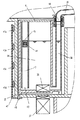
蓋体28に上方部を覆われた給水タンク34は給水タンク収納部35に鉛直方向に着脱自在に収納されて、給水タンク34の底にはインペラー36が設けられ、インペラー36の下方部にはインペラー36を回転させるモータ37が配設されている。
【0028】
38は給水タンク34内に設けられた給水タンク側給水経路で、蓋体28内に設けた蓋体側給水経路39の先端部40と着脱自在に接続されている。
【0029】
給水タンク側給水経路38、蓋体側給水経路39を給水経路と呼ぶ。
【0030】
41は給水タンクの上面開口部を覆うタンク蓋である。
【0031】
42は給水タンク34内に鉛直方向に配設された管で、タンク蓋41の下面に取り付けられている。管42の下方部43は給水タンクの底付近で連通している。磁石44を内蔵したフロート45は管42内で上下運動自在に配設されている。磁石44を内蔵したフロート45の比重は水の比重より小さい値で独立発泡樹脂で形成されている。磁石44に感動するリードスイッチ46a、46b、46c、46dを管42と平行に配設してリードスイッチ取付板47に取り付けられている。リードスイッチ取付板47は給水タンク収納部35の外側にネジ48によって固定されている。
【0032】
最下位置にあるリードスイッチ46dはフロート45の最下点位置とほぼ同じ高さに配設されており、フロート45が最下点の位置にあるときリードスイッチ46dは感動してONになる。
【0033】
49は制御部で、米計量、米とぎ、米搬送、給水、炊飯を制御する。
【0034】
米とぎ部23は、米計量部22で計量された米を収納する米収納容器45、米収納容器50内で回転自在に配設された回転羽根51、回転羽根51を駆動する駆動手段52を備えている。
【0035】
米搬送部25は、米搬送ファン53が生み出す空気流により米を炊飯部24へ搬送する。
(実施例2)
図3は、本発明の第2の実施例の自動炊飯器の断面図である。図3において、54は自動炊飯器本体の前面部に設けた水平方向に着脱自在な給水タンクである。給水タンク54の材料は例えばアクリルなどの透明で形成されており、前面部には炊飯する米に見合う水量の水位線が印刷されている。水位線を給水タンクの表面を凸または凹のラインで形成しても支障はない。
【0036】
以上のように構成された自動炊飯器について、以下その動作、作用を説明する。
【0037】
使用者は米を貯米部21内に投入し、蓋体28を開けて給水タンク34に水を入れる。給水タンク34は着脱自在なので、給水タンク34を自動炊飯器本体20から取り出して水を入れることができる。水を入れた給水タンク34を給水タンク収納部35にセットして、蓋体28を閉める。
【0038】
次に、使用者は炊飯したい米の量を入力した後、運転開始ボタン(図示しない)を押すと、制御部49はそれぞれのリードスイッチのON−OFF状態を感知する。
【0039】
給水タンク34の水位高さにフロート44が位置しているので、そのフロートに最も近いリードスイッチがONになる。
【0040】
ONになったリードスイッチ(46aまたは46bまたは46cまたは46d)によって、フロート44の位置すなわち給水タンク34内の水量を検知することができる。
【0041】
ところが、検知した給水タンク34内の水量が使用者の炊飯したい米の量に見合う水量未満であれば、水量不足であることを報知して、運転を開始しない。
【0042】
また、最下位置にあるリードスイッチ46dがONのときは、フロート45が最下点の位置にあるときなので、給水タンク34内には水がほとんどないと判断して、同様に水量不足であることを報知して、運転を開始しない。
【0043】
そして、全てのリードスイッチがOFFのときは、給水タンク34が給水タンク収納部35に収納されていない場合か、あるいは、タンク蓋41が給水タンク34にセットされていない場合(実施例1)であるので、その旨を報知して、運転を開始しない。
【0044】
さらに、給水タンク34が給水タンク収納部35に収納されると、いずれかのリードスイッチはONになるので、いずれかのリードスイッチがONになっている時間を計測して、一定時間、例えば水の新鮮度がなくなる時間が経過したらその旨を表示して、使用者に水の交換を促す。
【0045】
水の新鮮度は外気温によって大きく変化するので、給水タンク付近に室温センサーを設けて、室温によって、報知する時間を変えることにより、気温が高い夏にはより短い時間経過でも使用者に水の交換を促すことができる。
【0046】
また、水の腐敗の恐れがある時間まで時間が経過した場合には、使用者に水の交換を促すだけではなく、その旨を報知して、運転を開始しないこともできる。
【0047】
使用者は報知内容によって、給水タンク34に水を補給したり、給水タンク34をセットしたり、あるいは給水タンク34内の水を交換する。
【0048】
その結果、給水タンク34内の水量が使用者の炊飯したい米の量に見合う水量以上であれば、自動炊飯器20の運転が開始する。
【0049】
運転が開始されると、制御部49は、まず、モータ37を動作させて、使用者が設定した炊飯量に最適な量の水を、給水タンク34から給水タンク側給水経路38、蓋体側給水経路39、蒸気口33を経て炊飯部24の鍋26へ供給する。
【0050】
次に、制御部49は米計量部22を動作させる。そして、米計量部22は、所定量の米を米収納容器45へ供給する。
【0051】
所定量の米が米収納容器50に供給されると、制御部49は米とぎ工程プログラムに従って駆動手段52を動作させる。駆動手段52が動作することにより回転羽根51が回転し、米収納容器50内に収納された米をとぐ米とぎ工程が行われる。
【0052】
米とぎ工程が終了すると、制御部49は米搬送工程プログラムに従って米搬送ファン53および米投入弁32を動作させる。そして、米とぎ部23でとがれた米を、米搬送部25を介して炊飯部24の鍋26へ供給する。
【0053】
このようにして、所定量の水と米が鍋26へ供給されると、制御部49は米に水を吸収させる浸漬工程プログラムおよび炊飯工程プログラムに従って炊飯部24を動作させる。炊飯部24が動作することにより、使用者が炊飯したい量の米が炊飯されることになる。
【0054】
なお、本実施例において、あらかじめ制御部49がそれぞれのリードスイッチのON−OFF状態を感知することによって、使用者が炊飯したい米の量を入力した前に、または、運転開始ボタンを押す前に、どれだけの炊飯量に見合う水が給水タンク34内にあるかを検知し表示することもできる。
【0055】
また、水量検知手段としては重量センサーにて水の重量を測ったり、光センサーで水位を検知する等の手段もある。
【0056】
磁石を有したフロートとリードスイッチによって、水位を検知する水量検知手段において、フロートをドーナツ状に形成し、そのフロートの中心穴にリードスイッチを配設する形態がよく知られている。しかし、フロート、リードスイッチとも給水タンク内に配置されてしまうので、給水タンクを着脱自在に収納するためにはリードスイッチの電気線をも着脱可能な接続にしなければならず、周囲に水が存在する部位であるので、信頼性確保のためにコスト高となる。それに比して、本実施例のように、リードスイッチを給水タンクの外側に備えることにより、低コストで、信頼性の高い水量検知を実現することができる。
【0057】
【発明の効果】
以上のように、本発明によれば、水量不足による炊き損じを防止することができ、また、給水工程を途中で中断するには至らないので、使用者が運転を開始させる前に、給水タンク内の水量を確認する必要がない使い勝手の優れた自動炊飯器を提供することができる。
【図面の簡単な説明】
【図1】 本発明の実施例における自動炊飯器の断面図
【図2】 本発明の実施例における自動炊飯器の給水タンクとその周辺の部分断面図
【図3】 本発明の実施例2における自動炊飯器の断面図
【図4】 従来の自動炊飯器の側面断面図
【図5】 従来の自動炊飯器の正面断面図
【符号の説明】
20 自動炊飯器本体
21 貯米部(給米部)
22 米計量部(給米部)
23 米とぎ部(給米部)
24 炊飯部
25 米搬送部(給米部)
34 給水タンク
38 給水タンク側給水経路(給水経路)
39 蓋体側給水経路(給水経路)
41 タンク蓋
42 管
44 磁石
45 フロート
46a リードスイッチ
46b リードスイッチ
46c リードスイッチ
46d リードスイッチ(最下位置)[0001]
BACKGROUND OF THE INVENTION
The present invention relates to an automatic rice cooker used for general home use or business use.
[0002]
[Prior art]
Conventionally, as an automatic rice cooker which has this kind of water tank, there exist some which are described in Japanese Patent Publication No. 7-40986, for example. 4 and 5 show a conventional automatic rice cooker described in the publication.
[0003]
4 and 5, reference numeral 1 denotes a main body cabinet. The main body cabinet 1 is provided with a drawer, and the
[0004]
Moreover, the
[0005]
In such a configuration, after keying in the amount of rice to be cooked, when the start switch is pressed, the rice in the rice bin 6 is weighed by the volume measuring unit 6a and put into the
[0006]
[Problems to be solved by the invention]
However, in the conventional configuration, since the amount of water in the water tank is not detected, it is not known whether water suitable for rice is supplied into the water tank. If the amount of water is insufficient, the rice is cooked with insufficient water and hard rice is cooked. Or in the middle of water supply to the pot of water, for example, it was detected that water was insufficient with a water supply amount sensor or the like, and it had to be interrupted without moving to the next rice cooking process. In this case, since it takes time until the water supply amount sensor detects that the water supply is insufficient by pressing the start switch, the user may not know that the water supply process has been interrupted. Before pressing the switch, there was a problem that the amount of water in the water tank had to be confirmed.
[0007]
The present invention solves the above-mentioned conventional problems, and detects the amount of water in the water tank before the user starts operation, and determines whether the water in the water tank is suitable for the rice to be cooked. It is possible to prevent the cooking loss due to insufficient water amount. In addition, since the water supply process is not interrupted, the purpose is to provide an easy-to-use automatic rice cooker that does not require the user to check the amount of water in the water tank before starting operation. It is said.
[0008]
[Means for Solving the Problems]
In order to solve the conventional problems, a rice cooking unit for cooking rice, a water supply tank for supplying water to the rice cooking unit, a water supply path for supplying water from the water supply tank to the rice cooking unit, and a water amount of the water supply tank are detected. And a water amount detecting means.
[0009]
This allows the user to detect the amount of water in the water tank before starting the operation and inform the user whether there is water in the water tank that matches the rice to be cooked. It is possible to prevent cooking failure. In addition, since the water supply process is not interrupted halfway, it is possible to provide an easy-to-use automatic rice cooker that does not require confirmation of the amount of water in the water tank before the user starts operation.
[0010]
DETAILED DESCRIPTION OF THE INVENTION
The invention according to claim 1 is a rice cooking unit for cooking rice, a water supply tank for supplying water to the rice cooking unit, a tank lid for covering an upper surface opening of the water supply tank, and water supply for detachably storing the water supply tank. A tank storage unit, a water supply path for supplying water from the water supply tank to the rice cooking unit, and water amount detection means for detecting the amount of water in the water supply tank, the water amount detection means communicating with the water supply tank in the water supply tank A pipe disposed in the vertical direction, a float provided in the pipe and having a magnet, a plurality of vertical switches provided in the water tank storage portion, and a reed switch that is moved by the magnet. , by which is attached to the lower surface of the tank lid, to detect the amount of water in the water supply tank before the user starts the operation, whether the water to meet the US to cooking is in the water supply tank It is possible to inform the user, it is possible to prevent the Sonji cook due to water shortage.
[0011]
In addition, since the water supply process is not interrupted, it is possible to provide an automatic rice cooker that is easy to use and does not require confirmation of the amount of water in the water supply tank before the user starts operation.
[0012]
In addition, since the position of the float having the magnet changes in conjunction with the amount of water in the water supply tank, the reed switch can be moved by the magnet that the float has and can detect the position of the float, that is, the amount of water.
[0013]
In addition, by providing a tank lid in the water supply tank, water in the water supply tank is not exposed to the outside world even when the lid is opened, so that intrusion of dust into the water supply tank can be prevented. In addition, rice is often spilled when the rice is ready after cooking, but since it can still be prevented from falling into the water supply tank, hygienic clean water can be obtained.
[0014]
In addition, since the magnet is attached to the tank lid, all the reed switches are turned off unless the tank lid is set in the water supply tank, so that it is possible to notify if the user forgets to set the tank lid. Therefore, it is possible to prevent the user from cooking without setting the tank lid.
[0015]
In addition, by providing multiple reed switches in the vertical direction, the position of the float with built-in magnet can be detected in fine units, so it is possible to determine whether there is an amount of water that matches the amount of rice to be cooked. You can find out at
[0016]
For example, in the case of a rice cooker that can cook 1 cup (0.18L) to 5 cups (0.9L), only one reed switch is limited to two-stage detection with a large or small amount of water. If set between 2 and 3 cups, even if there is water in the water supply tank that is suitable for 4 cups of rice, there is no water in the water supply tank that is suitable for 5 cups of rice. I have to do it.
[0017]
However, by providing five reed switches, it is possible to detect a total of six levels, less than one cup and the number of each cup, so whether or not there is water in the water supply tank that is suitable for rice to be cooked in units of each cup. I can know.
[0018]
The invention according to
[0019]
The invention according to
[0020]
In addition, since the water supply process is not interrupted, it is possible to provide an automatic rice cooker that is easy to use and does not require confirmation of the amount of water in the water supply tank before the user starts operation.
[0021]
Moreover, when setting a water supply tank, it is not necessary to lift a water supply tank higher than what was comprised detachably in the perpendicular direction, and can be set easily. Moreover, since the amount of water in the water supply tank can be seen from the lateral direction by forming the water supply tank with a transparent material, the user can know the outline of the amount of water in the water supply tank. Furthermore, by providing a water level line corresponding to the amount of rice to be cooked in the water supply tank, the user can know in advance whether the amount of water is excessive or insufficient.
[0022]
The invention according to
[0023]
The invention according to
[0024]
【Example】
Embodiments of the present invention will be described below with reference to the drawings.
Example 1
The automatic rice cooker
[0025]
[0026]
A
[0027]
The
[0028]
A water supply tank side
[0029]
The water supply tank side
[0030]
41 is a tank cover which covers the upper surface opening part of a water supply tank.
[0031]
[0032]
The
[0033]
49 is a control part, and controls rice measurement, rice cutting, rice conveyance, water supply, and rice cooking.
[0034]
The
[0035]
The
(Example 2)
FIG. 3 is a sectional view of an automatic rice cooker according to the second embodiment of the present invention. In FIG. 3, 54 is a water supply tank that is detachable in the horizontal direction and is provided on the front surface of the main body of the automatic rice cooker. The material of the
[0036]
About the automatic rice cooker comprised as mentioned above, the operation | movement and an effect | action are demonstrated below.
[0037]
The user puts rice into the
[0038]
Next, after the user inputs the amount of rice to be cooked and presses an operation start button (not shown), the
[0039]
Since the
[0040]
The position of the
[0041]
However, if the detected amount of water in the
[0042]
Further, when the
[0043]
When all the reed switches are OFF, the
[0044]
Further, when the
[0045]
Since the freshness of water varies greatly depending on the outside air temperature, a room temperature sensor is installed near the water supply tank, and the alarm time is changed depending on the room temperature. Can be exchanged.
[0046]
In addition, when the time has passed until there is a risk of water decay, not only is the user prompted to exchange water, but the user can be informed and the operation can not be started.
[0047]
The user replenishes the
[0048]
As a result, if the amount of water in the
[0049]
When the operation is started, first, the
[0050]
Next, the
[0051]
When a predetermined amount of rice is supplied to the
[0052]
When the rice cutting process is completed, the
[0053]
In this way, when a predetermined amount of water and rice are supplied to the
[0054]
In this embodiment, the
[0055]
Further, as the water amount detecting means, there are means such as measuring the weight of water with a weight sensor and detecting the water level with an optical sensor.
[0056]
In a water amount detection means for detecting a water level by a float having a magnet and a reed switch, a form in which a float is formed in a donut shape and a reed switch is disposed in the center hole of the float is well known. However, since both float and reed switch are placed in the water supply tank, in order to detachably store the water supply tank, the electrical wire of the reed switch must be detachable, and there is water around it. Therefore, the cost is increased to ensure reliability. In contrast, by providing the reed switch outside the water supply tank as in the present embodiment, it is possible to realize highly reliable water amount detection at low cost.
[0057]
【The invention's effect】
As described above, according to the present invention, it is possible to prevent cooking failure due to insufficient amount of water, and since the water supply process is not interrupted halfway, before the user starts operation, the water supply tank It is possible to provide an easy-to-use automatic rice cooker that does not require confirmation of the amount of water inside.
[Brief description of the drawings]
FIG. 1 is a cross-sectional view of an automatic rice cooker in an embodiment of the present invention. FIG. 2 is a partial cross-sectional view of a water supply tank of the automatic rice cooker and its surroundings in an embodiment of the present invention. Cross-sectional view of an automatic rice cooker [Fig. 4] Cross-sectional side view of a conventional automatic rice cooker [Fig. 5] Front cross-sectional view of a conventional automatic rice cooker [Explanation of symbols]
20 Automatic
22 Rice Weighing Department (rice supply department)
23 Rice Togi Department (rice supply department)
24
34
39 Lid side water supply route (water supply route)
41
Claims (5)
Priority Applications (1)
| Application Number | Priority Date | Filing Date | Title |
|---|---|---|---|
| JP2002135115A JP3801093B2 (en) | 2002-05-10 | 2002-05-10 | Automatic rice cooker |
Applications Claiming Priority (1)
| Application Number | Priority Date | Filing Date | Title |
|---|---|---|---|
| JP2002135115A JP3801093B2 (en) | 2002-05-10 | 2002-05-10 | Automatic rice cooker |
Publications (2)
| Publication Number | Publication Date |
|---|---|
| JP2003325320A JP2003325320A (en) | 2003-11-18 |
| JP3801093B2 true JP3801093B2 (en) | 2006-07-26 |
Family
ID=29697522
Family Applications (1)
| Application Number | Title | Priority Date | Filing Date |
|---|---|---|---|
| JP2002135115A Expired - Fee Related JP3801093B2 (en) | 2002-05-10 | 2002-05-10 | Automatic rice cooker |
Country Status (1)
| Country | Link |
|---|---|
| JP (1) | JP3801093B2 (en) |
Families Citing this family (9)
| Publication number | Priority date | Publication date | Assignee | Title |
|---|---|---|---|---|
| JP4722145B2 (en) * | 2008-01-25 | 2011-07-13 | 三菱電機株式会社 | Steam recovery cooker |
| JP5247292B2 (en) * | 2008-08-08 | 2013-07-24 | 三菱電機株式会社 | rice cooker |
| JP2010207638A (en) * | 2010-06-30 | 2010-09-24 | Mitsubishi Electric Corp | Heating cooker |
| JP4980448B2 (en) * | 2010-06-30 | 2012-07-18 | 三菱電機株式会社 | Cooker |
| JP4980447B2 (en) * | 2010-06-30 | 2012-07-18 | 三菱電機株式会社 | Cooker |
| JP5143190B2 (en) * | 2010-06-30 | 2013-02-13 | 三菱電機株式会社 | Cooker |
| CN104865857B (en) * | 2015-05-04 | 2018-02-02 | 小米科技有限责任公司 | Start the method and device of rice cooker |
| JP7386428B2 (en) * | 2020-01-23 | 2023-11-27 | パナソニックIpマネジメント株式会社 | rice cooker |
| CN214284429U (en) * | 2020-01-23 | 2021-09-28 | 松下知识产权经营株式会社 | Rice cooker |
-
2002
- 2002-05-10 JP JP2002135115A patent/JP3801093B2/en not_active Expired - Fee Related
Also Published As
| Publication number | Publication date |
|---|---|
| JP2003325320A (en) | 2003-11-18 |
Similar Documents
| Publication | Publication Date | Title |
|---|---|---|
| US9402406B2 (en) | Beverage brewer with flavor base removal | |
| CA2799844C (en) | Remote controlled food processor | |
| KR930003091B1 (en) | Automatic cooking apparatus | |
| JP3801093B2 (en) | Automatic rice cooker | |
| KR20140126515A (en) | Vending machine for cooking noodle and method for controlling the same | |
| US20170135514A1 (en) | Hot Beverage Brewer for Multiple Volumes | |
| JP2004065537A (en) | Automatic rice cooker | |
| CN219479830U (en) | Coffee machine with liquid level detection structure | |
| JP3735055B2 (en) | Wash-free rice and water supply / reduction device | |
| JP2016077662A (en) | rice cooker | |
| CN211961721U (en) | Cooking utensil | |
| CN220308915U (en) | Water purifying and drinking machine with tea making function | |
| JP3576856B2 (en) | Rice cooker | |
| CN219048052U (en) | Cooking apparatus | |
| CN211795803U (en) | Electric cooker with weighing function | |
| JP3826843B2 (en) | Rice cooker and automatic rice cooker | |
| JP2000237049A (en) | Rice cooking device | |
| JP2877757B2 (en) | Rice cooker | |
| JPH09108103A (en) | Rice washing and cooking device provided with rice polishing function | |
| JPH0390110A (en) | Automatic rice cooking device | |
| JP2004065548A (en) | Rice cooker and automatic rice cooker | |
| JP2022162217A (en) | Food supply dispenser, food supply device, food supply method, and program | |
| CN113455919A (en) | Control method for cooking appliance, cooking appliance and control system | |
| WO2005099532A1 (en) | Machine for preparing ready-to-eat meals based on pasta starting from precooked and deep-freezed pasta | |
| CN114680637A (en) | Control method for cooking appliance and cooking appliance |
Legal Events
| Date | Code | Title | Description |
|---|---|---|---|
| A621 | Written request for application examination |
Free format text: JAPANESE INTERMEDIATE CODE: A621 Effective date: 20040924 |
|
| RD01 | Notification of change of attorney |
Free format text: JAPANESE INTERMEDIATE CODE: A7421 Effective date: 20050706 |
|
| A977 | Report on retrieval |
Free format text: JAPANESE INTERMEDIATE CODE: A971007 Effective date: 20051216 |
|
| A131 | Notification of reasons for refusal |
Free format text: JAPANESE INTERMEDIATE CODE: A131 Effective date: 20051227 |
|
| A521 | Written amendment |
Free format text: JAPANESE INTERMEDIATE CODE: A523 Effective date: 20060203 |
|
| TRDD | Decision of grant or rejection written | ||
| A01 | Written decision to grant a patent or to grant a registration (utility model) |
Free format text: JAPANESE INTERMEDIATE CODE: A01 Effective date: 20060411 |
|
| A61 | First payment of annual fees (during grant procedure) |
Free format text: JAPANESE INTERMEDIATE CODE: A61 Effective date: 20060424 |
|
| R151 | Written notification of patent or utility model registration |
Ref document number: 3801093 Country of ref document: JP Free format text: JAPANESE INTERMEDIATE CODE: R151 |
|
| FPAY | Renewal fee payment (event date is renewal date of database) |
Free format text: PAYMENT UNTIL: 20100512 Year of fee payment: 4 |
|
| FPAY | Renewal fee payment (event date is renewal date of database) |
Free format text: PAYMENT UNTIL: 20110512 Year of fee payment: 5 |
|
| FPAY | Renewal fee payment (event date is renewal date of database) |
Free format text: PAYMENT UNTIL: 20120512 Year of fee payment: 6 |
|
| FPAY | Renewal fee payment (event date is renewal date of database) |
Free format text: PAYMENT UNTIL: 20130512 Year of fee payment: 7 |
|
| FPAY | Renewal fee payment (event date is renewal date of database) |
Free format text: PAYMENT UNTIL: 20130512 Year of fee payment: 7 |
|
| FPAY | Renewal fee payment (event date is renewal date of database) |
Free format text: PAYMENT UNTIL: 20140512 Year of fee payment: 8 |
|
| LAPS | Cancellation because of no payment of annual fees |