JP3796238B2 - An axial air gap type coreless vibration motor having the same type rotor as the mold type eccentric rotor - Google Patents
An axial air gap type coreless vibration motor having the same type rotor as the mold type eccentric rotor Download PDFInfo
- Publication number
- JP3796238B2 JP3796238B2 JP2003321577A JP2003321577A JP3796238B2 JP 3796238 B2 JP3796238 B2 JP 3796238B2 JP 2003321577 A JP2003321577 A JP 2003321577A JP 2003321577 A JP2003321577 A JP 2003321577A JP 3796238 B2 JP3796238 B2 JP 3796238B2
- Authority
- JP
- Japan
- Prior art keywords
- air
- core armature
- type
- eccentric rotor
- eccentric
- Prior art date
- Legal status (The legal status is an assumption and is not a legal conclusion. Google has not performed a legal analysis and makes no representation as to the accuracy of the status listed.)
- Expired - Fee Related
Links
Images


Description
この発明は、移動体通信機器のサイレントコール手段などに用いられるモールド型偏心ロータの耐衝撃性の改良に係り、同ロータを備えた扁平で薄型な軸方向空隙型コアレス振動モータに関する。 The present invention relates to an improvement in impact resistance of a mold type eccentric rotor used for silent call means of a mobile communication device and the like, and relates to a flat and thin axial gap type coreless vibration motor provided with the rotor.
偏心ロータ、特に移動体通信装置の無音報知手段等に用いられる薄型な軸方向空隙型モータに使用するコアレス型偏心ロータは、コアレス型で0.8mm以下の極めて薄いものとなり、落下などの衝撃に耐えられるように電機子コイル自体を樹脂で一体成形したもの、すなわち、空心電機子コイルを印刷配線板と共に樹脂で一体成形することによって強度を得るようにしたものが多用される。
しかも、このような偏心ロータとして小型なものほど、空隙ロスを避けねばならず、可及的に電機子コイルの一面は樹脂で覆うことなく露出されるようになっている。(特許文献1参照)
しかしながら、電機子コイルの一面を露出させるように射出金型で押さえる場合、巻始め端末がコイル辺に押し潰され、ショート、断線などの問題が発生する。
The coreless type eccentric rotor used for the eccentric rotor, especially the thin axial gap type motor used for the silence notification means of mobile communication devices, etc., is a coreless type with an extremely thin thickness of 0.8 mm or less. The one that the armature coil itself is integrally molded with resin so that it can withstand, that is, the one that obtains strength by integrally molding the air-core armature coil with resin together with the printed wiring board is often used.
Moreover, the smaller the eccentric rotor, the more the gap loss must be avoided, and as much as possible, one surface of the armature coil is exposed without being covered with resin. (See Patent Document 1)
However, when pressing with an injection mold so that one surface of the armature coil is exposed, the winding start terminal is crushed by the coil side, causing problems such as short circuit and disconnection.
このようなコイル端末のショート、断線などの問題を防ぐ手段として、ロータでは、空心コイルを載置した金属製のフレームの該コイル辺の下方に設けた凹所に端末を通して該金属フレームに接続されたものがある。(特許文献2参照)
しかしながら、このものは、樹脂で成型するものでなく金属フレームがあるので薄型化は期待できない。
However, this product is not molded with resin and has a metal frame, so it cannot be expected to be thin.
また、このような振動モータは携帯電話機等の移動体通信装置に搭載される場合、サイズが極限まで薄く直径も10mm程度の小型化が要求され、その結果コイル自体で偏心ロータを構成するものでは振動量が少なく、タングステン合金製の偏心ウエイトを使用せざるを得ない。また、軸も0.6mm以下のものが採用せざるを得ないようになっているので、耐衝撃性に十分配慮しなくてはならない。特にモータが搭載された機器が不用意に落下させてしまう場合、モータ等の電子部材については、搭載されるべき機器の重量が関与して打ち所によっては自らの重量の10000倍程度の衝撃を受けるおそれがあり、小型でタングステン合金製の偏心ウエイトを樹脂に一体成形したものでは、この偏心ウエイトの重量による樹脂の破損の対策が重要となっている。 In addition, when such a vibration motor is mounted on a mobile communication device such as a cellular phone, it is required to be as small as possible in size and about 10 mm in diameter, and as a result, the coil itself does not constitute an eccentric rotor. The amount of vibration is small, and an eccentric weight made of tungsten alloy must be used. Also, since the shaft must be 0.6 mm or less, the impact resistance must be fully considered. In particular, when a device on which a motor is mounted is inadvertently dropped, an electronic member such as a motor receives an impact of about 10,000 times its own weight depending on the weight of the device to be mounted depending on the weight of the device to be mounted. There is a fear, and in the case of a small-sized eccentric weight made of a tungsten alloy and integrally molded with a resin, it is important to take measures against damage to the resin due to the weight of the eccentric weight.
この 発明の目的は、厚みや特性を犠牲にすることなく落下などの耐衝撃性を確実に対策した偏心ロータが得られ、このような偏心ロータを組みあわせて軸方向空隙型モータの構成として極めて薄型なものを実現させるものである。 An object of the present invention is to provide an eccentric rotor that reliably takes measures against impact resistance such as dropping without sacrificing thickness and characteristics, and combining such eccentric rotors is extremely useful as a configuration of an axial gap motor. A thin one is realized.
上記課題を解決する基本的な手段としては、請求項1に示す発明のように印刷配線板(1、11)は第1面側(1a)に半径方向外方に所定の開角で形成した少なくとも二つの空心電機子コイル載置エリア(1h、1n)があり、さらに、この空心電機子コイル載置エリアの間に形成された端末結線ランド(1t)が設けられ、第2面側(1b)で回転中心から半径方向外方に複数個の整流子セグメントからなる整流子(1S)が形成され、前記空心電機子コイル載置エリアに少なくとも二つの巻線型空心電機子コイル(2A、2B)が偏心して配され、その巻始め端末が端末結線ランド(1r)に接続されると共に巻き終わり端末が端末結線ランド(1t)に接続され、タングステン合金製の偏心ウエイト(4)が回転中心を介して前記巻線型空心電機子コイルの反対側に該空心電機子コイルと共に1.8以下の比重がある樹脂(5)で前記印刷配線板に前記回転中心の位置に配された含油軸受(3)を含んで一体化されたもので、平面視で前記偏心ウエイトの外周部分を回り込んで前記巻線型空心電機子コイルに掛かるように垂下部(5a)が同樹脂で形成され、非磁性金属からなる補強部材(C)が前記偏心ウエイトの外周部分に固着されると共に前記巻線型空心電機子コイルに掛かるように前記垂下部に骨幹として埋設されたもので達成できる。
より具体的な構成は請求項2に示す発明のように前記印刷配線板は前記偏心ウエイトの主要配置部分が削除されて非円形となっており、前記巻線空心電機子コイルは配置開角が150〜170度の2個からなり、前記補強部材は少なくとも一部が前記偏心ウエイトもしくは前記印刷配線板(11)に樹脂成形前に固着されたものにするのがよい。
さらに、請求項3に示す発明のように前記空心電機子コイル載置エリアとして複数個の巻線型空心電機子コイルの各有効導体部の半分以上を載置する領域があり、外径の一部がこの領域の外側で巻線型空心電機子コイルの内径の半径方向外側近傍で直線状に形成され、該巻線型空心電機子コイルの内径部分の位置に端末結線ランド(1r)が形成されているものにするのがよい。
そして、このような偏心ロータを振動モータにするには、請求項4に示すように請求項1〜3のいずれか1項に記載のモールド型偏心ロータ(R)と、このモールド型偏心ロータを支承する軸(8)と、この軸を支承する0.2mm以下の厚みがあるハウジング(H)と、このハウジングの一部を構成するブラケット(6)と、このブラケットに添設されたもので接着層を含めた全体の厚みが0.18mm以下のブラシベース(F)と、前記偏心ロータに空隙を介して臨ませるようにブラケットの一部に配された軸方向空隙型マグネット(9)と、該マグネットの内側で前記ブラシベースに配されたもので前記偏心ロータの整流子に摺接させると共に前記モールド型偏心ロータを前記ハウジングの一部を構成するケース側に付勢させるブラシ(10)とを備え、前記ブラシベースの一部が前記マグネットが載置された部分を横断するように前記ブラケットに設けた透孔(6b)を通ってハウジング側方に給電電極(Fa)として導出されたもので達成できる。
As a basic means for solving the above problem, as in the invention shown in
More specifically, as in the invention shown in
Further, as in the invention shown in
And in order to make such an eccentric rotor into a vibration motor, as shown in
請求項1の発明によれば、垂下部は組み合わせるマグネットの厚み内に食い込むように構成できるので、ロータ自体の実質的な厚みは増加することなく、すなわち磁気回路上の損失がなく補強部材を埋め込むことができ、この補強部材が骨幹となっているので偏心ウエイトの重量による樹脂の破損が防止できる。
請求項2の発明によれば、印刷配線板の厚み分だけ偏心ウエイトの重量が多く得られるので振動量が大にできる。
請求項3の発明によれば、耐衝撃性が改善され他偏心ロータが得られる。
請求項4の発明によれば、耐衝撃性の改善され、ブラシベースの厚みが無視できる薄型な軸固定型の軸方向空隙型コアレス振動モータが得られる。
According to the first aspect of the present invention, the drooping portion can be configured to bite into the thickness of the magnet to be combined, so that the substantial thickness of the rotor itself does not increase, that is, there is no loss on the magnetic circuit and the reinforcing member is embedded. In addition, since the reinforcing member serves as a skeleton, damage to the resin due to the weight of the eccentric weight can be prevented.
According to the invention of
According to the invention of
According to the fourth aspect of the present invention, a thin shaft-fixed axial gap type coreless vibration motor with improved impact resistance and negligible brush base thickness can be obtained.
印刷配線板に空心電機子コイルと偏心ウエイトを一体に樹脂成形する偏心ロータであって、垂下部が平面視で前記印刷配線板の外周で前記偏心ウエイトの外周部分を回り込んで前記巻線型空心電機子コイルにかかるように同樹脂で形成され、該垂下部に非磁性金属からなる補強部材が骨幹となるように前記偏心ウエイトの外周部分の固着され一部が前記巻線型空心電機子コイルに掛かるように埋設された。 An eccentric rotor for integrally resin-molding an air-core armature coil and an eccentric weight on a printed wiring board, wherein the drooping portion wraps around the outer peripheral portion of the eccentric weight at the outer periphery of the printed wiring board in a plan view. The outer peripheral portion of the eccentric weight is fixed to the winding-type air-core armature coil so that a reinforcing member made of a non-magnetic metal is formed on the hanging portion and becomes a skeleton. It was buried to hang.
次に、この発明の実施の形態の図面を説明する。
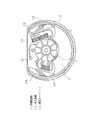
図1は本発明の偏心ロータの平面図である。(実施例1)
図2は同偏心ロータの底面図である。
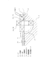
図3は図1の偏心ロータを備えた軸方向空隙型コアレス振動モータの縦断面図である。(実施例2)
図4は図1の偏心ロータの一部材の組立説明図である。
図5は図1の偏心ロータの変形例の平面図である。(実施例3)
Next, drawings of embodiments of the present invention will be described.
FIG. 1 is a plan view of an eccentric rotor of the present invention. Example 1
FIG. 2 is a bottom view of the eccentric rotor.
FIG. 3 is a longitudinal sectional view of an axial gap type coreless vibration motor provided with the eccentric rotor of FIG. (Example 2)
FIG. 4 is an assembly explanatory diagram of one member of the eccentric rotor of FIG.
FIG. 5 is a plan view of a modification of the eccentric rotor of FIG. Example 3
次に本願のモールド型偏心ロータの第1の実施例をを図1、図2によって説明する。
図1は印刷配線板の第1面側から見た平面図であり、図2は図1の裏側に相当する第2面側から見た平面図である。
印刷配線板1は第1面側1aに平面視で複数個の巻線型空心電機子コイルの各有効導体部の半分以上を160度程度の開角で載置できるように形成した領域1h、1nがあり、上方が直線状に切り欠かれ、外径の一部1c、1dがこの領域の外側で巻線型空心電機子コイルの内径の半分以上で、ほぼ前記巻線型空心電機子コイル内径の半径方向外側の円弧のあたりを接線とする直線に形成され、この内径部分に第1の端末結線部ランド1rが形成されると共に、第2の端末結線ランド1tが前記各領域間の直線部分1eに形成される。
この印刷配線板1の第2面側1bでは、回転中心と同心に複数個の整流子セグメントからなる整流子1Sが印刷形成されて表面が金メッキされている。前記第1面の各領域に巻線型空心電機子コイル2A、2Bが載置されて巻始め端末2a、2bが前記第1の端末結線用ランド1rに接続されると共に、巻き終わり端末が前記第2の端末結線ランド1tに接続され、該巻線型空心電機子コイル2A、2Bの外径を覆うように前記印刷配線板1に樹脂5で一体化されるようになっている。
ここで、前記巻線型空心電機子コイル2A、2Bの巻始め端末2a、2bを前記第1の端末結線ランドに接続手段としては、図3に示すようなジグを利用する。すなわち、ジグJは、前記印刷配線板1が載置される平坦部分Jaと、この印刷配線板1の直線で形成された外径の一部1c、1dのところが各空心電機子コイル2A、2Bの外側の無効導体部分の形状に合わせて彫り込まれた凹所Jbが形成されたもので、このジグJを使用するには、この凹所Jbに前記各空心電機子コイル2A、2Bを立てて収め、巻始め端末2a、2bを前記第1の端末結線用ランド1rに半田付し、その後、前記外径の一部1c、1dを支点として該各空心電機子コイル2A、2Bを90度回転して想像線で示すように前記領域1h、1nに寝かせて接着するようにすればよい。もし該コイルの外径がかなりばらつくなら、接着剤が硬化する前に、さらに、必要に応じて抜け止めピンJdで支持された可動部材Jcをスライドさせて該コイルの外形を合わせるようにして載置する位置を一定にすることもできる。
このようにすれば、内径の小さい空心電機子コイルでも無理に半田こてを入れなくて済むので、巻始め端末の結線処理が容易にでき、空心電機子コイルはサイズがばらついても外径の位置が一定になるので、樹脂成形時に該コイルの外径に回り込む樹脂の量が一定にでき、強度的に安定する。
その後、巻き終わり端末が前記第2の端末結線ランド1tに半田接続されるが、この部分は、巻線型空心電機子コイル2A、2Bはオーバーラップしないように離れているので、半田こてによる半田付は容易にできる。
Next, a first embodiment of the mold type eccentric rotor of the present application will be described with reference to FIGS.
1 is a plan view seen from the first surface side of the printed wiring board, and FIG. 2 is a plan view seen from the second surface side corresponding to the back side of FIG.
The printed
On the second surface side 1b of the printed
Here, a jig as shown in FIG. 3 is used as means for connecting the winding start terminals 2a and 2b of the wound air-
In this way, even an air-core armature coil with a small inner diameter does not need to be forced to insert a soldering iron, so it is easy to connect the winding start terminal, and the air-core armature coil has an outer Since the position is constant, the amount of resin that wraps around the outer diameter of the coil during resin molding can be made constant, and the strength is stable.
Thereafter, the winding end terminal is soldered to the second terminal connection land 1t, but this portion is separated so as not to overlap the winding type air-
前記印刷配線板1は、ロータ自体で振動を発生させるために、回転中心を介して前記空心電機子コイル反対側の広い方が欠除されていて非円形となっており、この欠除された部分に比重15以上で軸方向抜け止め手段として第1、第2の段部4a、4bが設けられたタングステン合金製の偏心ウエイト4が配され、前記印刷配線板1、空心電機子コイル2A、2Bと共に比重1.8以下の樹脂5で一体化され、偏心ロータRに構成されている。
この偏心ロータRには、さらに回転中心に1個の焼結含油軸受3が備えられる。この焼結含油軸受3は樹脂Jで一体成形しても、あるいは樹脂成形後、圧入などで嵌着する手段を採用しても良い。
前記樹脂5の外周部分には、樹脂の部分の断面積を少しでも大にして強度を出すために垂下部5aが形成される。この垂下部5aは、前記偏心ウエイト4の弧状部から前記空心電機子コイル2A、2Bまで平面視で重畳するように掛かって形成される。
この偏心ウエイト4には、平面視で馬蹄型の補強部材Cが外周にスポット溶接などの手段で固着される。この補強部材は堅さを得るためにばね性で非磁性のステンレス材からなる。この補強部材の両端は、平面視で前記空心電機子コイル2A、2Bに一部が重畳するように掛かっている。したがって、この空心電機子コイル2A、2Bと偏心ウエイト4とは樹脂で一体成形する際に、垂下部5aに該補強部材Cが骨幹となって埋め込まれることになり、偏心ウエイトと空心電機子コイルを一体化する樹脂5が破損しにくくなる。
なお、この垂下部5aは、後記の図3に示すように組み合わせるマグネットの外周に来るようになっているので、磁気回路が犠牲となるおそれはない。
このようにすると、空心電機子コイル2A、2Bの巻き始め端末2aは、該コイルの内径内に収容されるので、射出金型から保護されるため、断線、ショートの問題が回避できる。
ここで、前記樹脂5は、重心位置をできるだけ相殺してしまわないように密度(比重)が少なく、成形性と再生性のよいポリブチレンテレフタレート樹脂など密度が1.8以下のもので、伸びと曲げ強度のバランス上から15%程度のガラス繊維の入ったものが選定される。
また、この偏心ウエイト4には、モータサイズ、たとえば直径14mm〜10mmなどに応動して消費電流と遠心力を勘案して密度(比重)が17〜18.4のものが選定される。
前記焼結含油軸受3は、図3に示すように円筒形状で印刷配線板1の中心位置に設けられ、後述の軸8により偏心ロータRがブラケット7へ回転自在に支持される。また、この焼結含油軸受3の軸方向中央部には、外周に凸部3aが設けられている。この凸部3aにより焼結含油軸受3はモールド成形後、偏心ロータRに対する軸方向への抜け強度を増強することができる。
また、凸部3aは筒状の焼結含油軸受3の外周全周に亘らず断続して形成しても同様の効果が得られ、このようにすれば、回転方向に対する取り付け強度も強くすることができる。
The printed
The eccentric rotor R is further provided with one sintered oil-impregnated
A drooping
On the
In addition, since this
In this way, since the winding start terminal 2a of the air-
Here, the
The
As shown in FIG. 3, the sintered oil-impregnated
Further, the same effect can be obtained even if the convex portion 3a is intermittently formed not over the entire outer periphery of the cylindrical sintered oil-impregnated
このようにした偏心ロータRは、図3に示すような軸方向空隙型コアレスモータとして活用される。すなわち、偏心ロータRは、前記焼結含油軸受3を介してブラケット6の中心に設けたバーリング部6aに基端が圧入固着された軸8に回転自在に装着され、前記ブラケット6とケース7からなるハウジングHに格納される。
このハウジングHは薄型でしかも強度があるように構成するために厚みが0.2mm以下、好ましくは0.15mm〜0.1mmに磁性ステンレスで構成される。前記偏心ロータRは、該ブラケット6に配されたリング状の軸方向空隙型マグネット9の磁界を軸方向空隙を介して受ける。このマグネットの内径部でフレキシブルブラシベースFに配された一対のブラシ10、10によって前記整流子Sを介して電力を受けるようになっている。ここで、該フレキシブルベースFはポリエステルあるいはポリイミドフイルムからなり、厚みがのりを含めて0.18mm程度のものが選定される。
前記ブラケット6には、前記マグネット9が載置された部分を横断するように透孔6bが設けられ、前記ブラシベースFの一部が半径方向に延ばされ、この透孔6aを通って側方に給電電極Faとして導出されるようになっている。
この透孔によってブラシベースの厚みが無視できるので、モータとして薄いものが実現できる。
The eccentric rotor R thus configured is used as an axial gap type coreless motor as shown in FIG. That is, the eccentric rotor R is rotatably mounted on the
The housing H is made of magnetic stainless steel with a thickness of 0.2 mm or less, preferably 0.15 mm to 0.1 mm, so as to be thin and strong. The eccentric rotor R receives the magnetic field of the ring-shaped axial gap type magnet 9 disposed on the
The
Since the thickness of the brush base can be ignored by this through hole, a thin motor can be realized.
図5は、偏心ロータの変形例で、補強部材CCをリング状に形成し、偏心ウエイト4と印刷配線板11の全周をカバーするようにし、偏心ロータR1として円盤形に樹脂成形によって構成したもので、前図と同一な部材は同符号を付してその説明を省略する。
すなわち、ここで印刷配線板11は図1の印刷配線板1との相違点として平面視で上方が円弧部11eになっているもので、偏心ウエイト4が格納される部分は削除されて非円形になっているには変わりがない。円弧部11eによって前記のような垂下部55aは、マグネットに当たらないように全周に形成することができる。
前記補強部材CCは、ここでは非磁性の厚みが0.3mm程度のばね性洋白材からなるもので平面視でリング状に形成され、前記偏心ウエイト4の外周にスポット溶接などの手段で固着されると共に前記円弧部11eに形成したランド11gに半田付で固着される。
その後、この補強部材CCは、印刷配線板11、空心電機子コイル2A、2B及び偏心ウエイト4を樹脂55で一体に成形する際に垂下部55aに埋め込まれる。
このようにすれば、偏心ウエイト4に固着された補強部材CCは、平面視で前記空心電機子コイル2A、2Bに一部が重畳するように掛かり、前記印刷配線板のランド11gにも固着されているので該補強部材CCが強い骨幹となり、偏心ウエイトの重量が大きくなっても樹脂55が破損しにくくなる。
FIG. 5 is a modification of the eccentric rotor, in which the reinforcing member CC is formed in a ring shape so as to cover the entire circumference of the
That is, here, the printed
Here, the reinforcing member CC is made of a springy white material having a nonmagnetic thickness of about 0.3 mm and is formed in a ring shape in plan view, and is fixed to the outer periphery of the
Thereafter, the reinforcing member CC is embedded in the hanging portion 55a when the printed
In this way, the reinforcing member CC fixed to the
この発明によるモールド型偏心ロータは、上述のように空心電機子コイル、偏心ウエイトを印刷配線板に一体にモールドする構成にして強度を十分維持できるので薄型にでき、特に軸方向空隙型コアレス振動モータに採用して極めて薄く構成できるようになり、移動体通信装置のような携帯機器に無音報知手段として産業上有意義な技術手段として奏するものである。
また、整流子として印刷配線板で形成したものを示したが、整流子セグメントは銅箔のままで別の整流子をこのセグメントに配したものでもよい。
なお、磁極の数は6極、4極でも組みあわせる軸方向空心電機子コイルに合わせて対応でき、コイルの数についても2個に限定する必要はなく、組みあわせるマグネットの磁極に合わせて、たとえば3個にも設定できる。
The mold type eccentric rotor according to the present invention can be thinned because the structure is such that the air-core armature coil and the eccentric weight are integrally molded on the printed wiring board as described above, so that the strength can be sufficiently reduced, and particularly the axial gap coreless vibration motor. Therefore, it can be configured to be extremely thin and can be used as an industrially meaningful technical means as a silent notification means for portable devices such as mobile communication devices.
Moreover, although what was formed with the printed wiring board as a commutator was shown, the commutator segment may arrange | position another commutator to this segment with a copper foil.
The number of magnetic poles can be adjusted according to the axial air-core armature coil to be combined even with 6 poles or 4 poles, and the number of coils does not need to be limited to 2; according to the magnetic pole of the magnet to be combined, It can be set to three.
1、11 印刷配線板
2A、2B 空心電機子コイル
3 焼結含油軸受
4 偏心ウエイト
5、55 樹脂
6 ブラケット
7 ケース
H ハウジング
8 軸
9 マグネット
10 ブラシ
F フレキシブルベース
R、R1 偏心ロータ
1,11 Printed wiring board
2A, 2B Air-
R, R1 Eccentric rotor
Claims (4)
Priority Applications (1)
| Application Number | Priority Date | Filing Date | Title |
|---|---|---|---|
| JP2003321577A JP3796238B2 (en) | 2003-09-12 | 2003-09-12 | An axial air gap type coreless vibration motor having the same type rotor as the mold type eccentric rotor |
Applications Claiming Priority (1)
| Application Number | Priority Date | Filing Date | Title |
|---|---|---|---|
| JP2003321577A JP3796238B2 (en) | 2003-09-12 | 2003-09-12 | An axial air gap type coreless vibration motor having the same type rotor as the mold type eccentric rotor |
Publications (2)
| Publication Number | Publication Date |
|---|---|
| JP2005094844A JP2005094844A (en) | 2005-04-07 |
| JP3796238B2 true JP3796238B2 (en) | 2006-07-12 |
Family
ID=34453221
Family Applications (1)
| Application Number | Title | Priority Date | Filing Date |
|---|---|---|---|
| JP2003321577A Expired - Fee Related JP3796238B2 (en) | 2003-09-12 | 2003-09-12 | An axial air gap type coreless vibration motor having the same type rotor as the mold type eccentric rotor |
Country Status (1)
| Country | Link |
|---|---|
| JP (1) | JP3796238B2 (en) |
Families Citing this family (6)
| Publication number | Priority date | Publication date | Assignee | Title |
|---|---|---|---|---|
| KR100765111B1 (en) | 2005-07-11 | 2007-10-08 | 엘지이노텍 주식회사 | Vibration Motor |
| KR100737529B1 (en) * | 2005-09-27 | 2007-07-10 | 엘지이노텍 주식회사 | Slim type vibration motor |
| JP2007109342A (en) | 2005-10-14 | 2007-04-26 | Hitachi Global Storage Technologies Netherlands Bv | Coil-supporting structure and magnetic disk device |
| JP4921092B2 (en) * | 2006-09-26 | 2012-04-18 | 東京パーツ工業株式会社 | An axial air gap type rotor and an axial air gap type coreless motor including the rotor. |
| JP2012115108A (en) * | 2010-11-26 | 2012-06-14 | Yaskawa Electric Corp | Stator of rotary electric machine and rotary electric machine |
| KR101275247B1 (en) | 2012-03-28 | 2013-06-17 | 자화전자(주) | Flexible circuit and vibration motor therewith |
-
2003
- 2003-09-12 JP JP2003321577A patent/JP3796238B2/en not_active Expired - Fee Related
Also Published As
| Publication number | Publication date |
|---|---|
| JP2005094844A (en) | 2005-04-07 |
Similar Documents
| Publication | Publication Date | Title |
|---|---|---|
| US6600245B1 (en) | Vibration motor | |
| KR100297336B1 (en) | Eccentric commutator, manufacturing method thereof and flat coreless vibrator motor using the eccentric commutator | |
| US6765331B2 (en) | Eccentric rotor having high density member, manufacturing method thereof, and flat coreless vibrator motor using the eccentric rotor | |
| JP3796238B2 (en) | An axial air gap type coreless vibration motor having the same type rotor as the mold type eccentric rotor | |
| JP3628989B2 (en) | Disc-shaped eccentric rotor and flat vibration motor having the same | |
| JP3560601B1 (en) | Molded eccentric rotor and axial gap type coreless vibration motor having the same rotor | |
| JP5254312B2 (en) | motor | |
| JP3472761B2 (en) | Small brushless vibration motor | |
| JP3706016B2 (en) | Flat small brushless vibration motor | |
| JP4958940B2 (en) | motor | |
| JP3894368B2 (en) | Motor armature, axial gap motor with the same armature | |
| JP6049678B2 (en) | motor | |
| JP3572484B2 (en) | Eccentric rotor with high-density member, manufacturing method of the rotor, and flat coreless vibration motor using the rotor | |
| JP2009005491A (en) | Axial air-gap type coreless vibration motor | |
| JP2005218206A (en) | Eccentric rotor and vibration motor using the eccentric rotor | |
| JP3948626B2 (en) | Eccentric rotor and vibration motor using the eccentric rotor | |
| JP3530182B1 (en) | Coreless motor rotor, method of manufacturing the rotor, and axial gap type coreless motor provided with the rotor | |
| JP3759092B2 (en) | Flat coreless vibration motor equipped with an eccentric rotor and the same rotor | |
| JP2005012935A (en) | Molded eccentric rotor, and axial air-gap type coreless vibrating motor equipped with that rotor | |
| JP3357355B2 (en) | Disc-shaped eccentric rotor and flat type vibration motor having the same | |
| JP3357333B2 (en) | Eccentric rotor and small vibration motor using the same eccentric rotor | |
| JP3252140B1 (en) | Eccentric rotor and flat type vibration motor provided with the rotor | |
| JP3493352B2 (en) | Eccentric rotor having high-density member, manufacturing method of the rotor, and flat coreless vibration motor using the rotor | |
| JP3913214B2 (en) | Eccentric rotor and vibration motor using the eccentric rotor | |
| JP3527775B2 (en) | Cup type coreless motor |
Legal Events
| Date | Code | Title | Description |
|---|---|---|---|
| A977 | Report on retrieval |
Free format text: JAPANESE INTERMEDIATE CODE: A971007 Effective date: 20060303 |
|
| TRDD | Decision of grant or rejection written | ||
| A01 | Written decision to grant a patent or to grant a registration (utility model) |
Free format text: JAPANESE INTERMEDIATE CODE: A01 Effective date: 20060411 |
|
| A61 | First payment of annual fees (during grant procedure) |
Free format text: JAPANESE INTERMEDIATE CODE: A61 Effective date: 20060414 |
|
| R150 | Certificate of patent or registration of utility model |
Free format text: JAPANESE INTERMEDIATE CODE: R150 |
|
| LAPS | Cancellation because of no payment of annual fees |