JP3780828B2 - Hydraulic oil tank - Google Patents
Hydraulic oil tank Download PDFInfo
- Publication number
- JP3780828B2 JP3780828B2 JP2000208379A JP2000208379A JP3780828B2 JP 3780828 B2 JP3780828 B2 JP 3780828B2 JP 2000208379 A JP2000208379 A JP 2000208379A JP 2000208379 A JP2000208379 A JP 2000208379A JP 3780828 B2 JP3780828 B2 JP 3780828B2
- Authority
- JP
- Japan
- Prior art keywords
- filter
- tank
- chamber
- hydraulic oil
- base plate
- Prior art date
- Legal status (The legal status is an assumption and is not a legal conclusion. Google has not performed a legal analysis and makes no representation as to the accuracy of the status listed.)
- Expired - Fee Related
Links
Images


Description
【0001】
【発明の属する技術分野】
本発明は、油圧ショベル等、油圧式建設機械に設けられる作動油タンクに関するものである。
【0002】
【従来の技術】
作動油タンクは、油圧ポンプ及び油圧アクチュエータを含む油圧回路の一部を構成する機器である。作動油は、まず作動油タンクから油圧ポンプに吸い込まれて加圧される。そして、この油圧ポンプからの吐出油は方向切換弁を介して油圧シリンダなり油圧モータなりといった油圧アクチュエータに供給される。油圧アクチュエータからの戻り油はオイルクーラ等の機器を経て作動油タンク内に還流する。このように、作動油は閉鎖ループ内を循環することから、この作動油の循環中に汚損物が混入することがある。この汚損物の代表的なものとしては、金属摩耗粉であり、またシール破片等も作動油に対する汚損物となる。このような汚損物が循環すると、油圧ポンプや油圧モータ、油圧シリンダ等の機器を損傷させるおそれがあり、また各部における油漏れが生じることにもなる。
【0003】
以上の点を考慮して、作動油タンクにはフルフローフィルタからなるオイルフィルタが設けられており、このオイルフィルタにより金属摩耗粉やシール破片等の異物を除去するようにしている。そこで、従来技術の作動油タンクの構成を図5示す。
【0004】
図中において、1はタンク本体を示し、このタンク本体1は、底面部1aと四周の側面部1b及び天板部1cとから構成される密閉容器である。このようにして密閉されたタンク本体1の内部には隔壁2が設けられており、この隔壁2により流入室3と流出室4とに区画形成されている。そして、この隔壁2には、流入室3と流出室4との間に作動油が流れる流通口5が設けられている。ここで、タンク本体1を2室に区画形成したのは、戻り油に気泡が含まれている場合に、流入室3内に所定の時間だけ作動油が滞留させて空気を分離するようになし、また流出室4側の液面が大きく変動するのを防止するためである。
【0005】
タンク本体1内には、その流入室3側に複数のオイルフィルタ10が設置されている。オイルフィルタ10は、有底筒状の容器からなるフィルタケース11を有し、このフィルタケース11の内部には円環状の部材からなるフィルタエレメント12が設けられており、このフィルタエレメント12の内部スペースには流出用配管13が臨むように設けられている。そして、この流出用配管13は、フィルタケース11の底面板11aに固定されて、下方向けてに延在されている。また、図示は省略するが、フィルタケース11には油圧アクチュエータ等からの戻り油が流入する流入配管が接続されている。従って、この流入配管からフィルタケース11におけるフィルタエレメント12の外側に流入した戻り油は、フィルタエレメント12を通過する間に金属摩耗粉やシール破片等の異物が除去されて、このフィルタエレメント12の内側に流入する。このようにフィルタエレメント12の内部に流入され、異物が除去された作動油は、流出用配管13により流入室3内に導かれ、さらに流通口5を経て隔壁2により区画形成されている流出室4内に流れることになる。
【0006】
フィルタエレメント12には、図6からも明らかなように、その上部位置にリリーフ弁14が設けられている。このリリーフ弁14は、円環状となったフィルタエレメント12の上面に設けた透孔(図示せず)を開閉する弁部材15と、この弁部材15が透孔を閉鎖する方向に付勢するためのばね16とを備えている。ばね16は常時には透孔を閉鎖する方向に付勢力が作用されているが、フィルタエレメント12の内外に差圧が生じると、つまりフィルタエレメント12の外の方がフィルタエレメント12の内部よりばね16で設定した圧力以上高くなると、リリーフ弁14が開いて、フィルタエレメント12を通らないで作動油がフィルタエレメント12内に流入するようになる。
【0007】
オイルフィルタ10におけるフィルタケース11の内部に設けたフィルタエレメント12は交換可能となっている。このために、天板部1cにはフィルタの取り出し口6が設けられており、この取り出し口6にはカバー7が着脱可能に装着されている。そして、取り出し口6の周囲には、枠部材8が固着して設けられており、フィルタケース11の上端部がこの枠部材8に溶接手段で固着されている。従って、オイルフィルタ10はタンク本体1の天板部1cに垂設されており、かつフィルタケース11内に設けたフィルタエレメント12とカバー7との間にはばね9が弾装されており、このばね9によって、フィルタエレメント12を位置決めすると共に、このフィルタエレメント12をフィルタケース11の底面板11aに設けたラバー(図示せず)に圧接させて、その間を液密に保つようにしている。なお、図5において、17は油圧ポンプに接続される吸い込み配管、18は吸い込みフィルタである。
【0008】
【発明が解決しようとする課題】
ところで、油圧アクチュエータとして油圧シリンダを用いる場合には、その作動状態に応じて、つまりロッドが伸長状態にあるか縮小状態にあるかによって、シリンダ内の作動油の量が大きく変動する。そして、大型の油圧ショベル等の油圧式作動機械にあっては、油圧シリンダの数及び容積も大きいものが使用される。このような機械において、例えば全ての油圧シリンダが同時に縮小する方向に作動すると、作動油タンク内に一時的に大量の作動油が流入することがある。従って、作動油タンクに設けられるオイルフィルタも大型のものを用いなければならないが、オイルフィルタの共用化を図るために、標準サイズのオイルフィルタを複数設置するのが一般的である。ここで、オイルフィルタは、フィルタケースとフィルタエレメント等を含む独立した機器であり、このオイルフィルタを複数設置すると、各々のフィルタケースを溶接しなければならず、その分だけ製造工数が多くなる。しかも、装着されるオイルフィルタの数を多くすると、その分だけ作動油タンクの重量も重くなる等といった問題点がある。
【0009】
本発明は以上の点に鑑みてなされたものであって、その目的とするところは、作動油タンクに複数のオイルフィルタを装着する際に、その組み付けが容易であり、かつ作動油タンクが重量化するのを抑制できるようにすることにある。
【0010】
【課題を解決するための手段】
前述した目的を達成するために、本発明は、作動油中の異物を除去するフィルタを備えた作動油タンクにおいて、底面部と側面部と複数のフィルタエレメント挿入孔を有する天板部とからなるタンク本体と、前記タンク本体内に設けられ、タンク本体内部を流入室と流出室とに区画形成する隔壁と、前記タンク本体内の流入室側における一方のコーナ部に設けた切り欠き部と、前記切り欠き部に設けられ、前記流入室をフィルタ装着領域と貯留領域とに区画形成するベースプレートと、前記切り欠き部を塞ぐように設けた立壁板と、前記立壁板に設けられ、前記フィルタ装着領域に通ずる配管接続部と、前記ベースプレートに複数設けられ、前記フィルタ装着領域と前記貯留領域とを連通する複数の流出用配管と、前記各流出用配管に対応するように前記フィルタ装着領域内に着脱可能に設けた複数のフィルタエレメントと、前記隔壁に設けられ、前記貯留領域と前記流出室とを連通する流通口と、前記流出室に通ずるように前記タンク本体に設けた吸い込み配管とを備える構成としたものであって、第1の発明では、ベースプレートにより流入室を上部側のフィルタ装着領域と下部側の貯留領域とに区画形成され、立壁板はL字状に形成されて、切り欠き部を塞ぐようにしてベースプレート上に設ける構成としている。また、第2の発明では、ベースプレートは、切り欠き部の下部側で、流入室を部分的に覆うように設けられ、立壁板はコ字状に形成して、ベースプレート上に設けられて、流入室をフィルタ装着領域と貯留領域とに区画形成すると共に、切り欠き部を塞ぐ構成としたことを特徴とするものである。
【0011】
【発明の実施の形態】
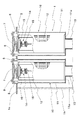
以下、本発明の実施の形態について図面を参照して詳細に説明する。まず、図1に作動油タンクの全体構成を示し、図2にその要部を拡大して示し、さらに図3にはタンク本体の要部を分解して示す。作動油タンクは、タンク本体20を有し、このタンク本体20は、底面部20aと、側面部20b及び天板部20cとから構成され、隔壁21により油圧アクチュエータからの戻り油が流入する流入室22と、汚損物が除去された作動油を油圧ポンプに向けて流出させる流出室23とを含むものであり、隔壁21には流通口24が開口している。さらに、タンク本体20の底面部20aにおける流出室23側の位置には、油圧ポンプにおける作動油の吸い込み配管25が接続されており、この吸い込み配管25には吸い込みフィルタ26が設けられている。
【0012】
流入室22は単一のチャンバとなってはおらず、ベースプレート30が設けられて、上下に2つに区画された領域を有する構成となっている。上部側の領域はフィルタ装着領域31であり、下部側の領域は汚損物が分離・除去された作動油が貯留される貯留領域32である。従って、オイルフィルタ40は、このフィルタ装着領域31に装着されている。オイルフィルタ40は、フィルタ装着領域31内に複数個、例えば2個乃至4個程度設けられる。ここで、フィルタ装着領域31に設けられるオイルフィルタ40はフィルタケースを有さないものである。従って、オイルフィルタ40は、上端部における内側にリリーフ弁41を設けたフィルタエレメント42とを有し、ベースプレート30に穿設した透孔33の内部には、フィルタエレメント42の内部空間に通じる流出用配管43が溶接等の手段により固定して設けられ、この流出用配管43はフィルタエレメント42の内部側から貯留領域32に作動油を流す流出部として機能する。
【0013】
タンク本体20の天板部20cには、各フィルタ装着部、つまりベースプレート30における透孔33を形成した位置の上部位置にカバー27が着脱可能に設けられている。そして、フィルタエレメント42は、カバー27の内面との間に設けたばね44によりベースプレート30に装着され、流出用配管43を囲繞するように配置されたラバー45に押圧されるようにして所定の位置に位置決めされた状態に固定され、かつシールされるようになっている。従って、オイルフィルタ40のタンク本体20への装着は、オイルフィルタ40をベースプレート30に固定した流出用配管42を囲繞する状態に配置され、フィルタエレメント42の上部にばね44を装着した上で、カバー27を枠部材46にボルト47により固定することにより行われる。従って、前述した従来技術のように、フィルタケースをタンク本体に溶接する必要がなくなり、その分だけオイルフィルタの組み付け工数の削減が図られて、複数設けられるオイルフィルタ40を容易に装着できる。また、カバー27を取り外すしてばね44を取り出すと、フィルタエレメント42が自由状態になるので、このフィルタエレメント42を取り出して、新たなフィルタエレメントを容易に装着することができる。
【0014】
ここで、オイルフィルタ40にはフィルタケースを備えていないが、隔壁21及びベースプレート30により流入室22はフィルタ装着領域31と貯留領域32とに分割されており、従ってこれらがタンク本体20内に設けられている全てのオイルフィルタ40に対するフィルタケースとして機能する。つまり、隔壁21は、作動油タンク内を2室に区画形成する本来の機能に加えて、オイルフィルタ40のフィルタケースとしての機能をも発揮することになる。その結果、オイルフィルタ40の構成が簡略化されると共に、軽量化も図られる。
【0015】
前述したように、タンク本体20における流入室22にベースプレート30を組み込むに当っては、図3に示したように、タンク本体20における側面部20bには、そのうちの一つのコーナ部分に所定の大きさの切り欠きCが設けられており、ベースプレート30には、この切り欠きCを設けたことにより形成される端面上に載置され、かつこの端面から僅かに外方に突出する張り出し部30aが形成されている。さらに、タンク本体30の切り欠きCの部位にはL字状に曲折した板体からなる立壁板28が装着されるようになっている。従って、ベースプレート30を切り欠きCの位置に設置して、その周囲を溶接することによりタンク本体20に固着する。その後に、立壁板28をベースプレート30の上に設置して、この立壁板28とベースプレート30及び側面部20bに溶接する。このようにしてベースプレート30を組み込んだ四周の側面部20bが形成され、その上部に天板部20cを溶接手段で固着することによって、タンク本体20が形成される。そして、作動油タンク内への戻り油を還流させるための配管接続部29は、立壁板28に取り付けることができる。
【0016】
なお、流入室はベースプレートによりフィルタ装着領域と貯留領域とが上下の2室に区画形成されるようにしているが、オイルフィルタの装着数や、戻り油の最大流量等を勘案すれば、必ずしも流入室の上部領域全体をフィルタ装着領域とする必要はない。このためには、例えば図4に示したように、タンク本体120における切り欠きC′を図3と同じ形状に設け、ベースプレート130をオイルフィルタが装着される部分とその近傍を含む限定された大きさとなし、切り欠きC′の位置に設置される立壁部128をコ字状に形成する。これによって、フィルタ装着領域のスペースを所望の広さに限定することができる。
【0017】
【発明の効果】
本発明は以上のように構成したので、作動油タンクに複数のオイルフィルタを装着する際に、その組み付けが容易であり、かつ作動油タンクが重量化するのを抑制できる等の効果を奏する。
【図面の簡単な説明】
【図1】本発明の実施の一形態を示す作動油タンクの断面図である。
【図2】図1の要部拡大図である。
【図3】ベースプレートの装着部分の分解斜視図である。
【図4】本発明における他の実施の形態を示すベースプレートの装着部分の分解斜視図である。
【図5】従来技術による作動油タンクの断面図である。
【図6】図5の要部拡大図である。
【符号の説明】
20,12 タンク本体 20a 底面部
20b 側面部 20c 天板部
21 隔壁 22 流入室
23 流出室 24 流通口
27 カバー 28,128 立壁部
30,130 ベースプレート 31 フィルタ装着領域
32 貯留領域 40 オイルフィルタ
41 リリーフ弁 42 フィルタエレメント
43 流出用配管 44 ばね[0001]
BACKGROUND OF THE INVENTION
The present invention relates to a hydraulic oil tank provided in a hydraulic construction machine such as a hydraulic excavator.
[0002]
[Prior art]
The hydraulic oil tank is a device that forms part of a hydraulic circuit including a hydraulic pump and a hydraulic actuator. The hydraulic oil is first sucked into the hydraulic pump from the hydraulic oil tank and pressurized. The oil discharged from the hydraulic pump is supplied to a hydraulic actuator such as a hydraulic cylinder or a hydraulic motor via a direction switching valve. The return oil from the hydraulic actuator flows back into the hydraulic oil tank through a device such as an oil cooler. As described above, since the hydraulic oil circulates in the closed loop, a contaminated material may be mixed during the circulation of the hydraulic oil. A typical example of this fouling material is metal wear powder, and seal fragments and the like also become fouling material for hydraulic oil. If such a pollutant circulates, there is a risk of damaging equipment such as a hydraulic pump, a hydraulic motor, a hydraulic cylinder, etc., and oil leakage may occur in each part.
[0003]
In consideration of the above points, the hydraulic oil tank is provided with an oil filter composed of a full flow filter, and foreign substances such as metal wear powder and seal debris are removed by this oil filter. FIG. 5 shows the configuration of a conventional hydraulic oil tank.
[0004]
In the figure,
[0005]
In the
[0006]
As is clear from FIG. 6, the
[0007]
The
[0008]
[Problems to be solved by the invention]
By the way, when a hydraulic cylinder is used as a hydraulic actuator, the amount of hydraulic oil in the cylinder varies greatly depending on its operating state, that is, depending on whether the rod is in an extended state or a reduced state. In a hydraulic operating machine such as a large hydraulic excavator, one having a large number and volume of hydraulic cylinders is used. In such a machine, for example, if all the hydraulic cylinders are operated in the direction of contraction simultaneously, a large amount of hydraulic oil may temporarily flow into the hydraulic oil tank. Therefore, a large oil filter provided in the hydraulic oil tank must be used, but in order to share the oil filter, it is common to install a plurality of standard size oil filters. Here, the oil filter is an independent device including a filter case, a filter element, and the like. When a plurality of oil filters are installed, each filter case must be welded, and the number of manufacturing steps increases accordingly. In addition, when the number of oil filters to be mounted is increased, there is a problem that the hydraulic oil tank becomes heavier.
[0009]
The present invention has been made in view of the above points, and an object of the present invention is to easily assemble the hydraulic oil tank when the hydraulic oil tank is attached to the hydraulic oil tank. It is to be able to suppress the conversion.
[0010]
[Means for Solving the Problems]
In order to achieve the above-described object, the present invention comprises a bottom face part, a side face part, and a top plate part having a plurality of filter element insertion holes in a hydraulic oil tank provided with a filter for removing foreign matter in the hydraulic oil. A tank body, a partition wall provided in the tank body, partitioning the inside of the tank body into an inflow chamber and an outflow chamber, a notch portion provided in one corner portion on the inflow chamber side in the tank body, A base plate provided in the notch and partitioning the inflow chamber into a filter mounting region and a storage region, a standing wall plate provided so as to close the notch, and the standing wall plate provided with the filter mounting A plurality of pipe connection portions that communicate with the area, a plurality of outlet pipes that are provided in the base plate and communicate with the filter mounting area and the storage area, and correspond to each of the outlet pipes. A plurality of filter elements detachably provided in the filter mounting region, a flow port provided in the partition wall and communicating with the storage region and the outflow chamber, and the tank body so as to communicate with the outflow chamber In the first invention, the inflow chamber is partitioned by the base plate into an upper filter mounting region and a lower storage region, and the standing wall plate is L-shaped. It is formed in a shape and is provided on the base plate so as to close the notch. In the second aspect of the invention, the base plate is provided on the lower side of the notch so as to partially cover the inflow chamber, the standing wall plate is formed in a U-shape, and is provided on the base plate. a chamber with partitions and forms the filter mounting region and the storage region, and is characterized in that it has a configuration for closing the cutout portion.
[0011]
DETAILED DESCRIPTION OF THE INVENTION
Hereinafter, embodiments of the present invention will be described in detail with reference to the drawings. First, FIG. 1 shows the entire configuration of the hydraulic oil tank, FIG. 2 shows an enlarged main portion thereof, and FIG. 3 shows an exploded main portion of the tank body. The hydraulic oil tank has a
[0012]
The inflow chamber 22 is not a single chamber, but has a structure in which a
[0013]
A
[0014]
Here, the
[0015]
As described above, when the
[0016]
The inflow chamber is divided into two upper and lower chambers by the base plate in the filter mounting area and the storage area. However, if the number of oil filters installed, the maximum flow rate of return oil, etc. are taken into account, the inflow chamber is not necessarily inflow. The entire upper region of the chamber need not be the filter mounting region. For this purpose, for example, as shown in FIG. 4, the notch C ′ in the
[0017]
【The invention's effect】
Since this invention was comprised as mentioned above, when mounting | wearing a hydraulic oil tank with a some oil filter, the assembly | attachment is easy and there exists an effect of being able to suppress that a hydraulic oil tank becomes weighty.
[Brief description of the drawings]
FIG. 1 is a sectional view of a hydraulic oil tank showing an embodiment of the present invention.
FIG. 2 is an enlarged view of a main part of FIG.
FIG. 3 is an exploded perspective view of a mounting portion of a base plate.
FIG. 4 is an exploded perspective view of a base plate mounting portion according to another embodiment of the present invention.
FIG. 5 is a cross-sectional view of a hydraulic oil tank according to the prior art.
6 is an enlarged view of a main part of FIG.
[Explanation of symbols]
20, 12
Claims (2)
Priority Applications (1)
| Application Number | Priority Date | Filing Date | Title |
|---|---|---|---|
| JP2000208379A JP3780828B2 (en) | 2000-07-10 | 2000-07-10 | Hydraulic oil tank |
Applications Claiming Priority (1)
| Application Number | Priority Date | Filing Date | Title |
|---|---|---|---|
| JP2000208379A JP3780828B2 (en) | 2000-07-10 | 2000-07-10 | Hydraulic oil tank |
Publications (3)
| Publication Number | Publication Date |
|---|---|
| JP2002021803A JP2002021803A (en) | 2002-01-23 |
| JP2002021803A5 JP2002021803A5 (en) | 2004-10-14 |
| JP3780828B2 true JP3780828B2 (en) | 2006-05-31 |
Family
ID=18704969
Family Applications (1)
| Application Number | Title | Priority Date | Filing Date |
|---|---|---|---|
| JP2000208379A Expired - Fee Related JP3780828B2 (en) | 2000-07-10 | 2000-07-10 | Hydraulic oil tank |
Country Status (1)
| Country | Link |
|---|---|
| JP (1) | JP3780828B2 (en) |
Families Citing this family (8)
| Publication number | Priority date | Publication date | Assignee | Title |
|---|---|---|---|---|
| JP4646208B2 (en) * | 2005-02-15 | 2011-03-09 | キャタピラー エス エー アール エル | Capsule filter piping structure |
| US7967980B2 (en) * | 2006-11-17 | 2011-06-28 | Kobelco Construction Machinery Co., Ltd. | Construction machine having working oil tank with filter case |
| DE102009001460B4 (en) * | 2009-03-11 | 2010-12-02 | Zf Friedrichshafen Ag | oilcontainer |
| CN106640854A (en) * | 2015-10-28 | 2017-05-10 | 中国国际海运集装箱(集团)股份有限公司 | Two-way driving ferry bus hydraulic system |
| JP6394658B2 (en) * | 2016-07-26 | 2018-09-26 | コベルコ建機株式会社 | Hydraulic oil tank |
| JP6680162B2 (en) * | 2016-09-21 | 2020-04-15 | コベルコ建機株式会社 | Hydraulic oil tank |
| WO2019017188A1 (en) | 2017-07-18 | 2019-01-24 | 株式会社クボタ | Working machine |
| CN114704511B (en) * | 2022-02-21 | 2022-12-27 | 燕山大学 | Hydraulic oil tank and hydraulic system |
-
2000
- 2000-07-10 JP JP2000208379A patent/JP3780828B2/en not_active Expired - Fee Related
Also Published As
| Publication number | Publication date |
|---|---|
| JP2002021803A (en) | 2002-01-23 |
Similar Documents
| Publication | Publication Date | Title |
|---|---|---|
| US20060219620A1 (en) | Oil pan with built-in filtering element | |
| US20090230063A1 (en) | Standpipe with integrated regulator valve | |
| CA1039207A (en) | Removable reservoir cover having internal parts of reservoir mounted thereon | |
| JP3780828B2 (en) | Hydraulic oil tank | |
| US5680847A (en) | Fuel sender for motor vehicle | |
| WO2006048976A1 (en) | Hydraulic tank | |
| KR20060088847A (en) | Filtration system with bypass valve flow control apparatus and method | |
| JP2004338565A (en) | Vehicular brake hydraulic pressure control actuator | |
| US20220106933A1 (en) | Tank device | |
| KR20190124227A (en) | Filter unit and filtration unit | |
| US11325059B2 (en) | No filter no run fluid filter with integration of low pressure fluid system | |
| EP1314896A2 (en) | Reservoir having a ventilating structure | |
| JPH0771404A (en) | Filter device for hydraulic fluid | |
| JPH1128319A (en) | Oil filter housing | |
| JP2016131972A (en) | Filter with dual pleat pack | |
| US9776110B2 (en) | Filter and method for filtration of hydraulic oil in a return line to a hydraulic tank, and a drilling rig comprising the filter | |
| JP2991456B2 (en) | Filter device | |
| JP3819235B2 (en) | Oil strainer structure for vehicles | |
| JPH10299645A (en) | Hydraulic unit | |
| JP2006046142A (en) | Filter | |
| KR20200096665A (en) | Intake filter device with air separation | |
| JP2782221B2 (en) | Reservoir tank for power steering | |
| JP2004052820A (en) | Valve body type filter and its manufacturing method | |
| JPH1182885A (en) | Float type drain trap | |
| KR960007788Y1 (en) | Mesh for oil reservoir |
Legal Events
| Date | Code | Title | Description |
|---|---|---|---|
| A131 | Notification of reasons for refusal |
Free format text: JAPANESE INTERMEDIATE CODE: A131 Effective date: 20050301 |
|
| A521 | Written amendment |
Free format text: JAPANESE INTERMEDIATE CODE: A523 Effective date: 20050421 |
|
| TRDD | Decision of grant or rejection written | ||
| A01 | Written decision to grant a patent or to grant a registration (utility model) |
Free format text: JAPANESE INTERMEDIATE CODE: A01 Effective date: 20060214 |
|
| A61 | First payment of annual fees (during grant procedure) |
Free format text: JAPANESE INTERMEDIATE CODE: A61 Effective date: 20060227 |
|
| R150 | Certificate of patent or registration of utility model |
Free format text: JAPANESE INTERMEDIATE CODE: R150 |
|
| FPAY | Renewal fee payment (event date is renewal date of database) |
Free format text: PAYMENT UNTIL: 20090317 Year of fee payment: 3 |
|
| FPAY | Renewal fee payment (event date is renewal date of database) |
Free format text: PAYMENT UNTIL: 20100317 Year of fee payment: 4 |
|
| FPAY | Renewal fee payment (event date is renewal date of database) |
Free format text: PAYMENT UNTIL: 20110317 Year of fee payment: 5 |
|
| FPAY | Renewal fee payment (event date is renewal date of database) |
Free format text: PAYMENT UNTIL: 20120317 Year of fee payment: 6 |
|
| FPAY | Renewal fee payment (event date is renewal date of database) |
Free format text: PAYMENT UNTIL: 20120317 Year of fee payment: 6 |
|
| FPAY | Renewal fee payment (event date is renewal date of database) |
Free format text: PAYMENT UNTIL: 20130317 Year of fee payment: 7 |
|
| FPAY | Renewal fee payment (event date is renewal date of database) |
Free format text: PAYMENT UNTIL: 20130317 Year of fee payment: 7 |
|
| FPAY | Renewal fee payment (event date is renewal date of database) |
Free format text: PAYMENT UNTIL: 20140317 Year of fee payment: 8 |
|
| LAPS | Cancellation because of no payment of annual fees |