JP3777862B2 - Image printing method and apparatus - Google Patents
Image printing method and apparatus Download PDFInfo
- Publication number
- JP3777862B2 JP3777862B2 JP08825099A JP8825099A JP3777862B2 JP 3777862 B2 JP3777862 B2 JP 3777862B2 JP 08825099 A JP08825099 A JP 08825099A JP 8825099 A JP8825099 A JP 8825099A JP 3777862 B2 JP3777862 B2 JP 3777862B2
- Authority
- JP
- Japan
- Prior art keywords
- color
- bar
- barcode
- image
- Prior art date
- Legal status (The legal status is an assumption and is not a legal conclusion. Google has not performed a legal analysis and makes no representation as to the accuracy of the status listed.)
- Expired - Fee Related
Links
Images


Classifications
-
- G—PHYSICS
- G06—COMPUTING; CALCULATING OR COUNTING
- G06K—GRAPHICAL DATA READING; PRESENTATION OF DATA; RECORD CARRIERS; HANDLING RECORD CARRIERS
- G06K19/00—Record carriers for use with machines and with at least a part designed to carry digital markings
- G06K19/06—Record carriers for use with machines and with at least a part designed to carry digital markings characterised by the kind of the digital marking, e.g. shape, nature, code
- G06K19/06009—Record carriers for use with machines and with at least a part designed to carry digital markings characterised by the kind of the digital marking, e.g. shape, nature, code with optically detectable marking
- G06K19/06018—Record carriers for use with machines and with at least a part designed to carry digital markings characterised by the kind of the digital marking, e.g. shape, nature, code with optically detectable marking one-dimensional coding
- G06K19/06028—Record carriers for use with machines and with at least a part designed to carry digital markings characterised by the kind of the digital marking, e.g. shape, nature, code with optically detectable marking one-dimensional coding using bar codes
-
- B—PERFORMING OPERATIONS; TRANSPORTING
- B41—PRINTING; LINING MACHINES; TYPEWRITERS; STAMPS
- B41J—TYPEWRITERS; SELECTIVE PRINTING MECHANISMS, i.e. MECHANISMS PRINTING OTHERWISE THAN FROM A FORME; CORRECTION OF TYPOGRAPHICAL ERRORS
- B41J2/00—Typewriters or selective printing mechanisms characterised by the printing or marking process for which they are designed
- B41J2/005—Typewriters or selective printing mechanisms characterised by the printing or marking process for which they are designed characterised by bringing liquid or particles selectively into contact with a printing material
- B41J2/01—Ink jet
- B41J2/21—Ink jet for multi-colour printing
-
- B—PERFORMING OPERATIONS; TRANSPORTING
- B41—PRINTING; LINING MACHINES; TYPEWRITERS; STAMPS
- B41J—TYPEWRITERS; SELECTIVE PRINTING MECHANISMS, i.e. MECHANISMS PRINTING OTHERWISE THAN FROM A FORME; CORRECTION OF TYPOGRAPHICAL ERRORS
- B41J3/00—Typewriters or selective printing or marking mechanisms characterised by the purpose for which they are constructed
- B41J3/01—Typewriters or selective printing or marking mechanisms characterised by the purpose for which they are constructed for special character, e.g. for Chinese characters or barcodes
-
- B—PERFORMING OPERATIONS; TRANSPORTING
- B41—PRINTING; LINING MACHINES; TYPEWRITERS; STAMPS
- B41J—TYPEWRITERS; SELECTIVE PRINTING MECHANISMS, i.e. MECHANISMS PRINTING OTHERWISE THAN FROM A FORME; CORRECTION OF TYPOGRAPHICAL ERRORS
- B41J3/00—Typewriters or selective printing or marking mechanisms characterised by the purpose for which they are constructed
- B41J3/407—Typewriters or selective printing or marking mechanisms characterised by the purpose for which they are constructed for marking on special material
- B41J3/4075—Tape printers; Label printers
-
- G—PHYSICS
- G06—COMPUTING; CALCULATING OR COUNTING
- G06K—GRAPHICAL DATA READING; PRESENTATION OF DATA; RECORD CARRIERS; HANDLING RECORD CARRIERS
- G06K19/00—Record carriers for use with machines and with at least a part designed to carry digital markings
- G06K19/06—Record carriers for use with machines and with at least a part designed to carry digital markings characterised by the kind of the digital marking, e.g. shape, nature, code
- G06K2019/06215—Aspects not covered by other subgroups
- G06K2019/06225—Aspects not covered by other subgroups using wavelength selection, e.g. colour code
Description
【0001】
【発明の属する技術分野】
本発明は、バーコードを表すバーコード画像を印刷する画像印刷方法およびその装置に関する。
【0002】
【従来の技術】
いわゆるバーコードとは、異なる太さ(幅)や間隔をもつ平行な(縦)線(以下「バー」という)の組合せによって、文字(英字、数字、記号等)を表現するコードであり、バーコードリーダ等に設けられたオプティカルスキャナ等の光学的な読取手段による横断走査によって、光学的に読み取れる2進情報を表す。また、誤り検出が組み込まれていて、いずれの方向からでも読み取れるものもある。そして、これらのバーコードは、ラベル等に印刷されてラベルとして書物や食品その他の商品に貼り付けられ、あるいは直接商品の表面(またはその包装等の表面)に印刷されて、図書館や病院、食料品店などにおいて、迅速に2進情報を入力する入力手段(読取手段)の入力(読み取り)対象として利用される。
【0003】
これらの場合、バーコードが表す2進情報の2値(例えば0と1)は、光の反射率の差(反射率差)により相互に区別され、反射率が低い部分(線:バー:こちら側を「黒バー」ともいう)が2値のうちの一方(例えば1)、反射率が高い部分(線:バー:こちら側を「白バー」または「スペース」ともいう)が2値のうちの他方(例えば0)と判別される(読み取られる)。このため、この読取(判別)可能な光の反射率に関する条件がバーコードの読取規格として規格化されている(図12参照)。
【0004】
【発明が解決しようとする課題】
ところで、バーコードはいわゆる画像の一種であり、画像を印刷可能なプリンタなどの印刷装置を用いて、バーコードの画像(バーコード画像)を作成して印刷することができる。また、カラー画像を印刷可能な印刷装置では、バーコードの反射率が低い方のバーと高い方のバーに種々の色(カラー)を設定して、カラフルなバーコード画像を印刷することもできる。このため、例えばバーコードを付す商品の販売店の店長など、一般的なユーザが、自己の店の商品用に好みの色のバーコードを種々考え、それをバーコード画像として商品に印刷したり、あるいはラベルに印刷して商品に付すことも、原理的には可能である。
【0005】
しかしながら、一般的なユーザは、上述のバーコードの読取規格を知らないので、任意に所望の色彩のバーコード画像を作成・印刷すれば、それが読取規格に適合せず、その結果、バーコードリーダ等では読取不可能なバーコード画像になってしまう場合がある。また、仮に読取規格の存在やその内容を知っていたとしても、それを意識しながらバーコード画像の色等を設定するのは、煩わしく面倒な操作(作業)となる。
【0006】
本発明は、バーコードの読取規格に適合する色彩のバーコード画像を容易に印刷できる画像印刷方法およびその装置を提供することを目的とする。
【0007】
【課題を解決するための手段】
本発明の画像印刷方法は、光の反射率が相異なる第1バーおよび第2バーの2種のバーを各1以上配置したバーコードにおける前記2種のバーの配置を規定したバーコード配置を設定するバーコード配置設定工程と、前記バーコードの線色となる前記第1バーの印刷色または前記バーコードの背景色となる前記第2バーの印刷色を設定する第1色設定工程と、前記2種のバーの反射率に関する条件を規定した所定のバーコードの読取規格に適合するように、前記第1色設定工程において印刷色を設定したバーの他方のバーとなる前記第2バーまたは前記第1バーの印刷色を決定する第2色決定工程と、前記バーコード配置、前記第1バーの印刷色および前記第2バーの印刷色に基づいて、設定された印刷色の前記第1バーおよび前記第2バーを配置した前記バーコードの印刷画像であるバーコード画像を印刷対象物にカラー印刷するバーコード画像印刷工程と、を備えたことを特徴とする。
【0008】
また、本発明の画像印刷装置は、光の反射率が相異なる第1バーおよび第2バーの2種のバーを各1以上配置したバーコードにおける前記2種のバーの配置を規定したバーコード配置を設定するバーコード配置設定手段と、前記バーコードの線色となる前記第1バーの印刷色または前記バーコードの背景色となる前記第2バーの印刷色を設定する第1色設定手段と、前記2種のバーの反射率に関する条件を規定した所定のバーコードの読取規格に適合するように、前記第1色設定手段によって印刷色を設定したバーの他方のバーとなる前記第2バーまたは前記第1バーの印刷色を決定する第2色決定手段と、前記バーコード配置、前記第1バーの印刷色および前記第2バーの印刷色に基づいて、設定された印刷色の前記第1バーおよび前記第2バーを配置した前記バーコードの印刷画像であるバーコード画像を印刷対象物にカラー印刷するバーコード画像印刷手段と、を備えたことを特徴とする。
【0009】
この画像印刷方法およびその装置では、光の反射率が相異なる第1バーおよび第2バーの2種のバーを各1以上配置したバーコードにおける2種のバーの配置を規定したバーコード配置を設定し、バーコードの線色となる第1バーの印刷色またはバーコードの背景色となる第2バーの印刷色を設定し、2種のバーの反射率に関する条件を規定した所定のバーコードの読取規格に基づいて、設定したバー色との組合せが読取規格に適合するように、バーコードの背景色となる第2バーの印刷色またはバーコードの線色となる第1バーの印刷色を決定し、バーコード配置、第1バー色および第2バー色に基づいて、第1バー色の第1バーおよび第2バー色の第2バーを配置したバーコードの印刷画像であるバーコード画像を印刷対象物に印刷する。すなわち、一方のバー色を設定すると、その設定色に基づいて、そのバー色との組合せが読取規格に適合するように他方のバー色を決定し、その組合せによるバーコード画像を印刷するので、ユーザは、バーコードの読取規格を知らなくても(あるいは読取規格に留意しなくても)、バーコード配置と一方のバー色を設定するだけで、その読取規格に適合する色彩のバーコード画像を容易に印刷できる。また、バーコード画像は、カラーの複数の基本色に分解して印刷され、複数の基本色には、カラー3原色が含まれる。印刷の場合のカラー3原色としては、例えばC(シアン)、M(マゼンタ)およびY(イエロー)の組合せなどが使用される。この場合、いわゆる減法混色により種々の色(カラー)を表現できるので、種々の色のバーコード画像を印刷でき、各種のXYプロッタやプリンタ等における印刷など、反射光によってカラー表現する場合に適したカラー画像のバーコード画像を印刷できる。
【0018】
また、上述した各画像印刷装置において、前記2種のバーのバー色に応じた反射率、その2種のバー色の組合せによる前記読取規格に基づく規格値、前記組合せによる前記読取規格に対する適否、および、前記読取規格に適合する前記組合せ、の少なくとも1つが、前記印刷対象物の種別に対応して規定されており、前記印刷対象物の種別を検出する印刷対象物種別検出手段をさらに備えたことが好ましい。
【0019】
この画像印刷装置では、2種のバーのバー色に応じた反射率、その2種のバー色の組合せによる読取規格に基づく規格値、その組合せによる読取規格に対する適否、および、読取規格に適合する組合せ、の少なくとも1つが、印刷対象物の種別に対応して規定され、また、その印刷対象物の種別を検出する。すなわち、印刷対象物の種別に対応して反射率が規定されていれば、印刷対象物の種別に対応する規格値(PCS値)を求めるのも容易であるし、また、その規格値自体を印刷対象物の種別に対応して規定しておいても良い。また、反射率や規格値が規定されていれば、2種のバー色の組合せによる読取規格に対する適否を判別するのも容易であり、また、その組合せによる読取規格に対する適否自体を印刷対象物の種別に対応して規定しておいても良い。また、読取規格に適合する組合せを印刷対象物の種別に対応して規定しておき、規定された組合せであれば読取規格に適合、規定されていなければ不適合、のように判別することも容易にできる。
【0020】
このため、これらの少なくとも1つが規定されていれば、印刷対象物の種別に応じて、読取規格に適合するようにバー色の組合せを設定することも容易であるし、設定されたバー色の組合せが読取規格に適合するか否かを判別するのも容易である。したがって、この画像印刷装置では、ユーザは、印刷対象物の種別を意識せず、また、バーコードの読取規格を知らなくても(あるいは読取規格に留意しなくても)、その読取規格に適合する所望の色彩のバーコード画像を容易に印刷できる。
【0022】
また、上述した各画像印刷装置において、前記2種のバーのバー色に応じた反射率、その2種のバー色の組合せによる前記読取規格に基づく規格値、前記組合せによる前記読取規格に対する適否、および、前記読取規格に適合する前記組合せ、の少なくとも1つが、前記印刷対象物の種別に対応して規定されており、前記印刷対象物の種別を設定する印刷対象物種別設定手段をさらに備えたことが好ましい。
【0023】
この画像印刷装置では、2種のバーのバー色に応じた反射率、その2種のバー色の組合せによる読取規格に基づく規格値、その組合せによる読取規格に対する適否、および、読取規格に適合する組合せ、の少なくとも1つが、印刷対象物の種別に対応して規定されているので、印刷対象物の種別に応じて、読取規格に適合するようにバー色の組合せを設定することも容易であるし、設定されたバー色の組合せが読取規格に適合するか否かを判別するのも容易である。そして、この画像印刷装置では、印刷対象物の種別を設定するので、ユーザは、その種別を設定することにより、バーコードの読取規格を知らなくても(あるいは読取規格に留意しなくても)、その読取規格に適合する所望の色彩のバーコード画像を容易に印刷できる。
【0054】
【発明の実施の形態】
以下、本発明の一実施形態に係る画像印刷方法およびその装置を適用したテープ印刷装置について、添付図面を参照しながら詳細に説明する。まず、図1は、テープ印刷装置の外観斜視図であり、図2は、その制御系のブロック図である。
【0055】
このテープ印刷装置1は、キー入力した所望の文字などに基づいて作成した印刷画像を、印刷テープT1にインクジェット方式でカラー印刷すると共に、この印刷テープT1の印刷部分を切断してラベルを作成するものである。また、印刷テープT1に加えラミネートテープT2(図3および図4参照)を搭載することで、この印刷テープT1の印刷部分にラミネートテープT2を貼着し、この状態で印刷テープT1およびラミネートテープT2を切断してラミネート済みのラベルを作成することもできる。以下、印刷テープT1のみのタイプ、またはそれにラミネートテープT2を加えたタイプの、両タイプのテープを代表するときは、「テープT」という。
【0056】
印刷テープT1は、基材テープと基材テープの裏面に塗着した粘着層と粘着層に貼着した剥離紙テープとで構成され、基材テープは、紙、布、コート層を有する紙またはコート層を有するフィルム等のインクを十分吸収できる素材で構成される。粘着層は、ラベルとしての印刷テープを書類ファイルなどの貼付対象物に貼り付けるためのものであり、また剥離紙テープは、この粘着層にゴミなどが付着するのを防止するためのものである。
【0057】
一方、ラミネートテープT2は、基材テープと基材テープの裏面に塗着した粘着層とで構成され、基材テープは、16〜38μm厚程度の透明なフィルムなどで構成される。また、印刷テープT1とほぼ同一幅に形成され、側端を揃え重ねるようにして貼着される。実際には、印刷テープT1に対しラミネートテープT2がわずかに(0.3mm程度)狭幅に形成され、貼着の際のラミネートテープT2の微小な横ずれを吸収できるようになっている。
【0058】
これら各種のテープTには、テープ幅4.5mm〜96mm程度の各種のものが用意されている。それぞれテープカートリッジ5に収容された状態で提供され、テープ幅に応じて幅方向24ドット〜1024ドット程度の印刷画像が印刷される。なお、これらのテープTには、材質の異なるものや、地色が白色以外のものなども用意されており、将来採用されるものも含めれば、少なくとも数十種類のものが使用可能となっている。また、テープカートリッジ5には、印刷テープT1およびラミネートテープT2を搭載可能なタイプのもの(図4参照)と、印刷テープT1のみ搭載可能なタイプがあり、それぞれ幅が異なる「大」、「中」、「小」の3種類のものが用意されている。
【0059】
図1に示すように、テープ印刷装置1は、装置本体2と、装置本体2の前部に取り付けたキーボード3と、テープT(印刷テープT1+ラミネートテープT2:図3参照)を収容したテープカートリッジ5と、4色のインクを充填したインクカートリッジ8(図3参照)とで構成されており、テープカートリッジ5およびインクカートリッジ8は、装置本体2に対し着脱自在に装着されている。装置本体2は、装置ケース23によりその外殻が形成され、装置ケース23の上部には、テープカートリッジ5およびインクカートリッジ8を着脱するための開閉蓋21が広く設けられている。また、装置ケース23の側面には、テープTを外部に排出するスリット状のテープ排出口22が形成されている。
【0060】
キーボード3は、装置本体2に対し起倒自在に取り付けられており、テープ印刷装置1を使用する場合には、キーボード3を引き倒した状態にし、これを携帯する場合には、キーボード3を引き起こした状態にする。また、開閉蓋21の右前部には、装置本体2に内蔵したディスプレイ4に対応して、小窓25が形成されている。このキーボード3とディスプレイ4については、さらに後述する。
【0061】
また、図2に示すように、テープ印刷装置1は、基本的な構成として、キーボード3やディスプレイ4を有してユーザとのインタフェースを行う操作部11、インクジェット方式の印刷ヘッド7によりテープカートリッジ5のテープT(印刷テープT1)に印刷を行う印刷部12、印刷後のテープTの切断を行う切断部13、各種センサを有して各種検出を行う検出部14、各種ドライバを有して各部回路を駆動する駆動部270、電源部290、および、テープ印刷装置1内の各部を制御する制御部200を備えている。
【0062】
このため、装置ケース23の内部には、印刷部12、切断部13、検出部14などの他、図外の回路基板が収納されている。この回路基板には、電源部290の他、駆動部270や制御部200の各回路などが搭載されている。電源部290の電源ユニットEUは、ACアダプタ接続口24や外部から着脱可能なニッカド電池等の電池Eに接続され、テープ印刷装置1内の各部に電力を供給する。
【0063】
図3はテープ印刷装置の装置本体の断面図である。図2および図3に示すように、印刷部12は、両端を図外のフレームに支持されたキャリッジガイド軸31と、キャリッジガイド軸31にスライド自在に取り付けられたキャリッジ32と、正逆走行することでキャリッジ32を左右方向(テープTの幅方向)に往復動させる図外のタイミングベルトと、タイミングベルトを正逆走行させるキャリッジモータ(CRモータ)122と、送り従動ローラ42および送り駆動ローラ43を上下に配設して成る送りローラ41と、ラミ従動ローラ45およびラミ駆動ローラ46を上下に配設して成るラミネートローラ44と、送り駆動ローラ43およびラミ駆動ローラ46を図外の減速歯車列を介して回転駆動させるテープ送りモータ(TFモータ)121と、印刷ヘッド7のインクノズルを塞ぐとともに、必要に応じてポンプモータ123によりクリーニング処理等を行うヘッドキャップ機構(図示せず)と、テープカートリッジ5をセットするイジェクト機構124とを備えている。
【0064】
また、キャリッジ32には、その下部にテープTに印刷を行う印刷ヘッド7が、上部にインクを供給するためのインクカートリッジ8を装着するカートリッジホルダ34が、それぞれ一体に取り付けられている。この場合、印刷ヘッド7は下向きに取り付けられ、またインクカートリッジ8はカートリッジホルダ34に下向きに装着される。インクカートリッジ8が装着されると、インクカートリッジ8の各色のインクタンク8aが印刷ヘッド7に連通し、インクの供給が可能になる。なお、インクタンク8aには、それぞれC(シアン)、M(マゼンタ)、Y(イエロー)、K(黒:ブラック)の各色のインクが充填されている。
【0065】
また、キャリッジ32には図外の遮光板が突設しており、フォトインタラプタなどから成るホーム位置センサ142に臨むと、印刷ヘッド7がホーム位置(図示せず)にあることを検出して、ゼロ点補正等の位置補正を行うようになっている。このホーム位置は、印刷ヘッド7の待機位置であるとともに、印刷のための基準位置となっており、この基準位置からCRモータ122を所定のステップ数だけ回転させることにより、キャリッジ32をテープTの印刷範囲の幅方向の各位置に精度良く移動させ、これと同期して印刷ヘッド7を駆動することにより、テープTの表面に所望の印刷が行われる。
【0066】
また、テープカートリッジ5には、ビットパターン等による識別情報を示す識別プレート115が設けられていて(図4参照)、キャリッジ32に搭載したテープ識別センサ141が識別プレート115に臨むことで、テープカートリッジ5、印刷テープT1およびラミネートテープT2の種別や、個々の印刷テープT1に対する印刷開始位置が、検出されるようになっている。以下、これらの検出信号を「テープ識別信号」という。
【0067】
送り駆動ローラ43は装置本体2に設けられ、送り従動ローラ42はテープカートリッジ5に設けられている。装置本体2にテープカートリッジ5を装着すると、送り従動ローラ42が送り駆動ローラ43との間に印刷テープT1を挟み込むようにして、これを押圧する。そして、この状態でTFモータ121を回転させることにより、送り従動ローラ42と送り駆動ローラ43との間に挟み込まれた印刷テープT1が先方に送られる。
【0068】
ラミ駆動ローラ46は装置本体2に設けられ、ラミ従動ローラ45はテープカートリッジ5に設けられている。装置本体2にテープカートリッジ5を装着すると、ラミ従動ローラ45がラミ駆動ローラ46との間に印刷テープT1およびラミネートテープT2を挟み込むようにして、これらを押圧する。そして、この状態でTFモータ121が回転することにより、ラミ従動ローラ45とラミ駆動ローラ46との間に挟み込まれた印刷テープT1とラミネートテープT2とが、貼着しながら先方に送られる。
【0069】
切断部13は、カッタ51とそれを切断動作させるカッタモータ131とを備えている。印刷が完了後には、テープT(印刷テープT1+ラミネートテープT2)は、TFモータ121によって所定距離だけステップ送りされてから停止するので、この停止と同時に、カッタモータ131が駆動され、テープTの切断が行われる。なお、テープ印刷装置1では、このカッタ51の切断動作を手動でも行えるように、カットキー340を設け、モード設定によって、自動/手動を切り替えられるようにしている。
【0070】
図2に示すように、検出部14は、上述のテープ識別センサ141と、ホーム位置センサ142とを備えている。前述のように、テープ識別センサ141は、テープカートリッジ5やテープTの種別および印刷開始位置を検出し、ホーム位置センサ142は、印刷ヘッド7がホーム位置に達したことを検出し、それぞれの検出信号(テープ識別信号、位置検出信号)を制御部200に入力する。なお、実状に合わせて、テープ印刷装置1の各部に電力を供給する電源部290の電源ユニットEUに接続されてその電位変動を検出する電圧センサ、環境(周囲)温度センサ、環境湿度センサ、ヘッド表面温度センサ等の他のセンサを設けることもできるし、一部を省略した構成とすることもできる。
【0071】
駆動部270は、ディスプレイドライバ271と、ヘッドドライバ272と、モータドライバ273とを備えている。ディスプレイドライバ271は、制御部200から出力される制御信号に基づき、その指示に従って、操作部11のディスプレイ4を駆動する。同様に、ヘッドドライバ272は、制御部200の指示に従って、印刷部12の印刷ヘッド7を駆動する。また、モータドライバ273は、印刷部12のTFモータ121を駆動するTFモータドライバ273aと、CRモータ122を駆動するCRモータドライバ273bと、ポンプモータ123を駆動するポンプモータドライバ273cと、切断部13のカッタモータ131を駆動するカッタモータドライバ273dとを有し、同様に、制御部200の指示に従って、各モータを駆動する。
【0072】
操作部11は、キーボード3とディスプレイ4とを備えている。ディスプレイ4は、横方向(X方向)約6cm×縦方向(Y方向)4cmの長方形の形状の内側に、96ドット×64ドットの表示画像データを表示可能な表示画面41を有し、ユーザがキーボード3からデータを入力して、文字、数字、記号、図形などのキャラクタ(以下「文字」で代表する)を配置した文字列画像やそれを含む印刷画像を表現するマトリクスデータを作成・編集したり、その結果等を視認したり、キーボード3から各種指令・選択指示等を入力したりする際などに用いられる。
【0073】
キーボード3には、(いずれも図示しない)アルファベットキー群311、記号キー群312、数字キー群313、平仮名や片仮名等の仮名キー群314、および外字を呼び出して選択するための外字キー群315等を含む文字キー群31の他、各種の動作モードなどを指定するための機能キー群32などが配列されている。
【0074】
機能キー群32には、(いずれも図示しない)電源キー320、印刷動作を指示するための印刷キー321、文字サイズや装飾の種類など各種モード等や各種フォーム等を切り換えるための選択画面を表示させるフォームキー322、その各種選択画面における各種モード等の選択指示やテキスト入力時のデータ確定・改行等のための選択キー323、印刷画像データの印刷色やその中間色(混色)を指定するための色指定キー324、文字色や背景色を設定するための色設定キー325、並びに、それぞれ上(「↑」)、下(「↓」)、左(「←」)、右(「→」)方向へのカーソル移動や表示画面41の表示範囲を移動させるための4個のカーソルキー330(330U、330D、330L、330R:以下、「カーソル「↑」キー330U」等という)が含まれる。
【0075】
機能キー群32には、さらに、各種指示を取り消すための取消キー326、各キーの役割を変更したり、描画登録画像データの修正等に用いられるシフトキー327、テキスト入力画面や選択画面と印刷画像データの表示画面(イメージ画面)とを相互に切り換えるためのイメージキー328、印刷画像データとイメージ画面に表示する表示画像データとの大きさの比率を変更するための比率変更(ズーム)キー329、並びに、テープTを手動でカットするためのカットキー340が含まれる。また、機能キー群32には、さらに、後述のバーコード画像の準備のためのバーコード設定キー341、および、そのバーコード画像を作成・印刷するためのバーコード印刷キー342が含まれる。
【0076】
なお、当然ながら、一般的なキーボードと同様に、これらのキー入力は、各キー入力毎に個別にキーを設けて入力しても良いし、シフトキー327等と組み合わせてより少ない数のキーを用いて入力しても良い。ここでは、理解を容易にするために上記の分だけキーがあるものとして説明する。
【0077】
図2に示すように、キーボード3は、上述のような種々の指令およびデータを制御部200に入力する。
【0078】
制御部200は、CPU210、ROM220、キャラクタジェネレータROM(CG−ROM)230、RAM240、周辺制御回路(P−CON)250を備え、互いに内部バス260により接続されている。
【0079】
ROM220は、CPU210で処理する制御プログラムを記憶する制御プログラム領域221、並びに、仮名漢字変換テーブル(辞書)、色変換テーブル、文字修飾テーブル、印刷制御条件設定テーブル、ディザマトリクス、所定の基本的な(規定)ディザマスク、バーコード読取規格値テーブル、バーコード配置種類テーブル、バー色自動設定テーブル、および、バー色適否判別テーブルなどを含む制御データを記憶する制御データ領域222を有している。CG−ROM230は、テープ印刷装置1に用意されている文字等のフォントデータを記憶していて、文字等を特定するコードデータが与えられたときに、対応するフォントデータを出力する。
【0080】
RAM240は、電源キー320の操作により電源がオフにされても、記憶したデータを保持しておくようにバックアップされていて、各種レジスタ群241、ユーザがキーボード3から入力した文字等のテキストデータを記憶するテキストデータ領域242、表示画面41の表示画像データを記憶する表示画像データ領域243、印刷画像データを記憶する印刷画像データ領域244、描画登録画像データを記憶する描画登録画像データ領域245、処理中または処理結果のディザマスクを記憶するディザマスク領域246、印刷色等の色パレット情報を記憶する色パレットデータ領域247、文字展開バッファ(フォント色バッファ)、色変換バッファ、基本色別配置バッファ、印刷バッファなどの各種バッファ領域248などの領域を有し、制御処理のための作業領域として使用される。
【0081】
P−CON250には、CPU21の機能を補うとともに各種周辺回路とのインタフェース信号を取り扱うための論理回路が、ゲートアレイやカスタムLSIなどにより構成されて組み込まれている。例えば、種々の計時を行うタイマ(TIM)251などもP−CON250内の機能として組み込まれている。このため、P−CON250は、検出部14の各種センサやキーボード3と接続され、検出部14からの各種検出信号およびキーボード3からの各種指令や入力データなどをそのままあるいは加工して内部バス260に取り込むとともに、CPU210と連動して、CPU210等から内部バス260に出力されたデータや制御信号を、そのままあるいは加工して駆動部270に出力する。
【0082】
そして、CPU210は、上記の構成により、ROM220内の制御プログラムに従って、P−CON250を介してテープ印刷装置1内の各部から各種信号・データ等を入力し、CG−ROM230からのフォントデータ、RAM240内の各種データ等を処理し、P−CON250を介してテープ印刷装置1内の各部に各種信号・データ等を出力することにより、印刷の位置制御、表示画面41の表示制御等を行うとともに、印刷ヘッド7を制御して所定の印刷条件でテープTに印刷するなど、テープ印刷装置1全体を制御している。
【0083】
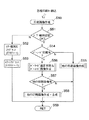
次に、テープ印刷装置1の制御全体の処理フローについて、図5を参照して説明する。電源キー320を押すこと(電源オン)により処理が開始すると、同図に示すように、まず、テープ印刷装置1を、前回の電源オフ時の状態に戻すために、退避していた各制御フラグを復旧するなどの初期設定を行い(S1)、次に、前回の表示画面を初期画面として表示する(S2)。
【0084】
図5のその後の処理、すなわちキー入力か否かの判断分岐(S3)および各種割込処理(S4)は、概念的に示した処理である。実際には、テープ印刷装置1では、初期画面表示(S2)が終了すると、キー入力割込を許可し、キー入力割込が発生するまでは、そのままの状態を維持し(S3:No)、何らかのキー入力割込が発生すると(S3:Yes)、それぞれの割込処理に移行して(S4)、その割込処理が終了すると、再度、その状態を維持する(S3:No)。
【0085】
上述のように、テープ印刷装置1では、主な処理を割込処理により行うので、印刷画像の印刷準備ができていれば、ユーザが任意の時点で印刷キー321を押すことにより、印刷処理割込が発生して、印刷処理が起動され、印刷画像の印刷ができる。
【0086】
図6は、テープ印刷装置1における典型的な画像作成・印刷処理を示すフローチャートである。この処理(S10)では、同図に示すように、各種入力・選択・設定・指示を行う(S20)。より具体的には、ここでは、図7に示すように、文字入力編集(S21)の他にも、各種の入力・選択・設定・指示ができ、ユーザはこれらのオプションの中から任意に入力・選択・設定・指示をすることができる。
【0087】
例えば一般的な任意のキャラクタ(以下「文字」で代表する)を並べたキャラクタ列(文字列)の印刷画像を印刷する場合、ディスプレイ4により確認しながら、キーボード3により、まず、任意の文字列、例えば1行目に「ABCDEF」、2行目に「GHIJKL」などのように文字を入力し(S21)、次に、文字等のサイズや装飾を指定し(図示せず)、色指定等を行う(図示せず)。この場合、サイズや装飾はフォームキー322により選択画面を表示させて、カーソルキー330により選択肢を反転表示させ、選択キー323により確定することにより選択して指定する。また、色指定は、ディスプレイ4の表示画面41上で、C(シアン)、M(マゼンタ)、Y(イエロー)の階調値を、所定の色変換テーブルに規定された色情報に基づいて色指定キー324により指定し、文字やその背景を色設定キー325により指示して設定する。
【0088】
また、図6に示すように、各種入力・選択・設定・指示(S20)と並行(相前後)して、後述のテープ種別設定(S30)が行われる。このテープ種別も、図2で前述のテープ識別センサ141による自動検出の他、図7に示すように、、ユーザが任意に手動入力(マニュアル入力)が可能であり(S25)、フォームキー322により表示される選択画面で「テープ種別設定」の選択肢を反転表示させ、選択キー323により確定することにより選択して指定する。この「テープ種別設定」を選択すると、その下位階層として、テープ幅による選択肢からの選択や数値の直接入力によりテープTのテープ幅を設定したり、テープTの材質をその選択肢から選択したりするための選択画面に遷移するので、ユーザは、カーソルキー330により選択肢を反転表示させ、選択キー323により選択したり、あるいは数字キー群313を使用して数値入力することにより、テープTの種別を指定できる。
【0089】
すなわち、図8に示すように、テープ種別のマニュアル入力(図7のS25:以下単に「テープ種別入力」)またはテープ交換(テープカートリッジ5の交換)によりテープ種別設定割込が発生して、テープ種別設定(S30)が起動されると、まず、上記のテープ種別入力(S25)によるマニュアル設定がされたか否かを判別する(S31)。ここで、マニュアル設定がされていないとき(S31:No)には、テープ識別センサ141による自動検出の結果(テープ識別信号)に基づくテープ種別を取得して設定し(S33)、マニュアル設定がされているとき(S31:Yes)には、そのマニュアル入力されたテープ種別を設定して(S32)、処理(S30)を終了する(S34)。
【0090】
ただし、テープ種別入力(S25)をした場合、下記の印刷指示(S26)までにテープカートリッジ5の交換等をすることにより、テープ識別センサ141により自動検出された実際に装着されているテープTの種別とマニュアル入力した種別とを合わせておく必要があり、印刷指示(S26)後まで双方が一致しない場合、次の印刷画像作成(S50)では、テープTに合わない画像を印刷しても意味がないので、単にエラーを検出して終了し(図10のS51〜S53、S59参照)、エラーなので(図6のS60:Yes)、その旨を報知して(S80)、再度、新たな各種入力・選択・設定・指示(S20)やテープ種別設定(S30)を待つ状態(S40:No)に戻る。
【0091】
また、ユーザは、図7に示すように、任意の時点で種々の印刷指示のうちのいずれかを指示(S26)することができ、図6に示すように、何らかの印刷指示があるまで(S40:No)、上記の各種入力・選択・設定・指示(S20)やテープ種別設定(S30)を待つ状態を維持する(S20〜S40)。この状態で、何らかの印刷指示があると(S40:Yes)、例えば上記の文字列「ABCDEF」等の入力(図6のS20、図7のS21)が終了した後、ユーザが印刷キー321を押すことにより通常印刷が指示(図6のS20、図7のS26)されると(図6のS40:Yes)、印刷画像を表現する印刷画像データを作成する(S50)。なお、一般的な画像は、例えば有効画素を「1」、無効画素を「0」とした2値マトリクス(ドットマトリクス)の画像データなどで表現でき、装置内での実際の処理は画像データに対して行われる。すなわち、例えば印刷画像はそれを表現する印刷画像データに基づいて印刷されたときに印刷画像となるが、以下では、説明を簡略化して、例えば「印刷画像を表現する印刷画像データを作成する」を「印刷画像を作成する」のように説明する。したがって、ここでは、印刷画像を作成する(S50)。
【0092】
そして、印刷画像の作成が終了すると(S50)、エラーが有るか(エラー代表フラグERRF=1か)否かを判別し(S60)、エラーが検出されているとき(S60:Yes)には、詳細なエラーフラグ(後述のエラー報知Aフラグ等)を調べて、その旨(エラー内容等)を報知(ここでは表示画面41にその旨のエラーメッセージを表示)して(S80)、再度、新たな各種入力・選択・設定・指示(S20)やテープ種別設定(S30)を待つ状態(S40:No)に戻る。一方、エラーが無い(エラー代表フラグERRF=0の)とき(S60:No)には、次に、作成された印刷画像を印刷し、定長設定等がされているときにはその印刷画像の前後端でのカット処理により所望のラベルを作成し(S70)、画像作成・印刷処理(S10)を終了する(S90)。
【0093】
テープ印刷装置1では、上記の文字列「ABCDEF」の文字列画像等ばかりでなく、バーコード画像を印刷画像とすることができる。そこで、以下、印刷画像としてバーコード画像を作成・印刷する場合について説明する。この場合、図6で上述の各種入力・選択・設定・指示(S20)では、図7で上述の文字入力編集(S21)等ではなく、同図のバーコード線色設定(第1バー色設定:S22)、バーコード背景色設定(第2バー色設定:S23)、バーコード配置設定(S24)等を行う(S20)。
【0094】
この場合、ユーザは、バーコード設定キー341を押すことにより、ディスプレイ4の表示画面41上に、「バーコード設定」の選択画面を表示させて、カーソルキー330により「線色」、「背景色」、「配置」等の選択肢を反転表示させ、選択キー323により任意の1つを選択できる。なお、バーコード設定キー341により「バーコード設定」の選択画面を表示して選択する代わりに、例えばバーコード線色設定キー、バーコード背景色設定キー、バーコード配置設定キー等を個別に設けて、キー入力により各処理(図7のS22〜S24)を直接起動して、下記のそれぞれの設定画面や選択画面を直接表示させて遷移するようにしても良い。
【0095】
上記の「バーコード設定」の選択画面で、例えばユーザにより「線色」が選択されると、テープ印刷装置1では、バーコード線色設定(S22)の処理に移行して、下位階層の選択画面である「バーコード線色」の選択画面に画面遷移する。この選択画面では、線色(第1バー色)の候補となる各色の選択肢を表示するので、ユーザは、カーソルキー330により任意の選択肢を反転表示させ、選択キー323により選択できる。また、同様に、例えばユーザにより「背景色」が選択されると、バーコード背景色設定(S23)の処理に移行して、下位階層の選択画面である「バーコード背景色」の選択画面に画面遷移し、背景色(第2バー色)の候補となる各色の選択肢を表示するので、ユーザは、カーソルキー330により任意の選択肢を反転表示させ、選択キー323により選択できる。
【0096】
また、上記の「バーコード設定」の選択画面で、例えばユーザにより「配置」が選択されると、テープ印刷装置1では、バーコード配置設定(S24)の処理に移行して、下位階層の選択画面である「バーコード配置」の選択画面に画面遷移する。この選択画面では、例えば「種類」、「数値情報」、「印刷位置」等の選択肢を表示するので、ユーザは、カーソルキー330により任意の選択肢を反転表示させ、選択キー323により、図9に示す各種設定処理(S241〜S243)を選択できる。
【0097】
ここで、例えばユーザにより「種類」が選択されると、バーコード種類選択(S241)の処理に移行して、下位階層の選択画面である「バーコード種類」の選択画面に画面遷移する。この選択画面では、テープ印刷装置1で処理可能なバーコード種類の選択肢を表示するので、ユーザは、カーソルキー330により任意の選択肢を反転表示させ、選択キー323により選択できる。また、例えばユーザにより「数値情報」が選択されると、バーコード数値情報入力(S242)の処理に移行して、数値情報の入力画面に画面遷移する。この入力画面では、ユーザは、前述の文字入力編集(図7のS21)と同様に、文字キー群31によりバーコードで表現する文字(英字、数字、記号等を含む)を入力でき、入力後に選択キー323を押すことにより確定できる。ここで、テキストデータとして入力されたこれらの文字の情報は、それらを表現する所定の2値(ここでは0および1)の情報(2値情報)としてバーコード(画像)に反映される。
【0098】
テープ印刷装置1では、上記の「バーコード種類」の選択画面において、例えば「JAN−8」、「JAN−13」、「ITF」(INTERLEAVED 2 of 5)、「NW−7」(CODABAR)、「CODE39」、「UPC−A」、「UPC−E」、「CODE 2 OF 5」、「CODE11」、「CODE93」、「CODE128」等の選択肢を表示するので、ユーザは、カーソルキー330により、任意の選択肢を反転表示させ、選択キー323により選択できる。
【0099】
例えば図18に例示されたバーコードの種類のうち、「JAN」(「JAN−8」、「JAN−13」)や「UPC」(「UPC−A」、「UPC−E」)では、図19に示すように、数値情報(10進数:コード)を2進数で表現し、一定の幅の黒バーを「1」、白バーを「0」として、数値情報に対応するバーコードを配置する。また、「ITF」では、図20に示すように、数値情報(コード)を2進数で表現し、太いバー(太バー)を「1」、細いバー(細バー)を「0」とし、この場合は、奇数番目の数値を黒バー(黒の太バーと細バー)として、偶数番目の数値を白バー(白の太バーと細バー)として交互に入れ組むことにより、数値情報に対応するバーコードを配置する。
【0100】
また、「NW−7」では、図21に示すように、数値情報(キャラクタ:コード)を2進数で表現し、黒バーと白バーを交互に用いながら、太バーを「1」、細バーを「0」として、それに対応するバーコードを配置する。「CODE39」でも、基本的には「NW−7」と同様に、図22および図23に示すように、数値情報(キャラクタ:コード)を2進数で表現し、黒バーと白バーを交互に用いながら、太バーを「1」、細バーを「0」として、数値情報に対応するバーコードを配置する。すなわち、バーコードの各種類について、例えば図24〜図30の各図(a)に示すように、バーコードの配置が規定されているので、例えば各図(b)に示すような「数値情報」を入力すると、各図(c)に示すバーコード画像のバーコード配置となる。
【0101】
ここで、後述の「印刷位置」が単にそのときに用意された文字列の後ろ(「右全体」)に設定されている場合には、例えば図31〜図34に示すように、準備ができている各文字列(ここでは規格の名称の文字列を例示する)の画像の後ろに、バーコード画像が印刷され、カット処理により所望のラベルQ1〜Q16を作成できる。なお、この例では、図31〜図34に印刷されたバーコード画像B1〜B16は、図24〜図30に示したバーコード画像B1〜B16と同じ画像であり、また、これらの画像の数値の最後にはチェックディジット(CD)が含まれている。また、テープ印刷装置1では、「バーコード種類」の下位階層の選択画面(任意のバーコード種類を選択した後に画面遷移する遷移先の選択画面)において、バーコード(画像)の幅(各バーの長さ)方向のサイズを例えば「小さめ」、「普通」、「大きめ」などの選択肢から選択でき、細バーと太バーを用いる種類ではその太さの比率「細/太」を例えば「2.2」〜「3.0」の間の複数の選択肢から選択できる。また、「UPC」や「JAN」ではチェックディジット(CD)が自動付加されるが、その他の種類では、「CD」の有無を選択できる。
【0102】
上述のように、テープ印刷装置1では、バーコードにおける2種のバーの配置方法が相互に異なる複数種類のバーコードの種類が規定されており、複数種類のバーコードの種類から任意の1種を選択するので、バーコードの種類を選択するだけで容易にバーコードの配置方法を設定でき、そのバーコードの配置方法に従って2種のバーの配置を容易に設定できる。また、バーコードは、2種のバーのそれぞれを所定の2値のうちの一方および他方としたときの数値情報を表現しており、その数値情報を入力するので、数値情報入力によりバーコード配置を容易に設定できる。また、この場合、所定の2値は、0および1であるので、数値情報は、2進数で表現される数値情報であり、任意の数値情報の入力により、その数値情報を2進数で表現したときの0に対応する位置には、2種のバーのうちの一方を配置し、1に対応する位置には、他方を配置することができ、それらによりバーコード配置を容易に設定できる。
【0103】
一方、図9で前述の「バーコード配置」の選択画面で、例えばユーザにより「印刷位置」が選択されると、バーコード印刷位置設定(S243)の処理に移行して、下位階層の選択画面である「バーコード印刷位置」の選択画面に画面遷移する。この選択画面では、ラベルとして作成される場合のバーコード画像のラベル上の印刷位置の選択肢、例えば「右全体」、「右上」、「右中央」、「右下」、「中央全体」、「中央上」、「中心」、「中央下」、「左全体」、「左上」、「左中央」、「左下」、「全体」、「任意」などの選択肢を表示するので、ユーザは、カーソルキー330により任意の選択肢を反転表示させ、選択キー323により選択できる。
【0104】
ここで、「右上」、「右中央」、「右下」、「中央上」、「中心」、「中央下」、「左上」、「左中央」、「左下」の選択肢は、基本的な考え方としては図35の印刷領域(印刷位置)を示し、例えば図36のそれぞれの印刷位置を示す。また、「右全体」、「中央全体」、「左全体」の選択肢は、基本的な考え方としては図37の印刷位置を示し、例えば図38のそれぞれの印刷位置を示すが、テープTの長手方向に複数の段落(ブロック)が設定されている場合には、「右全体」は、前述の図31〜図34や図45で後述のラベルR8のように全体として最後の段落(ブロック)であることを示し、「左全体」は、図39に示すように、最初の段落(以下「第1段落」)BLK1であることを示す。また、「中央全体」は、例えば2段落構成の第2段落BLK2(この場合「右全体」と同じ)、3段落構成の第2段落BLK2(すなわち中央の段落)、4段落構成の第2段落BLK2、5段落構成の第3段落BLK3、6段落構成の第3段落BLK3、などを示す。また、「全体」の選択肢は、文字通り、ラベルの領域全体を示す。
【0105】
そして、テープ印刷装置1には、印刷位置の指定としては特殊な「任意」の選択肢がある。ユーザがこの選択肢を選択すると、「バーコード印刷位置」の選択画面から図7で前述の文字入力編集(S21)の画面(以下「テキスト編集画面」)に画面遷移するとともに、そのときのカーソルKの位置にバーコードマークを表示する。すなわち、「任意」の選択肢がユーザにより選択されると、このバーコードマークを利用した「印刷位置」の指定ができるようになるので、以下に説明する。
【0106】
ここで、通常の文字列画像を印刷したラベルを作成する場合、例えば図40(a)に示すラベルR10を作成する場合、ディスプレイ4の表示画面41上には、同図(b)に示すようにテキストデータ(に対応する表示画像)が表示されるので、ユーザはこの表示画面41に表示されたテキスト編集画面上で文字列画像の入力・編集ができる。この場合、広告を示す図形(広告マーク)M10や人間を示す図形(人間マーク)M11も普通の1文字として扱われる。この例の場合、第1段落BLK1に印刷される画像の元になるテキストデータとしては、広告マークM10のみの1行のみが入力されている。また、第2段落BLK2の1行目には「広告プラン」、2行目には「〜春のキャンペーン向け〜」が入力され、第3段落の1行目には「営業部企画課」、2行目には「宣伝担当」、3行目には、人間マークM11に続いて「山岡」が入力されている。
【0107】
また、例えば図41(a)に示すラベルR20を作成する場合、同図(b)に示すように、ユーザにより、第1段落BLK1の1行目に電話マークM21に続いて「内線」が入力され、選択キー323の押下により改行され、2行目として「営業部」が入力され、カーソルKが「営業部」の後ろの位置、すなわち図示のカーソル位置K1にある状態で、ユーザにより改段落キー(ここでは改段落キーはシフトキー327とともに選択キー323を押すものとする)が押されると、カーソル位置K2の位置にカーソルKを表示することにより、改段落による次の段落(第2段落BLK2)の1行目の入力を促す。これに応じて、ユーザにより、第2段落BLK2の1行目として「営業1課131」、(改行後)2行目として「営業2課132」、(改行後)3行目として「営業3課133」が入力され、再度、改段落キーが押されると、カーソルKを表示することにより、改段落による次の段落(第3段落BLK3)の1行目の入力を促す。この状態で、ユーザにより印刷キー321が押されると、同図(a)のように印刷し、そのラベルR20を作成できる。
【0108】
また、上記の状態からユーザによりカーソルキー330が操作され、図42(b)に示すように、カーソルKが電話マークM21の後ろの位置、すなわち図示のカーソル位置K1にある状態で、ユーザにより改段落キーが押されると、カーソル位置K2の位置にカーソルKを表示するとともに、そのカーソル位置K2以降、すなわち「内線」以降を第2段落BLK2の内容とし、「営業1課131」以降、すなわち元の第2段落BLK2の内容を第3段落BLK3の内容として移行し、電話マークM21のみから成る第1段落BLK1を新たに作成する。この状態で、ユーザにより印刷キー321が押されると、同図(a)のように印刷し、そのラベルR21を作成できる。
【0109】
また、通常の文字列画像の場合、周知のように種々の割付処理ができる。すなわち種々の割付処理を指定することにより、例えば図43に示すように、任意長印刷によるラベルR30の他、定長設定を行って「前寄せ」(「前揃え」、「左端揃え」、「行頭揃え」ともいう)を指定されて印刷されたラベルR31、「中寄せ」(「中揃え」、「中央揃え」、「センタリング」ともいう)を指定されて印刷されたラベルR32、「均等割付」(「文字間揃え」、「文字間均等」ともいう)を指定されて印刷されたラベルR33、「後寄せ」(「後揃え」、「右端揃え」、「行末揃え」ともいう)を指定されて印刷されたラベルR34、などの種々の割付処理を施したラベルを作成できる。
【0110】
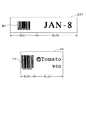
印刷位置設定の「任意」の選択肢がユーザにより選択された場合に表示されるバーコードマーク(以下では仮に「※」で示す)は、表示画面41上では、図40〜図42で上述の広告マークM10、人間マークM11、電話マークM21等と同様に扱われる。すなわち、同様に1文字として扱われる。また、1文字として扱われるので、図43で上述したのと同様の種々の割付処理を施したラベルも作成できる。例えば図44(a)に示すように、第1段落BLK1に文字列「JAN−8」、第2段落BLK2にバーコードマークM0である「※」が入力され表示(以下「入力表示」)された状態で、ユーザにより印刷キー321が押されると、バーコードマークM0の示す印刷位置に、すなわち第2段落BLK2に、例えばバーコード画像B1を画像展開して、前述した図31のように印刷し、そのラベルQ1を作成できる。図31〜図34で前述の各ラベルQ2〜Q16も同様にして作成できる。
【0111】
また、逆の順で、例えば図44(b)に示すように、第1段落BLK1にバーコードマークM0(「※」)、第2段落BLK2に文字列「JAN−8」が入力表示された状態で、ユーザにより印刷キー321が押されると、バーコードマークM0の示す印刷位置に、すなわち第1段落BLK1に、例えばバーコード画像B1を画像展開して、前述した図39(a)のように印刷し、そのラベルQ17を作成できる。また、例えば図44(c)に示すように、第1段落BLK1に同様のバーコードマークM0(「※」)、第2段落BLK2の1行目にトマトを示す図形(トマトマーク)M1に続いて文字列「Tomato」、2行目に「¥50」が入力表示され、例えば「後寄せ」が指定された状態で、ユーザにより印刷キー321が押されると、バーコードマークM0の示す印刷位置、すなわち第1段落BLK1に、例えばバーコード画像C9を画像展開し、かつ、第2段落BLK2は「後寄せ」に割り付けて、前述の図39(b)のように印刷し、そのラベルR9を作成できる。
【0112】
同様に、例えば図44(d)に示すように、第1段落BLK1の1行目にバーコードマークM0(「※」)、2行目にトマトを示す図形(トマトマーク)M1に続いて文字列「Tomato」、3行目に「¥50」が入力表示され、例えば「中寄せ」が指定された状態で、ユーザにより印刷キー321が押されると、バーコードマークM0の示す印刷位置、すなわち第1段落BLK1の1行目に、例えばバーコード画像C1を画像展開し、かつ、「中寄せ」に割り付けて、図45のラベルR1を作成できる。また、同様に入力表示され、例えば「前寄せ」が指定されていると、ユーザの印刷指示により、バーコードマークM0の示す第1段落BLK1の1行目に、かつ、「前寄せ」に割り付けて例えばバーコード画像C3を画像展開し、図45のラベルR3を作成できる。また、同様に入力表示され、例えば「後寄せ」が指定されていると、印刷指示により、第1段落BLK1の1行目に、かつ、「後寄せ」に割り付けて例えばバーコード画像C5を画像展開し、図45のラベルR5を作成できる。
【0113】
同様に、例えば図44(e)に示すように、第1段落BLK1の1行目にトマトマークM1に続いて文字列「Tomato」、2行目にバーコードマークM0(「※」)、3行目に「¥50」が表示され、例えば「中寄せ」が指定されていると、印刷指示により、バーコードマークM0の示す第1段落BLK1の2行目に、かつ、「中寄せ」に割り付けてバーコード画像C2を画像展開し、図45のラベルR2を作成できる。また、同様に入力表示され、例えば「前寄せ」が指定されていると、バーコードマークM0の示す第1段落BLK1の2行目に、かつ、「前寄せ」に割り付けてバーコード画像C4を画像展開し、図45のラベルR4を作成できる。また、同様に入力表示され、例えば「後寄せ」が指定されていると、印刷指示により、第1段落BLK1の2行目に、かつ、「後寄せ」に割り付けてバーコード画像C6を画像展開し、図45のラベルR6を作成できる。
【0114】
また、例えば図44(f)に示すように、ユーザが同図(d)の状態から2行目および3行目の前の部分にスペースを挿入してから印刷を指示すると、例えば「前寄せ」が指定されていても、スペース分だけ後ろ(右)側によったバーコード画像C7を画像展開し、図45のラベルR7を作成できる。同様に、例えば図44(g)に示すように、第1段落BLK1の1行目にトマトマークM1に続いて文字列「Tomato」、2行目に「¥50」が表示され、第2段落BLK2にバーコードマークM0(「※」)が入力表示され、例えば「後寄せ」が指定されていると、印刷指示により、バーコードマークM0の示す第2段落BLK2にバーコード画像C8を画像展開し、図45のラベルR8を作成できる。
【0115】
なお、この「任意」の(選択肢による)「印刷位置」の指定では、バーコードマークM0(「※」)を、通常の記号(例えば上述の広告マークM10、人間マークM11、電話マークM21等)と同様に1文字として扱うので、その前後にスペースを任意に挿入して印刷位置を微妙に変更したり、文字サイズの変更により(主に文字高方向の)サイズを変更したりすることもできる。すなわち、この「任意」の「印刷位置」の指定では、自由度の高い印刷位置の指定ができる。なお、上記の例では、説明の便宜上(説明文の中に入れやすいように)、バーコードマークM0を「※」(図46(a)参照)としたが、上述の広告マークM10、人間マークM11、電話マークM21等と同様に、よりバーコードのイメージにあった図形(例えば同図(b)参照)とした方が、印刷のイメージを把握し易いので好ましい。
【0116】
図6に示すように、上述のようなバーコード画像の準備が終了した状態(S20〜S30、S40:No)で、ユーザによりバーコード印刷キー342が押されると、例えば印刷キー321が押された場合と同様に、各種印刷キー割込(ここではバーコード印刷キー割込)が発生して(図6のS40:Yes、図7のS26参照)、印刷画像作成(S50)の処理を起動する。なお、本実施形態では、バーコード画像の印刷用にバーコード印刷キー322を個別に設けたが、他の指示方法、例えば各種印刷の一種としてバーコード印刷を指定する文字(数字等)のキーと印刷キー321とを同時に押すことにより、各種印刷の一種としてバーコード印刷を指示するようにすることもできる。
【0117】
印刷画像作成(S50)の処理が起動されると、図10に示すように、まず、テープ種別設定がOKか否かを判別する(S51)。例えば、前述のテープ種別入力(図7のS25)によるテープ種別とテープ識別センサ141の検出結果が合わない場合など、設定されたテープTの種別が異常(NG)と判別したとき(S51:No)には、その旨の詳細なエラー報知Eフラグをセットし(ERE←1:S52)、エラー代表フラグERRFをセットして(ERRF←1:S53)、処理(S50)を終了する(S59)。また、テープ種別設定OKと判別したとき(S51:Yes)には、次に、バーコード印刷有りか否か、すなわち各種印刷の一種としてバーコード印刷が指示されたか否かを判別し(S54)、バーコード印刷が無いとき(S54:No)には、前述の文字列「ABCDEF」の文字列画像その他の印刷画像を作成して(S55)、処理(S50)を終了する(S59)。他の印刷画像作成(S55)については従来と同様なので、詳細な説明は省略する。
【0118】
一方、バーコード印刷有りと判別したとき(S54:Yes)には、次に、設定されたバーコードが読取規格に適合しているか否か(バーコード適否)を判別するとともに、適合している場合には、そのバーコード画像(実際にはそれを表現するバーコード画像データ)を作成し(バーコード適否判別&バーコード画像作成:S56)、続いて、他の印刷画像が有るか否かを判別する(S57)。前述のように、バーコード画像以外の画像(例えば文字列の画像)の準備ができてからバーコード印刷が指示されたとき(S57:Yes)には、その画像(を表現する画像データ)を作成し、バーコード画像と合成してから(S58)、処理(S50)を終了し(S59)、バーコード画像以外の画像が無いとき(S57:No)には、そのまま、処理(S50)を終了する(S59)。
【0119】
図6で前述のように、印刷画像作成(S50)が終了すると、エラー有か否かを判別し(S60)、エラー有りのとき(S60:Yes)には、詳細なエラーフラグを調べて、その旨を報知して(S80)、再度、新たな各種入力・選択・設定・指示(S20)やテープ種別設定(S30)を待つ状態(S40:No)に戻る一方、エラー無しのとき(S60:No)には、次に、作成された印刷画像を印刷し、定長設定等のときには前後端でのカット処理により所望のラベルを作成し(S70)、画像作成・印刷処理(S10)を終了する(S90)。
【0120】
なお、前述のように、テープ印刷装置1では、印刷画像をインクジェット方式でカラー印刷するが、この場合、カラーの基本色としてC(シアン)、M(マゼンタ)、Y(イエロー)、K(ブラック)のインクを使用して印刷するため、印刷画像を表現する印刷画像データとしてもCMYKの4基本色に対応して作成し、基本色別配置バッファに配置された各基本色に対応する画像データに基づいてかつ対応するインクを用いて、印刷画像を各基本色に分解して印刷する。このため、上述の印刷画像作成(S50)で印刷画像としてバーコード画像を作成(図11のS571参照)した場合も、各基本色に分解して印刷する。
【0121】
すなわち、このテープ印刷装置1では、バーコード画像は、インクジェット方式で、カラーの複数の基本色(ここでは4色)に分解して印刷され、基本色にはカラー3原色が含まれ、このカラー3原色としては、C(シアン)、M(マゼンタ)およびY(イエロー)の組合せ(以下「CMY」)が使用される。この場合、いわゆる減法混色により種々の色(カラー)を表現できるので、種々の色のバーコード画像を印刷でき、一般的な各種のXYプロッタやプリンタ等における印刷などと同様に、反射光によってカラー表現する場合に適したカラー画像のバーコード画像を印刷できる。また、基本色にはカラー3原色のCMYの混合色に相当する基本色がさらに含まれる。すなわち、CMYの混合色はK(ブラック)となるが、一般に、実際に混色したK(ブラック)より、K(ブラック)のインクを用意して単独で印刷した方がきれいなブラックを得られるため、このK色を含めることにより、4(基本)色によるきれいなカラー画像としてバーコード画像(印刷画像)を印刷できる。
【0122】
また、前述のように、テープ印刷装置1では、印刷画像として前述の「ABCDEF」等の文字列画像を印刷する場合、色指定キー324や色設定キー325により文字やその背景の印刷色を指定できる。このため、印刷対象物であるテープTの地色が白色の場合、背景の印刷色(背景色)によりテープTの地色を演出できる。この場合、この背景色によりテープTの地色を演出しておいて、バーコード線色(第1バー色)またはバーコード背景色(第2バー色)としてその地色(背景色)と同色を設定したバーコード画像を印刷すれば、同色に設定した側のバーは背景と同化する。すなわち、バーコード線色(第1バー色)およびバーコード背景色(第2バー色)の一方を地色(背景色)として、バーコード画像の背景を印刷することにより、そのバーが背景と同化するため、他方をバー色として、背景上にそのバー色でバーを描いたバーコード画像が得られる。
【0123】
テープ印刷装置1では、前述のように、印刷対象物であるテープTは、バーコード画像を印刷後にその印刷部分をラベルとして貼付可能なものである。すなわち、上記の場合、ラベルとして貼ったときに商品の色に対して目立つ背景色を設定してバーコードの部分を目立たせたり、逆に商品の色に対して目立ち難い背景色にしてバーコードの部分を目立たなくするなど、さらに所望の色彩のバーコード画像が得られる。なお、上記の説明では、背景色によりテープTの地色を演出した場合としたが、地色として演出しなくても、バーコード線色(第1バー色)またはバーコード背景色(第2バー色)として元々のテープTの地色と同色を設定すれば同様となる。また、ラベル上の印刷位置を「全体」としてラベル全体に(周辺に空白を残さずに)バーコード画像を印刷しても同様の効果が得られる。
【0124】
次に、上記のバーコード適否判別&バーコード画像作成(S56)について、詳述する。図11に示すように、本処理(S56)が起動されると、まず、バーコード配置設定が済んでいるか否か、すなわち図6の各種入力・選択・設定・指示(S20)において、図7のバーコード配置設定(S24:詳細は図9)が済んでいるか否かを判別し(S561)、済んでいないとき(S561:No)には、その旨の詳細なエラー報知Aフラグをセットし(ERA←1:S562)、エラー代表フラグERRFをセットして(ERRF←1:S578)、処理(S56)を終了する(S579)。また、バーコード配置設定(図7のS24)が済んでいるとき(S561:Yes)には、次に、図7で前述のバーコード線色設定(S22)がされているか否か、すなわちバーコード線色設定が有るか否かを判別する(S563)。ここで、バーコード線色設定が無いとき(S563:No)には、次に、図7で前述のバーコード背景色設定(S23)がされているか否か、すなわちバーコード背景色設定が有るか否かを判別する(S564)。
【0125】
ここで、バーコード背景色設定が無いとき(S564:No)には、バーコードについて線色も背景色も設定されていないことになり、バーコード画像の作成(図11のS571)もその印刷(図6のS70)もできないので、その旨の詳細なエラー報知Bフラグをセットし(ERB←1:S565)、エラー代表フラグERRFをセットして(ERRF←1:S578)、処理(S56)を終了する(S579)。なお、ここでは、両バー色の設定が無い場合にはエラー報知とするが、エラーとして扱わず、デフォルトの色(例えば線色を黒、背景色を白とするなど)として、バーコード画像として作成・印刷することも可能である。
【0126】
ところで、前述のように、従来から、反射率が高い方のバー(ここではバーコード両端の余白(マージン)を含む)を、白バーまたはスペース等とも呼び、これらのバー色としては、例えば白、黄色、赤、ピンク、オレンジなどの、白系、赤系または薄い色が使用される。一方、反射率が低い方のバーを、黒バーまたは単にバーとも呼び、これらのバー色としては、例えば黒、緑、青、紺、焦げ茶などの濃い色、または、レーザー(赤)の補色となる色が使用される。
【0127】
テープ印刷装置1では、バーコードの線色(第1バー色)および背景色(第2バー色)を設定できるが、文字通り、線色(第1バー色)を黒バーの色、背景色(第2バー色)を白バーの色としても良いし、逆に線色(第1バー色)を白バーの色、背景色(第2バー色)を黒バーの色としても良い。もちろん、例えば上述の前者(線色(第1バー色)=黒バー色、背景色(第2バー色)=白バー色)または後者(前者の逆)のように固定的な設定とすることもできるが、テープ印刷装置1の場合、設定(操作)上、便宜的に「バーコード線色」と「バーコード背景色」に区別しているだけなので、各々に設定された色のうちの反射率が高い方の色のバーを白バー、反射率が低い方の色のバーを黒バーとして、バーコード画像作成(図11のS571)を行う。
【0128】
そこで、以下では、説明を簡略化して理解を容易にするため、一般的に(従来から)白バーの色として使用されるか黒バーの色として使用されるかに拘わらず、テープ印刷装置1で印刷可能な色(カラー)の例として、すなわち、バー色として印刷可能な色(カラー)の例として、例えばa色、b色、c色、地色が選択できるものとして説明する。このため、例えば前述の「バーコード線色」の選択画面では、線色(第1バー色)の候補となる各色の選択肢として、a色、b色、c色、地色の選択肢を表示する。ここで、地色とは印刷対象物であるテープTの地色(印刷しないときの用紙面の色)である。すなわち、「バーコード線色」の選択画面では、線色(第1バー色)の候補となるa色、b色、c色、地色の選択肢を表示するものとし、ユーザは、カーソルキー330により、そのうちの任意の選択肢を反転表示させ、選択キー323により選択できるものとする。また同様に、例えば前述の「バーコード背景色」の選択画面では、背景色(第2バー色)の候補となるa色、b色、c色、地色の選択肢を表示するものとし、ユーザは、カーソルキー330により、そのうちの任意の選択肢を反転表示させ、選択キー323により選択できるものとする。
【0129】
また、前述のように、テープ印刷装置1では、テープTとして、材質の異なるものや、地色が白色以外のものなどが用意されている。一般的に、インクジェット方式による印刷の場合、インクと用紙の表面処理の対応ができれば、紙系、PET(Polyethyleneterephthalate )、金属系、ガラス等の面状のものであれば印刷でき、また、市場では、紙、ビニール、ポリエステル・フィルム、ポリミド・フィルム、布、アルミ箔などがある。そこで、以下では、上述のバー色と同様に、説明を簡略化して理解を容易にするため、テープT(すなわち印刷対象物となる用紙)の材質の例として、A、B、Cの材質が選択できるものとする。すなわち、装着するテープTとして、A、B、Cの材質のテープTを装着できるものとして説明する。
【0130】
また、前述のように、テープ印刷装置1では、種々のバーコード種類のうちの任意の1つを選択できるが、これらの白バーと黒バーとの反射率に関する条件としては、一般的に、例えば図12に示すように、ANSI(全米規格協会)やJIS等により、読み取りのために許容されるPCS(Print Contrast Signal )の値(PCS値)、反射率比の値、または、MRD(Minimum Reflectance Difference)の値(MRD値)、などが規格化されている(以下これらを「読取規格」という)。そこで、以下では、主に図12のNo.1のPCS値による読取規格を例に挙げて説明する。
【0131】
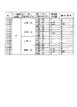
この場合、テープ印刷装置1では、2種のバー(すなわち白バーおよび黒バー)の反射率に関する条件を規定した所定のバーコードの読取規格として、例えば図13〜図15に示すように、テープTの種別(特に材質)に応じたバーコード読取規格値テーブルがROM220に記憶されている。各図の右端の「適(○)/否(×)」の欄において、「×」は、白バーおよび黒バーの色の組合せが読取規格(ここではPCS値の条件:PCS≧0.75)に不適合であることを示し、「○」は、読取規格に適合することを示し、「○○」は、「○」よりさらに良い組合せであることを示している。また、ROM220には、その読取規格に適合するように、例えば図16に示すように、バー色自動設定テーブル等が予め規定され記憶されている。また、その読取規格に適合するか否かの判別のために、例えば図17に示すように、バー色適否判別テーブルが予め規定され記憶されている。
【0132】
なお、ここでは、この図17には、テープTが種別(材質)Aの場合のみ示して省略したが、もちろん、バー色適否判別テーブルには、テープTが種別(材質)BやCの場合においての値も含まれている。また、この場合、例えば図17のNo.3−2〜3−4、3−7、3−14〜3−15に示すように、第1バー色の反射率の方が第2バー色の反射率より高い場合と、No.3−5、3−8〜3−10、3−12、3−13に示すように、第1バー色の反射率の方が第2バー色の反射率より低い場合とが混在しているが、これは、前述のように、テープ印刷装置1では、バーコード線色(第1バー色)とバーコード背景色(第2バー色)とを同等に扱っているためであって、前述のように、これらを固定的に、例えばバーコード線色(第1バー色)=黒バー色、バーコード背景色(第2バー色)=白バー色として固定的に扱えば、No.3−5、3−8〜3−10、3−12および3−13のみとなるし、その逆となるように扱えば、No.3−2〜3−4、3−7、3−14〜3−15のみとなって、バーコード線色(第1バー色)=バーコード背景色(第2バー色)も含めると、図13と同じになるので、図13〜図15に示すバーコード読取規格値テーブルで代用しても良い。
【0133】
また、図16のバー色自動設定テーブルおよび図17のバー色自動設定テーブルの右端の「対応No.」の欄は、図13〜図15のバーコード読取規格値テーブルの対応するNo.を示す。すなわち、図16のバー色自動設定テーブルも図17のバー色適否判別テーブルも、図13〜図15のバーコード読取規格値テーブルに基づくものなので、このバー色適否判別テーブルのみ記憶しておいて、適宜、バー色自動設定テーブルやバー色適否判別テーブルの代用として利用することもできる。ただし、以下の説明では理解しやすいように、これらのテーブル(バーコード読取規格値テーブル、バー色自動設定テーブル、バー色適否判別テーブル)は、ROM220内に個別に記憶されているものとする。
【0134】
そして、上述の場合、これらのテーブル(バーコード読取規格値テーブル、バー色自動設定テーブル、バー色適否判別テーブル)は、テープ(印刷対象物)Tの種別に対応して規定されている(図13〜図17参照)。すなわち、テープ印刷装置1では、バーコードの読取規格に基づく規定値やそれによる適否等は、テープ(印刷対象物)Tの種別(特に材質)に対応して規定されており、そのテープTの種別を検出または設定するので(前述の図6のS30、図8参照)、ユーザは、その種別を意識せず、また、バーコードの読取規格を知らなくても(あるいは読取規格に留意しなくても)、以下に説明する処理により、その読取規格に適合する所望の色彩のバーコード画像を容易に印刷できる。
【0135】
例えば、図11に示すように、バーコード背景色設定が有るとき(S564:Yes)には、このバーコード背景色を設定済みバー色として、他方のバーコード線色を自動設定する(S566)。すなわち、上記のバーコード読取規格値テーブルの読取規格に適合するバー色自動設定テーブルを参照することにより、(例えば図16に示すバー色自動設定テーブル等を参照することにより、テープTの材質がAで設定済みバー(背景)色が「a色」のときに他方のバー(線)色を「c色」に設定するなど:No.2−1参照)、他方のバーコード線色を自動設定する(S566)。また、バーコード線色設定が有るとき(S563:Yes)には、同様に、次に、バーコード背景色設定が有るか否かを判別し(S567)、ここで、バーコード背景色設定が無いとき(S567:No)には、バーコード線色を設定済みバー色として、(同様に、例えば図16のバー色自動設定テーブル等を参照して、材質AのテープTで設定済みバー(線)色が「a色」のときに他方のバー(背景)色を「c色」に設定するなど、)他方のバーコード背景色を自動設定する(S568)。
【0136】
上述のように(上記のいずれかの場合)、テープ印刷装置1では、光の反射率が相異なる第1バーおよび第2バーの2種のバーを各1以上配置したバーコードにおける2種のバーの配置を規定したバーコード配置を設定し(図6のS20、図7のS24)、バーコード線色(第1バーの印刷色となる第1バー色)を設定し(図6のS20、図7のS22)、またはバーコード背景色(第2バーの印刷色となる第2バー色)を設定し(図6のS20、図7のS23)、2種のバーの反射率に関する条件を規定した所定のバーコードの読取規格(例えば図12のNo.1のPCS値の条件など)に基づいて、バーコード線色(第1バー色)との組合せが読取規格に適合するように、バーコード背景色(第2バー色)を設定し(図11のS568)、またはバーコード背景色(第2バー色)との組合せが読取規格に適合するように、バーコード線色(第1バー色)を設定する(図11のS566)。
【0137】
これらの自動設定(S566、S568)が終了すると、次に、設定されたバーコード配置、バーコード線色(第1バー色)およびバーコード背景色(第2バー色)に基づいて、バーコード線色(第1バー色)の第1バーおよびバーコード背景色(第2バー色)の第2バーの反射率が高い方を白バーおよび反射率が低い方を黒バーとして、それらを配置したバーコードの印刷画像であるバーコード画像を(前述のように4基本色に分解して)作成し(S571)、処理(S56)を終了する(S579)。
【0138】
バーコード適否判別&バーコード画像作成(S56)が終了すると、図10で前述のように、他の印刷画像が有るとき(S57:Yes)には、その画像を作成し、バーコード画像と合成してしてから(S58)、印刷画像作成(S50)の処理を終了し(S59)、バーコード画像以外の画像が無いとき(S57:No)には、そのまま終了する(S59)。印刷画像作成(S50)が終了すると、図6で前述のように、エラー有りか(エラー代表フラグERRF=1か)否かを判別し(S60)、エラー有りのとき(S60:Yes)には、詳細なエラーフラグ(エラー報知Aフラグ等)を調べて、その旨(エラー内容等)を報知(その旨のエラーメッセージを表示)して(S80)、再度、新たな各種入力・選択・設定・指示(S20)やテープ種別設定(S30)を待つ状態(S40:No)に戻る一方、エラー無し(エラー代表フラグERRF=0)のとき(S60:No)には、次に、作成された印刷画像を印刷し、定長設定等のときにはその印刷画像の前後端でのカット処理により所望のラベルを作成し(S70)、画像作成・印刷処理(S10)を終了する(S90)。
【0139】
すなわち、上述の場合、テープ印刷装置1では、バーコード線色(第1バー色)およびバーコード背景色(第2バー色)の一方を設定すると、その色との組合せが読取規格に適合するように他方の色を設定し、その組合せによるバーコード画像を印刷するので、ユーザは、バーコードの読取規格を知らなくても(あるいは読取規格に留意しなくても)、バーコード線色(第1バー色)およびバーコード背景色(第2バー色)の一方とバーコード配置とを設定するだけで、その読取規格に適合する色彩のバーコード画像を容易に印刷できる。
【0140】
なお、バーコード線色(第1バー色)およびバーコード背景色(第2バー色)の一方を設定した場合に、読取規格に適合するような他方の色に該当する色が無いことが考えられるときには、図示の点線の処理フローとしておき、その他方の色として仮の色(例えば自己と同じ色)を設定して、以下に説明する処理と同様に、次に、読取規格(例えば図12のPCS値の条件など)に適合する(PCS≧0.75)か否かを判別し(S569)、適合しない(S569:No)ことにより、その旨のエラー報知をするようにしても良い。
【0141】
図11に示すように、バーコード線色設定が有り(S563:Yes)、かつ、バーコード背景色設定も有るとき(S567:Yes)には、次に、それらの組合せによる規格値(例えばPCS値)が読取規格に適合する(例えばPCS≧0.75)か否かを判別する(S569)。すなわち、前述のバーコード読取規格値テーブルの読取規格に適合するバー色適否判別テーブルを参照することにより、(例えば図17に示すバー色適否判別テーブル等を参照することにより、例えば材質AのテープTで第1バー(線)色が「c色」で第2バー(背景)色が「地色」のときは適合(No.3−12)、第1バー(線)色が「a色」で第2バー(背景)色が「b色」のときは不適合(No.3−2)と判別するなど、)読取規格に適合する(例えばPCS≧0.75)か否かを判別する(S569)。
【0142】
そして、読取規格に適合しないとき(S569:No)には、その旨の詳細なエラー報知Cフラグをセットし(ERC←1:S570)、エラー代表フラグERRFをセットして(ERRF←1:S578)、処理(S56)を終了する(S579)。一方、読取規格に適合する(反射率差<規格値の)とき(S569:Yes)には、前述と同様に、バーコード画像を作成し(S571)、処理(S56)を終了する(S579)。なお、バーコード適否判別&バーコード画像作成(S56)の終了(S579)〜図10の処理(S57〜S59)〜図6のエラー有りか否かの判別以降(S60〜S90)は、前述と同じなので説明は省略する。
【0143】
上述の場合、テープ印刷装置1では、光の反射率が相異なる第1バーおよび第2バーの2種のバーを各1以上配置したバーコードにおける2種のバーの配置を規定したバーコード配置を設定し(図6のS20、図7のS24)、バーコード線色(第1バーの印刷色となる第1バー色)を設定し(図6のS20、図7のS22)、バーコード背景色(第2バーの印刷色となる第2バー色)を設定し(図6のS20、図7のS23)、バーコード線色(第1バー色)およびバーコード背景色(第2バー色)の色の組合せが、2種のバーの反射率に関する条件を規定した所定のバーコードの読取規格(例えば図12のNO.1のPCS値の条件など)に適合するか否かを判別し(図11のS569)、色の組合せが読取規格に適合すると判別されたときに(図11のS569:Yes)、設定されたバーコード配置、バーコード線色(第1バー色)およびバーコード背景色(第2バー色)に基づいて、バーコード線色(第1バー色)の第1バーおよびバーコード背景色(第2バー色)の第2バーを配置したバーコードの印刷画像であるバーコード画像を作成し(図11のS571〜S579、図10のS57〜S59、図6のS50)、エラー無しのとき(図6のS60:No)には、作成された印刷画像(バーコード画像)を印刷してカット処理により所望のラベルを作成し(S70)、画像作成・印刷処理(S10)を終了する(S90)。
【0144】
すなわち、上記の場合、2種のバーの各色を設定でき、それらの色の組合せがバーコードの読取規格に適合するときに、そのバーコード画像を印刷するので、ユーザは、バーコードの読取規格を知らなくても(あるいは読取規格に留意しなくても)、バーコード配置と2種のバーの色を設定するだけで、その読取規格に適合する所望の色彩のバーコード画像を容易に印刷できる。なお、上記の場合、2種のバーの色の組合せが読取規格に適合しないとき(図11のS570、S578、S579、図10のS57〜S59、図6のS60)には、その旨を報知(図6のS80)するようにしたが、例えば2種のバーのいずれかの色を自動的に調整して印刷したり、色の再設定を促したり、単に印刷せずに処理を終了したり、またはそれらの処理を組み合わせるなど、適切と考えられる処理を任意に規定しておけば良い。これらの場合、いずれにしても、読取規格に適合しないバーコード画像を印刷する手間やそのために生じるテープ(印刷対象物)Tの無駄を防止できる。
【0145】
また、上記の場合、色の組合せが読取規格に適合しないと判別されたとき(同上)に、その旨を報知する(図6のS80)ので、読取規格に適合しない旨をユーザが容易に把握でき、それにより、バー色の設定を変更するなど、迅速な対処ができる。すなわち、従来ならバーコード画像を印刷後にバーコードリーダ等の光学的読取手段により読み取れるか否かを試験(テスト)した時点で、読み取れない色の組合せであることを把握でき、その後に各バー色の設定等からやり直す必要があったが、このテープ印刷装置1では、2種のバーの色を設定した時点で、その組合せが読取規格に適合する否かを判別し、適合しないときにはその旨を報知するので、ユーザは迅速にバー色設定の変更などの対処ができる。
【0146】
なお、上述の実施形態では、インクジェット方式の例を挙げたが、サーマル方式、レーザ方式、ドット・インパクト方式等にも適用できる。また、印刷画像を印刷対象物に印刷するものであれば、ラベルでなくても例えばその印刷対象物をそのままあるいは印刷部分を切り取って商品に貼るなどの方法を採用でき、例えば一般的な印刷装置その他の画像印刷にも適用できる。もちろん、その他、本発明の要旨を逸脱しない範囲で、適宜変更も可能である。
【0147】
【発明の効果】
上述のように、本発明の画像印刷方法およびその装置によれば、バーコードの読取規格に適合する色彩のバーコード画像を容易に印刷できる、などの効果がある。
【図面の簡単な説明】
【図1】本発明の一実施形態に係る画像印刷方法およびその装置を適用したテープ印刷装置1の外観斜視図である。
【図2】図1のテープ印刷装置の制御系のブロック図である。
【図3】図1のテープ印刷装置の装置本体の断面図である。
【図4】図1のテープ印刷装置に装着するテープカートリッジの一例の裁断断面図である。
【図5】図1のテープ印刷装置の制御全体の概念的処理を示すフローチャートである。
【図6】典型的な画像作成・印刷処理の一例を示すフローチャートである。
【図7】図6の各種入力・選択・設定・指示処理の各種オプションの一例を示すフローチャートである。
【図8】図6のテープ種別設定処理の一例を示すフローチャートである。
【図9】図6のバーコード配置設定処理の各種オプションの一例を示すフローチャートである。
【図10】図6の印刷画像作成処理の一例を示すフローチャートである。
【図11】図10のバーコード適否判別&バーコード画像作成処理の一例を示すフローチャートである。
【図12】バーコード読取規格の一例を示す説明図である。
【図13】バーコード読取規格値テーブルの一例を示す説明図である。
【図14】図13に続く図13と同様の説明図である。
【図15】図14に続く図13と同様の説明図である。
【図16】バー色自動設定テーブルの一例を示す説明図である。
【図17】バー色適否判別テーブルの一例を示す説明図である。
【図18】各種バーコードの2種のバーの構成および配置等を定めた規格に対応して分類したときのバーコードの種類の例を示す説明図である。
【図19】「JAN」または「UPC」の規格による数値情報、2進数、各バーの構成およびバーコードの構成・配置並びにそれらの関係を説明するための説明図である。
【図20】「ITF」の規格による数値情報、2進数、各バーの構成およびバーコードの構成・配置並びにそれらの関係を説明するための説明図である。
【図21】「NW−7」の規格による数値情報、2進数、各バーの構成およびバーコードの構成・配置並びにそれらの関係を説明するための説明図である。
【図22】「CODE39」の規格による数値情報、2進数、各バーの構成およびバーコードの構成・配置並びにそれらの関係を説明するための説明図である。
【図23】図22に続く図22と同様の説明図である。
【図24】「JAN−8」の規格による数値情報とバーコード配置との関係を示す説明図である。
【図25】「JAN−13」の規格による図24と同様の説明図である。
【図26】「UPC−A」の規格による図24と同様の説明図である。
【図27】「UPC−E」の規格による図24と同様の説明図である。
【図28】「ITF」の規格による図24と同様の説明図である。
【図29】「NW−7」の規格による図24と同様の説明図である。
【図30】「CODE39」の規格による図24と同様の説明図である。
【図31】「JAN−8」および「JAN−13」の規格によるバーコード画像の印刷結果およびそれにより作成されるラベルの例を示す説明図である。
【図32】「UPC−A」および「UPC−E」の規格による図31と同様の説明図である。
【図33】「ITF」の規格による図31と同様の説明図である。
【図34】「NW−7」および「CODE39」の規格による図31と同様の説明図である。
【図35】「印刷位置」の選択肢の例とそれにより指定される印刷位置との関係を示す説明図である。
【図36】図35の「印刷位置」の選択肢を選択した場合の具体例を示す説明図である。
【図37】別の例を示す図35と同様の説明図である。
【図38】図37に対応する図36と同様の説明図である。
【図39】図31および図45とは異なる「印刷位置」が指定された場合のバーコード画像の印刷結果およびそれにより作成されるラベルの例を示す説明図である。
【図40】通常の文字列画像を印刷したラベルおよびそのときのテキスト編集画面の一例を示す説明図である。
【図41】通常の文字列画像を印刷したラベルの別の例およびそのときに2個の段落にするためのテキストデータの入力例を含む図40と同様の説明図である。
【図42】図41に続き、さらに段落を分ける場合の入力例を含む図40と同様の説明図である。
【図43】通常の文字列画像に対して種々の割付処理を施して印刷したラベルの例を示す説明図である。
【図44】図40〜図43に対応してバーコードマークの表示を含むテキスト編集画面の一例を示す説明図である。
【図45】図44(d)〜(g)の入力例に対応して、図43と同様の種々の割付処理を施して印刷したラベルの例を示す説明図である。
【図46】バーコードマークの別の例を示す説明図である。
【符号の説明】
1 テープ印刷装置
3 キーボード
4 ディスプレイ
5 テープカートリッジ
7 印刷ヘッド
11 操作部
12 印刷部
13 切断部
14 検出部
41 表示画面
200 制御部
210 CPU
220 ROM
230 キャラクタジェネレータROM(CG−ROM)
240 RAM
241 各種レジスタ群
242 テキストデータ領域
243 表示画像データ領域
244 印刷画像データ領域
245 描画登録画像データ領域
250 周辺制御回路(P−CON)
260 内部バス
270 駆動部
290 電源部
T テープ
T1 印刷テープ
T2 ラミネートテープ[0001]
BACKGROUND OF THE INVENTION
The present invention relates to an image printing method and apparatus for printing a barcode image representing a barcode.
[0002]
[Prior art]
A so-called bar code is a code that represents characters (alphabetic characters, numbers, symbols, etc.) by combining parallel (vertical) lines (hereinafter referred to as “bars”) having different thicknesses (widths) and intervals. It represents binary information that can be optically read by transverse scanning by an optical reading means such as an optical scanner provided in a code reader or the like. Some have error detection built in and can be read from either direction. These bar codes are printed on labels and attached to books, foods and other products as labels, or printed directly on the surface of products (or the surface of their packaging, etc.) for library, hospital, food, etc. In an article store or the like, it is used as an input (reading) target of input means (reading means) for quickly inputting binary information.
[0003]
In these cases, the binary information (for example, 0 and 1) of the binary information represented by the barcode is distinguished from each other by the difference in the reflectance of light (reflectance difference), and the portion having the low reflectance (line: bar: here) One side of the binary (also referred to as “black bar”) is one of the binary values (for example, 1), and a portion with a high reflectance (line: bar: this side is also referred to as “white bar” or “space”) is binary Is determined (read) as the other (for example, 0). For this reason, the conditions regarding the light reflectance that can be read (discriminated) are standardized as barcode reading standards (see FIG. 12).
[0004]
[Problems to be solved by the invention]
Incidentally, a barcode is a kind of so-called image, and a barcode image (barcode image) can be created and printed using a printing apparatus such as a printer capable of printing an image. In addition, in a printing apparatus capable of printing a color image, it is possible to print a colorful barcode image by setting various colors (colors) to the bar having a lower barcode reflectance and the bar having a higher reflectance. . For this reason, for example, a general user, such as a store manager of a product with a barcode attached, may consider various barcodes of a favorite color for the product of his / her store and print it on the product as a barcode image. Alternatively, it is possible in principle to print on a label and attach it to a product.
[0005]
However, since a general user does not know the above-mentioned barcode reading standard, if a barcode image having a desired color is arbitrarily created and printed, it does not conform to the reading standard. There are cases where the barcode image cannot be read by a reader or the like. Moreover, even if the existence of the reading standard and its contents are known, setting the color or the like of the barcode image while being aware of it is a cumbersome and troublesome operation (work).
[0006]
SUMMARY OF THE INVENTION An object of the present invention is to provide an image printing method and apparatus capable of easily printing a barcode image having a color conforming to a barcode reading standard.
[0007]
[Means for Solving the Problems]
According to the image printing method of the present invention, the barcode arrangement that defines the arrangement of the two types of bars in a barcode in which one or more of the first bar and the second bar having different light reflectivities are arranged. A barcode arrangement setting step to set; a first color setting step to set a printing color of the first bar which is a line color of the barcode or a printing color of the second bar which is a background color of the barcode; The second bar serving as the other bar of the bar set with the print color in the first color setting step so as to conform to a predetermined bar code reading standard that defines conditions relating to the reflectance of the two types of bars. A second color determining step for determining a print color of the first bar; and the first print color set based on the barcode arrangement, the print color of the first bar, and the print color of the second bar. Bar and said second bar , And a bar code image printing process of the color printed on the bar code image printed object to a print image of the arrangement and said barcode comprising the.
[0008]
The image printing apparatus according to the present invention also provides a bar code that defines the arrangement of the two types of bars in a bar code in which one or more of the first bar and the second bar having different light reflectivities are arranged. Bar code arrangement setting means for setting the arrangement, and first color setting means for setting the printing color of the first bar as the line color of the barcode or the printing color of the second bar as the background color of the barcode And the second bar which is the other bar of the bar whose print color is set by the first color setting means so as to conform to a predetermined bar code reading standard which defines conditions relating to the reflectance of the two types of bars. A second color determining means for determining a print color of the bar or the first bar; and the print color set based on the barcode arrangement, the print color of the first bar, and the print color of the second bar. The first bar and the first And a bar code image printing means for color printing the bar code image to the print target is a printed image of the bar code placed bars, characterized by comprising a.
[0009]
In this image printing method and apparatus therefor, a barcode arrangement that defines the arrangement of two types of bars in a barcode in which two or more types of first and second bars having different light reflectivities are arranged. Set and set the print color of the first bar, which is the line color of the bar code, or the print color of the second bar, which is the background color of the bar code. The printing color of the second bar as the background color of the barcode or the printing color of the first bar as the line color of the barcode so that the combination with the set bar color conforms to the reading standard based on A barcode that is a printed image of the barcode in which the first bar of the first bar color and the second bar of the second bar color are arranged based on the barcode arrangement, the first bar color, and the second bar color Printing an image on a print object That is, when one bar color is set, the other bar color is determined based on the set color so that the combination with the bar color conforms to the reading standard, and a barcode image based on the combination is printed. Even if the user does not know the barcode reading standard (or does not pay attention to the reading standard), the user only needs to set the barcode arrangement and one bar color, and the barcode image of the color that conforms to the reading standard. Can be printed easily. Further, the barcode image is separated into a plurality of basic colors and printed, and the plurality of basic colors includes the three primary colors. For example, a combination of C (cyan), M (magenta), and Y (yellow) is used as the three primary colors for printing. In this case, since various colors (colors) can be expressed by so-called subtractive color mixture, barcode images of various colors can be printed, which is suitable for color expression by reflected light such as printing on various XY plotters and printers. A barcode image of a color image can be printed.
[0018]
Each of the above In the image printing apparatus, the reflectance according to the bar color of the two types of bars, the standard value based on the reading standard by the combination of the two types of bar color, the suitability for the reading standard by the combination, and the reading standard It is preferable that at least one of the combinations conforming to the above is defined corresponding to the type of the print object, and further includes a print object type detection unit that detects the type of the print object.
[0019]
This image mark Printing In the setting, the reflectance according to the bar color of the two types of bars, the standard value based on the reading standard by the combination of the two types of bar color, the suitability for the reading standard by the combination, and the combination that matches the reading standard At least one is defined corresponding to the type of the print object, and detects the type of the print object. That is, if the reflectance is defined corresponding to the type of print object, it is easy to obtain a standard value (PCS value) corresponding to the type of print object, and the standard value itself can be obtained. You may prescribe | regulate corresponding to the classification of a printing target. If the reflectance and the standard value are defined, it is easy to determine the suitability for the reading standard by the combination of the two bar colors, and the suitability for the reading standard by the combination itself can be determined. You may prescribe | regulate corresponding to a classification. It is also easy to identify combinations that conform to the scanning standards according to the type of print object, and that the specified combinations conform to the scanning standards, and if they are not defined, they are non-conforming. Can be.
[0020]
For this reason, if at least one of these is specified, it is easy to set a combination of bar colors so as to conform to the reading standard according to the type of the print object. And It is also easy to determine whether the set bar color combination meets the reading standard. The Therefore, this image mark Printing In this case, the user is not conscious of the type of print object and does not know the barcode reading standard (or does not pay attention to the reading standard). Barcode images can be printed easily.
[0022]
Each of the above In the image printing apparatus, the reflectance according to the bar color of the two types of bars, the standard value based on the reading standard by the combination of the two types of bar color, the suitability for the reading standard by the combination, and the reading standard It is preferable that at least one of the combinations that conform to the above is defined in correspondence with the type of the print object, and further includes a print object type setting unit that sets the type of the print object.
[0023]
This image mark Printing In the setting, the reflectance according to the bar color of the two types of bars, the standard value based on the reading standard by the combination of the two types of bar color, the suitability for the reading standard by the combination, and the combination that matches the reading standard At least one is defined according to the type of print object Ru Therefore, it is easy to set a combination of bar colors so as to conform to the reading standard according to the type of printing object. And It is also easy to determine whether the set bar color combination meets the reading standard. The And this image mark Printing Since the type of the print object is set, the user can set the type without changing the barcode reading standard (or not paying attention to the reading standard). It is possible to easily print a barcode image having a desired color that matches.
[0054]
DETAILED DESCRIPTION OF THE INVENTION
Hereinafter, a tape printing apparatus to which an image printing method and apparatus according to an embodiment of the present invention are applied will be described in detail with reference to the accompanying drawings. First, FIG. 1 is an external perspective view of a tape printer, and FIG. 2 is a block diagram of its control system.
[0055]
The
[0056]
The printing tape T1 is composed of a base tape, an adhesive layer applied to the back surface of the base tape, and a release paper tape attached to the adhesive layer. The base tape is paper, cloth, paper having a coat layer or a coat. It is made of a material that can sufficiently absorb ink such as a film having a layer. The adhesive layer is for attaching a printing tape as a label to an object to be attached such as a document file, and the release paper tape is for preventing dust and the like from adhering to the adhesive layer.
[0057]
On the other hand, the laminate tape T2 is composed of a base tape and an adhesive layer applied to the back surface of the base tape, and the base tape is composed of a transparent film having a thickness of about 16 to 38 μm. Further, it is formed to have substantially the same width as the printing tape T1, and is attached so that the side ends are aligned and overlapped. Actually, the laminating tape T2 is formed slightly narrower (about 0.3 mm) than the printing tape T1, so that a minute lateral shift of the laminating tape T2 at the time of sticking can be absorbed.
[0058]
For these various tapes T, various tapes having a tape width of about 4.5 mm to 96 mm are prepared. Each is provided in a state of being accommodated in the
[0059]
As shown in FIG. 1, a
[0060]
The
[0061]
As shown in FIG. 2, the
[0062]
For this reason, in addition to the
[0063]
FIG. 3 is a cross-sectional view of the main body of the tape printer. As shown in FIGS. 2 and 3, the
[0064]
Further, the
[0065]
Further, a light shielding plate (not shown) protrudes from the
[0066]
Further, the
[0067]
The
[0068]
The
[0069]
The cutting
[0070]
As shown in FIG. 2, the
[0071]
The
[0072]
The operation unit 11 includes a
[0073]
The
[0074]
The
[0075]
The
[0076]
Of course, as with a general keyboard, these key inputs may be performed by providing a key for each key input, or using a smaller number of keys in combination with the shift key 327 or the like. May be entered. Here, in order to facilitate understanding, it is assumed that there are as many keys as described above.
[0077]
As shown in FIG. 2, the
[0078]
The
[0079]
The
[0080]
The
[0081]
In the P-
[0082]
Then, according to the control program in the
[0083]
Next, the processing flow of the entire control of the
[0084]
The subsequent processing in FIG. 5, that is, the determination branch (S 3) for determining whether or not the key is input and various interrupt processing (S 4) are conceptually illustrated processing. Actually, in the
[0085]
As described above, the
[0086]
FIG. 6 is a flowchart showing a typical image creation / printing process in the
[0087]
For example, when printing a print image of a character string (character string) in which general arbitrary characters (hereinafter referred to as “characters”) are arranged, an arbitrary character string is first checked with the
[0088]
Further, as shown in FIG. 6, a tape type setting (S30), which will be described later, is performed in parallel (before and after) various input / selection / setting / instruction (S20). In addition to automatic detection by the
[0089]
That is, as shown in FIG. 8, a tape type setting interrupt is generated by manual input of tape type (S25 in FIG. 7: hereinafter simply “tape type input”) or tape replacement (replacement of tape cartridge 5). When the type setting (S30) is activated, it is first determined whether or not the manual setting by the tape type input (S25) has been performed (S31). Here, when the manual setting is not performed (S31: No), the tape type based on the result of automatic detection (tape identification signal) by the
[0090]
However, when the tape type is input (S25), the
[0091]
Further, as shown in FIG. 7, the user can instruct any of various printing instructions at an arbitrary time (S26), and until a certain printing instruction is given as shown in FIG. 6 (S40). : No), a state of waiting for the above-described various inputs / selections / settings / instructions (S20) and tape type setting (S30) is maintained (S20 to S40). In this state, if there is any print instruction (S40: Yes), for example, after the input of the character string “ABCDEF” or the like (S20 in FIG. 6 and S21 in FIG. 7) is completed, the user presses the print key 321. Thus, when normal printing is instructed (S20 in FIG. 6, S26 in FIG. 7) (S40: Yes in FIG. 6), print image data representing the print image is created (S50). Note that a general image can be expressed by binary matrix (dot matrix) image data, for example, where the effective pixel is “1” and the invalid pixel is “0”, and the actual processing in the apparatus is performed on the image data. Against. That is, for example, a print image becomes a print image when printed based on print image data representing the print image, but in the following, the description will be simplified, for example, “create print image data representing the print image”. Will be described as “create a print image”. Therefore, a print image is created here (S50).
[0092]
When the creation of the print image is completed (S50), it is determined whether or not there is an error (error representative flag ERRF = 1) (S60). When an error is detected (S60: Yes), A detailed error flag (such as an error notification A flag to be described later) is checked, and a message to that effect (error content, etc.) is displayed (here, an error message to that effect is displayed on the display screen 41) (S80). Return to the state (S40: No) waiting for various input / selection / setting / instruction (S20) and tape type setting (S30). On the other hand, when there is no error (error representative flag ERRF = 0) (S60: No), the created print image is printed next, and when the fixed length setting or the like is set, the front and rear ends of the print image The desired label is created by the cutting process in (S70), and the image creation / printing process (S10) is terminated (S90).
[0093]
In the
[0094]
In this case, the user presses the bar code setting key 341 to display the “bar code setting” selection screen on the
[0095]
When “Line Color” is selected by the user on the “Bar Code Setting” selection screen, for example, the
[0096]
Further, when “arrangement” is selected by the user on the “barcode setting” selection screen, for example, the
[0097]
Here, for example, when “type” is selected by the user, the process proceeds to barcode type selection (S241), and the screen transitions to a “barcode type” selection screen, which is a lower-level selection screen. On this selection screen, bar code type options that can be processed by the
[0098]
In the
[0099]
For example, among the types of barcodes illustrated in FIG. 18, “JAN” (“JAN-8”, “JAN-13”) and “UPC” (“UPC-A”, “UPC-E”) As shown in FIG. 19, numerical information (decimal number: code) is expressed in binary, a black bar having a certain width is set to “1”, a white bar is set to “0”, and a barcode corresponding to the numerical information is arranged. . In “ITF”, as shown in FIG. 20, numerical information (code) is expressed in binary, a thick bar (thick bar) is “1”, and a thin bar (thin bar) is “0”. In this case, it is possible to correspond to numerical information by interposing odd numbers as black bars (black thick bars and thin bars) and even numbers as white bars (white thick bars and thin bars). Place the barcode.
[0100]
In “NW-7”, as shown in FIG. 21, numerical information (character: code) is expressed in binary numbers, and black bars and white bars are alternately used, while thick bars are “1” and thin bars. Is set to “0”, and the corresponding barcode is arranged. In “CODE39”, as in “NW-7”, as shown in FIGS. 22 and 23, numerical information (character: code) is expressed in binary numbers, and black bars and white bars are alternately displayed. While using, the bar corresponding to the numerical information is arranged with the thick bar being “1” and the thin bar being “0”. That is, for each type of barcode, for example, as shown in FIGS. 24 to 30 (a), the arrangement of the barcode is defined. ”Is entered, the barcode arrangement of the barcode image shown in FIG.
[0101]
Here, when a “printing position” described later is simply set after the character string prepared at that time (“right whole”), for example, as shown in FIGS. A bar code image is printed after the image of each character string (in this example, a character string with a standard name), and desired labels Q1 to Q16 can be created by a cutting process. In this example, the barcode images B1 to B16 printed in FIGS. 31 to 34 are the same images as the barcode images B1 to B16 shown in FIGS. 24 to 30, and numerical values of these images are used. A check digit (CD) is included at the end of. Further, in the
[0102]
As described above, the
[0103]
On the other hand, when “print position” is selected, for example, by the user on the “bar code arrangement” selection screen described above with reference to FIG. The screen transitions to the “Barcode Print Position” selection screen. In this selection screen, the selection of the printing position on the label of the barcode image when it is created as a label, for example, “all right”, “upper right”, “right center”, “lower right”, “whole center”, “ Displays options such as top center, center, bottom center, entire left, top left, center left, bottom left, whole, and optional, so the user can select An arbitrary option can be highlighted with the key 330 and can be selected with the selection key 323.
[0104]
Here, the options for “Upper right”, “Right center”, “Lower right”, “Upper center”, “Center”, “Lower center”, “Upper left”, “Left center”, “Lower left” are the basic options. As a concept, the printing area (printing position) in FIG. 35 is shown, and for example, each printing position in FIG. 36 is shown. Further, the options of “whole right”, “whole center”, and “whole left” indicate the printing positions in FIG. 37 as a basic concept, for example, the respective printing positions in FIG. When a plurality of paragraphs (blocks) are set in the direction, the “whole right” is the last paragraph (block) as a whole as in the label R8 described later in FIGS. 31 to 34 and FIG. As shown in FIG. 39, “whole left” indicates that this is the first paragraph (hereinafter “first paragraph”) BLK1. The “entire center” is, for example, a second paragraph BLK2 having a two-paragraph configuration (in this case, the same as the “right entire”), a second paragraph BLK2 having a three-paragraph configuration (that is, a central paragraph), and a second paragraph having a four-paragraph configuration BLK2, a third paragraph BLK3 having a five-paragraph configuration, a third paragraph BLK3 having a six-paragraph configuration, and the like are shown. Also, the “total” option literally indicates the entire label area.
[0105]
The
[0106]
Here, when creating a label on which a normal character string image is printed, for example, when creating a label R10 shown in FIG. 40A, the
[0107]
For example, when creating the label R20 shown in FIG. 41A, as shown in FIG. 41B, the user inputs “extension” after the telephone mark M21 on the first line of the first paragraph BLK1. When the selection key 323 is pressed, the line breaks, and “sales department” is input as the second line, and the paragraph breaks by the user in a state where the cursor K is at the position behind the “sales department”, that is, the cursor position K1 shown in the figure. When a key (in this case, the break key is to be pressed together with the shift key 327 and the selection key 323) is pressed, the cursor K is displayed at the cursor position K2, thereby the next paragraph (second paragraph BLK2) by the break. ) Prompts for input on the first line. In response to this, the user sets “
[0108]
Further, the cursor key 330 is operated by the user from the above state, and as shown in FIG. 42 (b), the cursor K is in the position behind the telephone mark M21, that is, the cursor position K1 shown in the figure, and the user changes the cursor key 330. When the paragraph key is pressed, the cursor K is displayed at the position of the cursor position K2, and the contents after the cursor position K2, that is, “extension” and after are set as the contents of the second paragraph BLK2, and after “
[0109]
In the case of a normal character string image, various assignment processes can be performed as is well known. That is, by specifying various allocation processes, for example, as shown in FIG. 43, in addition to the label R30 by arbitrary length printing, a fixed length setting is performed to perform “front alignment” (“front alignment”, “left alignment”, “ Label R31 printed with designation of “line head alignment”, label R32 printed with designation of “centering” (also referred to as “center alignment”, “center alignment”, “centering”), “equal allocation” ”(Also referred to as“ character alignment ”or“ character equality ”) and printed label R33,“ rear alignment ”(also referred to as“ rear alignment ”,“ right alignment ”,“ line alignment ”) Thus, a label subjected to various assignment processes such as the printed label R34 can be created.
[0110]
The bar code mark (hereinafter temporarily indicated by “*”) displayed when the “arbitrary” option of the print position setting is selected by the user is displayed on the
[0111]
In reverse order, for example, as shown in FIG. 44B, the bar code mark M0 (“*”) is input and displayed in the first paragraph BLK1, and the character string “JAN-8” is input and displayed in the second paragraph BLK2. In this state, when the user presses the print key 321, for example, the
[0112]
Similarly, as shown in FIG. 44 (d), for example, a bar code mark M0 (“*”) is displayed on the first line of the first paragraph BLK1, and a character (tomato mark) M1 indicating a tomato is displayed on the second line. When “¥ 50” is input and displayed in the column “Tomato” and the third line, for example, “centering” is designated, when the user presses the print key 321, the print position indicated by the
[0113]
Similarly, for example, as shown in FIG. 44 (e), the character string “Tomato” follows the tomato mark M1 on the first line of the first paragraph BLK1, and the barcode mark M0 (“*”), 3 on the second line. When “¥ 50” is displayed on the line, for example, “centering” is designated, the second line of the first paragraph BLK1 indicated by the barcode mark M0 and “centering” are designated by the print instruction. The label image R2 shown in FIG. 45 can be created by assigning and developing the barcode image C2. Similarly, when “fronting” is designated and displayed, for example, the barcode image C4 is assigned to “fronting” on the second line of the first paragraph BLK1 indicated by the barcode mark M0 and assigned to “fronting”. The image is developed, and the label R4 in FIG. 45 can be created. Similarly, when “post-alignment” is designated, for example, when “post-alignment” is designated, the barcode image C6 is developed in the second line of the first paragraph BLK1 and assigned to “post-alignment” according to the print instruction. Thus, the label R6 in FIG. 45 can be created.
[0114]
For example, as shown in FIG. 44 (f), when the user issues a print instruction after inserting a space before the second and third lines from the state shown in FIG. ”Is specified, the barcode image C7 on the back (right) side by the space can be developed and the label R7 in FIG. 45 can be created. Similarly, for example, as shown in FIG. 44 (g), the character string “Tamato” is displayed on the first line of the first paragraph BLK1, followed by the tomato mark M1, and “¥ 50” is displayed on the second line. When the barcode mark M0 (“*”) is input and displayed on BLK2, for example, “Rearning” is designated, the barcode image C8 is developed in the second paragraph BLK2 indicated by the barcode mark M0 according to the print instruction. Thus, the label R8 of FIG. 45 can be created.
[0115]
In the designation of “printing position” of “arbitrary” (by option), the barcode mark M0 (“*”) is replaced with a normal symbol (for example, the above-described advertisement mark M10, human mark M11, telephone mark M21, etc.). Since it is treated as a single character, the print position can be changed slightly by inserting a space before and after it, and the size can be changed (mainly in the character height direction) by changing the character size. . That is, in the designation of “arbitrary” “printing position”, a printing position with a high degree of freedom can be designated. In the above example, the bar code mark M0 is “*” (see FIG. 46A) for convenience of explanation (so that it can be easily included in the description). As with M11, telephone mark M21, and the like, it is preferable to use a graphic (for example, see FIG. 5B) that is more suitable for a barcode image because the printed image can be easily grasped.
[0116]
As shown in FIG. 6, when the barcode print key 342 is pressed by the user in the state where the preparation of the barcode image as described above is completed (S20 to S30, S40: No), for example, the print key 321 is pressed. In the same manner as described above, various print key interrupts (here, bar code print key interrupts) are generated (S40: Yes in FIG. 6, refer to S26 in FIG. 7), and print image creation (S50) processing is started. To do. In the present embodiment, the barcode print key 322 is individually provided for printing a barcode image. However, other instruction methods, for example, a character (numeric key) key for designating barcode printing as one kind of various printings. And the print key 321 can be pressed at the same time to instruct barcode printing as a kind of printing.
[0117]
When the print image creation (S50) process is started, as shown in FIG. 10, it is first determined whether or not the tape type setting is OK (S51). For example, when the set tape T type is determined to be abnormal (NG), such as when the tape type by the tape type input (S25 in FIG. 7) does not match the detection result of the tape identification sensor 141 (S51: No) ), A detailed error notification E flag to that effect is set (ERE ← 1: S52), an error representative flag ERRF is set (ERRF ← 1: S53), and the process (S50) is ended (S59). . When it is determined that the tape type setting is OK (S51: Yes), it is next determined whether or not barcode printing is present, that is, whether or not barcode printing is instructed as a kind of various printing (S54). When there is no barcode printing (S54: No), the character string image of the character string “ABCDEF” and other print images are created (S55), and the process (S50) is ended (S59). Since the other print image creation (S55) is the same as the conventional one, detailed description is omitted.
[0118]
On the other hand, when it is determined that barcode printing is present (S54: Yes), it is determined whether or not the set barcode conforms to the reading standard (bar code suitability) and conforms. In this case, the barcode image (in practice, barcode image data representing it) is created (barcode suitability determination & barcode image creation: S56), and then whether there is another print image or not. Is discriminated (S57). As described above, when barcode printing is instructed after an image other than the barcode image (for example, a character string image) is prepared (S57: Yes), the image (image data representing the image) is displayed. After creating and synthesizing with the barcode image (S58), the processing (S50) is terminated (S59). When there is no image other than the barcode image (S57: No), the processing (S50) is performed as it is. The process ends (S59).
[0119]
As described above with reference to FIG. 6, when the print image creation (S50) ends, it is determined whether or not there is an error (S60). If there is an error (S60: Yes), the detailed error flag is checked, When this is notified (S80), the process returns to the state (S40: No) waiting for various new input / selection / setting / instruction (S20) and tape type setting (S30) again, while no error (S60). : No), the created print image is printed, and when a fixed length is set, a desired label is created by cutting processing at the front and rear ends (S70), and image creation / print processing (S10) is performed. The process ends (S90).
[0120]
As described above, the
[0121]
That is, in this
[0122]
Further, as described above, in the
[0123]
In the
[0124]
Next, the bar code suitability determination & bar code image creation (S56) will be described in detail. As shown in FIG. 11, when this process (S56) is started, first, whether or not the barcode arrangement has been set, that is, in various inputs / selections / settings / instructions (S20) in FIG. It is determined whether or not the barcode arrangement setting (S24: details are shown in FIG. 9) has been completed (S561). If not (S561: No), a detailed error notification A flag is set to that effect. (ERA ← 1: S562), the error representative flag ERRF is set (ERRF ← 1: S578), and the process (S56) is terminated (S579). When the barcode arrangement setting (S24 in FIG. 7) has been completed (S561: Yes), next, whether or not the barcode line color setting (S22) described above in FIG. It is determined whether or not there is a code line color setting (S563). Here, when there is no barcode line color setting (S563: No), next, whether or not the barcode background color setting (S23) described in FIG. 7 has been performed, that is, there is a barcode background color setting. It is determined whether or not (S564).
[0125]
Here, when the barcode background color is not set (S564: No), neither the line color nor the background color is set for the barcode, and the barcode image creation (S571 in FIG. 11) is also printed. (S70 in FIG. 6) cannot be performed, so a detailed error notification B flag to that effect is set (ERB ← 1: S565), an error representative flag ERRF is set (ERRF ← 1: S578), and processing (S56) Is finished (S579). In this case, if both bar colors are not set, an error notification is given, but it is not handled as an error, and the default color (for example, the line color is black and the background color is white) is used as a barcode image. It is also possible to create and print.
[0126]
By the way, as described above, a bar having a higher reflectivity (here, including margins at both ends of the bar code) is also called a white bar or a space. White, red, or light colors such as yellow, red, pink, orange are used. On the other hand, the bar with the lower reflectivity is also called a black bar or simply a bar. These bar colors include, for example, dark colors such as black, green, blue, dark blue, and dark brown, or complementary colors of laser (red). The color will be used.
[0127]
The
[0128]
Therefore, in the following, in order to simplify the explanation and facilitate understanding, the
[0129]
In addition, as described above, the
[0130]
In addition, as described above, the
[0131]
In this case, in the
[0132]
Here, FIG. 17 shows and omits only the case where the tape T is of the type (material) A, but of course, in the bar color suitability determination table, the tape T is of the type (material) B or C. The value at is also included. In this case, for example, No. 3-2 to 3-4, 3-7, 3-14 to 3-15, the reflectance of the first bar color is higher than the reflectance of the second bar color; As shown in 3-5, 3-8 to 3-10, 3-12, and 3-13, the case where the reflectance of the first bar color is lower than the reflectance of the second bar color is mixed. However, as described above, this is because the
[0133]
Also, the “corresponding No.” column at the right end of the bar color automatic setting table of FIG. 16 and the bar color automatic setting table of FIG. Indicates. That is, since the bar color automatic setting table of FIG. 16 and the bar color suitability determination table of FIG. 17 are based on the bar code reading standard value tables of FIGS. 13 to 15, only this bar color suitability determination table is stored. As appropriate, it can be used as a substitute for a bar color automatic setting table or a bar color suitability determination table. However, for easy understanding in the following description, it is assumed that these tables (bar code reading standard value table, bar color automatic setting table, bar color suitability determination table) are individually stored in the
[0134]
In the above case, these tables (bar code reading standard value table, bar color automatic setting table, bar color suitability determination table) are defined corresponding to the type of the tape (print object) T (see FIG. 13 to 17). That is, in the
[0135]
For example, as shown in FIG. 11, when there is a barcode background color setting (S564: Yes), this barcode background color is set as the set barcode color and the other barcode line color is automatically set (S566). . That is, by referring to the bar color automatic setting table that conforms to the reading standard of the above barcode reading standard value table (for example, referring to the bar color automatic setting table shown in FIG. When the bar (background) color set in A is “a color”, the other bar (line) color is set to “c color” (see No. 2-1), and the other barcode line color is automatically set. Setting is made (S566). If there is a barcode line color setting (S563: Yes), similarly, it is next determined whether or not there is a barcode background color setting (S567). Here, the barcode background color setting is determined. When there is no bar code (S567: No), the bar code line color is set as the set bar color (similarly, with reference to, for example, the bar color automatic setting table in FIG. (Line) When the color is “a color”, the other barcode (background) color is set to “c color” (for example, the other barcode background color is automatically set (S568).
[0136]
As described above (in any of the above cases), in the
[0137]
When these automatic settings (S566, S568) are completed, the barcode is then set based on the set barcode arrangement, barcode line color (first barcode color) and barcode background color (second barcode color). The first bar of the line color (first bar color) and the second bar of the barcode background color (second bar color) are arranged with the higher reflectance as the white bar and the lower reflectance as the black bar. A barcode image, which is a printed image of the barcode, is generated (separated into four basic colors as described above) (S571), and the processing (S56) is terminated (S579).
[0138]
When the barcode suitability determination and barcode image creation (S56) is completed, as described above with reference to FIG. 10, when there is another print image (S57: Yes), the image is created and synthesized with the barcode image. Then (S58), the print image creation (S50) process is terminated (S59). If there is no image other than the barcode image (S57: No), the process is terminated as it is (S59). When the print image creation (S50) ends, as described above with reference to FIG. 6, it is determined whether there is an error (error representative flag ERRF = 1) or not (S60), and when there is an error (S60: Yes). Then, the detailed error flag (error notification A flag, etc.) is checked, and the fact (error content etc.) is notified (error message indicating that) (S80), and various new inputs / selections / settings are made again.・ While returning to the state of waiting for the instruction (S20) and tape type setting (S30) (S40: No), when there is no error (error representative flag ERRF = 0) (S60: No), the next created When a print image is printed and a fixed length is set, a desired label is created by cutting processing at the front and rear ends of the print image (S70), and the image creation / printing process (S10) is terminated (S90).
[0139]
That is, in the above-described case, in the
[0140]
When one of the bar code line color (first bar color) and the bar code background color (second bar color) is set, there is no color corresponding to the other color that conforms to the reading standard. When the processing is performed, the processing flow of the dotted line shown in the figure is set, and a temporary color (for example, the same color as the self) is set as the other color, and then the reading standard (for example, FIG. 12) is performed in the same manner as the processing described below. It is possible to determine whether or not (PCS ≧ 0.75) is met (PCS ≧ 0.75) or not (S569) and not (S569: No), so that an error notification to that effect may be issued.
[0141]
As shown in FIG. 11, when there is a barcode line color setting (S563: Yes) and there is also a barcode background color setting (S567: Yes), the standard value (for example, PCS) based on the combination thereof is next. It is determined whether or not (value) conforms to the reading standard (for example, PCS ≧ 0.75) (S569). That is, by referring to the bar color suitability determination table conforming to the reading standard of the above-described barcode reading standard value table (for example, referring to the bar color suitability determination table shown in FIG. When the first bar (line) color is “c color” and the second bar (background) color is “ground color” at T, it is compatible (No. 3-12), and the first bar (line) color is “a color”. "When the second bar (background) color is" b color ", it is determined whether or not it conforms to the reading standard (for example, PCS ≧ 0.75). (S569).
[0142]
If the reading standard is not met (S569: No), a detailed error notification C flag to that effect is set (ERC ← 1: S570), and an error representative flag ERRF is set (ERRF ← 1: S578). ), The process (S56) is terminated (S579). On the other hand, when it conforms to the reading standard (reflectance difference <standard value) (S569: Yes), a barcode image is created (S571) as described above, and the process (S56) is terminated (S579). . It should be noted that the barcode suitability determination & completion of barcode image creation (S56) (S579) to the processing in FIG. 10 (S57 to S59) to the determination of whether or not there is an error in FIG. 6 (S60 to S90) are as described above. The description is omitted because it is the same.
[0143]
In the case described above, in the
[0144]
That is, in the above case, each color of the two types of bars can be set, and when the combination of the colors conforms to the barcode reading standard, the barcode image is printed, so that the user can read the barcode reading standard. Even if you don't know (or don't pay attention to the reading standard), you can easily print a barcode image of the desired color that meets the reading standard simply by setting the barcode layout and the color of the two types of bars. it can. In the above case, when the combination of the two bar colors does not conform to the reading standard (S570, S578, S579 in FIG. 11, S57 to S59 in FIG. 10, S60 in FIG. 6), the fact is notified. (S80 in FIG. 6), for example, automatically adjusting one of the colors of the two types of bars for printing, prompting the user to reset the color, or simply ending the process without printing Or a combination of these processes may be arbitrarily specified. In any of these cases, it is possible to prevent the trouble of printing a barcode image that does not conform to the reading standard and the waste of the tape (print target) T caused by that.
[0145]
In the above case, when it is determined that the color combination does not conform to the reading standard (same as above), the fact is notified (S80 in FIG. 6), so that the user can easily grasp that the color combination does not conform to the reading standard. It is possible to take a quick action such as changing the bar color setting. In other words, when a bar code image is conventionally printed and tested by an optical reading means such as a bar code reader, it can be determined that the color combination cannot be read. However, in this
[0146]
In the above-described embodiment, an example of the ink jet method has been described. However, the present invention can also be applied to a thermal method, a laser method, a dot impact method, and the like. Further, if the print image is to be printed on a print object, a method such as attaching the print object as it is or cutting a printed part to a product can be adopted even if it is not a label. It can also be applied to other image printing. Of course, other modifications can be made as appropriate without departing from the scope of the present invention.
[0147]
【The invention's effect】
As described above, according to the image printing method and apparatus of the present invention, it is possible to easily print a barcode image having a color that conforms to the barcode reading standard.
[Brief description of the drawings]
FIG. 1 is an external perspective view of a
FIG. 2 is a block diagram of a control system of the tape printer of FIG.
3 is a cross-sectional view of the apparatus main body of the tape printer of FIG. 1. FIG.
4 is a cut sectional view of an example of a tape cartridge that is mounted on the tape printer of FIG. 1. FIG.
5 is a flowchart showing a conceptual process of overall control of the tape printing apparatus of FIG. 1;
FIG. 6 is a flowchart illustrating an example of a typical image creation / printing process.
7 is a flowchart showing an example of various options for various input / selection / setting / instruction processing in FIG. 6; FIG.
FIG. 8 is a flowchart illustrating an example of a tape type setting process in FIG. 6;
FIG. 9 is a flowchart showing an example of various options for the barcode arrangement setting process of FIG. 6;
FIG. 10 is a flowchart illustrating an example of a print image creation process of FIG.
11 is a flowchart showing an example of barcode suitability determination & barcode image creation processing in FIG.
FIG. 12 is an explanatory diagram showing an example of a barcode reading standard.
FIG. 13 is an explanatory diagram showing an example of a barcode reading standard value table.
14 is an explanatory view similar to FIG. 13 subsequent to FIG. 13;
FIG. 15 is an explanatory view similar to FIG. 13 following FIG. 14;
FIG. 16 is an explanatory diagram showing an example of a bar color automatic setting table;
FIG. 17 is an explanatory diagram showing an example of a bar color suitability determination table.
FIG. 18 is an explanatory diagram showing an example of barcode types when classified according to a standard that defines the configuration and arrangement of two types of barcodes of various barcodes;
FIG. 19 is an explanatory diagram for explaining numerical information according to the “JAN” or “UPC” standard, binary numbers, the configuration of each bar, the configuration and arrangement of bar codes, and their relationship;
FIG. 20 is an explanatory diagram for explaining numerical information according to the “ITF” standard, binary numbers, the configuration of each bar, the configuration and arrangement of barcodes, and the relationship between them.
FIG. 21 is an explanatory diagram for explaining numerical information according to the standard of “NW-7”, binary numbers, the configuration of each bar, the configuration and arrangement of barcodes, and their relationship;
FIG. 22 is an explanatory diagram for explaining numerical information according to the standard of “CODE39”, binary numbers, the configuration of each bar, the configuration and arrangement of bar codes, and their relationship;
FIG. 23 is an explanatory diagram similar to FIG. 22 following FIG. 22;
FIG. 24 is an explanatory diagram showing a relationship between numerical information according to the “JAN-8” standard and barcode arrangement;
FIG. 25 is an explanatory diagram similar to FIG. 24 according to the “JAN-13” standard.
FIG. 26 is an explanatory diagram similar to FIG. 24 according to the “UPC-A” standard.
FIG. 27 is an explanatory diagram similar to FIG. 24 according to the “UPC-E” standard.
FIG. 28 is an explanatory diagram similar to FIG. 24 according to the “ITF” standard.
FIG. 29 is an explanatory view similar to FIG. 24 according to the “NW-7” standard.
30 is an explanatory view similar to FIG. 24 according to the standard of “CODE39”.
FIG. 31 is an explanatory diagram showing an example of a barcode image printing result according to the standards of “JAN-8” and “JAN-13” and an example of a label created thereby.
32 is an explanatory view similar to FIG. 31 according to the standards of “UPC-A” and “UPC-E”.
FIG. 33 is an explanatory diagram similar to FIG. 31 according to the “ITF” standard.
34 is an explanatory diagram similar to FIG. 31 according to the standards of “NW-7” and “CODE 39”.
FIG. 35 is an explanatory diagram illustrating a relationship between an example of “print position” options and a print position designated by the option.
FIG. 36 is an explanatory diagram showing a specific example when the option of “printing position” in FIG. 35 is selected.
FIG. 37 is an explanatory view similar to FIG. 35, showing another example.
FIG. 38 is an explanatory view similar to FIG. 36 corresponding to FIG.
FIG. 39 is an explanatory diagram showing an example of a barcode image print result and a label created thereby when a “print position” different from those in FIGS. 31 and 45 is designated.
FIG. 40 is an explanatory diagram showing an example of a label on which a normal character string image is printed and a text editing screen at that time.
FIG. 41 is an explanatory view similar to FIG. 40, including another example of a label on which a normal character string image is printed, and an example of inputting text data for making two paragraphs at that time.
42 is an explanatory diagram similar to FIG. 40, including an input example in the case of further dividing a paragraph, following FIG. 41;
FIG. 43 is an explanatory diagram illustrating an example of a label printed by performing various assignment processes on a normal character string image.
44 is an explanatory diagram showing an example of a text editing screen including bar code mark display corresponding to FIGS. 40 to 43. FIG.
45 is an explanatory diagram showing an example of a label printed by performing various allocation processes similar to those in FIG. 43, corresponding to the input examples of FIGS. 44 (d) to 44 (g).
FIG. 46 is an explanatory diagram showing another example of the barcode mark.
[Explanation of symbols]
1 Tape printer
3 Keyboard
4 display
5 Tape cartridge
7 Print head
11 Operation unit
12 Printing department
13 Cutting part
14 detector
41 Display screen
200 Control unit
210 CPU
220 ROM
230 Character generator ROM (CG-ROM)
240 RAM
241 Various register groups
242 Text data area
243 Display image data area
244 Print image data area
245 Drawing registration image data area
250 Peripheral control circuit (P-CON)
260 Internal bus
270 Drive unit
290 Power supply
T tape
T1 printing tape
T2 laminate tape
Claims (4)
前記バーコードの線色となる前記第1バーの印刷色または前記バーコードの背景色となる前記第2バーの印刷色を設定する第1色設定工程と、
前記2種のバーの反射率に関する条件を規定した所定のバーコードの読取規格に適合するように、前記第1色設定工程において印刷色を設定したバーの他方のバーとなる前記第2バーまたは前記第1バーの印刷色を決定する第2色決定工程と、
前記バーコード配置、前記第1バーの印刷色および前記第2バーの印刷色に基づいて、設定された印刷色の前記第1バーおよび前記第2バーを配置した前記バーコードの印刷画像であるバーコード画像を印刷対象物にカラー印刷するバーコード画像印刷工程と、を備えたことを特徴とする画像印刷方法。A barcode arrangement setting step for setting a barcode arrangement that defines the arrangement of the two types of bars in a barcode in which one or more of the first bar and the second bar having different light reflectivities are arranged; ,
A first color setting step of setting a printing color of the first bar serving as a line color of the barcode or a printing color of the second bar serving as a background color of the barcode;
The second bar serving as the other bar of the bar set with the print color in the first color setting step so as to conform to a predetermined bar code reading standard that defines conditions relating to the reflectance of the two types of bars. A second color determining step for determining a print color of the first bar;
A printed image of the barcode in which the first bar and the second bar having a set print color are arranged based on the barcode arrangement, the print color of the first bar, and the print color of the second bar. An image printing method comprising: a barcode image printing step of performing color printing of a barcode image on a printing object.
前記バーコードの線色となる前記第1バーの印刷色または前記バーコードの背景色となる前記第2バーの印刷色を設定する第1色設定手段と、
前記2種のバーの反射率に関する条件を規定した所定のバーコードの読取規格に適合するように、前記第1色設定手段によって印刷色を設定したバーの他方のバーとなる前記第2バーまたは前記第1バーの印刷色を決定する第2色決定手段と、
前記バーコード配置、前記第1バーの印刷色および前記第2バーの印刷色に基づいて、設定された印刷色の前記第1バーおよび前記第2バーを配置した前記バーコードの印刷画像であるバーコード画像を印刷対象物にカラー印刷するバーコード画像印刷手段と、を備えたことを特徴とする画像印刷装置。A barcode arrangement setting means for setting a barcode arrangement defining the arrangement of the two types of bars in a barcode in which one or more of the first bar and the second bar having different light reflectivities are arranged; ,
First color setting means for setting a printing color of the first bar serving as a line color of the barcode or a printing color of the second bar serving as a background color of the barcode;
The second bar serving as the other bar of the bar set with the print color by the first color setting means so as to conform to a predetermined barcode reading standard that defines the conditions relating to the reflectance of the two types of bars. Second color determining means for determining a printing color of the first bar;
The barcode is a print image of the barcode in which the first bar and the second bar having a set print color are arranged based on the barcode arrangement, the print color of the first bar, and the print color of the second bar. An image printing apparatus comprising: a barcode image printing unit that performs color printing of a barcode image on an object to be printed.
前記印刷対象物の種別を検出する印刷対象物種別検出手段をさらに備えたことを特徴とする、請求項2に記載の画像印刷装置。Reflectivity according to the bar color of the two kinds of bars, a standard value based on the reading standard by a combination of the two kinds of bar colors, suitability for the reading standard by the combination, and the combination that matches the reading standard , At least one of which is defined corresponding to the type of the print object,
The image printing apparatus according to claim 2, further comprising a print object type detection unit that detects a type of the print object.
前記印刷対象物の種別を設定する印刷対象物種別設定手段をさらに備えたことを特徴とする、請求項2に記載の画像印刷装置。Reflectivity according to the bar color of the two kinds of bars, a standard value based on the reading standard by a combination of the two kinds of bar colors, suitability for the reading standard by the combination, and the combination that matches the reading standard , At least one of which is defined corresponding to the type of the print object,
The image printing apparatus according to claim 2, further comprising a print object type setting unit that sets a type of the print object.
Priority Applications (2)
| Application Number | Priority Date | Filing Date | Title |
|---|---|---|---|
| JP08825099A JP3777862B2 (en) | 1999-03-30 | 1999-03-30 | Image printing method and apparatus |
| US09/537,938 US6283647B1 (en) | 1999-03-30 | 2000-03-29 | Bar code printer that automatically sets one bar color in response to another bar color |
Applications Claiming Priority (1)
| Application Number | Priority Date | Filing Date | Title |
|---|---|---|---|
| JP08825099A JP3777862B2 (en) | 1999-03-30 | 1999-03-30 | Image printing method and apparatus |
Publications (2)
| Publication Number | Publication Date |
|---|---|
| JP2000285192A JP2000285192A (en) | 2000-10-13 |
| JP3777862B2 true JP3777862B2 (en) | 2006-05-24 |
Family
ID=13937626
Family Applications (1)
| Application Number | Title | Priority Date | Filing Date |
|---|---|---|---|
| JP08825099A Expired - Fee Related JP3777862B2 (en) | 1999-03-30 | 1999-03-30 | Image printing method and apparatus |
Country Status (2)
| Country | Link |
|---|---|
| US (1) | US6283647B1 (en) |
| JP (1) | JP3777862B2 (en) |
Families Citing this family (29)
| Publication number | Priority date | Publication date | Assignee | Title |
|---|---|---|---|---|
| JP2002073317A (en) * | 2000-09-04 | 2002-03-12 | Matsushita Electric Ind Co Ltd | Print system for product labeling |
| JP3847167B2 (en) * | 2002-01-04 | 2006-11-15 | シャープ株式会社 | Barcode creation device, barcode creation method, barcode creation program and recording medium recording the creation program, and barcode reader, barcode reading method, barcode reading program and recording medium recording the readout program |
| US6896428B2 (en) * | 2002-08-14 | 2005-05-24 | Printronix, Inc. | Printer read after print correlation method and apparatus |
| US7073932B2 (en) * | 2003-07-31 | 2006-07-11 | Harry Lee Wainwright | Optical fiber decorative assembly |
| WO2005086076A1 (en) * | 2004-03-03 | 2005-09-15 | Signal Tree Research, Inc. | System for encoding information using colors |
| JP4469661B2 (en) * | 2004-06-17 | 2010-05-26 | セイコーエプソン株式会社 | Sheet processing device |
| US7710598B2 (en) | 2004-08-23 | 2010-05-04 | Harrison Jr Shelton E | Polychromatic encoding system, method and device |
| US7454086B2 (en) | 2004-09-28 | 2008-11-18 | Ricoh Company, Ltd. | Techniques for positioning images in electronic documents |
| KR100677830B1 (en) * | 2005-01-18 | 2007-02-05 | 천지득 | Method and the Tool of Networking Service on Internet using Algorithm of Coding/Decoding Values of Color Codes |
| JP4777041B2 (en) * | 2005-10-26 | 2011-09-21 | キヤノン株式会社 | Image processing apparatus, data processing method and program in the image processing apparatus |
| JP2007253546A (en) * | 2006-03-24 | 2007-10-04 | Casio Comput Co Ltd | Printer |
| JP2008027029A (en) * | 2006-07-19 | 2008-02-07 | B-Core Inc | Optical symbol, article therewith, method of attaching optical symbol to article, and method of decoding optical symbol |
| WO2008010513A1 (en) | 2006-07-19 | 2008-01-24 | B-Core Inc. | Optical symbol, article to which the optical symbol is attached, method for attaching optical symbol to article, optical symbol decoding method, related device, and related program |
| JP2008271365A (en) * | 2007-04-24 | 2008-11-06 | Murata Mach Ltd | Image processor and image processing method |
| JP5257568B2 (en) * | 2007-07-20 | 2013-08-07 | 富士ゼロックス株式会社 | Image forming apparatus, image forming system, and image forming program |
| JP2009083265A (en) * | 2007-09-28 | 2009-04-23 | Konica Minolta Business Technologies Inc | Image formation method and image formation device |
| US8218199B2 (en) * | 2008-01-17 | 2012-07-10 | Kyocera Mita Corporation | Image forming apparatus capable of improving an image quality of a barcode while suppressing deterioration in a quality of an image |
| JP2010240844A (en) * | 2009-04-01 | 2010-10-28 | Seiko Epson Corp | Label printer, program, and label printing system |
| JP5772414B2 (en) * | 2011-09-07 | 2015-09-02 | セイコーエプソン株式会社 | Document creation device, tape printer, document creation method |
| US9218455B2 (en) | 2011-10-19 | 2015-12-22 | Cerner Innovation, Inc. | Dynamic pairing of devices with a medical application |
| US9213928B2 (en) | 2011-10-19 | 2015-12-15 | Cerner Innovation, Inc. | Bar-code assignment system for medical and other uses |
| US10424031B2 (en) | 2012-09-27 | 2019-09-24 | Cerner Innovation, Inc. | Healthcare information operation session and data transfer system |
| US9594873B2 (en) | 2014-09-04 | 2017-03-14 | Cerner Innovation, Inc. | Medical emergency framework |
| JP2018022466A (en) * | 2017-03-07 | 2018-02-08 | 秀樹 青山 | Cardboard with multicolor bar code |
| CN107578588A (en) * | 2017-08-21 | 2018-01-12 | 四川康码科技有限公司 | Quick Response Code receipt printer based on medical system |
| US10654287B2 (en) * | 2017-10-19 | 2020-05-19 | Datamax-O'neil Corporation | Print quality setup using banks in parallel |
| JP7024452B2 (en) | 2018-01-29 | 2022-02-24 | ブラザー工業株式会社 | Code generation program and code generation system |
| JP2020182196A (en) * | 2019-04-26 | 2020-11-05 | 京セラドキュメントソリューションズ株式会社 | Image forming apparatus |
| IT201900011847A1 (en) * | 2019-07-16 | 2021-01-16 | Fotoba Int S R L | PROCEDURE FOR CREATING A PRINTED SUPPORT AND RELATIVE PRINTING SYSTEM |
Family Cites Families (7)
| Publication number | Priority date | Publication date | Assignee | Title |
|---|---|---|---|---|
| US3810423A (en) * | 1972-07-31 | 1974-05-14 | Ncr Co | Color bar printer |
| JPH0488585A (en) | 1990-07-31 | 1992-03-23 | Nippondenso Co Ltd | Bar code printer |
| EP0654747B2 (en) * | 1993-11-24 | 2003-11-05 | Brother Kogyo Kabushiki Kaisha | Tape printer |
| US5564841A (en) * | 1994-09-13 | 1996-10-15 | Intermec Corporation | System and method for dynamic adjustment of bar code printer parameters |
| JPH10187905A (en) | 1996-12-20 | 1998-07-21 | Mitsui Chem Inc | Label with bar code |
| US5835615A (en) * | 1997-03-24 | 1998-11-10 | Synex | Bar code printability gauge |
| US6042279A (en) * | 1998-01-22 | 2000-03-28 | Intermec Ip Corporation | Method and apparatus for printing with real-time print quality correction, such as in one or two dimensional bar code printing |
-
1999
- 1999-03-30 JP JP08825099A patent/JP3777862B2/en not_active Expired - Fee Related
-
2000
- 2000-03-29 US US09/537,938 patent/US6283647B1/en not_active Expired - Lifetime
Also Published As
| Publication number | Publication date |
|---|---|
| JP2000285192A (en) | 2000-10-13 |
| US6283647B1 (en) | 2001-09-04 |
Similar Documents
| Publication | Publication Date | Title |
|---|---|---|
| JP3777862B2 (en) | Image printing method and apparatus | |
| JP3397111B2 (en) | Method of creating divided image in tape printing apparatus, method of printing divided image, and apparatuses thereof | |
| US5920684A (en) | Hand-held label printer with dedicated function keys for creating and altering labels | |
| JPH0789196A (en) | Tape printing device | |
| US5967675A (en) | Printing apparatus | |
| US20050105104A1 (en) | Tape printing apparatus, data processing method for tape printing apparatus, printing system, data processing method for printing system, computer program and storage medium | |
| US5885012A (en) | Printing apparatus | |
| EP0768185B1 (en) | Printers which display the color of a printing medium | |
| KR100360961B1 (en) | Tape printing apparatus and tape printing method | |
| KR100348921B1 (en) | Tape printing apparatus and tape length-setting method | |
| JP3731364B2 (en) | Tape printing apparatus and control method thereof | |
| US6498659B1 (en) | Character image layout method and device | |
| US6646649B1 (en) | Image display device, electronic apparatus having same, and image display method | |
| JP3399332B2 (en) | Method of creating divided image in tape printing apparatus, method of printing divided image, and apparatuses thereof | |
| JPH11157162A (en) | Methods and apparatus for forming and for printing divided image in tape-printing apparatus, and device therefor | |
| JP2000141774A (en) | Method for printing image of tape-printing apparatus and apparatus therefor | |
| KR100425875B1 (en) | Label making apparatus and method | |
| KR100553662B1 (en) | Tape printing apparatus, and printing control method and storage medium therefor | |
| US6338583B1 (en) | Printing apparatus | |
| US20040179212A1 (en) | Tape printing apparatus | |
| JP3449209B2 (en) | Image display device, electronic device having the device, and image display method | |
| JP2003001897A (en) | Tape printing apparatus | |
| US6747756B1 (en) | Color printing apparatus | |
| JP3700470B2 (en) | Image printing method and apparatus for tape printer | |
| JP2003103864A (en) | Apparatus and method for forming label, and storage medium |
Legal Events
| Date | Code | Title | Description |
|---|---|---|---|
| A977 | Report on retrieval |
Free format text: JAPANESE INTERMEDIATE CODE: A971007 Effective date: 20050414 |
|
| A131 | Notification of reasons for refusal |
Free format text: JAPANESE INTERMEDIATE CODE: A131 Effective date: 20050426 |
|
| A521 | Request for written amendment filed |
Free format text: JAPANESE INTERMEDIATE CODE: A523 Effective date: 20050623 |
|
| TRDD | Decision of grant or rejection written | ||
| A01 | Written decision to grant a patent or to grant a registration (utility model) |
Free format text: JAPANESE INTERMEDIATE CODE: A01 Effective date: 20060207 |
|
| A61 | First payment of annual fees (during grant procedure) |
Free format text: JAPANESE INTERMEDIATE CODE: A61 Effective date: 20060220 |
|
| R150 | Certificate of patent or registration of utility model |
Free format text: JAPANESE INTERMEDIATE CODE: R150 |
|
| FPAY | Renewal fee payment (event date is renewal date of database) |
Free format text: PAYMENT UNTIL: 20090310 Year of fee payment: 3 |
|
| FPAY | Renewal fee payment (event date is renewal date of database) |
Free format text: PAYMENT UNTIL: 20100310 Year of fee payment: 4 |
|
| FPAY | Renewal fee payment (event date is renewal date of database) |
Free format text: PAYMENT UNTIL: 20100310 Year of fee payment: 4 |
|
| FPAY | Renewal fee payment (event date is renewal date of database) |
Free format text: PAYMENT UNTIL: 20110310 Year of fee payment: 5 |
|
| FPAY | Renewal fee payment (event date is renewal date of database) |
Free format text: PAYMENT UNTIL: 20120310 Year of fee payment: 6 |
|
| FPAY | Renewal fee payment (event date is renewal date of database) |
Free format text: PAYMENT UNTIL: 20120310 Year of fee payment: 6 |
|
| FPAY | Renewal fee payment (event date is renewal date of database) |
Free format text: PAYMENT UNTIL: 20130310 Year of fee payment: 7 |
|
| FPAY | Renewal fee payment (event date is renewal date of database) |
Free format text: PAYMENT UNTIL: 20140310 Year of fee payment: 8 |
|
| S531 | Written request for registration of change of domicile |
Free format text: JAPANESE INTERMEDIATE CODE: R313531 |
|
| R350 | Written notification of registration of transfer |
Free format text: JAPANESE INTERMEDIATE CODE: R350 |
|
| LAPS | Cancellation because of no payment of annual fees |