JP3777085B2 - Construction method of underground storage structure and underground storage structure - Google Patents
Construction method of underground storage structure and underground storage structure Download PDFInfo
- Publication number
- JP3777085B2 JP3777085B2 JP2000265242A JP2000265242A JP3777085B2 JP 3777085 B2 JP3777085 B2 JP 3777085B2 JP 2000265242 A JP2000265242 A JP 2000265242A JP 2000265242 A JP2000265242 A JP 2000265242A JP 3777085 B2 JP3777085 B2 JP 3777085B2
- Authority
- JP
- Japan
- Prior art keywords
- storage structure
- underground
- wall
- underground storage
- continuous
- Prior art date
- Legal status (The legal status is an assumption and is not a legal conclusion. Google has not performed a legal analysis and makes no representation as to the accuracy of the status listed.)
- Expired - Fee Related
Links
Images



Landscapes
- Sewage (AREA)
- Underground Structures, Protecting, Testing And Restoring Foundations (AREA)
Description
【0001】
【発明の属する技術分野】
本発明は、連続地中壁を側壁として使用する地下貯留構造物の構築方法および地下貯留構造物に関するものである。
【0002】
【従来の技術】
従来、地下式調整池等の地下貯留構造物は、連続地中壁等を山留め部材として構築し、その内部を掘削した後、本体を、現場で打設するか、あるいは、プレキャスト部材を用いて構築している。この場合、地下水の浮力による構造物の浮き上がりには、構造物や覆土等の重量で対応している。また、地盤の支持力不足に対しては、地盤改良を行うか、杭基礎を用いている。
【0003】
【発明が解決しようとする課題】
しかしながら、構造物の自重で浮力に抵抗するには、構造物の構成部材を厚くする必要があり、構築費用が高くなる。また、地下水位に対する水深を浅くし、構造物の底面積を広く取って容積を確保する方法があるが、広い用地が必要となる。
【0004】
本発明は、このような問題に鑑みてなわれたもので、その目的とするところは、部材厚が薄く、必要用地が狭く、経済性に優れた地下貯留構造物の構築方法および地下貯留構造物を提供することにある。
【0005】
【課題を解決するための手段】
前述した目的を達成するための第1の発明は、地盤内に連続地中壁を設ける工程と、前記連続地中壁の内部を掘削する工程と、前記連続地中壁内部に逆止弁を有する底版を設ける工程と、を具備し、前記連続地中壁と前記底版とにより地下貯留構造物を形成することを特徴とする地下貯留構造物の構築方法である。
第1の発明では、地盤内に連続地中壁を設け、連続地中壁の内部を掘削した後、逆止弁を有する底版を設置し、連続地中壁と底版で地下貯留構造物を形成する。
第2の発明は、地盤内に設けられた連続地中壁と、前記連続地中壁内部が掘削され、前記連続地中壁内部に設けられる逆止弁を有する底版と、を具備することを特徴とする地下貯留構造物である。
第2の発明に係る地下貯留構造物では、通常時は逆止弁から内部に水が流入するので、底版には浮力が加わらない。
【0006】
【課題を解決するための手段】
前述した目的を達成するための第1の発明は、地盤内に連続地中壁を設ける工程と、前記連続地中壁の内部を掘削する工程と、前記連続地中壁内部に逆止弁を有する底版を設ける工程と、を具備し、前記連続地中壁と前記底版とにより、地下水が前記逆止弁を介して内部に流入する地下貯留構造物を形成することを特徴とする地下貯留構造物の構築方法である。第1の発明では、地盤内に連続地中壁を設け、連続地中壁の内部を掘削した後、逆止弁を有する底版を設置し、連続地中壁と底版で地下貯留構造物を形成する。第2の発明は、地盤内に設けられた連続地中壁と、前記連続地中壁内部が掘削され、前記連続地中壁内部に設けられる逆止弁を有する底版と、を具備し、地下水が前記逆止弁を介して内部に流入することを特徴とする地下貯留構造物である。第2の発明に係る地下貯留構造物では、通常時は逆止弁から内部に水が流入するので、底版には浮力が加わらない。
【0007】
溝3内にコンクリート等を打設し、連続地中壁9を形成する。そして、図2に示すように、連続地中壁9の内部をブルドーザ11等で掘削し、掘削土13を積んだバケット等12をクレーン7で吊り上げて排出する。
【0008】
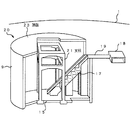
図3に示すように、連続地中壁9をそのまま側壁として利用し、底部に逆止弁(図3では図示せず)を有する底版15を形成し、流入水路工19および階段式減勢工17を設置する。流入水路工19は雨水管渠工18に連結される。洪水時等では、雨水は雨水管渠工18から流入水路工19および階段式減勢工17を介して地下式調整池20の内部に一時貯蔵される。
【0009】
さらに、図4に示すように、支柱21を設置し、地下式調整池20の上部に頂版23を形成する。そして、図5に示すように、頂版23の上部を覆土31で埋め戻し、地下式調整池20を構築する。図5では、階段式水路減勢工17、雨水管渠工18および流入水路工19等は図示しておらず、粘土層等の止水層33の上に透水層34が存在する。
【0010】
図5に示すように、底版15は逆止弁24を有する。また、底版15の下部には集水層25が設けられる。通常時では、集水層25に流入した地下水が、逆止弁24を介して地下式調整池20の内部へ流入するので、底版15には浮力がかからなくなる。流入した地下水は、集水ピット27に備え付けられた揚水ポンプ29で吸い上げられ、排水パイプ30を介して外部へ排出される。
【0011】
洪水時等では、雨水管渠工18の雨水が流入水路工19、階段式減勢工17を介して地下式調整池20内部に貯留される。この場合、逆止弁24の作用により地下式調整池20内部から、地下式調整池20の外部に向けて雨水が流出することはない。洪水が終了した段階で、地下式調整池20内に貯留された雨水は揚水ポンプ29により外部に排出される。
【0012】
尚、連続地中壁9の長さは、底版15からの地下水流入量、揚水ポンプ29の排水能力等によって決定され、必ずしも止水層33に到達させる必要はない。
このように、底版15から地下水を流入させて浮力を低減することにより、底版15や連続地中壁9の厚さを薄くすることができる。
【0013】
尚、本発明の技術範囲は、前述した実施の形態に限られるものではない。例えば、支柱21のない構造にしたり、頂版23をドーム屋根とすることもできる。減勢工を、階段式減勢工17に限らず、垂直落下式、急流工式、螺旋式とすることができる。連続地中壁9の内部に新たに側壁を構築し、連続地中壁9を側壁の一部として利用する場合もある。また、地下式調整池20を円筒状でなく、角柱状に形成することもできる。また、本発明に係る地下貯留構造物は、地下式調整池以外にも利用することができる。
【0014】
【発明の効果】
以上、詳細に説明したように、本発明によれば、部材厚が薄く、必要用地が狭く、経済性に優れた地下貯留構造物の構築方法および地下貯留構造物を提供できる。
【図面の簡単な説明】
【図1】連続地中壁の設置状況を示す図
【図2】連続地中壁内部の掘削状況を示す図
【図3】地下式調整池20の施工状況を示す図
【図4】地下式調整池20の施工状況を示す図
【図5】地下式調整池20の立断面図
【符号の説明】
9………連続地中壁
15………底版
18………雨水管渠工
19………流入水路工
20………地下式調整池
23………頂版
24………逆止弁
25………集水層
29………揚水ポンプ
31………覆土
33………止水層[0001]
BACKGROUND OF THE INVENTION
The present invention relates to a method for constructing an underground storage structure that uses a continuous underground wall as a side wall, and an underground storage structure.
[0002]
[Prior art]
Conventionally, underground storage structures such as underground adjustment ponds are constructed with a continuous underground wall as a retaining member, and after excavating the interior, the main body is driven on site or using a precast member Is building. In this case, the lifting of the structure due to the buoyancy of the groundwater is dealt with by the weight of the structure or the covering soil. In addition, for insufficient ground bearing capacity, the ground is improved or pile foundations are used.
[0003]
[Problems to be solved by the invention]
However, in order to resist buoyancy by the weight of the structure, it is necessary to increase the thickness of the structural members, which increases the construction cost. In addition, there is a method of securing the volume by reducing the water depth relative to the groundwater level and widening the bottom area of the structure, but a large site is required.
[0004]
The present invention has been made in view of such problems, and the object thereof is to provide a method for constructing an underground storage structure and an underground storage structure that are thin in member thickness, have a small required site, and are excellent in economy. To provide things.
[0005]
[Means for Solving the Problems]
A first invention for achieving the above-described object includes a step of providing a continuous underground wall in the ground, a step of excavating the inside of the continuous underground wall, and a check valve inside the continuous underground wall. And a step of providing a bottom slab having an underground storage structure comprising the continuous underground wall and the bottom slab.
In the first invention, a continuous underground wall is provided in the ground, and after excavating the inside of the continuous underground wall, a bottom plate having a check valve is installed, and an underground storage structure is formed by the continuous underground wall and the bottom plate. To do.
The second invention comprises: a continuous underground wall provided in the ground; and a bottom plate having a check valve provided in the continuous underground wall by excavating the continuous underground wall. It is a characteristic underground storage structure.
In the underground storage structure according to the second aspect of the present invention, water normally flows into the inside from the check valve, so that buoyancy is not applied to the bottom plate.
[0006]
[Means for Solving the Problems]
A first invention for achieving the above-described object includes a step of providing a continuous underground wall in the ground, a step of excavating the inside of the continuous underground wall, and a check valve inside the continuous underground wall. An underground storage structure in which underground water flows into the interior through the check valve by the continuous underground wall and the bottom plate. It is a construction method of things. In the first invention, a continuous underground wall is provided in the ground, and after excavating the inside of the continuous underground wall, a bottom plate having a check valve is installed, and an underground storage structure is formed by the continuous underground wall and the bottom plate. To do. The second invention comprises a continuous underground wall provided in the ground, the underground diaphragm walls inside is drilled, and a bottom plate having a check valve provided inside the underground diaphragm walls, the groundwater Flows into the inside through the check valve . In the underground storage structure according to the second aspect of the present invention, water normally flows into the inside from the check valve, so that buoyancy is not applied to the bottom plate.
[0007]
Concrete or the like is placed in the groove 3 to form a continuous
[0008]
As shown in FIG. 3, the continuous
[0009]
Further, as shown in FIG. 4, the
[0010]
As shown in FIG. 5, the
[0011]
During a flood or the like, rainwater from the
[0012]
The length of the continuous
Thus, the thickness of the
[0013]
The technical scope of the present invention is not limited to the embodiment described above. For example, a structure without the
[0014]
【The invention's effect】
As described above in detail, according to the present invention, it is possible to provide a method for constructing an underground storage structure and an underground storage structure that are thin in member thickness, have a small required site, and are excellent in economy.
[Brief description of the drawings]
[Fig. 1] Diagram showing the installation status of the continuous underground wall [Fig. 2] Diagram showing the excavation status inside the continuous underground wall [Fig. 3] Diagram showing the construction status of the underground pond 20 [Fig. The figure which shows the construction situation of adjustment pond 20 [Figure 5] Elevated cross section of
9 ……… Continuous
Claims (4)
前記連続地中壁の内部を掘削する工程と、
前記連続地中壁内部に逆止弁を有する底版を設ける工程と、
を具備し、
前記連続地中壁と前記底版とにより、地下水が前記逆止弁を介して内部に流入する地下貯留構造物を形成することを特徴とする地下貯留構造物の構築方法。Providing a continuous underground wall in the ground;
Excavating the interior of the continuous underground wall;
Providing a bottom plate having a check valve inside the continuous underground wall;
Comprising
A construction method for an underground storage structure, wherein the continuous underground wall and the bottom plate form an underground storage structure into which groundwater flows into the interior through the check valve .
前記連続地中壁内部が掘削され、前記連続地中壁内部に設けられる逆止弁を有する底版と、
を具備し、
地下水が前記逆止弁を介して内部に流入することを特徴とする地下貯留構造物。A continuous underground wall provided in the ground;
A bottom plate having a check valve excavated inside the continuous underground wall and provided inside the continuous underground wall;
Equipped with,
An underground storage structure in which groundwater flows into the inside through the check valve .
Priority Applications (1)
| Application Number | Priority Date | Filing Date | Title |
|---|---|---|---|
| JP2000265242A JP3777085B2 (en) | 2000-09-01 | 2000-09-01 | Construction method of underground storage structure and underground storage structure |
Applications Claiming Priority (1)
| Application Number | Priority Date | Filing Date | Title |
|---|---|---|---|
| JP2000265242A JP3777085B2 (en) | 2000-09-01 | 2000-09-01 | Construction method of underground storage structure and underground storage structure |
Publications (2)
| Publication Number | Publication Date |
|---|---|
| JP2002070047A JP2002070047A (en) | 2002-03-08 |
| JP3777085B2 true JP3777085B2 (en) | 2006-05-24 |
Family
ID=18752530
Family Applications (1)
| Application Number | Title | Priority Date | Filing Date |
|---|---|---|---|
| JP2000265242A Expired - Fee Related JP3777085B2 (en) | 2000-09-01 | 2000-09-01 | Construction method of underground storage structure and underground storage structure |
Country Status (1)
| Country | Link |
|---|---|
| JP (1) | JP3777085B2 (en) |
Families Citing this family (5)
| Publication number | Priority date | Publication date | Assignee | Title |
|---|---|---|---|---|
| JP4603852B2 (en) * | 2004-10-27 | 2010-12-22 | 東京都下水道サービス株式会社 | Structure to prevent floating of buried objects |
| JP5919047B2 (en) * | 2012-03-14 | 2016-05-18 | 株式会社カナサシテクノサービス | Underground water tank |
| JP2013249655A (en) * | 2012-06-01 | 2013-12-12 | Hayashi Bussan Hatsumei Kenkyusho:Kk | Storage tank subjected to buoyancy countermeasure |
| JP7175574B2 (en) * | 2018-11-27 | 2022-11-21 | 鹿島建設株式会社 | Structures for waste disposal |
| JP7240279B2 (en) * | 2019-07-22 | 2023-03-15 | 鹿島建設株式会社 | Underground reservoir |
-
2000
- 2000-09-01 JP JP2000265242A patent/JP3777085B2/en not_active Expired - Fee Related
Also Published As
| Publication number | Publication date |
|---|---|
| JP2002070047A (en) | 2002-03-08 |
Similar Documents
| Publication | Publication Date | Title |
|---|---|---|
| CN216640547U (en) | Drainage decompression anti-floating system suitable for weak permeable soft soil stratum | |
| CN111705825B (en) | Drainage and landing permanent-temporary integrated construction method for underground deep foundation pit | |
| CN102535488B (en) | Waterproof construction method for bottom plate of high-water-level basement | |
| CN111236284B (en) | A method and structure for draining groundwater from the bottom and surrounding areas of a basement | |
| CN115748774A (en) | Non-closed dewatering system for deep foundation pit plate lowering area in water-rich area and construction method | |
| CN110409420B (en) | Underground continuous wall with pit facing surface and precipitation function | |
| WO2009137848A2 (en) | A well and a method of constructing a well | |
| CN112195980A (en) | Water-resisting pressure-controlling anti-floating structure and construction method | |
| CN209741880U (en) | A deep foundation pit drainage structure | |
| KR100665984B1 (en) | Trench Type Natural Drainage Construction Method for Reducing Upward Pressure of Buildings | |
| CN211036962U (en) | Underground continuous wall with pit-facing surface and dewatering function | |
| CN210947085U (en) | Basement with drainage structure | |
| JP2002070047A (en) | Construction method of underground storage structure and underground storage structure | |
| CN110924381A (en) | Seepage-proofing structure of geotechnical engineering side slope | |
| CN211547830U (en) | Structure for preventing ground from being wetted | |
| CN212052829U (en) | Basement bottom and groundwater all around draw row structure | |
| KR100665985B1 (en) | Natural Drainage Construction Method for Reducing Upward Pressure of Buildings | |
| CN218028035U (en) | Basement construction drainage system | |
| CN217679214U (en) | Local deepened structure under building foundation | |
| CN120486405B (en) | Coral reef limestone geological foundation pit and construction method thereof | |
| JP3002436B2 (en) | Rainwater outflow prevention facility | |
| CN218437176U (en) | Antiskid stone retaining wall that moves that sets up in civil engineering foundation ditch | |
| CN221989402U (en) | A basement drainage pressure-reducing and anti-floating structure | |
| CN221702472U (en) | Rainwater pressure relief well structure based on weak soil body foundation ditch fertilizer groove that permeates water | |
| CN222771596U (en) | A seepage well integrating support and drainage |
Legal Events
| Date | Code | Title | Description |
|---|---|---|---|
| A977 | Report on retrieval |
Free format text: JAPANESE INTERMEDIATE CODE: A971007 Effective date: 20051017 |
|
| A131 | Notification of reasons for refusal |
Free format text: JAPANESE INTERMEDIATE CODE: A131 Effective date: 20051025 |
|
| A521 | Written amendment |
Free format text: JAPANESE INTERMEDIATE CODE: A523 Effective date: 20051219 |
|
| TRDD | Decision of grant or rejection written | ||
| A01 | Written decision to grant a patent or to grant a registration (utility model) |
Free format text: JAPANESE INTERMEDIATE CODE: A01 Effective date: 20060221 |
|
| A61 | First payment of annual fees (during grant procedure) |
Free format text: JAPANESE INTERMEDIATE CODE: A61 Effective date: 20060224 |
|
| R150 | Certificate of patent or registration of utility model |
Free format text: JAPANESE INTERMEDIATE CODE: R150 |
|
| FPAY | Renewal fee payment (event date is renewal date of database) |
Free format text: PAYMENT UNTIL: 20120303 Year of fee payment: 6 |
|
| LAPS | Cancellation because of no payment of annual fees |