JP3775406B2 - Recording apparatus and reciprocating recording position adjusting method - Google Patents
Recording apparatus and reciprocating recording position adjusting method Download PDFInfo
- Publication number
- JP3775406B2 JP3775406B2 JP2003330297A JP2003330297A JP3775406B2 JP 3775406 B2 JP3775406 B2 JP 3775406B2 JP 2003330297 A JP2003330297 A JP 2003330297A JP 2003330297 A JP2003330297 A JP 2003330297A JP 3775406 B2 JP3775406 B2 JP 3775406B2
- Authority
- JP
- Japan
- Prior art keywords
- recording
- amplitude difference
- inspection pattern
- value
- inspection
- Prior art date
- Legal status (The legal status is an assumption and is not a legal conclusion. Google has not performed a legal analysis and makes no representation as to the accuracy of the status listed.)
- Expired - Fee Related
Links
Images


Classifications
-
- B—PERFORMING OPERATIONS; TRANSPORTING
- B41—PRINTING; LINING MACHINES; TYPEWRITERS; STAMPS
- B41J—TYPEWRITERS; SELECTIVE PRINTING MECHANISMS, i.e. MECHANISMS PRINTING OTHERWISE THAN FROM A FORME; CORRECTION OF TYPOGRAPHICAL ERRORS
- B41J2/00—Typewriters or selective printing mechanisms characterised by the printing or marking process for which they are designed
- B41J2/005—Typewriters or selective printing mechanisms characterised by the printing or marking process for which they are designed characterised by bringing liquid or particles selectively into contact with a printing material
- B41J2/01—Ink jet
- B41J2/015—Ink jet characterised by the jet generation process
- B41J2/04—Ink jet characterised by the jet generation process generating single droplets or particles on demand
- B41J2/045—Ink jet characterised by the jet generation process generating single droplets or particles on demand by pressure, e.g. electromechanical transducers
- B41J2/04501—Control methods or devices therefor, e.g. driver circuits, control circuits
- B41J2/04505—Control methods or devices therefor, e.g. driver circuits, control circuits aiming at correcting alignment
-
- B—PERFORMING OPERATIONS; TRANSPORTING
- B41—PRINTING; LINING MACHINES; TYPEWRITERS; STAMPS
- B41J—TYPEWRITERS; SELECTIVE PRINTING MECHANISMS, i.e. MECHANISMS PRINTING OTHERWISE THAN FROM A FORME; CORRECTION OF TYPOGRAPHICAL ERRORS
- B41J2/00—Typewriters or selective printing mechanisms characterised by the printing or marking process for which they are designed
- B41J2/005—Typewriters or selective printing mechanisms characterised by the printing or marking process for which they are designed characterised by bringing liquid or particles selectively into contact with a printing material
- B41J2/01—Ink jet
- B41J2/015—Ink jet characterised by the jet generation process
- B41J2/04—Ink jet characterised by the jet generation process generating single droplets or particles on demand
- B41J2/045—Ink jet characterised by the jet generation process generating single droplets or particles on demand by pressure, e.g. electromechanical transducers
- B41J2/04501—Control methods or devices therefor, e.g. driver circuits, control circuits
- B41J2/0458—Control methods or devices therefor, e.g. driver circuits, control circuits controlling heads based on heating elements forming bubbles
-
- B—PERFORMING OPERATIONS; TRANSPORTING
- B41—PRINTING; LINING MACHINES; TYPEWRITERS; STAMPS
- B41J—TYPEWRITERS; SELECTIVE PRINTING MECHANISMS, i.e. MECHANISMS PRINTING OTHERWISE THAN FROM A FORME; CORRECTION OF TYPOGRAPHICAL ERRORS
- B41J29/00—Details of, or accessories for, typewriters or selective printing mechanisms not otherwise provided for
- B41J29/38—Drives, motors, controls or automatic cut-off devices for the entire printing mechanism
- B41J29/393—Devices for controlling or analysing the entire machine ; Controlling or analysing mechanical parameters involving printing of test patterns
Description
本発明は、記録ヘッドの往路記録および復路記録を重ねる双方向記録により記録媒体上に記録を行う記録装置、およびそのような記録装置において、往路記録に対する復路記録の記録位置を調整する往復記録位置調整方法に関する。 The present invention relates to a recording apparatus that performs recording on a recording medium by bidirectional recording in which forward recording and backward recording of a recording head are superimposed, and in such a recording apparatus, a reciprocal recording position that adjusts a recording position of backward recording with respect to forward recording. It relates to the adjustment method.
従来より、複数のインクジェットノズルを有する記録ヘッドをキャリッジにより往復移動させて、記録ヘッドによる往路記録(往方向記録)および復路記録(復方向記録)を重ねることで記録媒体上に記録を行う記録装置(所謂、双方向記録プリンタ)が、実用化されている。 2. Description of the Related Art Conventionally, a recording apparatus that performs recording on a recording medium by reciprocating a recording head having a plurality of inkjet nozzles with a carriage and superimposing forward recording (forward recording) and backward recording (reverse recording) by the recording head A so-called bidirectional recording printer has been put into practical use.
しかし、このような双方向記録を行うプリンタにおいては、往路記録と復路記録とにおいて記録位置ズレ(印字位置ズレ)が生じる場合があるという問題がある。なお、記録位置ズレは、往方向移動時と復方向移動時においてキャリッジ駆動機構にバックラッシュが存在すること、往路記録(往行印字)に際して噴射したインクが用紙に付着する往路記録位置と、復路記録(復行印字)に際して噴射したインクが用紙に付着する復路記録位置とに位置ズレが発生すること、往路記録速度と復路記録速度とが微妙に異なること、等の要因により発生する。 However, in a printer that performs such bidirectional recording, there is a problem that a recording position deviation (printing position deviation) may occur between forward pass recording and backward pass recording. It should be noted that the recording position misalignment is the presence of backlash in the carriage drive mechanism during forward movement and backward movement, the forward recording position where ink ejected during forward recording (forward printing) adheres to the paper, and the backward path. This occurs due to factors such as the occurrence of positional deviation from the return pass recording position where the ink ejected during recording (return printing) adheres to the paper, the forward pass recording speed and the return pass recording speed being slightly different.
このため、このような記録位置ズレを解消するために、種々の発明が提案されている。
例えば、下記の特許文献1には、双方行記録により記録される検査パターン(パッチ)として、往路記録に対する復路記録の記録位置を所定量ずつ変化させた複数の検査パターン(パッチ)を記録し、複数の検査パターン(パッチ)のそれぞれの濃度データに基づき、最適記録位置(最適プリント位置)を判定するプリント位置合わせ方法およびプリント装置が提案されている。より具体的には、複数の検査パターン(パッチ)のそれぞれについて、複数点(12カ所)での濃度データを測定するとともにそれらの濃度データの平均値を演算(算出)し、そして、記録位置条件と濃度データ平均値との関係に基づいて、濃度が最も高くなる記録位置を、最適記録位置(最適プリント位置)として選択している。
For this reason, various inventions have been proposed in order to eliminate such a recording position shift.
For example, in
なお、複数点(12カ所)における濃度データの平均値を演算(算出)する際には、各検査パターン(パッチ)ごとに濃度データの最小値と最大値との差分値を算出し、その差分値が所定のしきい値よりも大きい場合には、濃度むらが生じていると判断して、その検査パターン(パッチ)の濃度データを除いて、最適プリント位置を判定している。
しかし、上記従来の記録位置合わせ方法では、検査パターン(パッチ)における濃度データの測定位置を考慮することなく、複数箇所での濃度データに基づき最適な記録位置を判定するため、人間の目視による判定結果とは異なる判定結果が導き出される場合があるという問題がある。 However, in the above conventional recording position alignment method, the optimum recording position is determined based on the density data at a plurality of locations without considering the density data measurement position in the inspection pattern (patch). There is a problem that a determination result different from the result may be derived.
つまり、隣接する濃度データが徐々に変化している検査パターン(パッチ)については、隣接する濃度データの変化量が小さい場合においては、人間の目視による判定においては、記録位置ズレが無いと判定できるとともに、最適記録位置での検査パターン(最良検査パターン)と判定できる場合がある。しかし、そのような検査パターンであっても、互いに離れた測定位置における濃度データどうしの差分値が大きい場合には、上記従来の方法では、濃度むらが生じていると判定されてしまい、最良検査パターンであると判定されることはない。 That is, with respect to the inspection pattern (patch) in which the adjacent density data is gradually changing, it can be determined that there is no recording position shift in the human visual determination when the change amount of the adjacent density data is small. At the same time, it may be determined that the inspection pattern at the optimum recording position (best inspection pattern). However, even with such an inspection pattern, if the difference value between the density data at the measurement positions that are separated from each other is large, it is determined that density unevenness has occurred in the conventional method, and the best inspection is performed. It is not determined to be a pattern.
また、一時的なノイズなどの影響により一部の濃度データが大きく変化しているものの、検査パターンの全体的な記録状態としては記録位置ズレが生じていない場合には、人間の目視による判定では、記録位置ズレが生じていないと判定できるとともに、最良検査パターンと判定できる場合がある。しかし、そのような検査パターンであっても、ノイズ部分の濃度データとその他の濃度データとの差分値が大きい場合には、上記従来の方法では、濃度むらが生じていると判定され、最良検査パターンであると判定されることはない。 In addition, although some density data has changed greatly due to the effects of temporary noise, etc., but there is no recording position deviation as the overall recording state of the inspection pattern, human visual judgment In some cases, it can be determined that there is no recording position deviation, and the best inspection pattern can be determined. However, even with such an inspection pattern, if the difference value between the density data of the noise portion and the other density data is large, it is determined that density unevenness has occurred in the conventional method, and the best inspection is performed. It is not determined to be a pattern.
他方、濃度データの最大値と最小値との差分値が大きくない検査パターンであっても、近接する検出箇所どうしの濃度データの変化量が大きい場合には、人間の目視判定では記録位置ズレが生じていると判定される場合がある。しかし、そのような検査パターンであっても、濃度データの最大値と最小値との差分値が他の検査パターンよりも小さい場合には、上記従来の方法では、最良検査パターンとして判定される可能性がある。 On the other hand, even if the difference between the maximum value and the minimum value of the density data is not large, if the amount of change in the density data between adjacent detection points is large, the human visual judgment may cause a recording position shift. It may be determined that it has occurred. However, even in such an inspection pattern, if the difference value between the maximum value and the minimum value of the density data is smaller than other inspection patterns, the above-described conventional method can be determined as the best inspection pattern. There is sex.
このように人間の目視による判定結果とは異なる判定結果となる場合、そのような判定結果に基づき設定された記録位置で記録された結果物は、人間にとっては記録ズレが生じている不適切な結果物と感じられるという問題が生じる。 In this way, when the determination result is different from the human visual determination result, the result recorded at the recording position set based on such a determination result is inappropriate for humans because of the recording deviation. The problem of being felt as a result arises.
そこで、本発明は、こうした問題に鑑みなされたものであり、双方行記録を行う記録装置であって、往路記録に対する復路記録の記録位置を調整する際に記録位置ズレを判定するにあたり、人間の目視による判定結果に近い判定結果を得られる記録装置を提供し、およびそのような記録装置での往復記録位置調整方法を提供することを目的とする。 Accordingly, the present invention has been made in view of these problems, and is a recording apparatus that performs both-line recording, and in determining the recording position deviation when adjusting the recording position of the backward recording with respect to the outward recording, It is an object of the present invention to provide a recording apparatus capable of obtaining a determination result close to a visual determination result, and to provide a reciprocating recording position adjustment method in such a recording apparatus.
かかる目的を達成するためになされた請求項1に記載の発明は、複数のインクジェットノズルを有する記録ヘッドをキャリッジにより往復移動させて、記録ヘッドの往路記録および復路記録を重ねる双方向記録により記録媒体上に記録を行う記録手段を備える記録装置であって、記録手段を用いた双方向記録により複数の縦罫線を有する検査パターンを記録するに際し、往路記録と復路記録との記録位置を相対的に異ならせた複数の検査パターンを記録媒体上に形成する検査パターン記録手段と、記録媒体に向かって発光する発光部と、記録媒体からの反射光を受光する受光部とを有し、キャリッジの移動方向に対して平行に移動するセンサと、当該センサを各検査パターンの一端部から他端部にかけて移動させると共に、受光部が受光した反射光に基づいて各検査パターンの濃淡度合いを表す濃度データを取得する濃度データ検出手段と、各検査パターンについて取得した各濃度データから、所定の部分判定区間に含まれる部分データを複数抽出し、各部分判定区間について部分データの最小値および最大値を検出するとともに、部分データの最小値と最大値との差分を濃度振幅値として検出する濃度振幅検出手段と、各検査パターンについて、各部分判定区間のうち隣接する部分判定区間どうしの濃度振幅値の差分を振幅差分値として検出する振幅差分検出手段と、当該振幅差分検出手段により検出された振幅差分値に基づき、各検査パターンの濃度データの変化量を判断し、各検査パターンのうち濃度データの変化量が最小となる検査パターンを最良検査パターンと判定する最良パターン判定手段と、当該最良パターン判定手段により最良検査パターンと判定された検査パターンの往路記録と復路記録との記録位置を、記録を行う際の記録位置として設定する記録位置設定手段と、を備えることを特徴とする記録装置である。
In order to achieve this object, the invention according to
また、上記目的を達成するためになされた請求項7に記載の発明方法は、複数のインクジェットノズルを有する記録ヘッドをキャリッジにより往復移動させて、記録ヘッドの往路記録および復路記録を重ねる双方向記録により記録媒体上に記録を行う記録装置において、往路記録に対する復路記録の記録位置を調整する往復記録位置調整方法であって、双方向記録により複数の縦罫線を有する検査パターンを記録するに際し、往路記録に対する復路記録の記録位置が異なる複数の検査パターンを記録する第1工程と、各検査パターンについて、記録ヘッドの往復方向における検査パターンの一端部から他端部にかけて、検査パターンに対して光を照射すると共に検査パターンからの反射光を受光して、該反射光に基づいて検査パターンの濃淡度合いを表す濃度データを取得する第2工程と、各検査パターンについて取得した各濃度データから、所定の部分判定区間に含まれる部分データを複数抽出し、各部分判定区間について部分データの最小値および最大値を検出するとともに、部分データの最小値と最大値との差分を濃度振幅値として検出する第3工程と、各検査パターンについて、各部分判定区間のうち隣接する部分判定区間どうしの濃度振幅値の差分を振幅差分値として検出する第4工程と、第4工程において検出された振幅差分値に基づき、各検査パターンの濃度データの変化量を判断し、各検査パターンのうち濃度データの変化量が最小となる検査パターンを最良検査パターンと判定する第5工程と、第5工程において最良検査パターンと判定された検査パターンにおける往路記録に対する復路記録の記録位置を、記録を行う際の記録位置として設定する第6工程と、を有することを特徴とする往復記録位置調整方法である。
In addition, the invention method according to
本発明の記録装置および往復記録位置調整方法においては、検査パターンの濃度データの最大値・最小値に基づき、濃度データの最大値と最小値との差分(ピーク差分値)が最小となる最良検査パターンを判定するのではなく、濃度データの振幅差分値に基づき、複数の検査パターンの中から最良検査パターンを判定することに特徴がある。 In the recording apparatus and the reciprocating recording position adjusting method of the present invention, the best inspection in which the difference (peak difference value) between the maximum value and the minimum value of the density data is minimized based on the maximum value / minimum value of the density data of the inspection pattern. Instead of determining the pattern, it is characterized in that the best inspection pattern is determined from a plurality of inspection patterns based on the amplitude difference value of the density data.
ここで、濃度データの振幅差分値は、隣接する部分判定区間どうしの濃度振幅値の差分であることから、濃度データの変化量が大きい場合には振幅差分値は大きい値を示し、濃度データの変化量が小さい場合には振幅差分値は小さい値を示す。つまり、濃度データの振幅差分値は、濃度データの変化量が反映された値を示す。このことから、振幅差分値に基づいて検査パターンにおける濃度データの変化量が小さいと判断できる検査パターンは、記録位置ズレが生じていないと判定できる。 Here, since the amplitude difference value of the density data is the difference between the density amplitude values of the adjacent partial determination sections, the amplitude difference value indicates a large value when the change amount of the density data is large. When the amount of change is small, the amplitude difference value is small. That is, the amplitude difference value of the density data indicates a value reflecting the change amount of the density data. From this, an inspection pattern that can be determined that the change amount of the density data in the inspection pattern is small based on the amplitude difference value can be determined that there is no recording position deviation.
例えば、互いに離れた測定位置における濃度データどうしの差分値が大きい検査パターンであっても、濃度データが緩やかに変化する検査パターンにおいては、振幅差分値は全体的に小さい値となり、濃度データの変化量が小さいと判断できるため、記録位置ズレが無いと判定できる。なお、このように濃度データが緩やかに変化する検査パターンは、人間の目視判定では、記録位置ズレが無いと判定できることから、振幅差分値に基づく記録位置ズレの有無の判定結果は、人間の目視判定による判定結果に近い判定結果となる。 For example, even if the inspection pattern has a large difference value between density data at measurement positions that are separated from each other, the amplitude difference value is generally small in the inspection pattern in which the density data changes slowly, and the density data changes. Since it can be determined that the amount is small, it can be determined that there is no recording position shift. In addition, since the inspection pattern in which the density data gradually changes can be determined by the human visual determination that there is no recording position deviation, the determination result of the presence or absence of the recording position deviation based on the amplitude difference value is The determination result is close to the determination result by the determination.
また、一時的なノイズなどの影響により一部の濃度データが大きく変化している検査パターンであっても、全体的な記録状態としては記録位置ズレが生じていない検査パターンにおいては、振幅差分値は、ノイズ発生箇所では大きい値を示すが、そのほかの箇所では小さい値となり、濃度データの変化量が小さいと判断できるため、記録位置ズレが無いと判定できる。このように濃度データの一部にノイズの影響が生じている検査パターンは、人間の目視判定では、記録位置ズレが無いと判定できることから、振幅差分値に基づく記録位置ズレの有無の判定結果は、人間の目視判定による判定結果と比較した場合、略同様の判定結果となる。 In addition, even in a test pattern in which some density data changes greatly due to the influence of temporary noise or the like, the amplitude difference value is used in a test pattern in which the recording position does not shift as an overall recording state. Indicates a large value at a noise occurrence location, but a small value at other locations and it can be determined that the amount of change in density data is small, so that it can be determined that there is no recording position deviation. Since the inspection pattern in which the influence of noise occurs in a part of the density data in this manner can be determined by human visual determination that there is no recording position deviation, the determination result of the presence or absence of the recording position deviation based on the amplitude difference value is When compared with the determination result by human visual determination, the determination result is substantially the same.
さらに、他の検査パターンと比べて濃度データの最大値と最小値との差分値が小さい検査パターンであっても、近接する検出箇所どうしの濃度データの変化量が大きい検査パターンにおいては、振幅差分値は、濃度データの変化量が大きい箇所では大きい値を示すことから、濃度データの変化量が大きいと判断できるため、記録位置ズレが生じていると判定できる。このように近接する検出箇所どうしの濃度データの変化量が大きい検査パターンは、人間の目視判定では、記録位置ズレが生じていると判定できることから、振幅差分値に基づく記録位置ズレの有無の判定結果は、人間の目視判定による判定結果と比較した場合、略同様の判定結果となる。 Furthermore, even if the difference between the maximum value and the minimum value of the density data is small compared to other inspection patterns, the amplitude difference is large in the inspection pattern in which the amount of change in density data between adjacent detection points is large. Since the value shows a large value at a portion where the change amount of the density data is large, it can be determined that the change amount of the density data is large, and therefore it can be determined that a recording position shift has occurred. Since the inspection pattern having such a large amount of change in density data between adjacent detection points can be determined to have a recording position shift in human visual determination, determination of the presence or absence of a recording position shift based on the amplitude difference value. The result is substantially similar to the determination result when compared with the determination result by human visual determination.
なお、従来のように、濃度データの最大値・最小値に基づき、濃度データのピーク差分値が最小となる最良検査パターンを判定する場合においては、濃度データの連続性を考慮することなく、濃度データを離散的なデータとして用いることにより、記録位置ズレを判定している。これに対して、本発明のように、濃度データの振幅差分値に基づいて判定する場合には、濃度データの連続性を考慮しつつ、記録位置ズレを判定できることから、濃度データの最大値と最小値との差分(ピーク差分値)が大きい検査パターンであっても、濃度データが全体的に緩やかに変化する場合には、最良検査パターンとして判定できるという特徴がある。 When determining the best inspection pattern that minimizes the peak difference value of density data based on the maximum value / minimum value of density data as in the past, the density data is not considered without considering the continuity of density data. The recording position deviation is determined by using the data as discrete data. On the other hand, when determining based on the amplitude difference value of the density data as in the present invention, the recording position deviation can be determined while considering the continuity of the density data. Even if the test pattern has a large difference (peak difference value) from the minimum value, it can be determined as the best test pattern if the density data changes slowly as a whole.
よって、本発明によれば、濃度データの振幅差分値に基づいて判定するため、濃度データが全体的に緩やかに変化する検査パターン等であっても、最良検査パターンとして判定することができ、人間の判定結果に近い判定結果を得ることができる。 Therefore, according to the present invention, since the determination is based on the amplitude difference value of the density data, it is possible to determine even the test pattern etc. in which the density data changes gradually as a best test pattern. A determination result close to the determination result can be obtained.
なお、部分判定区間は、その幅寸法が検査パターンにおける複数の縦罫線の間隔寸法よりも長くなるように、予め定めておくとよい。具体的には、部分判定区間の中に、濃度データの波形における極大値および極小値が少なくとも1つずつ含むように、部分判定区間の幅寸法を設定することが望ましい。 The partial determination section may be determined in advance such that the width dimension is longer than the interval dimension between the plurality of vertical ruled lines in the inspection pattern. Specifically, it is desirable to set the width dimension of the partial determination section so that the partial determination section includes at least one maximum value and minimum value in the waveform of the density data.
また、検査パターンにおける部分判定区間の設定箇所は、例えば、検査パターンの一端部から他端部にわたり予め定められた部分検知間隔ごとの複数箇所に設定するとよい。つまり、各検査パターンについて、検査パターンの一端部から他端部にわたる濃度データにおいて、部分検知間隔ごとに複数の部分判定区間を設定し、各部分判定区間に含まれる部分データをそれぞれ抽出するのである。 Moreover, it is good to set the setting location of the partial determination area in a test | inspection pattern in the several location for every predetermined partial detection interval from the one end part of a test | inspection pattern to the other end part, for example. That is, for each inspection pattern, in the density data extending from one end to the other end of the inspection pattern, a plurality of partial determination sections are set for each partial detection interval, and the partial data included in each partial determination section is extracted. .
このとき、部分検知間隔は、部分判定区間の幅寸法と同一寸法に設定しても良く、あるいは、部分判定区間の幅寸法よりも短く設定し、隣接する部分判定区間どうしに重複部分が生じるように設定しても良い。 At this time, the partial detection interval may be set to the same dimension as the width dimension of the partial determination section, or may be set to be shorter than the width dimension of the partial determination section so that an overlapping portion is generated between adjacent partial determination sections. It may be set to.
なお、同一寸法の検査パターンについて判定する場合には、部分検知間隔を短く設定することで、部分判定区間の個数を増やすことができ、振幅差分値をより多く抽出できる。このことから、部分検知間隔を短く設定することにより、振幅差分値をより高い精度で抽出できるとと共に、検査パターンの判定精度の向上を図ることができる。 When determining inspection patterns having the same dimensions, by setting the partial detection interval short, the number of partial determination sections can be increased, and more amplitude difference values can be extracted. Therefore, by setting the partial detection interval short, the amplitude difference value can be extracted with higher accuracy, and the inspection pattern determination accuracy can be improved.
そして、上記の記録装置においては、請求項2に記載のように、振幅差分検出手段は、検査パターンの全領域において、複数の振幅差分値を検出し、最良パターン判定手段は、各検査パターンについて、複数の振幅差分値のうち最大値を振幅差分最大値として抽出し、各検査パターンのうち振幅差分最大値が最小となる検査パターンを最良検査パターンと判定するとよい。
In the recording apparatus, as described in
また、上記の往復記録位置調整方法においては、請求項8に記載のように、第4工程では、検査パターンの全領域において、複数の振幅差分値を検出し、第5工程では、各検査パターンについて、複数の振幅差分値のうち最大値を振幅差分最大値として抽出し、各検査パターンのうち振幅差分最大値が最小となる検査パターンを最良検査パターンと判定するとよい。
In the above-described reciprocal recording position adjustment method, as described in
このように、検査パターンの全領域において複数の振幅差分値を検出することにより、振幅差分値の全体的な変化状態を把握できると共に、濃度データの全体的な変化状態を把握することができる。 In this way, by detecting a plurality of amplitude difference values in the entire region of the inspection pattern, it is possible to grasp the overall change state of the amplitude difference value and to grasp the overall change state of the density data.
そして、複数の振幅差分値のうち最大値となる振幅差分最大値は、その検査パターンにおける濃度データの変化量のうちの最大値(変化量最大値)に比例した値を示すと共に、その検査パターンにおける記録位置ズレのうち最も大きいズレ量(記録位置ズレ量最大値)に比例した値を示す。 The maximum amplitude difference value among the plurality of amplitude difference values indicates a value proportional to the maximum value (maximum change amount) of the change amount of the density data in the inspection pattern, and the inspection pattern. A value proportional to the largest deviation amount (maximum recording position deviation amount) among the recording position deviations in FIG.
このことから、複数の検査パターンについて振幅差分最大値をそれぞれ比較し、振幅差分最大値が最も小さい検査パターンを判定することにより、最も記録位置ズレが小さい検査パターンを抽出することができる。 From this, it is possible to extract the inspection pattern with the smallest recording position shift by comparing the maximum amplitude difference values for a plurality of inspection patterns and determining the inspection pattern with the smallest amplitude difference maximum value.
よって、本発明によれば、濃度データの全体的な変化状態を把握できると共に、最も記録位置ズレが小さい検査パターンを抽出できることから、検査パターンの濃度データが全体的に緩やかに変化する検査パターンであっても、最良検査パターンとして判定でき、人間の感覚に近い判定結果を得ることができる。 Therefore, according to the present invention, the overall change state of the density data can be grasped, and the test pattern with the smallest recording position deviation can be extracted. Even if it exists, it can determine as a best test | inspection pattern and the determination result close | similar to a human sense can be obtained.
次に、上述の記録装置においては、請求項3に記載のように、振幅差分検出手段は、検査パターンの一部領域において、複数の振幅差分値を検出し、最良パターン判定手段は、各検査パターンについて、複数の振幅差分値の平均値を部分振幅差分平均値として抽出し、各検査パターンのうち部分振幅差分平均値が最小となる検査パターンを最良検査パターンと判定するとよい。 Next, in the above-described recording apparatus, as described in claim 3, the amplitude difference detection means detects a plurality of amplitude difference values in a partial region of the inspection pattern, and the best pattern determination means determines each inspection. For the pattern, an average value of a plurality of amplitude difference values may be extracted as a partial amplitude difference average value, and an inspection pattern having a minimum partial amplitude difference average value among the inspection patterns may be determined as the best inspection pattern.
また、上記の往復記録位置調整方法においては、請求項9に記載のように、第4工程では、検査パターンの一部領域において、複数の振幅差分値を検出し、第5工程では、各検査パターンについて、複数の振幅差分値の平均値を部分振幅差分平均値として抽出し、各検査パターンのうち部分振幅差分平均値が最小となる検査パターンを最良検査パターンと判定するとよい。 In the above-described reciprocal recording position adjustment method, as described in claim 9, in the fourth step, a plurality of amplitude difference values are detected in a partial region of the inspection pattern, and in the fifth step, each inspection is performed. For the pattern, an average value of a plurality of amplitude difference values may be extracted as a partial amplitude difference average value, and an inspection pattern having a minimum partial amplitude difference average value among the inspection patterns may be determined as the best inspection pattern.
このように、検査パターンの一部領域に限定して振幅差分値を検出することで、検査パターンの全領域について振幅差分値を検出する場合に比べて、検出データ量を低減できるため、機器の検出処理負荷を軽減することができ、処理速度を向上できる。 In this way, by detecting the amplitude difference value only in a partial region of the inspection pattern, the amount of detected data can be reduced compared to the case where the amplitude difference value is detected for the entire region of the inspection pattern. The detection processing load can be reduced, and the processing speed can be improved.
また、振幅差分値の検出対象となる一部領域を、ノイズなどの影響が生じやすい箇所以外に設定することにより、ノイズの影響を抑えつつ振幅差分値を検出することができ、判定精度の向上を図ることができる。 In addition, by setting a partial area to be detected as an amplitude difference value to a location other than where noise or other effects are likely to occur, the amplitude difference value can be detected while suppressing the influence of noise, and the determination accuracy is improved. Can be achieved.
あるいは、振幅差分値の検出対象となる一部領域を、検査パターンのうち濃度データの全体的な変化傾向が反映されやすい箇所に設定することで、濃度データの全体的な変化傾向を抽出でき、判定精度の低下を防ぐことができる。 Alternatively, by setting a partial area to be detected as an amplitude difference value to a location where the overall change tendency of the density data is easily reflected in the inspection pattern, the overall change tendency of the density data can be extracted. A decrease in determination accuracy can be prevented.
さらに、振幅差分値の検出対象となる一部領域を、検査パターンのうち記録位置ズレが生じやすい箇所に設定することで、記録位置ズレの検出精度を向上でき、記録位置(印字位置)の調整精度の向上を図ることができる。 Furthermore, by setting a partial area to be detected as an amplitude difference value at a location in the inspection pattern where the recording position deviation is likely to occur, the recording position deviation detection accuracy can be improved and the recording position (printing position) can be adjusted. The accuracy can be improved.
そこで、請求項3に記載の記録装置においては、例えば、請求項4に記載のように、振幅差分検出手段は、検査パターンのうち記録ヘッドの往復方向における一端部、中央部、他端部の3カ所について、振幅差分値を検出するとよい。
Therefore, in the recording apparatus according to claim 3, for example, as described in
また、請求項9に記載の往復記録位置調整方法においては、例えば、請求項10に記載のように、第4工程では、検査パターンのうち記録ヘッドの往復方向における一端部、中央部、他端部の3カ所について、振幅差分値を検出するとよい。
In the reciprocating recording position adjusting method according to claim 9, for example, as described in
このように検査パターンのうち一端部、中央部、他端部の3カ所は、互いに離れた位置に配置されていることから、これら3カ所の振幅差分値を用いることで、検査パターンのうち濃度データの全体的な変化傾向を捉えることができる。 As described above, since the three positions of the one end portion, the center portion, and the other end portion of the inspection pattern are arranged at positions separated from each other, the density difference value among the inspection patterns can be obtained by using the amplitude difference values of these three locations. It is possible to capture the overall change trend of data.
よって、本発明によれば、検査パターンのうち濃度データの全体的な変化傾向が反映されやすい箇所から振幅差分値を抽出することができ、最良検査パターンを判定するにあたり、検出処理負荷の軽減や処理速度の向上を図りつつ、人間の判定結果に近い判定結果を得ることができる。 Therefore, according to the present invention, it is possible to extract the amplitude difference value from the portion of the inspection pattern in which the overall change tendency of the density data is easily reflected, and in determining the best inspection pattern, the detection processing load can be reduced. A determination result close to a human determination result can be obtained while improving the processing speed.
次に、上述の記録装置においては、請求項5に記載のように、振幅差分検出手段は、検査パターンの全領域において、複数の振幅差分値を検出し、最良パターン判定手段は、各検査パターンについて、複数の振幅差分値の平均値を全体振幅差分平均値として抽出し、各検査パターンのうち全体振幅差分平均値が最小となる検査パターンを最良検査パターンと判定するとよい。
Next, in the above-described recording apparatus, as described in
また、上述の往復記録位置調整方法においては、請求項11に記載のように、第4工程では、検査パターンの全領域において、複数の振幅差分値を検出し、第5工程では、各検査パターンについて、複数の振幅差分値の平均値を全体振幅差分平均値として抽出し、各検査パターンのうち全体振幅差分平均値が最小となる検査パターンを最良検査パターンと判定するとよい。
Further, in the above-described reciprocal recording position adjusting method, as described in
このように、検査パターンの全領域において複数の振幅差分値を検出することにより、振幅差分値の全体的な変化状態を把握できると共に、濃度データの全体的な変化状態を把握することができる。 In this way, by detecting a plurality of amplitude difference values in the entire region of the inspection pattern, it is possible to grasp the overall change state of the amplitude difference value and to grasp the overall change state of the density data.
また、検査パターンの全領域における振幅差分値の平均値(全体振幅差分平均値)は、濃度データにノイズ等の影響による変動が生じた場合であっても、その変動の程度が小さい場合には、ノイズ等が無い時の全体振幅差分平均値と比べて、値が大幅に大きくなることはない。つまり、濃度データが全体として緩やかに変化する検査パターンにおいては、ノイズなどの影響が小さい場合には、全体振幅差分平均値は小さい値を示す。 In addition, the average value of the amplitude difference values (overall amplitude difference average value) in the entire region of the inspection pattern is the case where the fluctuation due to the influence of noise or the like occurs in the density data, but the degree of the fluctuation is small. Compared with the average value of the entire amplitude difference when there is no noise or the like, the value does not increase significantly. That is, in the test pattern in which the density data changes slowly as a whole, the average value of the overall amplitude difference shows a small value when the influence of noise or the like is small.
このように、濃度データが全体として緩やかに変化すると共にノイズなどの影響による変動が小さい検査パターンは、人間の目視判定においては、記録位置ズレが生じていないと判定できる。このため、全体振幅差分平均値に基づいて複数の検査パターンを判定することで、記録位置ズレが少ない最良な検査パターンを判定するにあたり、人間の判定結果に近い判定結果を得ることができる。 As described above, the inspection pattern in which the density data changes gently as a whole and the fluctuation due to the influence of noise or the like is small can be determined that there is no recording position deviation in human visual determination. For this reason, by determining a plurality of inspection patterns based on the overall amplitude difference average value, it is possible to obtain a determination result close to a human determination result in determining the best inspection pattern with little recording position deviation.
なお、ノイズなどの影響による濃度データの変動の程度が大きい場合には、ノイズ等が無い場合と比べて、振幅差分値は全体的に大きな値となるため、ノイズなどの影響を大きく受けた検査パターンは、全体振幅差分平均値が大きい値を示す。 Note that when the degree of fluctuation in density data due to the influence of noise is large, the amplitude difference value is generally large compared to the case where there is no noise or the like. The pattern indicates a value having a large overall amplitude difference average value.
このようなノイズなどの影響による変動が大きい検査パターンは、人間の目視判定においては、記録位置ズレが生じていると判定できる。このため、全体振幅差分平均値に基づいて複数の検査パターンを判定することで、記録位置ズレが生じている不良な検査パターンを最良な検査パターンであると誤って判定するのを避けることができ、人間の感覚に近い判定結果を得ることができる。 Such a test pattern having a large variation due to the influence of noise or the like can be determined to have a recording position shift in human visual determination. For this reason, by determining a plurality of inspection patterns based on the overall amplitude difference average value, it is possible to avoid erroneously determining that a defective inspection pattern in which a recording position shift has occurred is the best inspection pattern. It is possible to obtain a determination result close to a human sense.
よって、本発明によれば、突発的なノイズなどの影響を抑えつつ最良な検査パターンを判定できると共に、多大なノイズなどの影響を受けた不良な検査パターンを誤って最良な検査パターンと判定するのを防ぐことができ、人間の感覚に近い判定結果を得ることができる。 Therefore, according to the present invention, the best inspection pattern can be determined while suppressing the influence of sudden noise and the like, and a defective inspection pattern affected by a large amount of noise is erroneously determined as the best inspection pattern. Therefore, it is possible to obtain a determination result close to a human sense.
次に、上述の記録装置においては、請求項6に記載のように、振幅差分検出手段は、検査パターンの全領域において、複数の振幅差分値を検出し、最良パターン判定手段は、各検査パターンについて、複数の振幅差分値を昇順に並べて、最小値から予め定められた検出対象個数の振幅差分値を抽出し、抽出した検出対象個数の振幅差分値の平均値を最小昇順振幅差分平均値として検出し、最小昇順振幅差分平均値が最小となる検査パターンを最良検査パターンと判定するとよい。 Next, in the above-described recording apparatus, as described in claim 6, the amplitude difference detection means detects a plurality of amplitude difference values in the entire region of the inspection pattern, and the best pattern determination means determines each inspection pattern. A plurality of amplitude difference values are arranged in ascending order, an amplitude difference value of a predetermined number of detection targets is extracted from the minimum value, and an average value of the extracted amplitude difference values of the number of detection targets is set as a minimum ascending order amplitude difference average value An inspection pattern that is detected and has the smallest minimum ascending amplitude difference average value may be determined as the best inspection pattern.
また、上述の往復記録位置調整方法においては、請求項12に記載のように、第4工程では、検査パターンの全領域において、複数の振幅差分値を検出し、第5工程では、各検査パターンについて、複数の振幅差分値を昇順に並べて、最小値から予め定められた検出対象個数の振幅差分値を抽出し、抽出した検出対象個数の振幅差分値の平均値を最小昇順振幅差分平均値として検出し、最小昇順振幅差分平均値が最小となる検査パターンを最良検査パターンと判定するとよい。
In the above-described reciprocal recording position adjusting method, as described in
このように、検査パターンの全領域において複数の振幅差分値を検出することにより、振幅差分値の全体的な変化状態を把握できると共に、濃度データの全体的な変化状態を把握することができる。 In this way, by detecting a plurality of amplitude difference values in the entire region of the inspection pattern, it is possible to grasp the overall change state of the amplitude difference value and to grasp the overall change state of the density data.
また、濃度データにノイズ等の影響による変動が生じた場合、その変動が生じた部分の振幅差分値は大きな値となるため、昇順に並べられた振幅差分値のうち最小値から検出対象個数までの振幅差分値の中に、ノイズなどの影響を受けた振幅差分値が含まれる可能性はきわめて低くなる。 In addition, when fluctuation due to the influence of noise or the like occurs in the density data, the amplitude difference value of the portion where the fluctuation has occurred becomes a large value. Therefore, from the minimum value to the number of detection targets among the amplitude difference values arranged in ascending order. The possibility that an amplitude difference value affected by noise or the like is included in the amplitude difference value is extremely low.
このため、昇順に並べられた振幅差分値のうち、最小値から検出対象個数までの振幅差分値の平均値(最小昇順振幅差分平均値)は、濃度データにノイズ等の影響による変動が生じた場合であっても、ノイズ等が無い時の最小昇順振幅差分平均値と比べて、値が大きく変化することはない。つまり、濃度データが全体として緩やかに変化する検査パターンにおいては、濃度データにノイズなどの影響による変動が生じた場合であっても、ノイズなどの発生頻度が少ない場合には、最小昇順振幅差分平均値は小さい値を示す。 For this reason, among the amplitude difference values arranged in ascending order, the average value of the amplitude difference values from the minimum value to the number of detection targets (minimum ascending order amplitude difference average value) is fluctuated due to the influence of noise or the like in the density data. Even in this case, the value does not change significantly compared to the minimum ascending amplitude difference average value when there is no noise or the like. In other words, in an inspection pattern in which density data changes slowly as a whole, the minimum ascending amplitude difference average is used when the frequency of occurrence of noise is low, even if the density data fluctuates due to the influence of noise or the like. The value indicates a small value.
このように、濃度データが全体として緩やかに変化すると共にノイズなどの発生頻度が少ない検査パターンは、人間の目視判定においては、記録位置ズレが生じていないと判定できる。このため、最小昇順振幅差分平均値に基づいて複数の検査パターンを判定することで、記録位置ズレが少ない最良な検査パターンを判定するにあたり、人間の感覚に近い判定結果を得ることができる。 As described above, the inspection pattern in which the density data changes gradually as a whole and the frequency of occurrence of noise or the like is low can be determined as having no recording position deviation in human visual determination. For this reason, by determining a plurality of inspection patterns based on the minimum ascending order amplitude difference average value, it is possible to obtain a determination result that is close to a human sense in determining the best inspection pattern with little recording position deviation.
なお、ノイズなどの影響による濃度データの変動の発生頻度が高い場合には、ノイズ等による変動が無い場合と比べて、複数の振幅差分値のうち大きい値となる振幅差分値の割合が大きくなり、ノイズなどの影響を大きく受けた検査パターンは、最小昇順振幅差分平均値が大きい値を示す。 When the frequency of density data fluctuations due to the influence of noise or the like is high, the ratio of the amplitude difference values that are larger among the plurality of amplitude difference values is larger than when there is no fluctuation due to noises or the like. The inspection pattern that is greatly affected by noise or the like shows a value with a large minimum ascending order amplitude difference average value.
このようなノイズなどの影響による変動が大きい検査パターンは、人間の目視判定においては、記録位置ズレが生じていると判定できる。このため、最小昇順振幅差分平均値に基づいて複数の検査パターンを判定することで、記録位置ズレが生じている不良な検査パターンを最良な検査パターンであると誤って判定するのを避けることができ、人間の感覚に近い判定結果を得ることができる。 Such a test pattern having a large variation due to the influence of noise or the like can be determined to have a recording position shift in human visual determination. For this reason, by determining a plurality of inspection patterns based on the minimum ascending order amplitude difference average value, it is possible to avoid erroneously determining that a defective inspection pattern in which a recording position shift occurs is the best inspection pattern. It is possible to obtain a determination result close to a human sense.
よって、本発明によれば、全体的には均一であって、一部にノイズなどの影響による変動部分を有する検査パターンであっても、一部の変動部分による影響を抑えつつ、最良な検査パターンであると判定できると共に、多大なノイズなどの影響を受けた不良な検査パターンを誤って最良な検査パターンと判定するのを防ぐことができ、人間の感覚に近い判定結果を得ることができる。 Therefore, according to the present invention, even if the inspection pattern is uniform overall and has a variation portion due to the influence of noise or the like, the best inspection is performed while suppressing the influence due to the variation portion. It is possible to determine that the pattern is a pattern, and it is possible to prevent a defective inspection pattern affected by a large amount of noise from being erroneously determined as the best inspection pattern, and to obtain a determination result that is close to a human sense. .
以下、本発明の実施の形態について図面に基いて説明する。
本実施の形態は、プリンタ機能と、コピー機能と、スキャナ機能と、ファクシミリ機能に加えて、電話機能等を備えた多機能装置に本発明を適用した場合のものである。
Hereinafter, embodiments of the present invention will be described with reference to the drawings.
In the present embodiment, the present invention is applied to a multi-function device having a telephone function and the like in addition to a printer function, a copy function, a scanner function, and a facsimile function.
図1に示すように、多機能装置1には、後端部に給紙装置2が設けられ、給紙装置2の前側の上側にコピー機能(スキャナ機能)とファクシミリ機能のための原稿読み取り装置3が設けられ、その原稿読み取り装置3の下側全体にプリンタ機能を実現するインクジェットプリンタ4が設けられている。インクジェットプリンタ4の前側には、記録した用紙の排紙用テーブル5が設けられている。
As shown in FIG. 1, the
原稿読み取り装置3は、図示しないが、後端部において水平軸により上下揺動可能に構成され、上部カバー3aを上側に開けると、原稿を載置する載置用ガラスが設けられ、その載置用ガラスの下側に原稿読み取り用のイメージスキャナ装置が設けられている。その原稿読み取り装置3を手で上側に開けて、インクジェットプリンタ4のインクカートリッジ40〜43を交換したり、記録機構部10のメンテナンスを行えるようになっている。即ち、図2に示すように、給紙装置2の前側に、インクジェットプリンタ4が設けられている。
Although not shown, the document reading device 3 is configured to be swingable up and down by a horizontal axis at the rear end portion. When the upper cover 3a is opened upward, a placement glass for placing a document is provided. An image scanner device for reading a document is provided below the glass. The original reading device 3 is opened by hand so that the
次に、インクジェットプリンタ4について、図2に基づいて説明する。
このインクジェットプリンタ4は、給紙装置2から供給された用紙(例えば、A4版の用紙)に記録ヘッド23Pによるインク噴射により記録する記録機構部10と、記録ヘッド23Pのメンテナンス処理を行うメンテナンス機構部11と、記録機構部10にインクカートリッジ40〜43からのインクを供給するインク供給部12と、これらインクカートリッジ40〜43に加圧エアを供給するエア供給部13などからなっている。先ず、記録機構部10について説明する。
Next, the
The
記録機構部10は、図2に示すように、図示外の箱状の記録ユニットフレーム内にコンパクトに収容されており、前後のガイド軸21とガイドレール22とで支持されたキャリッジ23と、このキャリッジ23を図示外のワイヤを介して左右方向に往復移動させるキャリッジ駆動モータ24、等からなっている。ここで、このキャリッジ23自体が記録ヘッド23Pを兼ねた構成になっており、記録ヘッド23Pの下面には、多数のインクジェットノズル(以下、単にノズルという)23a〜23dが、4色のインク色に合わせて、左右方向に4列状に形成されている。
As shown in FIG. 2, the
そして、各ノズル23a〜23dには圧電素子(図示略)が設けられているため、その圧電素子に通電されたノズル23a〜23dから微小量のインクが用紙に向けて噴出される。ガイド軸21の下側にメインの搬送ローラ(所謂、レジストローラ)が配設され、用紙送りモータ25によりギヤ機構26を介して所定回転方向に回転され、給紙装置2から給紙された用紙を、記録ヘッド23Pの直ぐ下側を略水平状に移動させながら前方の給紙方向に搬送し、排紙用テーブル5に排紙する。ところで、キャリッジ23の左端部には、光学式のメディアセンサ27(これがセンサに相当する)が下向きに装備されている。
Since each of the nozzles 23a to 23d is provided with a piezoelectric element (not shown), a very small amount of ink is ejected from the nozzles 23a to 23d energized to the piezoelectric element toward the paper. A main conveying roller (a so-called registration roller) is disposed below the
このメディアセンサ27は、下側の用紙に向けて発光する発光部27aと、その反射光を受光する受光部27bとを備えたものである(図3参照)。それ故、このメディアセンサ27により、給紙された用紙の前後端や幅を検出したり、後述する検査パターンを記録した後にキャリッジ23を左右に移動させることで、記録された検査パターンをライン状に走査して、検査パターンの濃淡をアナログデータとして読み込むことができるようになっている。
The
次に、メンテナンス機構部11を簡単に説明すると、図2に示す記録ヘッド23Pの位置の下側に、図示外の薄板状のゴム製のワイパーブレードと、ゴム製のヘッドキャップが上向きに配設され、メンテナンスモータ31の正回転により図示外のブレード昇降機構を介してワイパーブレードが上下動し、メンテナンスモータ31の逆回転により図示外のキャップ昇降機構を介してヘッドキャップが上下動するように構成されている。
Next, the
次に、インク供給部12について説明する。
インク供給部12の前側には、左側からブラックのインクカートリッジ40と、シアンのインクカートリッジ41と、マゼンタのインクカートリッジ42と、イエローのインクカートリッジ43とが順次配設されている。各インクカートリッジ40〜43のカートリッジケース内には、その略全域に可撓性を有する膜材40a〜43aが張られ、この膜材40a〜43aにより下側のインク収容室40b〜43bと上側の空気室40c〜43cとに区分けされている。
Next, the
A
ブラックインクカートリッジ40のインク収容室40bにブラックインクBIが収容され、シアンインクカートリッジ41のインク収容室41bにシアンインクCIが収容され、マゼンタインクカートリッジ42のインク収容室42bにマゼンタインクMIが収容され、イエローインクカートリッジ43のインク収容室43bにはイエローインクYIが収容されている。これらインクカートリッジ40〜43の装着位置の奥側に、インク針44が前方に突出されて夫々設けられ、各インク針44の基端部は、専用のインク供給チューブ45〜48を介して記録ヘッド23Pに接続されている。
Black ink BI is stored in the
それ故、インクカートリッジ40〜43を夫々所定の装着位置に装着した場合、インク針44の先端部が膜材40a〜43a後端部を挿通してインク収容室40b〜43bに到達し、インク収容室40b〜43bのインクBI,CI,MI,YIが夫々専用のインク供給チューブ45〜48を経て記録ヘッド23Pに供給される。ここで、記録ヘッド23Pは、インクカートリッジ40〜43よりも水頭差(例えば、5〜6cm)だけ高い位置に配設されている。
Therefore, when each of the
それ故、記録ヘッド23Pの各ノズル23a〜23dには、供給されたインクBI,CI,MI,YIが充填されるとともに、水頭差に応じた負圧が生じ、各ノズル23a〜23dの先端部に、内側に湾曲する綺麗なメニスカスが形成されている。
Therefore, the nozzles 23a to 23d of the
次に、エア供給部13について説明する。
図2に示すように、ブラックインクカートリッジ40の装着部の左側にポンプモータ50が設けられ、このポンプモータ50の右隣にポンプモータ50で駆動されるエアポンプ51が設けられ、このエアポンプ51で発生する加圧エアが、エア供給管52と弾性付勢された圧着パッド53を介して、インクカートリッジ40〜43の各空気室40c〜43cに供給されるようになっている。通常においては、各空気室40c〜43cには、エア供給管52の途中部に設けられたオリフィス54を介して大気圧が作用するようになっている。
Next, the
As shown in FIG. 2, a
しかし、水頭差分の負圧を上回る圧力の加圧エアをエアポンプ51で発生した場合、その加圧エアがエア供給管52を介して、インクカートリッジ40〜43の各空気室40c〜43cに供給されるようにオリフィス54が設定されているため、その加圧エアにより何れのインク収容室40b〜43bが押圧され、各ノズル23a〜23d内のインクBI,CI,MI,YIにも圧力が作用し、ノズル23a〜23d内での表面状態が凹形状のメニスカス形状から凸形状に変化する。
However, when pressurized air having a pressure exceeding the negative pressure of the head differential is generated by the
次に、このように構成された多機能装置1の制御系のブロック図について、図3に基づいて説明する。
基本的には、制御部を構成するCPU60と、ROM61及びRAM62とが、データバス等のバス63を介して相互に接続されている。このバス63には、更に、前述した記録機構部10と、給紙紙送り機構6と、エア供給部13と、メンテナンス機構部11と、ハードロジック回路からなる入出力用ASIC(アプリケーション・スペシフィック・インテグレーテッド・サーキット)64等が接続されている。ここで、CPU60と、ROM61及びRAM62と、ASIC64及び、I/F67,74等で制御装置が構成されている。
Next, a block diagram of a control system of the
Basically, the
ASIC64には、イメージスキャナ機構部7と、メディアセンサ27と、操作パネル65や液晶ディスプレイ(LCD)66の為のパネルI/F67と、複数のスロット(第1〜第3)68〜70の為のメモリI/F74と、外部のプリンタ等に接続されたパラレルケーブルに接続されたパラレルI/F75と、外部の各種の機器に接続されたUSBケーブルに接続されたUSBI/F76と、外部の電話回線に接続されたNCU(ネットワーク・コントロール・ユニット)77が接続されている。但し、NCU77の一部はMODEM78を介してバス63にも接続されている。
The
第1スロット68には第1外部メモリ71が接続され、第2スロット69には第2外部メモリ72が接続され、第3スロット70には第3外部メモリ73が接続されている。第1外部メモリ71〜第3外部メモリ73は、夫々コンパクトフラッシュ(R)、スマートメディア(R)、メモリステック(R)等からなる。ROM61には、前述したように、プリンタ機能と、コピー機能と、スキャナ機能と、ファクシミリ機能及び電話機能を実現するための種々の制御プログラムが予め格納されている。また、RAM62には、パラレルケーブルやUSBケーブルを介して入力された各種のデータを記憶する情報記憶用メモリ、パラレルケーブルやUSBケーブルを介して外部に送信出力する情報送信用メモリ等、各種のメモリが設けられている。
A first external memory 71 is connected to the
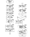
次に、ROM61に格納されている往復記録位置自動調整制御の制御プログラムについて、図4、図5および図6のフローチャートに基づいて説明する。但し、この場合、ROM61には、図7(a)に示す往路記録の為に縦罫線を所定小ピッチで並べた往路記録用縦罫線データと、図7(b)に示す復路記録の為に縦罫線を所定小ピッチで並べた復路記録用縦罫線データとが格納されているとともに、表1に示すように、7種類の検査パターン番号の各々について、復路記録を行うに際して、各記録位置の「ずらし量」が、ドット数にて格納されている。
Next, a control program for reciprocal recording position automatic adjustment control stored in the

ここで、往路記録用縦罫線データは、例えば、図7(a)に示すように、F1〜F2,F7〜F8,F13〜F14,F19〜F20により、2ドット列の縦罫線を4本記録し、続けてF25〜F28,F31〜F34,F37〜F40,F43〜F46により、4ドット列の縦罫線を4本記録するものである。そして、復路記録用縦罫線データは、例えば、図7(b)に示すように、R3〜R4,R9〜R10,R15〜R16,R21〜R22により、F1〜F2,F7〜F8,F13〜F14,F19〜F20に追加的に、2ドット列の縦罫線を2本ずつ記録するものである。 Here, for example, as shown in FIG. 7A, the forward-recording vertical ruled line data records four 2-dot vertical ruled lines by F1 to F2, F7 to F8, F13 to F14, and F19 to F20. Subsequently, four vertical ruled lines of four dot rows are recorded by F25 to F28, F31 to F34, F37 to F40, and F43 to F46. Then, for example, as shown in FIG. 7B, the return rule vertical ruled line data is F1-F2, F7-F8, F13-F14 by R3-R4, R9-R10, R15-R16, R21-R22. , F19 to F20, two vertical ruled lines of 2 dot rows are recorded two by two.
インクジェットプリンタ4を出荷する前の記録検査において、検査者がこのインクジェットプリンタ4の操作パネル65に設けられた往復記録位置補正キーを操作すると、図4に示す制御処理(以下、往復記録位置自動調整制御処理ともいう)が実行される。この往復記録位置補正キーは、複数の既存のキーの組み合わせで構成されていてもよい。この制御が開始されると、先ず、液晶ディスプレイ66に、メッセージ「用紙をセットして下さい」が表示されるので(S100(Sはステップを表す。以下同様。))、検査者は給紙装置2に検査用の用紙をセットする。次に、検査者が検査パターン記録キーを操作した場合(S110:YES)、先ず、記録解像度として600dpiモードを設定する600モードフラグ(600MF)に「1」がセットされる(S120:YES)。
When the inspector operates the reciprocal recording position correction key provided on the
そして、メディアセンサ27により用紙の給紙が確認された場合、即ち、用紙の先端部又は用紙の存在が検出された場合(S130:YES)、検査パターン番号Nに初期値「0」がセットされ(S140)、先ず検査パターン番号「0」のずらし量がドット数で読み込まれる(S150)。次に、往路記録用縦罫線データに基づいて往路記録を実行するとともに、復路記録用縦罫線データとずらし量とに基づいて、用紙送りしないで同一ライン上に復路記録を実行する、検査パターン記録が実行される(S160)。次に、記録された検査パターンの上方をメディアセンサ27に連続的に走査させて(S170)、記録された検査パターンの縦罫線画像を読み込む(S180)。
When the
このとき、検査パターンの記録は、用紙の搬送方向において、メディアセンサ27の位置よりも上流側に位置するノズル(記録ヘッド23Pのノズル)のみによって実行されるので、検査パターンの記録後すぐに走査することができる。したがって、用紙上に検査パターンを全て記録した後、その用紙を別の読み取り装置(スキャナなど)によって読み取る場合に比べて、手間を省くことができる。
At this time, since the recording of the inspection pattern is executed only by the nozzles (nozzles of the
この場合、メディアセンサ27の走査により読み込まれた画像データ、つまり濃淡に関する階調データ(濃度データともいう)について、縦罫線の記録箇所に相当する黒い部分については値が小さくなっており、縦罫線の非記録箇所に相当する白い部分については値が大きくなっている。次に、メディアセンサ27で読み込まれた階調データであるアナログデータがデジタルデータに変換され、そのデジタルデータ、所謂AD値がRAM62のAD値メモリに記憶される(S190)。そして、所定量の用紙送りが実行される(S200)。
In this case, in the image data read by the scanning of the
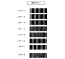
次に、検査パターン番号NがMAX、つまり本実施の形態の場合の最大の番号6でない場合には(S210:NO)、検査パターン番号Nが1つインクリメントされ(S220)、S150〜S220が繰り返して実行される。例えば、図8に示すように、600dpiの解像度であって、復路記録の際に−12ドット、−8ドット、−4ドット、0ドット、+4ドット、+8ドット、+12ドットを夫々ずらした7種類の検査パターンが記録される。 Next, when the inspection pattern number N is MAX, that is, not the maximum number 6 in the present embodiment (S210: NO), the inspection pattern number N is incremented by 1 (S220), and S150 to S220 are repeated. Executed. For example, as shown in FIG. 8, the resolution is 600 dpi, and seven types are shifted by -12 dots, -8 dots, -4 dots, 0 dots, +4 dots, +8 dots, and +12 dots at the time of backward printing. The inspection pattern is recorded.
例えば、ずらし量が「−12ドット」である検査パターンに関しては、図9に示すように、所謂256段階の階調データ(アナログデータ)が微小測定距離毎に求められ、図10に示すように、その階調データについてデジタル数値に変換したデジタルデータ(AD値)が求められ、RAM62のAD値メモリに夫々記憶される。
For example, for an inspection pattern with a shift amount of “−12 dots”, as shown in FIG. 9, so-called 256-step gradation data (analog data) is obtained for each minute measurement distance, as shown in FIG. Then, digital data (AD value) obtained by converting the gradation data into a digital numerical value is obtained and stored in the AD value memory of the
また、ずらし量が「0ドット」である検査パターンに関しては、図11に示すように、256段階の階調データ(アナログデータ)が微小測定距離毎に求められ、図12に示すように、その階調データについてデジタル数値に変換したAD値がRAM62のAD値メモリに夫々記憶される。
As for the inspection pattern with the shift amount of “0 dot”, as shown in FIG. 11, 256-step gradation data (analog data) is obtained for each minute measurement distance, and as shown in FIG. AD values converted into digital numerical values for the gradation data are respectively stored in the AD value memory of the
次に、検査パターン番号Nが最大値(MAX)6の場合には(S210:YES)、全ての検査パターン記録が終了したので、これら7種類のうちから最良の検査パターン番号Nを検出する演算処理(以下、最良検査パターン番号N演算処理ともいう。図5参照)が実行される(S230)。 Next, when the inspection pattern number N is the maximum value (MAX) 6 (S210: YES), since all inspection pattern recording has been completed, the calculation for detecting the best inspection pattern number N from these seven types. Processing (hereinafter, also referred to as best inspection pattern number N calculation processing, see FIG. 5) is executed (S230).
最良の検査パターン番号Nを検出する演算処理が開始されると、まず、カウンタmに0を設定して、カウンタmの初期化を行う(S310)。次に、検査パターンのAD値(デジタルデータ)に基づき、最良の検査パターン番号Nを判定するための判定用データを検出する演算処理(以下、判定用データ演算処理ともいう。図6参照)が実行される(S320)。 When the calculation process for detecting the best inspection pattern number N is started, first, the counter m is set to 0 and the counter m is initialized (S310). Next, based on the AD value (digital data) of the test pattern, a calculation process for detecting determination data for determining the best test pattern number N (hereinafter also referred to as a determination data calculation process; see FIG. 6). It is executed (S320).
判定用データの演算処理が開始されると、まず、検査パターン番号Nの検出パターンにおけるパターン繰り返し数Pを取得する(S510)。なお、パターン繰り返し数Pは、図7(a)に示す往路記録用縦罫線データと、図7(b)に示す復路記録用縦罫線データとが重ね合わせて記録される検査パターンの繰り返し回数であり、ROM61に格納されている。
When the calculation processing of the determination data is started, first, the pattern repetition number P in the detection pattern with the inspection pattern number N is acquired (S510). Note that the pattern repetition number P is the number of repetitions of the inspection pattern recorded by superimposing the forward recording vertical ruled line data shown in FIG. 7A and the backward recording vertical ruled line data shown in FIG. 7B. Yes, stored in
次に、検査パターンのAD値(デジタルデータ)の全データ個数n(全ドット数)を取得し(S520)、全データ個数nをパターン繰り返し数Pで除算して、AD値(デジタルデータ)におけるパターン間隔Kを算出する(S530)。 Next, the total number of data n (total number of dots) of the AD value (digital data) of the inspection pattern is acquired (S520), and the total number of data n is divided by the pattern repetition number P to obtain the AD value (digital data). The pattern interval K is calculated (S530).
続いて、部分データのカウンタiに1を設定して、カウンタiの初期化を行い(S540)、部分データの先頭アドレスtに1を設定して、先頭アドレスtの初期化を行う(S550)。 Subsequently, the counter i of the partial data is set to 1 and the counter i is initialized (S540), and the start address t of the partial data is set to 1 and the start address t is initialized (S550). .
次に、AD値(デジタルデータ)のうち先頭アドレスtからパターン間隔Kまでの部分データを抽出し(S560)、抽出した部分データのうちの最大値Liと最小値Siを検出する(S570)。そして、検出した最大値Liと最小値Siとの差分の絶対値を部分データの振幅Aiとして算出し(S580)、算出した振幅Aiをi番目の部分データにおける濃度振幅値BiとしてRAM62に記憶する(S590)。
Next, partial data from the start address t to the pattern interval K is extracted from the AD value (digital data) (S560), and the maximum value Li and the minimum value Si are detected from the extracted partial data (S570). Then, the absolute value of the difference between the detected maximum value Li and minimum value Si is calculated as the amplitude Ai of the partial data (S580), and the calculated amplitude Ai is stored in the
次に、カウンタiが1つインクリメントされ(S600)、カウンタiが2Pに等しくない場合(換言すれば、パターン繰り返し数Pの2倍の値と同じ値でない場合)には(S610:NO)、部分データの先頭アドレスtを部分検知間隔(K/2)だけ進めて(S620)、再びS560に移行する。そして、カウンタiが2Pに等しくない期間中は(S610:NO)、S560〜S620の処理が繰り返し実行される。 Next, when the counter i is incremented by 1 (S600) and the counter i is not equal to 2P (in other words, when it is not the same value as twice the number of pattern repetitions P) (S610: NO), The head address t of the partial data is advanced by the partial detection interval (K / 2) (S620), and the process proceeds to S560 again. Then, while the counter i is not equal to 2P (S610: NO), the processing of S560 to S620 is repeatedly executed.
この繰り返し処理により、検査パターンの一端部から他端部にわたり、AD値(デジタルデータ)から、部分検知間隔(K/2)ごとに部分判定区間(幅寸法がパターン間隔K)に含まれる部分データを複数回(本実施形態では、(2P−1)回)にわたり抽出し、各部分判定区間について、部分データの最小値Siと最大値Liとの差分を濃度振幅値Biとして検出することが出来る。 By this repeated processing, partial data included in the partial determination section (width dimension is pattern interval K) from the AD value (digital data) for each partial detection interval (K / 2) from one end to the other end of the inspection pattern. Can be extracted multiple times (in this embodiment, (2P-1) times), and for each partial determination section, the difference between the minimum value Si and the maximum value Li of the partial data can be detected as the concentration amplitude value Bi. .
そして、カウンタiが2Pに等しくなると(S610:YES)、複数の部分データのうち互いに隣接する部分データ同士の濃度振幅値Biの差分を算出し、算出結果を振幅差分値Cj(=Bj+1−Bj)として検出する(S630)。なお、濃度振幅値Biは、(2P−1)個検出されているため、振幅差分値Cjは、(2P−2)個検出される。 When the counter i becomes equal to 2P (S610: YES), the difference between the density amplitude values Bi of the partial data adjacent to each other among the plurality of partial data is calculated, and the calculation result is expressed as the amplitude difference value Cj (= Bj + 1). -Bj) (S630). Since (2P-1) density amplitude values Bi are detected, (2P-2) amplitude difference values Cj are detected.
続いて、(2P−2)個の振幅差分値Cjのうちの最大値(振幅差分最大値)を検出し、検出した振幅差分最大値を、カウンタmの検査パターンにおける判定用データに設定する(S640)。 Subsequently, the maximum value (amplitude difference maximum value) of the (2P-2) amplitude difference values Cj is detected, and the detected amplitude difference maximum value is set as determination data in the inspection pattern of the counter m ( S640).
S640での処理が終了して判定用データ演算処理が完了すると、再び、最良の検査パターン番号N演算処理に処理が移行し、カウンタmが検査パターン番号のMAX、つまり本実施の形態の場合の最大の番号6でない場合には(S330:NO)、カウンタmが1つインクリメントされ(S340)、S320〜S340が繰り返し実行される。 When the processing in S640 is completed and the determination data calculation process is completed, the process again proceeds to the best test pattern number N calculation process, and the counter m is the test pattern number MAX, that is, in the case of the present embodiment. If it is not the maximum number 6 (S330: NO), the counter m is incremented by 1 (S340), and S320 to S340 are repeatedly executed.
この繰り返し処理により、全て(本実施形態では、7種類)の検査パターンのそれぞれについて、(2P−2)個の振幅差分値Cjが検出されるとともに、(2P−2)個の振幅差分値Cjのうちの最大値(振幅差分最大値)が、それそれの検査パターンにおける判定用データとして設定される。 By this iterative process, (2P-2) amplitude difference values Cj are detected and (2P-2) amplitude difference values Cj are detected for all (seven types in this embodiment) inspection patterns. The maximum value (amplitude difference maximum value) is set as determination data in each inspection pattern.
このようにして設定された判定用データD0〜D6は、表2に示すように、RAM62の判定用データメモリに夫々記憶される。
The determination data D0 to D6 set in this way are stored in the determination data memory of the
次に、全ての検査パターンについて、判定用データDx(0≦x≦6)に基づき比較を行い、全ての検査パターンの中から、判定用データDxが最小となる検査パターンを検出して、その検査パターンを最良の検査パターンと判定する(S350)。 Next, all the inspection patterns are compared based on the determination data Dx (0 ≦ x ≦ 6), and the inspection pattern having the minimum determination data Dx is detected from all the inspection patterns. The inspection pattern is determined as the best inspection pattern (S350).
なお、本実施形態においては、全ての検査パターンのうち、階調データ(アナログデータ)の変化が少なく、AD値(デジタルデータ)から検出した複数の振幅差分値Cjのうちの最大値(振幅差分最大値)である判定用データDxが最も小さい、検査パターン番号N=3のずらし量「0」が最良であると判定される。 In the present embodiment, the gradation data (analog data) changes little among all the inspection patterns, and the maximum value (amplitude difference) among the plurality of amplitude difference values Cj detected from the AD value (digital data). It is determined that the shift amount “0” of the inspection pattern number N = 3 having the smallest determination data Dx which is the maximum value is the best.
S350での処理が終了して最良検査パターン番号N演算処理が完了すると、再び、往復記録位置自動補正制御に処理が移行し、600モードフラグ(600MF)に「1」がセットされているか否かを判断する(S240)。そして、600モードフラグ(600MF)に「1」がセットされている場合には(S240:YES)、600dpiの解像度として最良の検査パターン番号N(=3)がRAM62に記憶されるとともに、最良検査パターンと判定された検査パターン番号Nのずらし量が、600dpiの解像度で記録を行う際の記録位置として設定される(S250)。
When the process in S350 is completed and the best inspection pattern number N calculation process is completed, the process again shifts to the reciprocal recording position automatic correction control, and whether or not “1” is set in the 600 mode flag (600MF). Is determined (S240). If “1” is set in the 600 mode flag (600MF) (S240: YES), the best inspection pattern number N (= 3) is stored in the
次に、その最良の検査パターン番号N(=3)に対応するずらしドット数と、その縦罫線とが記録される(S260)。本実施形態においては、図8に示すように、用紙には、ずらし量を異ならせた7種類の検査パターンに加えて、600dpiの解像度として最良の検査パターン番号「3」に対応する、ずらしドット数「0」と、その検査パターンとが再び記録される。 Next, the number of shifted dots corresponding to the best inspection pattern number N (= 3) and the vertical ruled line are recorded (S260). In this embodiment, as shown in FIG. 8, in addition to the seven types of inspection patterns with different shift amounts, the paper includes a shifted dot corresponding to the best inspection pattern number “3” with a resolution of 600 dpi. The number “0” and the inspection pattern are recorded again.
そして、600モードフラグ(600MF)がリセット、即ち「0」クリアされる(S270)。
なお、本実施の形態においては、解像度モードとして600モードまたは1200モードのいずれかを選択可能に構成されており、600モードフラグ(600MF)がリセットされることで、1200モードが設定される。
Then, the 600 mode flag (600MF) is reset, that is, cleared to “0” (S270).
In the present embodiment, either the 600 mode or the 1200 mode can be selected as the resolution mode, and the 1200 mode is set by resetting the 600 mode flag (600 MF).
S270での処理により600モードフラグ(600MF)がリセットされて、1200モードが設定されると、1200dpiの解像度に基づいて、S150以降の処理が、上述した内容と同様に繰り返し実行される。即ち、1200dpiの解像度において、図7の往路記録用及び復路記録用縦罫線データに基づいて、7種類の検査パターンが記録(図13参照)される(S150〜S220)。 When the 600 mode flag (600MF) is reset by the processing in S270 and the 1200 mode is set, the processing after S150 is repeatedly executed in the same manner as described above based on the resolution of 1200 dpi. That is, at a resolution of 1200 dpi, seven types of inspection patterns are recorded (see FIG. 13) based on the forward and backward recording vertical ruled line data shown in FIG. 7 (S150 to S220).
なお、解像度モードが3つ以上ある場合には、(その解像度モードの数−1)の数のフラグを持たせるように構成してもよい。
そして、各検査パターンについて、AD値(デジタルデータ)から複数の振幅差分値Cjを検出し、検出した複数の振幅差分値Cjのうちの最大値(振幅差分最大値)を判定用データDxとして設定し、判定用データDxが最も小さい検査パターンを判定して、その検査パターンを最良の検査パターンと判定する(S230)。
When there are three or more resolution modes, the number of flags (number of resolution modes-1) may be provided.
For each inspection pattern, a plurality of amplitude difference values Cj are detected from the AD value (digital data), and the maximum value (amplitude difference maximum value) among the detected plurality of amplitude difference values Cj is set as determination data Dx. Then, the inspection pattern having the smallest determination data Dx is determined, and the inspection pattern is determined as the best inspection pattern (S230).
なお、本実施形態の1200dpiモードにおいては、図13に示す7種類の検査パターンのうち、階調データ(アナログデータ)の変化が少なく、AD値(デジタルデータ)から検出した複数の振幅差分値Cjのうちの最大値(振幅差分最大値)である判定用データDxが最も小さい、検査パターン番号N=4のずらし量「+4」が最良であると判定される。 In the 1200 dpi mode of the present embodiment, among the seven types of inspection patterns shown in FIG. 13, there are few changes in gradation data (analog data), and a plurality of amplitude difference values Cj detected from AD values (digital data). It is determined that the shift amount “+4” of the inspection pattern number N = 4 having the smallest determination data Dx that is the maximum value (amplitude difference maximum value) is the best.
そのあと、S240にて否定判定されると(S240:NO)、1200dpiの解像度として最良の検査パターン番号N(N=4)がRAM62に記憶されるとともに、最良検査パターンと判定された検査パターン番号Nのずらし量が、1200dpiの解像度で記録を行う際の記録位置として設定される(S280)。そして、最良検査パターンと判定された検査パターン番号Nのずらしドット数「+4」と、その検査パターンとが記録(図13参照)される(S290)。
Thereafter, when a negative determination is made in S240 (S240: NO), the best inspection pattern number N (N = 4) is stored in the
このように、往路記録に対する復路記録のずらしドット数を複数段階に切換えた複数の検査パターンが記録され、その記録された複数の検査パターンがメディアセンサ27によるライン状の走査により連続的に読み取られて解析されるので、複数の検査パターンのうちの何れかが最良の検査パターンとして自動的に選出することができる。
In this way, a plurality of inspection patterns in which the number of shifted dots in the backward recording with respect to the outward recording is switched to a plurality of stages are recorded, and the plurality of recorded inspection patterns are continuously read by line-like scanning by the
更に、その選出された最良の検査パターンとそのずらしドット数とが用紙に再び記録されるので、検査者はその記録された検査パターン、つまり記録制御で最適な検査パターンとして認識した検査パターンが最良であるか否かを目視で確認することができる。 Further, the selected best inspection pattern and the number of shifted dots are recorded on the paper again, so that the inspector finds the recorded inspection pattern, that is, the inspection pattern recognized as the optimum inspection pattern by the recording control. It can be visually confirmed whether or not.
以上説明したように、本実施形態においては、検査パターンのAD値(デジタルデータ)の最大値・最小値に基づき、AD値の変化量が最小となる最良検査パターンを判定するのではなく、AD値(濃度データ)のうち部分判定区間どうしの濃度振幅値の差分(振幅差分値Cj)に基づき、複数の検査パターンの中から最良検査パターンを判定している。 As described above, in the present embodiment, based on the maximum value / minimum value of the AD value (digital data) of the inspection pattern, the best inspection pattern that minimizes the change amount of the AD value is not determined. The best test pattern is determined from a plurality of test patterns based on the difference (amplitude difference value Cj) between the density amplitude values of the partial determination sections among the values (density data).
そして、AD値の振幅差分値Cjは、AD値の変化量が反映された値を示すことから、振幅差分値Cjに基づいてAD値の変化量が小さいと判断できる検査パターンは、記録位置ズレが生じていないと判定できる。 Since the amplitude difference value Cj of the AD value indicates a value reflecting the amount of change in the AD value, a test pattern that can be determined that the amount of change in the AD value is small based on the amplitude difference value Cj It can be determined that no has occurred.
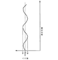
ここで、図14に、濃度データ(AD値)の波形全体における最大値と最小値との差分値Hが大きいが、濃度データが緩やかに変化する検査パターンの濃度データ波形(波形1)と、波形1の差分値Hに比べて最大値と最小値との差分値H’は小さいが、濃度データが不規則に変化する検査パターンの濃度データ波形(波形2)と、を示す。
Here, FIG. 14 shows a density data waveform (waveform 1) of a test pattern in which the difference value H between the maximum value and the minimum value in the entire waveform of the density data (AD value) is large, but the density data changes slowly. The difference value H ′ between the maximum value and the minimum value is smaller than the difference value H of the
そして、図14では、波形1の下側に、波形1における部分判定区間T1〜T7の設定位置を示しており、また、部分判定区間T1〜T7における振幅Ai(濃度振幅値Bi)および振幅差分値Cjの数値例が記載された表を示している。
In FIG. 14, the setting positions of the partial determination sections T1 to T7 in the
この表における6個の振幅差分値Cjのうち最大値は、第6番目の振幅差分値C6(=48)であり、振幅差分値C6の値が判定用データとして設定される。
なお、本実施形態においては、波形のAD値(デジタルデータ)を256段階の数値データとしてメモリに記憶している。このAD値(デジタルデータ)のデータ形式は、256段階の数値データに限られることはなく、例えば、高い分解能が必要となる場合には、AD値を段階数の多い数値データ(1024段階の数値データなど)として記憶すると良い。
The maximum value among the six amplitude difference values Cj in this table is the sixth amplitude difference value C6 (= 48), and the value of the amplitude difference value C6 is set as determination data.
In the present embodiment, the AD value (digital data) of the waveform is stored in the memory as numerical data of 256 levels. The data format of the AD value (digital data) is not limited to 256-step numerical data. For example, when high resolution is required, the AD value is converted into numerical data with a large number of steps (1024 numerical values). Data, etc.).
ところで、図14における波形1および波形2について、人間の目視判定による判定結果を比較した場合、波形1は、濃度データが緩やかに変化するため、人間の目視判定では、記録ムラがあると感じにくく記録位置ズレが無いと判定できるが、波形2は、濃度データが不規則に変化するため、人間の目視判定では、記録ムラがあると感じられて記録位置ズレが生じていると判定できる。
By the way, when the judgment result by the human visual judgment is compared with respect to the
そして、波形1および波形2ついて、上記の実施形態の多機能装置1を用いて記録位置ズレの有無を判定した場合、波形1は、振幅差分値Cjが全体的に小さい値となり、判定用データDxに小さい値が設定されるのに対して、波形2は、振幅差分値Cjが大きい値となり、判定用データDxに大きい値が設定される。このため、判定用データが大きい波形2は、AD値の変化量が大きく記録位置ズレが生じていると判断でき、判定用データが小さい波形1は、AD値の変化量が小さく記録位置ズレが生じていないと判断できる。
When the presence or absence of the recording position deviation is determined for the
そして、全ての検査パターンのうち、波形1の判定用データが最小値となる場合には、波形1の検査パターンが最良の検査パターンと判定される。
なお、AD値(濃度データ)の最大値・最小値に基づき、濃度データの最大値と最小値との差分(ピーク差分値)が最小となる最良検査パターンを判定する従来の判定方法においては、濃度データの連続性を考慮することなく離散的な濃度データに基づいて、記録位置ズレを判定している。
When the determination data for
In the conventional determination method for determining the best inspection pattern that minimizes the difference (peak difference value) between the maximum value and the minimum value of the density data based on the maximum value / minimum value of the AD value (density data), The recording position deviation is determined based on discrete density data without considering the continuity of density data.
これに対して、本実施形態のように、濃度データの振幅差分値Cjに基づいて判定する場合には、濃度データの連続性を考慮しつつ記録位置ズレを判定できるため、濃度データの最大値と最小値との差が大きい検査パターンであっても、濃度データが全体的に緩やかに変化する場合には、最良検査パターンとして判定できる。 On the other hand, when the determination is made based on the amplitude difference value Cj of the density data as in the present embodiment, the recording position deviation can be determined in consideration of the continuity of the density data. Even if the test pattern has a large difference between the minimum value and the minimum value, it can be determined as the best test pattern if the density data changes gradually as a whole.
また、上記の実施形態においては、検査パターンの全領域において振幅差分値Cjを検出することから、振幅差分値Cjの全体的な変化状態を把握できると共に、濃度データの全体的な変化状態を把握することができる。 In the above embodiment, since the amplitude difference value Cj is detected in the entire region of the inspection pattern, it is possible to grasp the overall change state of the amplitude difference value Cj and grasp the overall change state of the density data. can do.
そして、複数の振幅差分値Cjのうち最大値となる振幅差分最大値は、その検査パターンにおける濃度データの変化量のうちの最大値(変化量最大値)に比例した値を示すと共に、その検査パターンにおける記録位置ズレのうち最も大きいズレ量(記録位置ズレ量最大値)に比例した値を示す。このため、全ての検査パターンの中から、振幅差分最大値が最も小さい検査パターンを判定することで、最も記録位置ズレが小さい検査パターンを抽出できる。 The maximum amplitude difference value among the plurality of amplitude difference values Cj indicates a value proportional to the maximum value (change amount maximum value) of the change amounts of the density data in the inspection pattern, and the inspection. The value is proportional to the largest deviation amount (maximum recording position deviation amount) among the recording position deviations in the pattern. For this reason, the inspection pattern with the smallest recording position shift can be extracted by determining the inspection pattern having the smallest amplitude difference maximum value from all the inspection patterns.
よって、本実施形態によれば、濃度データの全体的な変化状態を把握できると共に、最も記録位置ズレが小さい検査パターンを抽出できることから、検査パターンの濃度データが全体的に緩やかに変化する検査パターンであっても、最良検査パターンとして判定でき、人間の感覚に近い判定結果を得ることができる。 Therefore, according to the present embodiment, since the overall change state of the density data can be grasped and the test pattern having the smallest recording position deviation can be extracted, the test pattern in which the density data of the test pattern changes slowly as a whole. Even so, it can be determined as the best test pattern, and a determination result close to a human sense can be obtained.
なお、本実施形態においては、インクジェットプリンタ4が特許請求の範囲に記載の記録装置に相当し、記録ヘッド23Pが記録ヘッドに相当し、記録機構部10が記録手段に相当し、往復記録位置自動調整制御処理におけるS160での処理が検査パターン記録手段に相当し、メディアセンサ27がセンサに相当し、S170、S180およびS190での処理が濃度データ検出手段に相当する。
In this embodiment, the
また、階調データ(アナログデータ)またはAD値(デジタルデータ)が濃度データに相当し、判定用データ演算処理におけるS510からS620までの処理が濃度振幅検出手段に相当し、S630での処理が振幅差分検出手段に相当し、判定用データ演算処理におけるS640および最良検査パターン番号N演算処理におけるS350が最良パターン判定手段に相当し、往復記録位置自動調整制御処理におけるS250およびS280での処理が記録位置設定手段に相当する。 Further, the gradation data (analog data) or AD value (digital data) corresponds to the density data, the processing from S510 to S620 in the determination data calculation processing corresponds to the density amplitude detecting means, and the processing in S630 is the amplitude. S640 in the determination data calculation process and S350 in the best inspection pattern number N calculation process correspond to the best pattern determination means, and the processes in S250 and S280 in the reciprocal recording position automatic adjustment control process correspond to the difference detection means. This corresponds to setting means.
さらに、往復記録位置自動調整制御処理による往復記録位置調整方法が特許請求の範囲に記載の往復記録位置調整方法に相当し、往復記録位置自動調整制御処理におけるS160での処理が第1工程に相当し、S170、S180およびS190での処理が第2工程に相当し、判定用データ演算処理におけるS510からS620までの処理が第3工程に相当し、S630での処理が第4工程に相当し、判定用データ演算処理におけるS640および最良検査パターン番号N演算処理におけるS350が第5工程に相当し、往復記録位置自動調整制御処理におけるS250およびS280での処理が第6工程に相当する。 Further, the reciprocating recording position adjusting method by the reciprocating recording position automatic adjustment control process corresponds to the reciprocating recording position adjusting method described in the claims, and the process in S160 in the reciprocating recording position automatic adjustment control process corresponds to the first step. In S170, S180 and S190, the process from S510 to S620 in the determination data calculation process corresponds to the third process, and the process in S630 corresponds to the fourth process. S640 in the determination data calculation process and S350 in the best inspection pattern number N calculation process correspond to the fifth process, and the processes in S250 and S280 in the reciprocal recording position automatic adjustment control process correspond to the sixth process.
以上、本発明の一実施形態について説明したが、本発明は、上記実施形態に限定されることなく、種々の態様をとることができる。
上記の実施形態(以下、第1実施形態という)においては、判定用データ演算処理のS640において、全ての振幅差分値Cjのうちの最大値(振幅差分最大値)を判定用データとして設定しているが、判定用データとして設定するための数値は、振幅差分最大値に限られることはない。
As mentioned above, although one Embodiment of this invention was described, this invention can take a various aspect, without being limited to the said embodiment.
In the above embodiment (hereinafter referred to as the first embodiment), in S640 of the determination data calculation process, the maximum value (amplitude difference maximum value) of all the amplitude difference values Cj is set as the determination data. However, the numerical value to be set as the determination data is not limited to the maximum amplitude difference value.
例えば、振幅差分最大値に代えて、全ての振幅差分値Cjの平均値(全体振幅差分平均値)を判定用データとして設定してもよい。そして、全体振幅差分平均値が設定された判定用データに基づき、全ての検査パターンのうち、判定用データが最小となる検査パターンを最良検査パターンと判定するのである(第2実施形態)。 For example, instead of the maximum amplitude difference value, an average value (overall amplitude difference average value) of all amplitude difference values Cj may be set as the determination data. Then, based on the determination data in which the overall amplitude difference average value is set, the inspection pattern having the minimum determination data among all the inspection patterns is determined as the best inspection pattern (second embodiment).
ここで、全体振幅差分平均値は、濃度データにノイズ等の影響による変動が生じた場合であっても、その変動の程度が小さい場合には、ノイズ等が無い時の全体振幅差分平均値と比べて、値が大きく変化することはない。つまり、濃度データが全体として緩やかに変化する検査パターンにおいては、ノイズなどの影響が小さい場合には、全体振幅差分平均値は小さい値を示す。 Here, even if the average amplitude difference average value is a fluctuation due to the influence of noise or the like in the density data, if the degree of the fluctuation is small, the total amplitude difference average value when there is no noise or the like In comparison, the value does not change significantly. That is, in the test pattern in which the density data changes slowly as a whole, the average value of the overall amplitude difference shows a small value when the influence of noise or the like is small.
このように、濃度データが全体として緩やかに変化すると共にノイズなどの影響による変動が小さい検査パターンは、人間の目視判定においては、記録位置ズレが生じていないと判定できる。このため、全体振幅差分平均値に基づいて複数の検査パターンを判定することで、記録位置ズレが少ない最良な検査パターンを判定するにあたり、人間の判定結果に近い判定結果を得ることができる。 As described above, the inspection pattern in which the density data changes gently as a whole and the fluctuation due to the influence of noise or the like is small can be determined that there is no recording position deviation in human visual determination. For this reason, by determining a plurality of inspection patterns based on the overall amplitude difference average value, it is possible to obtain a determination result close to a human determination result in determining the best inspection pattern with little recording position deviation.
なお、ノイズなどの影響による濃度データの変動の程度が大きい場合には、ノイズ等が無い場合と比べて、振幅差分値Cjは全体的に大きい値となり、ノイズなどの影響を大きく受けた検査パターンは、全体振幅差分平均値が大きい値を示す。 Note that when the degree of variation in density data due to the influence of noise or the like is large, the amplitude difference value Cj becomes a large value as a whole compared to the case where there is no noise or the like, and the inspection pattern greatly affected by the noise or the like. Indicates a large overall amplitude difference average value.
そして、このようなノイズなどの影響による変動が大きい検査パターンは、人間の目視判定においては、記録位置ズレが生じていると判定できる。このため、全体振幅差分平均値としての判定用データが最小となる検査パターンを最良の検査パターンと判定することにより、記録位置ズレが生じている不良な検査パターンを最良な検査パターンであると誤って判定するのを避けることができる。 Further, it is possible to determine that a recording position shift has occurred in an inspection pattern having a large variation due to the influence of noise or the like in human visual determination. For this reason, by determining the inspection pattern having the smallest determination data as the overall amplitude difference average value as the best inspection pattern, a defective inspection pattern in which a recording position shift occurs is erroneously determined as the best inspection pattern. Can be avoided.
よって、第2実施形態のように、全体振幅差分平均値に基づき判定を行うことで、突発的なノイズなどの影響を抑えつつ最良な検査パターンを判定できると共に、多大なノイズなどの影響を受けた不良な検査パターンを誤って最良な検査パターンと判定するのを防ぐことができ、人間の感覚に近い判定結果を得ることができる。 Therefore, as in the second embodiment, by making a determination based on the overall amplitude difference average value, it is possible to determine the best inspection pattern while suppressing the influence of sudden noise and the like, and the influence of a large amount of noise and the like. Therefore, it is possible to prevent a defective inspection pattern from being erroneously determined as the best inspection pattern, and to obtain a determination result that is close to a human sense.
また、判定用データは、振幅差分最大値または全体振幅差分平均値に代えて、振幅差分値Cjの最小昇順振幅差分平均値を設定しても良い。なお、振幅差分値Cjの最小昇順振幅差分平均値は、全ての振幅差分値Cjを昇順に並べて、最小値から検出対象個数までの振幅差分値Cjを抽出し、抽出した検出対象個数の振幅差分値Cjの平均値として得られる値である。 The determination data may be set to the minimum ascending order amplitude difference average value of the amplitude difference value Cj instead of the maximum amplitude difference value or the overall amplitude difference average value. The minimum ascending order amplitude difference average value of the amplitude difference values Cj is obtained by arranging all the amplitude difference values Cj in ascending order, extracting the amplitude difference value Cj from the minimum value to the number of detection targets, and extracting the amplitude difference of the number of detection targets extracted. This is a value obtained as an average value of the values Cj.
そして、最小昇順振幅差分平均値が設定された判定用データに基づき、全ての検査パターンのうち、判定用データが最小となる検査パターンを最良検査パターンと判定するのである(第3実施形態)。 Based on the determination data in which the minimum ascending order amplitude difference average value is set, the inspection pattern having the minimum determination data among all the inspection patterns is determined as the best inspection pattern (third embodiment).
ここで、濃度データにノイズ等の影響による変動が生じた場合、その変動が生じた部分の振幅差分値Cjは大きな値となるため、昇順に並べられた振幅差分値Cjのうち最小値から検出対象個数までの振幅差分値Cjの中に、ノイズなどの影響を受けた振幅差分値が含まれる可能性はきわめて低くなる。 Here, when a variation due to the influence of noise or the like occurs in the density data, the amplitude difference value Cj of the portion where the variation has occurred becomes a large value, and therefore it is detected from the minimum value among the amplitude difference values Cj arranged in ascending order. The possibility that an amplitude difference value affected by noise or the like is included in the amplitude difference values Cj up to the target number is extremely low.
そのため、最小昇順振幅差分平均値は、濃度データにノイズ等の影響による変動が生じた場合であっても、ノイズ等が無い時の最小昇順振幅差分平均値と比べて、値が大きく変化することはない。つまり、濃度データが全体として緩やかに変化する検査パターンにおいては、濃度データにノイズなどの影響による変動が生じた場合であっても、ノイズなどの発生頻度が少ない場合には、最小昇順振幅差分平均値は小さい値を示す。 Therefore, the minimum ascending amplitude difference average value varies greatly compared to the minimum ascending amplitude difference average value when there is no noise, etc., even when the density data fluctuates due to the influence of noise or the like. There is no. In other words, in an inspection pattern in which density data changes slowly as a whole, the minimum ascending amplitude difference average is used when the frequency of occurrence of noise is low, even if the density data fluctuates due to the influence of noise or the like. The value indicates a small value.
このように、濃度データが全体として緩やかに変化すると共にノイズなどの発生頻度が少ない検査パターンは、人間の目視判定においては、記録位置ズレが生じていないと判定できる。このため、最小昇順振幅差分平均値に基づいて、複数の検査パターンのうち最小昇順振幅差分平均値(判定データ)が最小となる検査パターンを最良の検査パターンと判定することで、人間の感覚に近い判定結果を得ることができる。 As described above, the inspection pattern in which the density data changes gradually as a whole and the frequency of occurrence of noise or the like is low can be determined as having no recording position deviation in human visual determination. For this reason, based on the minimum ascending order amplitude difference average value, by determining the inspection pattern having the minimum minimum ascending order amplitude difference average value (determination data) among the plurality of inspection patterns as the best inspection pattern, A close determination result can be obtained.
なお、ノイズなどの影響による濃度データの変動の発生頻度が高い場合には、ノイズ等による変動が無い場合と比べて、複数の振幅差分値のうち大きい値となる振幅差分値の割合が大きくなり、ノイズなどの影響を大きく受けた検査パターンは、最小昇順振幅差分平均値が大きい値を示す。 When the frequency of density data fluctuations due to the influence of noise or the like is high, the ratio of the amplitude difference values that are larger among the plurality of amplitude difference values is larger than when there is no fluctuation due to noises or the like. The inspection pattern that is greatly affected by noise or the like shows a value with a large minimum ascending order amplitude difference average value.
そして、このようなノイズなどの影響による変動が大きい検査パターンは、人間の目視判定においては、記録位置ズレが生じていると判定できる。このため、全体振幅差分平均値としての判定用データが最小となる検査パターンを最良の検査パターンと判定することにより、記録位置ズレが生じている不良な検査パターンを最良な検査パターンであると誤って判定するのを避けることができる。 Further, it is possible to determine that a recording position shift has occurred in an inspection pattern having a large variation due to the influence of noise or the like in human visual determination. For this reason, by determining the inspection pattern having the smallest determination data as the overall amplitude difference average value as the best inspection pattern, a defective inspection pattern in which a recording position shift occurs is erroneously determined as the best inspection pattern. Can be avoided.
よって、最小昇順振幅差分平均値に基づき判定を行うことで、全体的には均一であって、一部にノイズなどの影響による変動部分を有する検査パターンであっても、一部の変動部分による影響を抑えつつ、最良な検査パターンであると判定できる。また、このように判定を行うことで、多大なノイズなどの影響を受けた不良な検査パターンを誤って最良な検査パターンと判定するのを防ぐことができ、人間の感覚に近い判定結果を得ることができる。 Therefore, by performing the determination based on the minimum ascending amplitude difference average value, even if the inspection pattern is uniform overall and has a variation portion due to the influence of noise or the like, it depends on a portion of the variation portion. It can be determined that the test pattern is the best while suppressing the influence. In addition, by performing the determination in this way, it is possible to prevent a defective inspection pattern affected by a large amount of noise from being erroneously determined as the best inspection pattern, and obtain a determination result close to human senses. be able to.
ここで、図15に、ノイズの影響により一部の濃度データ(AD値)の最大値と最小値との差分値H2が大きいが、ノイズ以外の部分は差分値H2よりも小さい差分値H1となって濃度データが緩やかに変化する検査パターンの濃度データ波形(波形3)と、波形3の差分値H2に比べて最大値と最小値との差分値H3は小さいが、濃度データが不規則に変化する検査パターンの濃度データ波形(波形4)と、を示す。 Here, FIG. 15 shows that the difference value H2 between the maximum value and the minimum value of some density data (AD value) is large due to the influence of noise, but the difference value H1 is smaller than the difference value H2 in the part other than noise. The density data waveform (waveform 3) of the inspection pattern in which the density data gradually changes and the difference value H3 between the maximum value and the minimum value is smaller than the difference value H2 of the waveform 3, but the density data is irregular. The density data waveform (waveform 4) of the test pattern which changes is shown.
波形3と波形4とを比較した場合、人間の目視判定では、波形3は、一部にノイズの影響があるものの、全体としては濃度データが緩やかに変化するため、記録位置ズレが無いと判定できるが、波形4は、濃度データが不規則に変化するため、記録ムラがあると感じられて記録位置ズレが生じていると判定できる。
When comparing the waveform 3 and the
そして、波形3および波形4について、検査パターンの濃度データから複数の振幅差分値Cjを検出し、振幅差分値Cjの最小昇順振幅差分平均値を判定用データとして設定する判定方法を用いて記録位置ズレの有無を判定した場合、波形3は、最小昇順振幅差分平均値が小さい値となり、判定用データに小さい値が設定されるのに対して、波形4は、最小昇順振幅差分平均値が大きい値となり、判定用データに大きい値が設定される。
Then, with respect to the waveform 3 and the
このため、判定用データ(最小昇順振幅差分平均値)が大きい波形4は、AD値の変化量が大きく記録位置ズレが生じていると判断でき、判定用データ(最小昇順振幅差分平均値)が小さい波形3は、AD値の変化量が小さく記録位置ズレが生じていないと判断できる。
For this reason, it can be determined that the
そして、全ての検査パターンのうち、波形3の判定用データ(最小昇順振幅差分平均値)が最小値となる場合には、波形3の検査パターンが最良の検査パターンと判定される。
よって、検査パターンの濃度データから複数の振幅差分値Cjを検出し、それらの振幅差分値Cjの最小昇順振幅差分平均値を判定用データとして設定する判定方法においては、記録位置ズレの有無の判定結果が、人間の目視判定による判定結果に近い判定結果となる。
If the determination data (minimum ascending order amplitude difference average value) of the waveform 3 is the minimum value among all the inspection patterns, the inspection pattern of the waveform 3 is determined as the best inspection pattern.
Therefore, in the determination method in which a plurality of amplitude difference values Cj are detected from the density data of the inspection pattern and the minimum ascending order amplitude difference average value of these amplitude difference values Cj is set as determination data, the determination of the presence / absence of a recording position shift is performed. The result is a determination result close to the determination result by human visual determination.
ところで、上記の3つの実施形態においては、検査パターンの一端部から他端部にわたる全領域において、濃度データ(AD値(デジタルデータ))から振幅差分値Cjを検出しているが、検査パターンの一部領域から濃度データの振幅差分値Cjを検出するように構成してもよい。 By the way, in the above three embodiments, the amplitude difference value Cj is detected from the density data (AD value (digital data)) in the entire region extending from one end to the other end of the test pattern. You may comprise so that the amplitude difference value Cj of density data may be detected from a partial area | region.
例えば、上記の実施形態のうち、判定用データ演算処理における処理内容を、検査パターンのうち記録ヘッド23Pの往復方向における一端部、中央部、他端部の3カ所について、振幅差分値Cjを検出する処理内容とするのである(第4実施形態)。
For example, in the above embodiment, the processing contents in the determination data calculation processing are detected, and the amplitude difference value Cj is detected at three locations of one end portion, the central portion, and the other end portion in the reciprocating direction of the
具体的には、判定用データ演算処理におけるS510からS620までの処理内容を、検査パターンのうち上記の3カ所(一端部、中央部、他端部)について、隣接する2つの部分データの振幅Ai(濃度振幅値Bi)を検出して、合計6個の濃度振幅値Biを検出する処理内容とするのである。 Specifically, the processing contents from S510 to S620 in the determination data calculation process are the same as the amplitudes Ai of two adjacent partial data at the above three locations (one end, the center, and the other end) of the inspection pattern. (Density amplitude value Bi) is detected, and processing contents for detecting a total of six density amplitude values Bi are set.
また、S630での処理内容を、3カ所(一端部、中央部、他端部)のそれぞれについて振幅差分値Cjを算出して、合計3個の振幅差分値Cjを算出する処理内容とすると共に、S640での処理内容を、3個の振幅差分値Cjの平均値(部分振幅差分平均値)を判定用データとして設定する処理内容にするのである。 Further, the processing content in S630 is the processing content for calculating the amplitude difference value Cj for each of the three locations (one end portion, the central portion, and the other end portion) to calculate a total of three amplitude difference values Cj. The processing content in S640 is set to the processing content in which the average value (partial amplitude difference average value) of the three amplitude difference values Cj is set as determination data.
このように、検査パターンの一部領域に限定して振幅差分値Cjを検出することで、検査パターンの全領域について振幅差分値Cjを検出する場合に比べて、検出データ量を低減できるため、機器の検出処理負荷を軽減することができ、処理速度を向上できる。 As described above, the detection data amount can be reduced by detecting the amplitude difference value Cj limited to a partial region of the inspection pattern as compared with the case where the amplitude difference value Cj is detected for the entire region of the inspection pattern. The detection processing load on the device can be reduced, and the processing speed can be improved.
また、検査パターンのうち記録ヘッド23Pの往復方向における一端部、中央部、他端部の3カ所は、互いに離れた位置に配置されていることから、これら3カ所の振幅差分値Cjを用いることで、検査パターンのうち濃度データの全体的な変化傾向を捉えることができるという利点がある。
In addition, since the three portions of the inspection pattern in the reciprocating direction of the
よって、検査パターンのうちの3カ所(一端部、中央部、他端部)の振幅差分値Cjに基づき判定を行うことで、検査パターンのうち濃度データの全体的な変化傾向が反映されやすい箇所から振幅差分値を抽出することができ、最良検査パターンを判定するにあたり、検出処理負荷の軽減や処理速度の向上を図りつつ、人間の判定結果に近い判定結果を得ることができる。 Therefore, by making a determination based on the amplitude difference value Cj at three locations (one end portion, the central portion, and the other end portion) of the inspection pattern, a portion in which the overall change tendency of the density data is easily reflected in the inspection pattern. The amplitude difference value can be extracted from the image, and when determining the best inspection pattern, a determination result close to a human determination result can be obtained while reducing the detection processing load and improving the processing speed.
なお、上記の実施形態においては、部分検知間隔(K/2)が部分判定区間の幅寸法(パターン間隔K)よりも短く設定されているが、部分検知間隔は、部分判定区間と同一長さに設定してもよく、あるいは、部分判定区間よりも長く設定しても良い。 In the above embodiment, the partial detection interval (K / 2) is set to be shorter than the width dimension (pattern interval K) of the partial determination section, but the partial detection interval is the same length as the partial determination section. Or may be set longer than the partial determination section.
また、往路記録用罫線データや復路記録用罫線データは、図7に示すものに限るものではなく、記録位置ズレを補正可能な種々のデータを適用することが可能である。
さらに、最良の検査パターンやずれ量の記録を、赤で記録する等、一見して容易に識別できるような色で記録するようにしてもよい。
Further, the forward recording ruled line data and the backward recording ruled line data are not limited to those shown in FIG. 7, and various data capable of correcting the recording position deviation can be applied.
Furthermore, the best inspection pattern and the amount of deviation may be recorded in a color that can be easily identified at a glance, such as recording in red.
なお、図4に示す往復記録位置自動補正制御を、記録ヘッド23Pを交換する毎に、自動的に行うようにしてもよい。
さらに、判定用データは、上述した振幅差分値の平均値などに限られることはなく、振幅差分値の変化傾向を示す指標(標準偏差など)を判定用データとして設定して、その判定用データに基づき、振幅差分値の変動量が小さい検査パターンを最良検査パターンと判定してもよい。
Note that the reciprocal recording position automatic correction control shown in FIG. 4 may be automatically performed every time the
Furthermore, the determination data is not limited to the average value of the amplitude difference values described above, but an index (standard deviation or the like) indicating a change tendency of the amplitude difference value is set as the determination data, and the determination data Based on the above, an inspection pattern with a small fluctuation amount of the amplitude difference value may be determined as the best inspection pattern.
1…多機能装置、2…給紙装置、3…原稿読み取り装置、4…インクジェットプリンタ、5…排紙用テーブル、6…給紙紙送り機構、7…イメージスキャナ機構部、10…記録機構部、11…メンテナンス機構部、23…キャリッジ、23P…記録ヘッド、24…キャリッジ駆動モータ、27…メディアセンサ、27a…発光部、27b…受光部。
DESCRIPTION OF
Claims (12)
前記記録手段を用いた双方向記録により複数の縦罫線を有する検査パターンを記録するに際し、往路記録と復路記録との記録位置を相対的に異ならせた複数の検査パターンを記録媒体上に形成する検査パターン記録手段と、
記録媒体に向かって発光する発光部と、記録媒体からの反射光を受光する受光部とを有し、前記キャリッジの移動方向に対して平行に移動するセンサと、
当該センサを前記各検査パターンの一端部から他端部にかけて移動させると共に、前記受光部が受光した反射光に基づいて前記各検査パターンの濃淡度合いを表す濃度データを取得する濃度データ検出手段と、
前記各検査パターンについて取得した各濃度データから、所定の部分判定区間に含まれる部分データを複数抽出し、前記各部分判定区間について前記部分データの最小値および最大値を検出するとともに、前記部分データの前記最小値と前記最大値との差分を濃度振幅値として検出する濃度振幅検出手段と、
前記各検査パターンについて、前記各部分判定区間のうち隣接する前記部分判定区間どうしの前記濃度振幅値の差分を振幅差分値として検出する振幅差分検出手段と、
当該振幅差分検出手段により検出された振幅差分値に基づき、前記各検査パターンの前記濃度データの変化量を判断し、前記各検査パターンのうち前記濃度データの変化量が最小となる検査パターンを最良検査パターンと判定する最良パターン判定手段と、
当該最良パターン判定手段により最良検査パターンと判定された検査パターンの往路記録と復路記録との記録位置を、記録を行う際の記録位置として設定する記録位置設定手段と、
を備えることを特徴とする記録装置。 A recording apparatus comprising recording means for performing recording on a recording medium by bidirectional recording in which a recording head having a plurality of ink jet nozzles is reciprocated by a carriage to overlap the forward recording and the backward recording of the recording head,
When recording an inspection pattern having a plurality of vertical ruled lines by bidirectional recording using the recording means, a plurality of inspection patterns in which the recording positions of the forward recording and the backward recording are relatively different are formed on the recording medium. Inspection pattern recording means;
A sensor that has a light emitting unit that emits light toward the recording medium and a light receiving unit that receives reflected light from the recording medium, and that moves in parallel with the movement direction of the carriage;
Density data detection means for moving the sensor from one end to the other end of each inspection pattern and acquiring density data representing the degree of shading of each inspection pattern based on the reflected light received by the light receiving unit;
A plurality of pieces of partial data included in a predetermined partial determination section are extracted from each density data acquired for each inspection pattern, and a minimum value and a maximum value of the partial data are detected for each partial determination section. Density amplitude detection means for detecting a difference between the minimum value and the maximum value of the density value as a density amplitude value;
For each test pattern, an amplitude difference detection unit that detects a difference between the density amplitude values of adjacent partial determination sections among the partial determination sections as an amplitude difference value;
Based on the amplitude difference value detected by the amplitude difference detection means, the change amount of the density data of each inspection pattern is determined, and the inspection pattern that minimizes the change amount of the density data among the inspection patterns is the best. A best pattern determination means for determining an inspection pattern;
A recording position setting means for setting the recording position of the forward recording and the backward recording of the inspection pattern determined as the best inspection pattern by the best pattern determination means, as a recording position when recording;
A recording apparatus comprising:
前記最良パターン判定手段は、前記各検査パターンについて、前記複数の振幅差分値のうち最大値を振幅差分最大値として抽出し、前記各検査パターンのうち前記振幅差分最大値が最小となる検査パターンを前記最良検査パターンと判定すること、
を特徴とする請求項1に記載の記録装置。 The amplitude difference detection means detects a plurality of the amplitude difference values in the entire region of the inspection pattern,
The best pattern determination unit extracts, for each inspection pattern, a maximum value among the plurality of amplitude difference values as an amplitude difference maximum value, and selects an inspection pattern having the minimum amplitude difference value among the inspection patterns. Determining the best inspection pattern;
The recording apparatus according to claim 1.
前記最良パターン判定手段は、前記各検査パターンについて、前記複数の振幅差分値の平均値を部分振幅差分平均値として抽出し、前記各検査パターンのうち前記部分振幅差分平均値が最小となる前記検査パターンを前記最良検査パターンと判定すること、
を特徴とする請求項1に記載の記録装置。 The amplitude difference detection means detects a plurality of the amplitude difference values in a partial region of the inspection pattern,
The best pattern determination unit extracts, for each inspection pattern, an average value of the plurality of amplitude difference values as a partial amplitude difference average value, and the inspection in which the partial amplitude difference average value is minimum among the inspection patterns. Determining a pattern as the best inspection pattern;
The recording apparatus according to claim 1.
を特徴とする請求項3に記載の記録装置。 The amplitude difference detection means detects the amplitude difference value at three positions of one end portion, a center portion, and the other end portion in the reciprocating direction of the recording head in the inspection pattern;
The recording apparatus according to claim 3.
前記最良パターン判定手段は、前記各検査パターンについて、前記複数の振幅差分値の平均値を全体振幅差分平均値として抽出し、前記各検査パターンのうち前記全体振幅差分平均値が最小となる前記検査パターンを前記最良検査パターンと判定すること、
を特徴とする請求項1に記載の記録装置。 The amplitude difference detection means detects a plurality of the amplitude difference values in the entire region of the inspection pattern,
The best pattern determination unit extracts, for each inspection pattern, an average value of the plurality of amplitude difference values as an overall amplitude difference average value, and the inspection in which the overall amplitude difference average value is minimum among the inspection patterns. Determining a pattern as the best inspection pattern;
The recording apparatus according to claim 1.
前記最良パターン判定手段は、前記各検査パターンについて、前記複数の振幅差分値を昇順に並べて、最小値から予め定められた検出対象個数の前記振幅差分値を抽出し、抽出した前記検出対象個数の前記振幅差分値の平均値を最小昇順振幅差分平均値として検出し、前記最小昇順振幅差分平均値が最小となる前記検査パターンを前記最良検査パターンと判定すること、
を特徴とする請求項1に記載の記録装置。 The amplitude difference detection means detects a plurality of the amplitude difference values in the entire region of the inspection pattern,
The best pattern determination unit arranges the plurality of amplitude difference values in ascending order for each inspection pattern, extracts a predetermined number of detection target values from the minimum value, and extracts the detected number of detection targets. Detecting an average value of the amplitude difference values as a minimum ascending amplitude difference average value, and determining the inspection pattern that minimizes the minimum ascending amplitude difference average value as the best inspection pattern;
The recording apparatus according to claim 1.
双方向記録により複数の縦罫線を有する検査パターンを記録するに際し、往路記録に対する復路記録の記録位置が異なる複数の前記検査パターンを記録する第1工程と、
前記各検査パターンについて、前記記録ヘッドの往復方向における前記検査パターンの一端部から他端部にかけて、前記検査パターンに対して光を照射すると共に前記検査パターンからの反射光を受光して、該反射光に基づいて前記検査パターンの濃淡度合いを表す濃度データを取得する第2工程と、
前記各検査パターンについて取得した各濃度データから、所定の部分判定区間に含まれる部分データを複数抽出し、前記各部分判定区間について前記部分データの最小値および最大値を検出するとともに、前記部分データの前記最小値と前記最大値との差分を濃度振幅値として検出する第3工程と、
前記各検査パターンについて、前記各部分判定区間のうち隣接する前記部分判定区間どうしの前記濃度振幅値の差分を振幅差分値として検出する第4工程と、
前記第4工程において検出された振幅差分値に基づき、前記各検査パターンの前記濃度データの変化量を判断し、前記各検査パターンのうち前記濃度データの変化量が最小となる検査パターンを最良検査パターンと判定する第5工程と、
前記第5工程において最良検査パターンと判定された検査パターンにおける往路記録に対する復路記録の記録位置を、記録を行う際の記録位置として設定する第6工程と、
を有することを特徴とする往復記録位置調整方法。 In a recording apparatus that performs recording on a recording medium by bidirectional recording in which a recording head having a plurality of ink jet nozzles is reciprocated by a carriage to overlap the forward recording and the backward recording of the recording head, the recording position of the backward recording with respect to the forward recording A reciprocating recording position adjusting method for adjusting
A first step of recording a plurality of the inspection patterns having different recording positions in the return path recording with respect to the forward path recording when recording the inspection pattern having a plurality of vertical ruled lines by bidirectional recording;
For each inspection pattern, the inspection pattern is irradiated with light from one end to the other end of the recording head in the reciprocating direction of the recording head, and reflected light from the inspection pattern is received and reflected. A second step of acquiring density data representing the degree of shading of the inspection pattern based on light;
A plurality of pieces of partial data included in a predetermined partial determination section are extracted from each density data acquired for each inspection pattern, and a minimum value and a maximum value of the partial data are detected for each partial determination section. A third step of detecting a difference between the minimum value and the maximum value of the concentration as a concentration amplitude value;
For each inspection pattern, a fourth step of detecting, as an amplitude difference value, a difference between the density amplitude values of the partial determination sections adjacent to each other among the partial determination sections;
Based on the amplitude difference value detected in the fourth step, the change amount of the density data of each inspection pattern is determined, and the inspection pattern that minimizes the change amount of the density data among the inspection patterns is the best inspection. A fifth step for determining a pattern;
A sixth step of setting the recording position of the return pass recording with respect to the forward pass recording in the test pattern determined as the best test pattern in the fifth step, as a recording position at the time of recording;
A reciprocating recording position adjusting method comprising:
前記第5工程では、前記各検査パターンについて、前記複数の振幅差分値のうち最大値を振幅差分最大値として抽出し、前記各検査パターンのうち前記振幅差分最大値が最小となる検査パターンを前記最良検査パターンと判定すること、
を特徴とする請求項7に記載の往復記録位置調整方法。 In the fourth step, a plurality of amplitude difference values are detected in the entire region of the inspection pattern,
In the fifth step, for each inspection pattern, a maximum value among the plurality of amplitude difference values is extracted as an amplitude difference maximum value, and the inspection pattern in which the amplitude difference maximum value is minimum among the inspection patterns is Determining the best test pattern;
The reciprocal recording position adjusting method according to claim 7.
前記第5工程では、前記各検査パターンについて、前記複数の振幅差分値の平均値を部分振幅差分平均値として抽出し、前記各検査パターンのうち前記部分振幅差分平均値が最小となる前記検査パターンを前記最良検査パターンと判定すること、
を特徴とする請求項7に記載の往復記録位置調整方法。 In the fourth step, a plurality of the amplitude difference values are detected in a partial region of the inspection pattern,
In the fifth step, for each inspection pattern, an average value of the plurality of amplitude difference values is extracted as a partial amplitude difference average value, and the inspection pattern that minimizes the partial amplitude difference average value among the inspection patterns. Determining the best inspection pattern as
The reciprocal recording position adjusting method according to claim 7.
を特徴とする請求項9に記載の往復記録位置調整方法。 In the fourth step, the amplitude difference value is detected at three positions of one end portion, a central portion, and the other end portion in the reciprocating direction of the recording head in the inspection pattern;
The reciprocal recording position adjusting method according to claim 9.
前記第5工程では、前記各検査パターンについて、前記複数の振幅差分値の平均値を全体振幅差分平均値として抽出し、前記各検査パターンのうち前記全体振幅差分平均値が最小となる前記検査パターンを前記最良検査パターンと判定すること、
を特徴とする請求項7に記載の往復記録位置調整方法。 In the fourth step, a plurality of amplitude difference values are detected in the entire region of the inspection pattern,
In the fifth step, for each inspection pattern, an average value of the plurality of amplitude difference values is extracted as an overall amplitude difference average value, and the inspection pattern that minimizes the overall amplitude difference average value among the inspection patterns. Determining the best inspection pattern as
The reciprocal recording position adjusting method according to claim 7.
前記第5工程では、前記各検査パターンについて、前記複数の振幅差分値を昇順に並べて、最小値から予め定められた検出対象個数の前記振幅差分値を抽出し、抽出した前記検出対象個数の前記振幅差分値の平均値を最小昇順振幅差分平均値として検出し、前記最小昇順振幅差分平均値が最小となる前記検査パターンを前記最良検査パターンと判定すること、
を特徴とする請求項7に記載の往復記録位置調整方法。
In the fourth step, a plurality of amplitude difference values are detected in the entire region of the inspection pattern,
In the fifth step, for each of the inspection patterns, the plurality of amplitude difference values are arranged in ascending order, the amplitude difference value of a predetermined number of detection targets is extracted from a minimum value, and the number of the detection target numbers of the extracted detection target numbers Detecting an average value of amplitude difference values as a minimum ascending amplitude difference average value, and determining the inspection pattern that minimizes the minimum ascending amplitude difference average value as the best inspection pattern;
The reciprocal recording position adjusting method according to claim 7.
Priority Applications (2)
| Application Number | Priority Date | Filing Date | Title |
|---|---|---|---|
| JP2003330297A JP3775406B2 (en) | 2003-09-22 | 2003-09-22 | Recording apparatus and reciprocating recording position adjusting method |
| US10/946,115 US7150511B2 (en) | 2003-09-22 | 2004-09-22 | Recording apparatus and reciprocating record position alignment method |
Applications Claiming Priority (1)
| Application Number | Priority Date | Filing Date | Title |
|---|---|---|---|
| JP2003330297A JP3775406B2 (en) | 2003-09-22 | 2003-09-22 | Recording apparatus and reciprocating recording position adjusting method |
Publications (2)
| Publication Number | Publication Date |
|---|---|
| JP2005096131A JP2005096131A (en) | 2005-04-14 |
| JP3775406B2 true JP3775406B2 (en) | 2006-05-17 |
Family
ID=34308904
Family Applications (1)
| Application Number | Title | Priority Date | Filing Date |
|---|---|---|---|
| JP2003330297A Expired - Fee Related JP3775406B2 (en) | 2003-09-22 | 2003-09-22 | Recording apparatus and reciprocating recording position adjusting method |
Country Status (2)
| Country | Link |
|---|---|
| US (1) | US7150511B2 (en) |
| JP (1) | JP3775406B2 (en) |
Families Citing this family (7)
| Publication number | Priority date | Publication date | Assignee | Title |
|---|---|---|---|---|
| JP5423452B2 (en) * | 2010-02-08 | 2014-02-19 | 株式会社リコー | Recording apparatus and control method |
| JP4770258B2 (en) * | 2005-04-28 | 2011-09-14 | セイコーエプソン株式会社 | Correction value setting method and correction value setting device |
| JP2007015248A (en) * | 2005-07-08 | 2007-01-25 | Canon Inc | Recorder |
| JP4683114B2 (en) | 2008-11-06 | 2011-05-11 | ブラザー工業株式会社 | Recording apparatus, recording control method, and recording control program |
| IT1396229B1 (en) * | 2009-01-14 | 2012-11-16 | Mode | OPTICAL INTERACTION DEVICE WITH GRAPHIC INTERFACE SYSTEMS WITH PIXEL GRID SCREEN |
| US9865299B2 (en) * | 2014-11-28 | 2018-01-09 | Sony Corporation | Information processing device, information recording medium, information processing method, and program |
| US10164946B2 (en) * | 2015-06-24 | 2018-12-25 | International Business Machines Corporation | Mention identification for untrusted content |
Family Cites Families (5)
| Publication number | Priority date | Publication date | Assignee | Title |
|---|---|---|---|---|
| US4449052A (en) * | 1981-11-30 | 1984-05-15 | International Business Machines Corporation | Method of printing and detecting optimum bar code test patterns |
| JP3410652B2 (en) * | 1998-01-30 | 2003-05-26 | コピア株式会社 | Inkjet image forming equipment |
| JP4323587B2 (en) | 1998-07-21 | 2009-09-02 | キヤノン株式会社 | Print positioning method, printing apparatus and printing system |
| US6454390B1 (en) | 1998-04-03 | 2002-09-24 | Canon Kabushiki Kaisha | Adjustment method of dot printing positions and a printing apparatus |
| US6431679B1 (en) * | 2000-04-04 | 2002-08-13 | Hewlett-Packard Company | Calibration of print contrast using an optical-electronic sensor |
-
2003
- 2003-09-22 JP JP2003330297A patent/JP3775406B2/en not_active Expired - Fee Related
-
2004
- 2004-09-22 US US10/946,115 patent/US7150511B2/en active Active
Also Published As
| Publication number | Publication date |
|---|---|
| US7150511B2 (en) | 2006-12-19 |
| US20050062785A1 (en) | 2005-03-24 |
| JP2005096131A (en) | 2005-04-14 |
Similar Documents
| Publication | Publication Date | Title |
|---|---|---|
| US20070091130A1 (en) | Printing apparatus, storage medium having a program recorded thereon, pattern, computer system, and printing method | |
| JP2004358965A (en) | Printing apparatus and adjusting method | |
| JP2007015269A (en) | Recorder and method for controlling recording position | |
| JP3775406B2 (en) | Recording apparatus and reciprocating recording position adjusting method | |
| JP3762230B2 (en) | Inkjet printing apparatus and inkjet printing method | |
| US7513616B2 (en) | Apparatus, method and ink jet printer for utilizing reflected light from printing media to determine printing media material | |
| JP4058913B2 (en) | Printing considering deformation of print media | |
| US8289567B2 (en) | Image recording apparatus that performs borderless recording | |
| US7600844B2 (en) | Ink jet printer in which a best test pattern printed in a recording medium is automatically selected | |
| US7168776B2 (en) | Printing apparatus, computer-readable storage medium, printing system, and printing method | |
| JP7022296B2 (en) | Printing equipment, printing control equipment, and computer programs | |
| EP1525990A2 (en) | Suppressing gradation non-uniformities | |
| US7681979B2 (en) | Inkjet printing system and method capable of automatically calibrating a non-uniform speed of a printhead carriage | |
| JP2018134806A (en) | Image forming apparatus | |
| JP2007230149A (en) | Image forming device, its control method and program | |
| JP5101416B2 (en) | Image forming apparatus | |
| JP4613506B2 (en) | Printing apparatus, program, printing system, and printing method | |
| JP2885799B2 (en) | Image processing device | |
| JP2006044039A (en) | Printer, computer program, printing system, and printing method for printing pattern | |
| JP2005096407A (en) | Printing device | |
| JP2022182377A (en) | Image reading system | |
| JP5365992B2 (en) | Ink discharge state detection method and ink jet recording apparatus | |
| JP2000185416A (en) | Method for selecting dot-recording mode, printing apparatus, and recording medium with program therefor recorded therein | |
| JP4123775B2 (en) | Printing apparatus and dot formation determination method | |
| JP2022182374A (en) | Image reading system and method for controlling image reading system |
Legal Events
| Date | Code | Title | Description |
|---|---|---|---|
| A977 | Report on retrieval |
Free format text: JAPANESE INTERMEDIATE CODE: A971007 Effective date: 20060120 |
|
| TRDD | Decision of grant or rejection written | ||
| A01 | Written decision to grant a patent or to grant a registration (utility model) |
Free format text: JAPANESE INTERMEDIATE CODE: A01 Effective date: 20060131 |
|
| A61 | First payment of annual fees (during grant procedure) |
Free format text: JAPANESE INTERMEDIATE CODE: A61 Effective date: 20060213 |
|
| R150 | Certificate of patent or registration of utility model |
Ref document number: 3775406 Country of ref document: JP Free format text: JAPANESE INTERMEDIATE CODE: R150 Free format text: JAPANESE INTERMEDIATE CODE: R150 |
|
| FPAY | Renewal fee payment (event date is renewal date of database) |
Free format text: PAYMENT UNTIL: 20090303 Year of fee payment: 3 |
|
| FPAY | Renewal fee payment (event date is renewal date of database) |
Free format text: PAYMENT UNTIL: 20110303 Year of fee payment: 5 |
|
| FPAY | Renewal fee payment (event date is renewal date of database) |
Free format text: PAYMENT UNTIL: 20120303 Year of fee payment: 6 |
|
| FPAY | Renewal fee payment (event date is renewal date of database) |
Free format text: PAYMENT UNTIL: 20120303 Year of fee payment: 6 |
|
| FPAY | Renewal fee payment (event date is renewal date of database) |
Free format text: PAYMENT UNTIL: 20130303 Year of fee payment: 7 |
|
| FPAY | Renewal fee payment (event date is renewal date of database) |
Free format text: PAYMENT UNTIL: 20130303 Year of fee payment: 7 |
|
| FPAY | Renewal fee payment (event date is renewal date of database) |
Free format text: PAYMENT UNTIL: 20140303 Year of fee payment: 8 |
|
| LAPS | Cancellation because of no payment of annual fees |