JP3759244B2 - Syringe - Google Patents
Syringe Download PDFInfo
- Publication number
- JP3759244B2 JP3759244B2 JP19496696A JP19496696A JP3759244B2 JP 3759244 B2 JP3759244 B2 JP 3759244B2 JP 19496696 A JP19496696 A JP 19496696A JP 19496696 A JP19496696 A JP 19496696A JP 3759244 B2 JP3759244 B2 JP 3759244B2
- Authority
- JP
- Japan
- Prior art keywords
- syringe
- vial container
- injection
- injection needle
- solution
- Prior art date
- Legal status (The legal status is an assumption and is not a legal conclusion. Google has not performed a legal analysis and makes no representation as to the accuracy of the status listed.)
- Expired - Fee Related
Links
Images

Description
【0001】
【発明の属する技術分野】
本発明は、バイアル容器に封入されている粉末薬剤あるいは凍結乾燥製剤を溶解液で溶解して使用する注射器に関するものである。
【0002】
【従来の技術】
一般に、粉末薬剤や凍結乾燥製剤の注射にあたっては、これらの薬剤が封入された,バイアル容器と、溶解液が入ったアンプルなどの容器とが用いられ、これらの溶解液と薬剤とを混ぜ合わせた注射液を注射器によって注射していた。
即ち、まず、注射器でアンプルの溶解液を吸引し、次に、バイアル容器の蓋に設けられたゴム栓へ注射器の注射針を突き刺して溶解液をバイアル容器内に注入して溶解させて注射液とした後、再度注射器内に吸引して、バイアル容器から注射針を抜き、患者に注射していた。
ところで、上記のような手法の場合、注射器に溶解液を吸引する手間がかかり、しかも、衛生面でも好ましいものではなく、また、針先を痛めてしまうような問題があった。この場合、注射器の注射針を取り替えて、この問題を回避することができるが、さらに、多大な手間を要するという問題があった。
【0003】
このため、特願昭40−6242号では、予め溶解液を充填した容器兼用注射器を用意し、他方では、バイアル容器をゴム栓で覆うとともに、このバイアル容器に専用キャップを嵌合させ、このバイアル容器の専用キャップと注射器とをジョイントによってスリーブ係合させ、バイアル容器と薬液充填済みの注射器とを一体化させている。
【0004】
【発明が解決しようとする課題】
上記の構造の注射器によれば、アンプルから溶解液を注射器へ吸引させたり、溶解した注射液を再度注射器内へ吸引するような手間を省くことができるが、依然として、針先を痛めてしまったり、あるいは溶解しきれていない注射液を吸引してしまうような不具合を解決することができなかった。
【0005】
この発明は、上記事情に鑑みてなされたもので、極めて容易に、溶解しきれた注射液だけを注射器内へ吸引することができ、さらには、痛めた針先を用いることのない注射器を提供することを目的としている。
【0006】
【課題を解決するための手段】
上記目的を達成するために、請求項1記載の注射器は、容器本体内部に薬剤が封入され、その開口部がゴム栓を介して蓋体によって封鎖されたバイアル容器部と、内部に溶解液が充填された注射器本体と、一端が前記バイアル容器部の蓋体に形成された円筒部にバイアル容器部方向へスライド可能に接続されかつ他端が前記注射器本体の先端部に設けられた筒状部に着脱可能に接続された筒状のジョイント部とを有し、該ジョイント部は、前記バイアル容器部側に注入針が設けられかつ前記注射器本体側が前記注射器本体のノズルに着脱可能に接続されたコア部を有し、該コア部には、前記注射器本体側から前記注入針方向へのみ流体を流すべく逆止弁が設けられた注入用流路と、前記注入針側から前記注射器本体方向へのみ流体を流すべく他の逆止弁及びフィルタが設けられた流路とを有し、前記ジョイント部を前記バイアル容器部方向へスライドさせることにより、前記コア部が前記ジョイント部とともに、前記バイアル容器部方向へ移動されて前記注入針が前記バイアル容器部の蓋体に形成された孔部から前記ゴム栓に刺し込まれ、前記注入針及び前記流路を介して前記バイアル容器部内と前記注射器本体内とが連通されることを特徴としている。
【0008】
【発明の実施の形態】
以下、本発明の注射器の実施の形態を図によって説明する。
図1において、符号1は、注射器である。この注射器1は、予め溶解液が充填された注射器本体2と、予め薬剤が封入されたバイアル容器部3とを有しており、これら注射器本体2とバイアル容器部3とが筒状のジョイント部4によって互いに連結された構造とされている。
バイアル容器部3は、容器本体5の開口部に、円筒部6が形成された蓋体7が取り付けられており、この蓋体7と容器本体5との間には、中心部が薄肉部8とされたゴム栓9が設けられている。また、蓋体7には、その中心に孔部11が形成されており、この孔部11にて後述する注入針12が前記ゴム栓9の薄肉部8に突き刺されるようになっている。そして、上記構造のバイアル容器部3の蓋体7に形成された円筒部6が前記ジョイント部4のバイアル側接続筒部13に嵌入されている。
【0009】
注射器本体2は、溶解液が充填されたカートリッジ14と、このカートリッジ14の先端部に取り付けられた筒状体15とを有しており、筒状体15には、その中心部にカートリッジ14内と連通する孔部16を有する雄型テーパ状のノズル17が形成されている。また、この筒状体15には、前記ノズル17の周囲を覆うように円筒状のカラー部18が形成されており、このカラー部18が前記ジョイント部4の注射器側接続筒部21に嵌入されている。なお、符号22は、カートリッジ14内の溶解液の先端部への流出をシールしているラバーストッパである。
そして、この注射器本体2の図示しないピストンを先端方向へ押圧すると、カートリッジ14内に充填された溶解液を介してラバーストッパ22が先端に設けられた筒状体15方向へ押圧されるようになっている。そして、このラバーストッパ22が筒状体15側に押し出されて、この筒状体15内に入り込むと、このラバーストッパ22によってシールされていた溶解液が、筒状体15の内面側に軸方向へ沿って形成された複数の流路23が開口され、これら流路23を介してノズル17から吐出されるようになっている。
【0010】
ジョイント部4は、前記バイアル容器部3の蓋体7に形成された円筒部6が嵌入されたバイアル側接続筒部13と、前記注射器本体2のカラー部18が嵌入された注射器側接続筒部21とを有するもので、バイアル側接続筒部13が注射器側接続筒部21よりも大径に形成されている。そして、これらバイアル側接続筒部13と注射器側接続筒部21との境が段部31とされている。また、ジョイント部4には、前記バイアル側接続筒部13の端部にフランジ部32が形成されている。
ジョイント部4内には、コア部33が設けられている。このコア部33は、前記注射器本体2の筒状体15に形成されたノズル17が嵌入された注射器側支持体34と、前記注入針12が取り付けられた注入針支持体35と、これら注射器側支持体34及び注入針支持体35との間に設けられたセル部36とから構成されている。注射器側支持体34は、前記ノズル17が嵌入可能な雌型テーパ状の嵌合部37を有するもので、この嵌合部37がノズル17に嵌合されて取り付けられるようになっている。また、注入針側支持体35には、注入針保持孔38が形成されており、この注入針保持孔38に、前記注入針12が嵌入されて取り付けられている。
【0011】
また、これら注射器側支持体34及び注入針支持体35には、それぞれ嵌合凹部34a、35aが形成されており、これら嵌合凹部34a、35aに、前記セル部36がそれぞれ嵌合されて保持されている。
このセル部36は、注入用流路41及び吸引用流路42が形成されており、注入用流路41の注入針側開口部及び吸引用流路42の嵌合部側開口部には、それぞれ逆止弁43、44(逆止弁44は本発明における他の逆止弁に相当)が設けられている。即ち、注入用流路41では、流体が嵌合部37側から注入針12側への一方向へのみ流れるようになっており、吸引用流路42では、流体が注入針12側から嵌合部37側への一方向へのみ流れるようになっている。
また、このセル部36に設けられた吸引用流路42には、その途中にフィルタ45が保持されており、この吸引用流路42を流れる流体が、このフィルタ45内を通されるようになっている。
そして、上記構成のセル部36を有するコア部33の注射器本体2側が、ジョイント部4のバイアル側接続筒部13と注射器側接続筒部21との境に形成された段部31に係合されている。
【0012】
また、ジョイント部4のバイアル側接続筒部13の内周面及び注射器側接続筒部21の内周面にはそれぞれ螺旋溝51が形成されている。そして、バイアル側接続筒部13の螺旋溝51によってジョイント部4内のバイアル側空間Bが外部と連通され、注射器側接続筒部21の螺旋溝51によってジョイント部4内の注射器側空間Tが外部と連通されている。
そして、これらバイアル側空間B及び注射器側空間Tがそれぞれ螺旋溝51を介して外部と連通されているので、エチレンオキサイドガス滅菌あるいは蒸気滅菌を容易に行うことができる。
即ち、エチレンオキサイドガスあるいは蒸気が、螺旋溝51からバイアル側空間B内へ流入し、さらに、注入針12からセル部36内の吸引用流路42、注射器側支持体34の嵌合部37を介してノズル17の孔部16を通り、カートリッジ4内へ到達し、さらに、注入用流路41にも回り込むようになっている。また、ジョイント部4の注射器側接続筒部21と注射器側支持体34の嵌合部37とから形成された注射器側空間T内にも螺旋溝51からガスあるいは蒸気が入り込み、この注射器側空間T内が滅菌されるようになっている。
しかも、このように接続箇所に螺旋溝51を形成した構造によって、外部からの菌を確実に捕捉することができ、滅菌後の無菌状態も確実に維持することができる。
【0013】
また、ジョイント部4の段部31には、コア部33を構成する注射器側支持体34を保持する保持突起52が形成されている。
なお、図1中符号53は、滑り止めのためにジョイント部4の外周面に設けられたローレットである。また、符号54は、ノズル17に注射針を取り付けるために形成された雌ねじである。
【0014】
次に、上記構造の注射器1の使い方をその手順に沿って説明する。
(1)まず、ジョイント部4に形成されたフランジ部32に指をかけ、バイアル容器部3の容器本体5の底部を押す。
このようにすると、図2に示すように、ジョイント部4の段部31に係合されたコア部33がジョイント部4とともにバイアル容器部3側へ移動し、コア部33の先端に設けられた注入針12がバイアル容器部3の蓋体7に形成された孔部11からゴム栓9の薄肉部8に突き刺さり、注入針12の先端部の開口部がバイアル容器部3の容器本体5内に配設される。
【0015】
(2)この状態において、注射器本体2に設けられた図示しないプランジャを押圧することにより、カートリッジ14内部に充填されている溶解液に圧力を加える。
このようにすると、加圧された溶解液によってラバーストッパ22が注射器本体2の先端部方向へ押圧されて移動され、このラバーストッパ22が筒状体15内に押し出され、筒状体15の内面に軸方向へ沿って形成された複数の流路23が開口される。これにより、カートリッジ14内部に充填されている溶解液が開口された流路23を通ってノズル17から吐出される。
そして、このノズル17から突出された溶解液は、このノズル17が嵌合されているコア部33の嵌合部37内へ流出し、さらに、注射器側支持体34の注入用流路41へ流れ込み、この注入側流路41の下流側の開口部に設けられた逆止弁43を開口して注入針支持体35に取り付けられている注入針12へ流れ込む。
これにより、この注入針12の先端から溶解液がバイアル容器部3の薬剤が封入されている容器本体5内に注入される。
【0016】
(3)注入された溶解液に薬剤が溶けて注射液とされたら、注射器本体2のプランジャを引く。
このようにすると、容器本体5内から注射液が注入針12から吸引され、吸引用流路42を介して嵌合部37へ流れ込み、筒状体15のノズル17及び流路23を介してカートリッジ14内に吸い込まれる。
(4)そして、上記のようにカートリッジ14内に注射液を吸い込んだら、ジョイント部4のフランジ部32に指をかけた状態にて、注射器本体2を引っ張る。このようにすると、注射器本体2の筒状体15がジョイント部4の注射器側接続筒部21から外れるとともに、筒状体15のノズル17が注射器側支持体34の嵌合部37から外され、注射器本体2がジョイント部4から分離される。
(5)その後、この注射器本体2の筒状体15のノズル17に、注射針を取り付けることにより、患者への注射液の注射を行うことが可能となる。
【0017】
このように、上記構造の注射器1によれば、ジョイント部4をバイアル容器本体3側へ引き寄せた状態にて、注射器本体2のプランジャを押圧するだけで、極めて容易に、カートリッジ14内の溶解液をバイアル容器部3の容器本体5内に注入することができ、この容器本体5内に封入されている薬剤と混合させることができる。
また、コア部33の内部に設けられた吸引用流路42にフィルタ45が設けられているので、バイアル容器部3の容器本体5内の注射液を注射器本体2のカートリッジ14内へ吸引する際に、この注射液内に含まれている溶けきらなかった薬剤が除去され、極めて良好な状態の注射液をカートリッジ14内へ取り込むことができる。
しかも、溶解液をバイアル容器部3の容器本体内5へ注入するための専用の注入針12を用いるものであるので、痛んだ針を患者への注射に用いてしまうような不都合を回避することができる。
【0018】
また、バイアル容器部3への溶解液の注入及びバイアル容器部3からの注射液の吸引をジョイント部4内にて行うことができるので、その作業中における無菌状態を確実に維持することができ、極めて衛生的である。
さらには、注射液の吸引時にのみフィルタ45を通すような構造、つまり、溶解液の注入時には、フィルタ45を通すことなく送り込むことができるので、注入を容易に行うことができる。
しかも、吸引用流路42の嵌合部側開口部に逆止弁44を設けて、溶解液を注入する際に、この溶解液が注入用流路41のみを流れる構造として、注入時において溶解液がフィルタ45内を通過しないようにしたので、溶解液を確実にバイアル容器部3の容器本体5内に注入することができる。つまり、溶解液の注入時にフィルタ45を通過させることによるフィルタ45での溶解液の残留をなくすことができる。
【0019】
【発明の効果】
以上、説明したように、本発明の注射器によれば、下記の効果を得ることができる。
請求項1記載の注射器によれば、ジョイント部をバイアル容器部側へ引き寄せて注入針をゴム栓に突き刺した状態にて、注射器本体のノズルから溶解液を吐出させることにより、極めて容易に、注射器本体内の溶解液をバイアル容器部に注入することができ、封入されている薬剤と混合させることができる。
しかも、溶解液をバイアル容器部へ注入するための専用の注入針を用いるものであるので、痛んだ針を患者への注射に用いてしまうような不都合を回避することができる。
また、バイアル容器部への溶解液の注入及びバイアル容器部からの注射液の吸引をジョイント部内にて行うことができるので、その作業中における無菌状態を確実に維持することができ、極めて衛生的である。
また、注射器本体側から注入針方向へのみ流体を流すべく逆止弁が設けられた注入用流路が形成されているので、注射器本体からバイアル容器部内への溶解液の注入を容易に行うことができる。
さらにまた、コア部に設けられた流路に他の逆止弁及びフィルタを設けて、注入針側から注射器本体方向へのみ流体を流すようにしたので、注射液を確実に注射器本体内に吸引することができる。すなわち、バイアル容器部内の注射液を注射器本体へ吸引する際に、この注射液内に含まれている溶けきらなかった薬剤を除去することができ、極めて良好な状態の注射液を注射器本体内へ取り込むことができる。
【図面の簡単な説明】
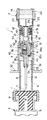
【図1】 本発明の実施の形態の注射器の構成及び構造を説明する注射器の断面図である。
【図2】 本発明の実施の形態の注射器の動きを説明する注射器の断面図である。
【符号の説明】
1 注射器
2 注射器本体
3 バイアル容器部
4 ジョイント部
6 円筒部
7 蓋体
9 ゴム栓
12 注入針
15 筒状部
17 ノズル
33 コア部
41 注入用流路
42 流路(吸引用流路)
43 逆止弁
45 フィルタ[0001]
BACKGROUND OF THE INVENTION
The present invention relates to a syringe that is used by dissolving a powder medicine or lyophilized preparation enclosed in a vial container with a dissolution liquid.
[0002]
[Prior art]
In general, when injecting powdered drugs or freeze-dried preparations, vial containers filled with these drugs and containers such as ampoules containing dissolved solutions are used, and these dissolved solutions and drugs are mixed together. The injection solution was injected by a syringe.
That is, first, the ampule solution is aspirated with a syringe, and then the injection needle of the syringe is inserted into a rubber stopper provided on the lid of the vial container to inject the solution into the vial container to dissolve it. Then, it was again sucked into the syringe, the needle was removed from the vial container, and the patient was injected.
By the way, in the case of the above methods, it takes time and effort to suck the solution into the syringe, and it is not preferable in terms of hygiene, and there is a problem that the needle tip is damaged. In this case, this problem can be avoided by replacing the injection needle of the syringe, but there is also a problem that much labor is required.
[0003]
For this reason, in Japanese Patent Application No. 40-6242, a container-use syringe pre-filled with a solution is prepared. On the other hand, the vial container is covered with a rubber stopper, and a dedicated cap is fitted to the vial container. The dedicated cap of the container and the syringe are sleeve-engaged by a joint, and the vial container and the syringe filled with the liquid medicine are integrated.
[0004]
[Problems to be solved by the invention]
According to the syringe having the above structure, it is possible to save the trouble of sucking the solution from the ampoule into the syringe or sucking the dissolved solution into the syringe again, but the needle tip is still damaged. Alternatively, it has not been possible to solve the problem of sucking an injection solution that has not been completely dissolved.
[0005]
The present invention has been made in view of the above circumstances, and can provide a syringe that can very easily draw only the completely injected solution into the syringe and that does not use a damaged needle tip. The purpose is to do.
[0006]
[Means for Solving the Problems]
In order to achieve the above object, the syringe according to claim 1 includes a vial container portion in which a medicine is sealed inside a container body, and an opening thereof is sealed by a lid through a rubber stopper, and a solution is contained inside. A filled syringe body, and a cylindrical portion whose one end is slidably connected to the cylindrical portion formed on the lid of the vial container portion in the direction of the vial container portion and the other end is provided at the distal end portion of the syringe body A cylindrical joint part detachably connected to the injection container, the joint part being provided with an injection needle on the vial container part side, and the syringe body side being detachably connected to the nozzle of the syringe body An injection channel provided with a check valve for flowing a fluid only from the syringe body side toward the injection needle, and from the injection needle side toward the syringe body. Only to flow fluid Has a check valve and a filter and a flow path provided in, by sliding the joint portion to the vial container portion direction, together with the core portion the joint, is moved into the vial container portion direction The injection needle is inserted into the rubber stopper from a hole formed in the lid of the vial container part, and the inside of the vial container part and the inside of the syringe body are communicated with each other through the injection needle and the flow path. It is characterized by that.
[0008]
DETAILED DESCRIPTION OF THE INVENTION
Hereinafter, embodiments of the syringe of the present invention will be described with reference to the drawings.
In FIG. 1, reference numeral 1 denotes a syringe. This syringe 1 has a syringe
The
[0009]
The
When a piston (not shown) of the
[0010]
The joint part 4 includes a vial-side connecting
A
[0011]
The syringe-
The
In addition, a
The
[0012]
A
And since these vial side space B and syringe side space T are each connected with the exterior via the
That is, ethylene oxide gas or vapor flows into the vial side space B from the
In addition, the structure in which the
[0013]
In addition, a holding
In addition, the code |
[0014]
Next, the usage of the syringe 1 having the above structure will be described along the procedure.
(1) First, a finger is put on the
In this way, as shown in FIG. 2, the
[0015]
(2) In this state, pressure is applied to the solution filled in the
In this way, the
Then, the solution that protrudes from the
Thereby, the solution is injected from the tip of the
[0016]
(3) When the medicine is dissolved in the injected solution to make an injection solution, the plunger of the
In this way, the injection solution is sucked from the
(4) When the injection solution is sucked into the
(5) Thereafter, by attaching an injection needle to the
[0017]
Thus, according to the syringe 1 having the above-described structure, the dissolved solution in the
Further, since the
In addition, since the
[0018]
In addition, since the injection of the solution into the
Further, the structure allows the
In addition, a
[0019]
【The invention's effect】
As described above, according to the syringe of the present invention, the following effects can be obtained.
According to the syringe of claim 1, the syringe is extremely easily discharged by discharging the solution from the nozzle of the syringe body in a state where the joint portion is pulled toward the vial container portion and the injection needle is inserted into the rubber stopper. The solution in the body can be injected into the vial container and can be mixed with the encapsulated drug.
In addition, since a dedicated injection needle for injecting the lysate into the vial container is used, it is possible to avoid the inconvenience of using the painful needle for injection into the patient.
In addition, since the injection of the solution into the vial container part and the suction of the injection solution from the vial container part can be performed in the joint part, the aseptic condition during the operation can be reliably maintained, which is extremely hygienic. It is.
In addition, since an injection flow path provided with a check valve is formed so as to allow fluid to flow only from the syringe body side toward the injection needle, it is possible to easily inject the solution from the syringe body into the vial container portion. Can do.
Furthermore, another check valve and a filter are provided in the flow path provided in the core so that the fluid flows only from the injection needle side toward the syringe body, so that the injection solution is reliably sucked into the syringe body. can do. That is, when the injection solution in the vial container is sucked into the syringe body, the undissolved medicine contained in the injection solution can be removed, and an extremely good injection solution is put into the syringe body. Can be captured.
[Brief description of the drawings]
FIG. 1 is a cross-sectional view of a syringe illustrating the configuration and structure of a syringe according to an embodiment of the present invention.
FIG. 2 is a cross-sectional view of the syringe for explaining the movement of the syringe according to the embodiment of the present invention.
[Explanation of symbols]
DESCRIPTION OF SYMBOLS 1
43
Claims (1)
該ジョイント部は、前記バイアル容器部側に注入針が設けられかつ前記注射器本体側が前記注射器本体のノズルに着脱可能に接続されたコア部を有し、
該コア部には、前記注射器本体側から前記注入針方向へのみ流体を流すべく逆止弁が設けられた注入用流路と、前記注入針側から前記注射器本体方向へのみ流体を流すべく他の逆止弁及びフィルタが設けられた流路とを有し、
前記ジョイント部を前記バイアル容器部方向へスライドさせることにより、前記コア部が前記ジョイント部とともに、前記バイアル容器部方向へ移動されて前記注入針が前記バイアル容器部の蓋体に形成された孔部から前記ゴム栓に刺し込まれ、前記注入針及び前記流路を介して前記バイアル容器部内と前記注射器本体内とが連通されることを特徴とする注射器。A vial container part in which a medicine is sealed inside a container body, the opening part of which is sealed with a lid through a rubber plug, a syringe body filled with a solution, and one end of the vial container part. A cylindrical joint portion that is slidably connected to the cylindrical portion formed in the direction of the vial container portion and the other end is detachably connected to the cylindrical portion provided at the distal end portion of the syringe body. ,
The joint part has a core part in which an injection needle is provided on the vial container part side and the syringe body side is detachably connected to a nozzle of the syringe body,
The core portion is provided with an injection flow path provided with a check valve for flowing a fluid only from the syringe body side to the injection needle direction, and another for flowing a fluid only from the injection needle side toward the syringe body. And a flow path provided with a check valve and a filter,
By sliding the joint part in the direction of the vial container part, the core part is moved in the direction of the vial container part together with the joint part, and the injection needle is formed in the lid of the vial container part. The syringe is inserted into the rubber stopper, and the inside of the vial container part and the inside of the syringe body are communicated with each other through the injection needle and the flow path.
Priority Applications (1)
| Application Number | Priority Date | Filing Date | Title |
|---|---|---|---|
| JP19496696A JP3759244B2 (en) | 1996-07-24 | 1996-07-24 | Syringe |
Applications Claiming Priority (1)
| Application Number | Priority Date | Filing Date | Title |
|---|---|---|---|
| JP19496696A JP3759244B2 (en) | 1996-07-24 | 1996-07-24 | Syringe |
Publications (2)
| Publication Number | Publication Date |
|---|---|
| JPH1033675A JPH1033675A (en) | 1998-02-10 |
| JP3759244B2 true JP3759244B2 (en) | 2006-03-22 |
Family
ID=16333307
Family Applications (1)
| Application Number | Title | Priority Date | Filing Date |
|---|---|---|---|
| JP19496696A Expired - Fee Related JP3759244B2 (en) | 1996-07-24 | 1996-07-24 | Syringe |
Country Status (1)
| Country | Link |
|---|---|
| JP (1) | JP3759244B2 (en) |
Families Citing this family (2)
| Publication number | Priority date | Publication date | Assignee | Title |
|---|---|---|---|---|
| JP2002177392A (en) | 2000-11-08 | 2002-06-25 | West Pharmaceutical Services Inc | Safety device of syringe |
| DE102004036051A1 (en) * | 2004-07-24 | 2006-02-16 | Arzneimittel Gmbh Apotheker Vetter & Co. Ravensburg | Injection syringe for hypodermic, intravenous or intravenous injection, has barrel with distal and proximal ends, and finger member(s) configured to permit application of force by fingers of person's hand |
-
1996
- 1996-07-24 JP JP19496696A patent/JP3759244B2/en not_active Expired - Fee Related
Also Published As
| Publication number | Publication date |
|---|---|
| JPH1033675A (en) | 1998-02-10 |
Similar Documents
| Publication | Publication Date | Title |
|---|---|---|
| JP4112009B2 (en) | Adapter and nozzle for syringe loading | |
| EP0817654B1 (en) | Pre-filled syringe drug delivery system | |
| US5533994A (en) | Storage and transfer bottle designed for storing two components of a medicamental substance | |
| US7637889B2 (en) | Drug delivery device with sliding valve and methodology | |
| RU2258537C2 (en) | Apparatus for preparing of therapeutic suspension or dispersion system and packaging method | |
| EP0282545B1 (en) | Connector and a disposable assembly utilizing said connector | |
| US5169385A (en) | Safety I. V. drug introducer set | |
| CA2071280A1 (en) | Transfer adaptors | |
| US8382713B2 (en) | Drug delivery device and methodology | |
| CZ284900B6 (en) | In advance filled syringe for storage and discharge of a liquid and sterile therapeutic substance | |
| KR980008252A (en) | Syringe Filling and Carrying Device | |
| JP2010540066A (en) | Liquid drug delivery device for use with a syringe having an enlarged tip | |
| JPH0380029B2 (en) | ||
| JPH04231051A (en) | Suction/transfer assembly for medicine liquid | |
| CZ20013506A3 (en) | Teat nozzle for dosing device and connection means therefor | |
| CA3135248C (en) | Liquid transfer device with dual lumen iv spike | |
| JPS6072561A (en) | Two-drug component syringe having vein display capacity | |
| JP2013514113A (en) | Syringe | |
| EP3562753B1 (en) | Container closure operated by a connecting device | |
| US11529467B2 (en) | Container adapter, delivery assembly and method of delivering a liquid to a patient | |
| US20020065490A1 (en) | Syringe for medical purposes | |
| JP2004147959A (en) | Two-component mixing type prefilled syringe | |
| JP3759244B2 (en) | Syringe | |
| EP2399565A1 (en) | Device for dosed reconstitution and administration of liquid solutions containing active substances available in separate form, in particular in powder or gel form | |
| JP4144027B2 (en) | Two-component prefilled syringe |
Legal Events
| Date | Code | Title | Description |
|---|---|---|---|
| A131 | Notification of reasons for refusal |
Free format text: JAPANESE INTERMEDIATE CODE: A131 Effective date: 20050823 |
|
| A521 | Written amendment |
Free format text: JAPANESE INTERMEDIATE CODE: A523 Effective date: 20051021 |
|
| TRDD | Decision of grant or rejection written | ||
| A01 | Written decision to grant a patent or to grant a registration (utility model) |
Free format text: JAPANESE INTERMEDIATE CODE: A01 Effective date: 20051220 |
|
| A61 | First payment of annual fees (during grant procedure) |
Free format text: JAPANESE INTERMEDIATE CODE: A61 Effective date: 20051228 |
|
| R150 | Certificate of patent or registration of utility model |
Free format text: JAPANESE INTERMEDIATE CODE: R150 |
|
| LAPS | Cancellation because of no payment of annual fees |