JP3744359B2 - Suspended load installation equipment - Google Patents
Suspended load installation equipment Download PDFInfo
- Publication number
- JP3744359B2 JP3744359B2 JP2001027503A JP2001027503A JP3744359B2 JP 3744359 B2 JP3744359 B2 JP 3744359B2 JP 2001027503 A JP2001027503 A JP 2001027503A JP 2001027503 A JP2001027503 A JP 2001027503A JP 3744359 B2 JP3744359 B2 JP 3744359B2
- Authority
- JP
- Japan
- Prior art keywords
- load
- tension
- ground
- differential value
- motor
- Prior art date
- Legal status (The legal status is an assumption and is not a legal conclusion. Google has not performed a legal analysis and makes no representation as to the accuracy of the status listed.)
- Expired - Fee Related
Links
- 238000009434 installation Methods 0.000 title claims description 45
- 239000000725 suspension Substances 0.000 claims description 25
- 238000004804 winding Methods 0.000 claims description 7
- 238000001514 detection method Methods 0.000 claims description 4
- 230000035939 shock Effects 0.000 claims description 2
- 230000003116 impacting effect Effects 0.000 description 4
- 238000010586 diagram Methods 0.000 description 3
- 238000000034 method Methods 0.000 description 3
- 238000009412 basement excavation Methods 0.000 description 1
- 238000010276 construction Methods 0.000 description 1
- 230000000694 effects Effects 0.000 description 1
Images




Landscapes
- Earth Drilling (AREA)
- Control And Safety Of Cranes (AREA)
Description
【0001】
【発明の属する技術分野】
本発明は機器設定用の吊荷の地切据付装置に関し,詳細には,吊り上げ操作時または吊り下げ操作時の衝撃を回避し,安全に吊搬作業を行うための吊荷の地切据付装置に関する。
【0002】
【従来の技術および発明が解決しようとする課題】
従来,工場や建設現場等で重量物を搬入,据付するような場合にはクレーンやチェーンブロック等の吊搬装置が用いられている。しかしながら,これらの吊搬装置で地上に置かれた荷を吊り上げたり,既に吊り上げられた状態の荷を目的の位置に据え付けたりする際には,荷に衝撃を与えないよう細心の注意を払いながら装置を操作する必要があった。
さらに,荷を姿勢変化させたり水平を保持する場合,複数の吊り下げ部材の巻き上げまたは巻き出し操作を同時に的確に操作することが困難であるという課題があった。
【0003】
本発明はこのような課題を解決するためになされたもので,複数のワイヤやチェーンによって多点吊りした荷において,吊り上げ開始時又は,据付時の衝撃が自動操作により回避可能である装置を提供することを目的とする。
【0004】
【課題を解決するための手段】
前記目的を達成するために,本願発明に係る吊荷の地切据付装置は以下に示す構成をなすものである。
すなわち,複数の吊り下げ部材により異なる位置において荷を吊持し,モータの駆動により,それぞれの吊り下げ部材を巻き上げ,或いは,巻き出しする複数の駆動手段と,前記吊り下げ部材に作用する張力をそれぞれ検出する複数の張力検出手段を備えた吊荷の地切据付装置であって,前記荷の吊り上げまたは吊り下げ操作時に,前記張力検出手段によって検出した張力信号の変化の割合に基づいて,張力信号の変化の割合がより大きな吊り下げ部材を支持する駆動手段については前記モータの回転数を減速し,前記張力信号の変化の割合がより小さな吊り下げ部材を支持する駆動手段については前記モータの回転数を増速させる制御を行い,荷に作用する衝撃を減少させる制御手段を備えたことを特徴とする吊荷の地切据付装置である。
【0005】
また,前記張力検出手段は,前記モータに配設されたトルクセンサであることを特徴とする。
【0006】
さらに,前記吊り下げ部材はワイヤであって,該ワイヤは前記モータにダイレクトドライブされていることを特徴とする。
【0007】
【発明の実施の形態】
以下,本発明に係る吊荷の地切据付装置の実施の形態について,添付図面に従って詳細に説明する。
【0008】
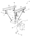
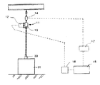
図1は本発明に係る吊荷の地切据付装置の全体横成を示す斜視図である。また,図2は本発明に係る吊荷の地切据付装置の全体構成と制御系の構成を示す説明図である。
吊荷の地切据付装置10は,複数の電動チェーンブロック11と,各々のチェーンブロック11に設けられた荷重センサ14と,各々のチェーンブロック11に設けられたサーボモータ12を制御する制御装置15を主要な構成としている。
【0009】
各電動チェーンブロック11は,制御装置15によりモータドライバ18を介してサーボモータ12を作動させることにより,チェーンブロック13を巻き上げまたは巻き出し制御するよう構成されている。電動チェーンブロック11の一端は荷重センサ14及び吊金具33を介して梁32に連結され,他端は吊金具33を介して荷31に連結されている。本実施の形態では,図1に示すように4台の電動チェーンブロック11によって荷31のコーナー部を吊時し,荷31を多点吊りしている。
【0010】
各チェーンブロック13は,ラチェツト機構を内蔵しており,サーボモータ12に供給する電力が停止した場合でも,荷31の落下を防止することが可能となっている。尚,本発明に係る吊荷の地切据付装置10のアクチュエータは,電動チェ一ンブロック11に限らず,例えば,モータとワイヤで構成されるダイレクトドライブ方式のものも適用可能である。また,吊り下げ部材としては,チェーン,ワイヤ,ロープ等の種々の部材が使用できる。
【0011】
荷重センサ14は,電動チェーンブロック11のチェーン張力を検出することができる任意の位置に取り付けられている。本実施の形態においては,電動チェーンブロック11と梁32の間に取り付けている。
チェーン張力は荷重センサ14により計測され,動歪アンプ17により電気信号に変換され,該電気信号が制御装置15に加えられる。尚,チェーンの張力を検出する張力検出手段は,荷重センサ14に限らず,チェーンの張力情報を検出することができるものであれば,いかなるものでもよい。例えば,トルクセンサでモータの負荷トルクを検出するものでもよい。
【0012】
また,マニュアルコントロールボックス23は,メインスイッチ24,マニュアルスイッチ25,自動吊り上げ(地切)スイッチ26,自動吊り下げ(据付)スイッチ27,及び緊急停止スイッチ28から構成され,これらのスイッチの出力は制御装置15に加えられる。
【0013】
制御装置15は,前記荷重センサ14及び動歪アンプ17から入力された各チェーンの張力値より,それぞれの張力信号の微分値を算出し,当該張力信号の微分値及びマニュアルコントロールボックス23の各スイッチの操作信号に基づいて各電動チェーンブロック11のサーボモータ12をそれぞれ駆動させる駆動信号を,モータドライバ18を介して出力する。尚,図2において,19は,各チェーンの張力値,張力信号の微分値,緊急停止情報,その他の各種の情報を表示するモニタである。
【0014】
次に,上記構成の吊荷の地切据付装置10の動作について,図3に示すフローチャートを参照しながら説明する。
前記吊荷の地切据付装置10は.マニュアルコントロールボックス23のメインスイッチ24がONされて動作がスタートすると,初期化処理を実行した後(ステップS10),次の3つの状態が選択可能となる。
【0015】
すなわち,マニュアルコントロールボックス23を使用して荷31を移動可能とする第1の移動状態と,自動吊り上げスイッチによって,地上に置かれた荷31に衝撃を与えることなく吊り上げを開始することを可能とする第2の移動状態,さらに,既に吊り上げられた荷31に衝撃を与えることなく地上又は対象物に据え付けることを可能とする第3の移動状態である。
【0016】
ステップS11では,マニュアルコントロールボックス23のマニュアルスイッチ25が操作(ON)されたか否かを判別し,マニュアルスイッチ25がONされると,第1の移動状態となる。第1の移動状態では.マニュアルスイッチ25の操作によって各電動チェーンブロック11のサーボモータ12をそれぞれ駆動させ(ステップS12),荷31を移動させる。
前記マニュアルスイッチ25がOFFされると各サーボモータ12は停止し待機状態となる。
【0017】
ステップS13では,自動吊り上げ(地切)スイッチ26が操作(ON)されたか否かを判断し,自動吊り上げ(地切)スイッチ26がONされると,第2の移動状態となる。第2の移動状態では,自動吊り上げ(地切)スイッチ26の開始信号により,各電動チェーンブロック11のサーボモータ12をそれぞれ駆動させ(ステップS14〜ステップS19),荷31に衝撃を与えること無く自動で吊り上げることができる。
【0018】
すなわち,自動吊り上げ(地切)スイッチ26がONされると,荷重センサ14により検出された張力値から張力信号の微分値が算出される。前記張力信号の微分値が0の時,チェーン張力に変化は起きていない。即ち吊り上げ開始前であることがわかる。そこで各チェーンブロックに与えられる張力信号の微分値を検出し0であるか判別を行い(ステップS14),張力信号の微分値が0である場合,サーボモータ12が巻上動作を開始する(ステップS15)。こうして,張力信号の微分値の検出および判別によるサーボモータ12の制御をすべてのチェーンに負荷が与えられるまで繰り返し行う。
【0019】
すべてのチェーンにおいて負荷が与えられた後,各サーボモータ12によりチェーンを微速で巻き上げる(ステップS16)。巻き上げ時において,各チェーンにおける張力信号の微分値を比較し(ステップS17),チェーンにおける張力信号の微分値がより小さい箇所は,サーボモータ12の駆動を増速し(ステップS18),チェーンにおける張力信号の微分値がより大きい箇所は,サーボモータ12の駆動を減速させる(ステップS18)。以上の操作(ステップS16〜ステップS18)をすべての張力信号の微分値が0になるまで行う(ステップS19)。すべてのチェーンにおける張力信号の微分値が0になる時,荷31は地面から吊り上げられた状態になり,自動吊り上げ(地切)スイッチ26による動作が終了しサーボモータ12は待機状態となる(ステップS20)。
【0020】
ステップS21では,自動吊り下げ(据付)スイッチ27が操作(ON)されたか否かを判別し,自動吊り下げ(据付)スイッチ27がONされると,第3の移動状態となる。第3の移動状態では,自動吊り下げ(据付)スイッチ26の開始信号により,各電動チェーンブロック11のサーボモータ12がそれぞれ駆動し(ステップS22〜ステップS27),荷31に衝撃を与えることなく自動で吊り下げ据付が行われる。
【0021】
自動吊り下げ(据付)スイッチ27がONされると,荷重センサ14により検出された張力値から張力信号の微分値が算出される。前記微分値が0の時,チェーン張力に変化は起きていない。即ち吊り下げ開始前であることがわかる。そこで各チェーンブロックに与えられる張力信号の微分値を検出し0であるか判別を行い(ステップS22),張力信号の微分値が0である場合,サーボモータ12が巻き下げ動作を開始する(ステップS23)。こうして,張力信号の微分値の検出および判別によるサーボモータ12の制御をすべてのチェーンにおいて張力の減少がなされるまで繰り返し行う。
【0022】
すべてのチェーンにおいて張力の減少がなされた後,各サーボモータ12によりチェーンを微速で巻き下げる(ステップS24)。巻き下げ時において,各チェーンブロックにおける張力信号の微分値を比較し(ステップS25),チェーンにおける張力信号の微分値がより小さいものは,サーボモータ12の駆動を増速し(ステップS26),チェーンにおける張力信号の微分値がより大きいものは,サーボモータ12の駆動を減速させる(ステップS26)。以上の操作(ステップS24〜S26)をすべてのチェーンにおける張力信号の微分値が0になるまで行う(ステップS27)。すべての張力信号の微分値が0になる時,荷31は地面に据付られた状態になり,自動吊り下げ(据付)スイッチ27による動作が終了しサーボモータ12は待機状態となる(ステップS28)。
【0023】
また,すべての状態において,緊急停止スイッチ28の信号が発信された場合は,サーボモータ12は直ちに待機状態となる。
以上で説明した操作によって荷31を移動すれば,作業者が細心の注意を払う必要がある吊り上げ関始時と据付時の荷31の移動を自動で安全に行うことができる。
本実施形態においては,4台の電動チェーンブロックを使用したが,荷31を多点吊する巻上装置の数量に制限はなく,同様の制御方法で,荷31に衝撃を与えることなく吊り上げ開始と据付を行なうことができる。また,許容荷重の小さな巻き上げ,巻き下げ装置を多数使用することで,重量物を繊細に移動させることもできる。
【0024】
図4は,前記発明において,荷の水平角を計測する傾斜計を取りつけた吊荷の地切据付装置10を示した説明図である。図4における吊荷の地切据付装置10は,荷31上に傾斜計60が取り付けられており,荷31の傾斜状態を計測することを可能とするものである。計測した角度情報は制御装置15に伝達され,該角度情報および張力信号の微分値に基づいて,駆動信号をモータドライバ18を介して出力することにより各電動チェーンブロック11のサーボモータ12をそれぞれ駆動させることにより,荷31の水平を保ち,かつ,衝撃を与えずに吊搬作業が可能となる。
【0025】
荷31の水平状態を設定する方法としては,マニュアルコントロールボックス23から,水平を設定する信号入力があると,傾斜計の角度情報を検出し,制御装置15は計測した角度情報に基づいて,各電動チェーンブロック11を一つずつ予め設定した範囲で,巻き上げおよび巻き下げ動作を行ない,荷31を水平状態で停止させることができる。
【0026】
図5は,単数の巻き上げ,巻き下げ装置からなる吊荷の地切据付装置10の実施の形態を示した説明図である。図5における吊荷の地切据付装置10は,ひとつの電動チェーンブロック11によって荷31を吊持した例である。前記吊荷の地切据付装置10は,電動チェーンブロック11と,チェーンブロック11に設けられた荷重センサ14と,チェーンブロック11に設けられたサーボモータ12を制御する制御装置15を主要な構成としている。
【0027】
次に,この吊荷の地切据付装置10の動作について,図6に示すフローチャートを参照しながら説明する。
前記吊荷の地切据付装置10は,マニュアルコントロールボックス23のメインスイッチ24がONされて動作がスタートすると,初期化処理が(ステップS10)行われ,以下に示す2つの状態が選択可能となる。
【0028】
すなわち,自動吊り上げスイッチによって,地上に置かれた荷31に衝撃を与えることなく吊り上げを開始することを可能とする第1の移動状態,さらに,既に吊り上げられた荷31に衝撃を与えることなく地上又は対象物に据え付けることを可能とする第2の移動状態である。
【0029】
マニュアルコントロールボックス23により,自動吊り上げ(地切)スイッチ26が操作(ON)されたか否かを判断し(ステップS13),自動吊り上げ(地切)スイッチ26がONされると,第1の移動状態となる。第1の移動状態では,自動吊り上げ(地切)スイッチ26の開始信号により,電動チェーンブロック11のサーボモータ12を駆動させ(ステップS14〜ステップS19),荷31に衝撃を与えること無く自動で吊り上げる。
【0030】
自動吊り上げ(地切)スイッチ26がONされると,荷重センサ14により検出された張力値から張力信号の微分値が算出される。前記張力信号の微分値が0の時,チェーン張力に変化は起きていない。即ち吊り上げ開始前であることがわかる。そこでチェーンブロックに与えられる張力信号の微分値を検出し0であるか判別を行い(ステップS14),張力信号の微分値が0である場合,サーボモータ12が巻上動作を開始する(ステップS15)。こうして,張力信号の微分値の検出および判別によるサーボモータ12の制御をチェーンに負荷が与えられるまで繰り返し行う。
【0031】
チェーンに負荷が与えられた後,サーボモータ12によりチェーンを微速で巻き上げる(ステップS16)。巻き上げ後,チェーンにおける張力信号の微分値を算出し(ステップS17),制御装置15に入力する。制御装置15は,入力された張力信号の微分値に応じて,モータドライバ18を介してサーボモータ12の駆動速度を制御するものである。ここに,制御装置15には,図7に示すようなチェーンにおける張力信号の微分値とサーボモータの駆動速度の関係式が予め入力されている。以上の操作(ステップS16〜S18)をチェーンにおける張力信号の微分値が0になるまで行う。チェーンにおける張力信号の微分値が0になる時,荷31は地面から吊り上げられた状態になり,自動吊り上げ(地切)スイッチ26による動作が終了しサーボモータ12は待機状態となる(ステップS20)。
【0032】
さらに,自動吊り下げ(据付)スイッチ27が操作(ON)されたか否かを判断し(ステップS21),自動吊り下げ(据付)スイッチ27がONされると,第2の移動状態となる。第2の移動状態では,自動吊り下げ(据付)スイッチ26の開始信号により,電動チェーンブロック11のサーボモータ12が駆動し(ステップS22〜ステップS27),荷31に衝撃を与えることなく自動で吊り下げ据付が行われる。
【0033】
自動吊り下げ(据付)スイッチ27がONされると,荷重センサ14により検出された張力値から張力信号の微分値が算出される。前記張力信号の微分値が0の時,チェーン張力に変化は起きていない。即ち吊り下げ開始前であることがわかる。そこでチェーンブロックに与えられる張力信号の微分値を検出し0であるか判別を行い(ステップS22),張力信号の微分値が0である場合,サーボモータ12が巻き下げ動作を開始する(ステップS23)。こうして,張力信号の微分値の検出および判別によるサーボモータ12の制御をチェーンにおいて除荷がなされるまで繰り返し行う。
【0034】
チェーンの除荷がなされた後,サーボモータ12によりチェーンを微速で巻き下げる(ステップS24)。巻き下げ後,チェーンブロックにおける張力信号の微分値を算出し(ステップS25),制御装置15に入力する。制御装置15は,入力された張力信号の微分値に応じて,モータドライバ18を介してサーボモータ12の駆動速度を制御するものである。ここに,制御装置15には,図7に示すようなチェーンにおける張力信号の微分値とサーボモータの駆動速度の関係式が予め入力されている。以上の操作(ステップS24〜S26)をチェーンにおける張力信号の微分値が0になるまで行う。チェーンにおける張力信号の微分値が0になる時,荷31は地面に据付られた状態になり,自動吊り下げ(据付)スイッチ27による動作が終了しサーボモータ12は待機状態となる(ステップS28)。
また,すべての状態において,緊急停止スイッチ28の信号が発信された場合は,サーボモータ12は直ちに待機状態となる。
【0035】
【発明の効果】
以上説明したように,本発明によれば,それぞれ独立した巻上装置を複数台用いて荷を多点吊りする場合において,荷の吊り上げ操作時,又は吊り下げ操作時に,張力検出手段によって検出した吊り下げ部材に作用する張力信号の微分値に基づいて,張力信号の微分値がより大きな吊り下げ部材を支持する駆動手段のモータ回転数を減速し,前記張力信号の微分値がより小さな吊り下げ部材を支持する駆動手段のモータ回転数を増速させる制御を行い,荷に作用する衝撃を減少させ,地切および据付作業が安全に行うことができる。
【図面の簡単な説明】
【図1】 本発明に係る吊荷の地切据付装置の全体構成を示す斜視図である。
【図2】 本発明に係る吊荷の地切据付装置の全体構成および制御系の構成を示す説明図である。
【図3】 図1に示した吊荷の地切据付装置の作用を説明するフローチャートである。
【図4】 荷に傾斜計を付加した吊荷の地切据付装置の全体構成を示す図である。
【図5】 巻き上げ,巻き下げ装置が単数である場合の吊荷の地切据付装置の全体構成を示す正面図である。
【図6】 図5に示した吊荷の地切据付装置の作用を説明するフローチャートである。
【図7】 チェーンにおける張力信号の微分値とサーボモータの駆動速度の関係式を示すグラフである。
【符号の説明】
10 吊荷の地切据付装置
11 電動チェーンブロック
12 サーボモータ
14 荷重センサ
15 制御装置
23 マニュアルコントロールボックス
31 荷
60 傾斜計[0001]
BACKGROUND OF THE INVENTION
BACKGROUND OF THE INVENTION 1. Field of the Invention The present invention relates to a suspended load grounding installation device for equipment setting, and more particularly to a suspended load grounding installation device for avoiding an impact during a lifting operation or a hanging operation and performing a lifting work safely. About.
[0002]
[Background Art and Problems to be Solved by the Invention]
Conventionally, when carrying and installing heavy objects at factories, construction sites, etc., suspension devices such as cranes and chain blocks have been used. However, or on up hanging load placed on the ground in these Tsu搬device, when or mounting a load already lifting was state to the desired location, the close attention so as not to impact the load It was necessary to operate the device while paying.
Furthermore, when changing the posture of the load or maintaining the level, there is a problem that it is difficult to accurately and simultaneously operate the hoisting or unwinding operations of a plurality of suspension members.
[0003]
The present invention has been made in order to solve such problems, in the multi-point suspension the load by a plurality of wires or chains, lifting inception or, the device impact during installation can be avoided by automatic operation The purpose is to provide.
[0004]
[Means for Solving the Problems]
In order to achieve the above object, the suspended load ground-cutting installation device according to the present invention has the following configuration.
That is, a plurality of suspension members are used to suspend a load at different positions, and by driving a motor, a plurality of drive means for winding or unwinding each suspension member, and tension acting on the suspension member. A suspended ground excavation installation device comprising a plurality of tension detection means for detecting each of the tensions based on a change rate of a tension signal detected by the tension detection means during the lifting or hanging operation of the load. The drive means for supporting the suspension member with a larger signal change rate reduces the rotational speed of the motor and the drive means for supporting the suspension member with a smaller change rate of the tension signal A suspended load ground-cutting installation device characterized by comprising control means for controlling the speed of rotation to increase and reducing the impact acting on the load.
[0005]
The tension detecting means is a torque sensor disposed in the motor .
[0006]
Further, the suspension member is a wire, and the wire is directly driven by the motor .
[0007]
DETAILED DESCRIPTION OF THE INVENTION
DESCRIPTION OF THE PREFERRED EMBODIMENTS Embodiments of a suspended load ground-cutting installation device according to the present invention will be described below in detail with reference to the accompanying drawings.
[0008]
FIG. 1 is a perspective view showing the entire horizontal installation of the suspended load ground-cutting installation apparatus according to the present invention. Moreover, FIG. 2 is explanatory drawing which shows the whole structure and the structure of a control system of the suspended earth ground installation apparatus based on this invention.
The suspended load
[0009]
Each
[0010]
Each
[0011]
The
The chain tension is measured by the
[0012]
The
[0013]
The
[0014]
Next, the operation of the suspended load ground
The suspended load ground-
[0015]
That is, the first moving state in which the
[0016]
In step S11, it is determined whether or not the
When the
[0017]
In step S13, it is determined whether or not the automatic lifting (ground cutting)
[0018]
That is, when the automatic lifting (ground cutting)
[0019]
After the load is applied to all the chains, the chains are wound at a very low speed by each servo motor 12 (step S16). At the time of winding, the differential value of the tension signal in each chain is compared (step S17). If the differential value of the tension signal in the chain is smaller, the drive of the
[0020]
In step S21, it is determined whether or not the automatic suspension (installation)
[0021]
When the automatic suspension (installation)
[0022]
After reduction of the tension is made in all chains, the
[0023]
In all states, when the signal of the
If the
In the present embodiment, four electric chain blocks are used. However, the number of hoisting devices that suspend the
[0024]
FIG. 4 is an explanatory diagram showing the suspended load ground-cutting
[0025]
As a method of setting the horizontal state of the
[0026]
FIG. 5 is an explanatory view showing an embodiment of the suspended load ground-cutting
[0027]
Next, the operation of the suspended load ground-cutting
When the
[0028]
That is, the automatic lifting switch, a first movement state which makes it possible to start up hanging without impacting the
[0029]
It is determined whether or not the automatic lifting (ground cutting)
[0030]
When the automatic lifting (ground cutting)
[0031]
After a load is applied to the chain, the
[0032]
Further, it is determined whether or not the automatic suspending (installation)
[0033]
When the automatic suspension (installation)
[0034]
After unloading of the chain is made, lowering wind the chain in the fine speed by the servo motor 12 (step S24). After the lowering, the differential value of the tension signal in the chain block is calculated (step S25) and input to the
In all states, when the signal of the
[0035]
【The invention's effect】
As described above, according to the present invention, when a load is suspended at multiple points using a plurality of independent hoisting devices, the load is detected by the tension detecting means at the time of lifting or hanging the load. Based on the differential value of the tension signal acting on the suspension member, the motor rotation speed of the driving means that supports the suspension member having a larger differential value of the tension signal is reduced, and the differential value of the tension signal is smaller. Control to increase the motor rotation speed of the driving means for supporting the member is performed, the impact acting on the load is reduced, and the ground cutting and installation work can be performed safely.
[Brief description of the drawings]
FIG. 1 is a perspective view showing the overall configuration of a suspended load ground-cutting installation apparatus according to the present invention.
FIG. 2 is an explanatory diagram showing an overall configuration of a suspended load ground-cutting installation device and a configuration of a control system according to the present invention.
FIG. 3 is a flowchart for explaining the operation of the suspended load ground-cutting installation device shown in FIG. 1;
FIG. 4 is a diagram showing an overall configuration of a suspended load ground-cutting installation device in which an inclinometer is added to the load.
FIG. 5 is a front view showing the entire configuration of the suspended load ground-cutting installation device when a single hoisting and lowering device is used.
6 is a flowchart for explaining the operation of the suspended load ground-cutting installation device shown in FIG. 5;
FIG. 7 is a graph showing a relational expression between a differential value of a tension signal in a chain and a driving speed of a servo motor.
[Explanation of symbols]
DESCRIPTION OF
Claims (3)
前記吊り下げ部材に作用する張力をそれぞれ検出する複数の張力検出手段を備えた吊荷の地切据付装置であって,
前記荷の吊り上げまたは吊り下げ操作時に,前記張力検出手段によって検出した張力信号の変化の割合に基づいて,張力信号の変化の割合がより大きな吊り下げ部材を支持する駆動手段については前記モータの回転数を減速し,前記張力信号の変化の割合がより小さな吊り下げ部材を支持する駆動手段については前記モータの回転数を増速させる制御を行い,荷に作用する衝撃を減少させる制御手段を備えたことを特徴とする吊荷の地切据付装置。A plurality of driving means for suspending a load at different positions by a plurality of suspension members and winding or unwinding each suspension member by driving a motor;
A suspended load grounding installation device comprising a plurality of tension detection means for detecting tension acting on the suspension member,
Rotation of the motor for the driving means for supporting the suspension member having a larger change rate of the tension signal based on the change rate of the tension signal detected by the tension detection means at the time of lifting or hanging the load. Control means for reducing the number of shocks and controlling the speed of the motor to increase the speed of the driving means for supporting the suspension member with a smaller rate of change in the tension signal, and reducing the impact acting on the load. A suspended load ground-cutting installation device characterized by that.
Priority Applications (1)
| Application Number | Priority Date | Filing Date | Title |
|---|---|---|---|
| JP2001027503A JP3744359B2 (en) | 2001-02-02 | 2001-02-02 | Suspended load installation equipment |
Applications Claiming Priority (1)
| Application Number | Priority Date | Filing Date | Title |
|---|---|---|---|
| JP2001027503A JP3744359B2 (en) | 2001-02-02 | 2001-02-02 | Suspended load installation equipment |
Publications (2)
| Publication Number | Publication Date |
|---|---|
| JP2002226181A JP2002226181A (en) | 2002-08-14 |
| JP3744359B2 true JP3744359B2 (en) | 2006-02-08 |
Family
ID=18892150
Family Applications (1)
| Application Number | Title | Priority Date | Filing Date |
|---|---|---|---|
| JP2001027503A Expired - Fee Related JP3744359B2 (en) | 2001-02-02 | 2001-02-02 | Suspended load installation equipment |
Country Status (1)
| Country | Link |
|---|---|
| JP (1) | JP3744359B2 (en) |
Families Citing this family (1)
| Publication number | Priority date | Publication date | Assignee | Title |
|---|---|---|---|---|
| JP6646268B1 (en) * | 2019-06-14 | 2020-02-14 | 東芝ロジスティクス株式会社 | Center of gravity detection device and center of gravity detection method |
-
2001
- 2001-02-02 JP JP2001027503A patent/JP3744359B2/en not_active Expired - Fee Related
Also Published As
| Publication number | Publication date |
|---|---|
| JP2002226181A (en) | 2002-08-14 |
Similar Documents
| Publication | Publication Date | Title |
|---|---|---|
| CN103998367B (en) | Crane control | |
| CA2098894C (en) | Method for checking brake torque | |
| CN114007977B (en) | Controller, boom device, and crane | |
| EP1773706A1 (en) | Hoisting-cable drive comprising a single bottom-hook block and two winches | |
| CN114014164B (en) | A crane hook vertical control system and control method thereof | |
| JP2022143232A (en) | crane | |
| JP3056915B2 (en) | Vertical crane control for crane | |
| JP2019123570A (en) | Height adjustment auxiliary apparatus, crane therewith and height adjustment method | |
| JPH09267972A (en) | Cable drum drive | |
| JP7189489B2 (en) | mobile cranes and crane systems | |
| US20210114848A1 (en) | Cantilevered lifting beam system | |
| JP3434401B2 (en) | Crane hook overwind prevention device | |
| JPH08277094A (en) | Automatic aligning hoisting accessory | |
| JP2000191277A (en) | Method and device for compensating deformation of boom | |
| JPH01256496A (en) | Load vibration preventer at time of ungrounding of slinging load of crane with boom | |
| JPH03284598A (en) | Perpendicular off-ground control device of hanging load on crane | |
| JP2002160891A (en) | Hoisting accessory height control method and hoisting accessory height control system for crane | |
| JP3649781B2 (en) | Tower crane safety equipment | |
| JPH11139771A (en) | Crane turning deceleration control device and control method thereof | |
| JP2002226181A (en) | Lifting device | |
| JP2636323B2 (en) | Turning speed control device for construction tower crane | |
| JP7132821B2 (en) | Work vehicle safety device | |
| JP3229679B2 (en) | Control device for hydraulically driven winch in mobile crane | |
| JP3255461B2 (en) | Control device for hydraulically driven winch in mobile crane | |
| JP2918720B2 (en) | Jib hoist angle constant control device for mobile crane |
Legal Events
| Date | Code | Title | Description |
|---|---|---|---|
| A977 | Report on retrieval |
Free format text: JAPANESE INTERMEDIATE CODE: A971007 Effective date: 20050113 |
|
| A131 | Notification of reasons for refusal |
Free format text: JAPANESE INTERMEDIATE CODE: A131 Effective date: 20050308 |
|
| A521 | Written amendment |
Free format text: JAPANESE INTERMEDIATE CODE: A523 Effective date: 20050509 |
|
| TRDD | Decision of grant or rejection written | ||
| A01 | Written decision to grant a patent or to grant a registration (utility model) |
Free format text: JAPANESE INTERMEDIATE CODE: A01 Effective date: 20051101 |
|
| A61 | First payment of annual fees (during grant procedure) |
Free format text: JAPANESE INTERMEDIATE CODE: A61 Effective date: 20051114 |
|
| R150 | Certificate of patent or registration of utility model |
Free format text: JAPANESE INTERMEDIATE CODE: R150 |
|
| S533 | Written request for registration of change of name |
Free format text: JAPANESE INTERMEDIATE CODE: R313533 |
|
| R350 | Written notification of registration of transfer |
Free format text: JAPANESE INTERMEDIATE CODE: R350 |
|
| FPAY | Renewal fee payment (event date is renewal date of database) |
Free format text: PAYMENT UNTIL: 20081202 Year of fee payment: 3 |
|
| FPAY | Renewal fee payment (event date is renewal date of database) |
Free format text: PAYMENT UNTIL: 20091202 Year of fee payment: 4 |
|
| FPAY | Renewal fee payment (event date is renewal date of database) |
Free format text: PAYMENT UNTIL: 20101202 Year of fee payment: 5 |
|
| FPAY | Renewal fee payment (event date is renewal date of database) |
Free format text: PAYMENT UNTIL: 20101202 Year of fee payment: 5 |
|
| FPAY | Renewal fee payment (event date is renewal date of database) |
Free format text: PAYMENT UNTIL: 20111202 Year of fee payment: 6 |
|
| FPAY | Renewal fee payment (event date is renewal date of database) |
Free format text: PAYMENT UNTIL: 20111202 Year of fee payment: 6 |
|
| FPAY | Renewal fee payment (event date is renewal date of database) |
Free format text: PAYMENT UNTIL: 20121202 Year of fee payment: 7 |
|
| FPAY | Renewal fee payment (event date is renewal date of database) |
Free format text: PAYMENT UNTIL: 20131202 Year of fee payment: 8 |
|
| S111 | Request for change of ownership or part of ownership |
Free format text: JAPANESE INTERMEDIATE CODE: R313111 |
|
| R350 | Written notification of registration of transfer |
Free format text: JAPANESE INTERMEDIATE CODE: R350 |
|
| S111 | Request for change of ownership or part of ownership |
Free format text: JAPANESE INTERMEDIATE CODE: R313113 |
|
| R350 | Written notification of registration of transfer |
Free format text: JAPANESE INTERMEDIATE CODE: R350 |
|
| R250 | Receipt of annual fees |
Free format text: JAPANESE INTERMEDIATE CODE: R250 |
|
| LAPS | Cancellation because of no payment of annual fees |