JP3740249B2 - Sheet material feeding apparatus and image forming apparatus - Google Patents
Sheet material feeding apparatus and image forming apparatus Download PDFInfo
- Publication number
- JP3740249B2 JP3740249B2 JP10959397A JP10959397A JP3740249B2 JP 3740249 B2 JP3740249 B2 JP 3740249B2 JP 10959397 A JP10959397 A JP 10959397A JP 10959397 A JP10959397 A JP 10959397A JP 3740249 B2 JP3740249 B2 JP 3740249B2
- Authority
- JP
- Japan
- Prior art keywords
- sheet material
- gear
- sheet
- roller
- feeding device
- Prior art date
- Legal status (The legal status is an assumption and is not a legal conclusion. Google has not performed a legal analysis and makes no representation as to the accuracy of the status listed.)
- Expired - Fee Related
Links
Images


Description
【0001】
【発明の属する技術分野】
本発明は、プリンタ、複写機、ファクシミリ等の画像形成装置等の画像形成部にシート材を給送するシート材給送装置及び斯かるシート材給送装置を装備した画像形成装置に関するものである。
【0002】
【従来の技術】
従来、画像形成装置及びそれに具備されるシート材給送装置は多く製品化され、多種の給紙方式、分離方式等の仕様がある。
【0003】
これらの方式の中で、紙等のシート材を積載する中板にコイルバネを用い、該コイルバネの力に抗するストッパーに分離爪とリタードローラを用いた、いわゆる爪プラスリタード方式により分離するシート材給送装置が製品化されている。
しかし、この方式によるシート材給送装置は、その可能な給紙容量は少なく、信頼性が高くない。具体的には、給紙容量約250枚、その駆動系は高額な電磁クラッチ、ソレノイドを1給紙で1個ずつ使用している。電気的にもその制御が複雑で、オプション等の拡張性が容易でなく、給紙ビンの数も少ない。また、その給紙駆動の構成も複雑である。
【0004】
【発明が解決しようとする課題】
近年におけるエンドユーザのニーズはシート材給送装置のさまざまな形態に対する要望が多く、給紙容量の設定等を変えた製品ラインナップの多様化であらゆるユーザのニーズに対応する必要がある、また、それとは別に、各製品に対し小型化、低コスト化を図る必要がある、また、近年における環境問題に対応し、自動両面印字が可能な機構を持つことが望まれ、またシート材給送装置を具備する画像形成装置等のシステムとしての小型化を図ることが好ましい、また、エンドユーザのあらゆる紙種に対応しても給紙、搬送の信頼性向上、エンドユーザに調整等の作業をさせない必要がある、などのニーズがあるが、これらのニーズに対し、現状レベルでは十分とはいえない面がある。
【0005】
本発明は、これらのニーズを満たすべく、より小さくより安くオプションを含めた給紙容量を多様化した製品ラインナップで、且つ信頼性向上、具体的にはジャムしないといったあらゆるエンドユーザのニーズに対応するようにしたシート材給送装置を提供することを目的とする。
【0006】
【課題を解決するための手段】
上記目的を達成するために、第1の発明は、回転方向の一部にシート材との接触面を有する(以下、Dカット形状という)給紙ローラと、シート材を該給紙ローラに押圧するための押圧手段と、該押圧手段に対向してシート材を押えるシート材押え手段とを有するシート材給送装置において、シート材を給紙するための給紙信号を受けて前記給紙ローラを駆動し、一給紙動作のための回転(約一回転)で駆動を解除する給紙ローラの駆動手段を備え、該駆動手段は、一部を切り欠かれている欠歯ギアと、該欠歯ギアを回転付勢する付勢手段と、該付勢手段の付勢力に抗して前記欠歯ギアの回転を規制するソレノイドと、を備え、前記ソレノイドによる規制の解除とともに付勢手段によって回転力を与えられて前記欠歯ギアが回転して前記給紙ローラ側のギアに噛合って駆動力を前記給紙ローラに伝達し、一給紙動作後に再度前記ソレノイドにより規制することにより駆動力の伝達を解除するように構成され、給紙ローラの近傍にその駆動手段とは独立して設けられ、給紙ローラの一給紙動作後に該給紙ローラをホームポジションに位置させる固定手段を有することを特徴とする。
【0007】
第2の発明は、第1の発明において、給紙ローラ側のギアが前記給紙ローラの駆動軸に直結して設けられ、前記ホームポジションにおいて、欠歯ギアの欠歯部が給紙ローラの位相となり、駆動連結を解除することを特徴とする。
【0008】
第3の発明は、第1の発明において、固定手段が、給紙ローラをホームポジションに位置させるための付勢バネを有することを特徴とする。
【0011】
第4の発明は、回転方向の一部にシート材との接触面を有する給紙ローラと、シート材を該給紙ローラに押圧するための押圧手段と、該押圧手段に対向してシート材を押えるシート材押え手段と、シート材を分離するリタード分離手段を有するシート材給送装置において、シート材収納手段側にリタード分離手段及びその駆動手段を有し、シート材給送装置側に、前記駆動手段に駆動力を伝達するための第1の駆動伝達手段を、シート材給送装置側面のハウジング部にスナップフィッティングのみで固定し、該ハウジング部には該スナップフィッティング用の穴及び該第1の駆動伝達手段に駆動力を伝達するための第2の駆動伝達手段を中心とした円弧状の長穴を設け、該長穴の範囲内において前記第1の駆動伝達手段が揺動可能であることを特徴とする。
【0012】
第5の発明は、回転方向の一部にシート材との接触面を有する給紙ローラと、シート材を該給紙ローラに押圧するための押圧手段と、該押圧手段に対向してシート材を押さえるシート材押え手段と、シート材を分離するリタード分離手段と、を有するシート材給送装置において、給紙ローラ及びリタード分離手段に駆動を伝達するギア部が、両欠歯ギアが同軸上に配設され、さらに同軸上に少なくとも1つの欠歯ギアが設けられ、これらの3種の欠歯ギアが軸に対し回転不能に固定されて欠歯ギア列が形成され、該欠歯ギア列は、カム部と該カム部を回転方向に付勢する付勢手段を有し、該欠歯ギア列は、1つのソレノイドにより回転固定されるとともに、該ソレノイドのON、OFFによって回転制御され、該ギア列のそれぞれのギア位相の違いによって、前記給紙ローラ、フィードローラの回転タイミングを制御するように構成され、該ギア部によって、リタード分離手段は、シート材搬送方向と逆方向の逆転駆動が常に付与され、該リタード分離手段と対をなしてシート材を搬送するフィードローラはその搬送方向下流に位置する次の搬送ローラニップ部まで少なくともシート材を搬送し、その後は、フィードローラの駆動を停止しリタード分離手段に従動してシート材積載手段方向に逆回転されることを特徴とする。
【0013】
第6の発明は、第5の発明において、前記フィードローラの駆動軸に直結するギアへ駆動力を伝達するギアは、その一部が切欠された欠歯ギアからなることを特徴とする。
【0015】
第7の発明は、第5の発明において、前記給紙ローラ用の欠歯ギアの欠歯部位相と前記フィードローラ用の欠歯部位相とをずらして、該給紙ローラの動作タイミングを該フィードローラの動作タイミングより早くしたことを特徴とする。
【0016】
第8の発明は、第7の発明において、前記欠歯ギア列に、常に駆動しているアイドラギアをその同軸上に設けたことを特徴とする。
【0017】
第9の発明は、第8の発明において、前記アイドラギアが直接又は間接的にリタードローラを駆動し、且つ、その下段に設けた他のシート材給送装置側へシート材を搬送するための入力ギアに連結されていることを特徴とする。
【0018】
第10の発明は、回転方向の一部にシート材との接触面を有する給紙ローラと、シート材を該給紙ローラに押圧するための押圧手段と、該押圧手段に対向してシート材を押さえるシート材押え手段と、シート材を分離するリタード分離手段と、を有するシート材給送装置において、該リタード分離手段は、シート材収納手段側に設けられて、揺動アームにより支持され付勢手段によりフィードローラ側に付勢されるリタードローラを有し、前記揺動アームは、鉛直下方に取り付けられる別のシート材給送装置からのシート材搬送ガイドの一部もしくは全域を兼ねることを特徴とする。
【0020】
第11の発明は、シート材を給送するために回転方向の一部にシート材との接触面を有する給紙ローラと、シート材を該給紙ローラに押圧するための押圧手段と、該押圧手段に対向してシート材を押えるシート材押え手段と、を有するシート材給送装置と、該シート材給送装置の上部に配設され、該シート材給送装置からのシート材に画像を形成する画像形成部を具備する画像形成装置本体を有する画像形成装置において、前記シート材給送装置と画像形成装置本体との間に側面から装着可能な他のシート材給送装置を有し、該他のシート材給送装置から画像形成部へ向かうシート材が、前記シート材給送装置の給紙ローラの上方を通過し画像形成部へ給送するためのシート材給送路を有し、前記給紙ローラの軸はアームに支持され、該アームはフィードローラの回転軸を揺動軸として支持され、給紙ローラとシート材が接触しているピックアップ時には、該揺動軸より上方向に給紙ローラが揺動し、且つその揺動時における前記給紙ローラの突出面が前記シート材給送路とオーバーラップし、少なくとも該オーバーラップ分の切り欠き部材を該シート材給送路に設けたことを特徴とする。
【0021】
第12の発明は、第11の発明において、前記シート材給送装置の下段に更に他のシート材給送装置が装着可能とされ、前記3つのシート材給送装置から給送されるシート材が合流して画像形成部へ搬送される搬送路を有することを特徴とする。
【0023】
第13の発明は、第11乃至12のいずれかの発明において、側面から装着可能な前記他のシート材給送装置は、画像形成部から一度排出されたシート材を画像形成部へ再給送するシート材再給送手段であることを特徴とする。
【0027】
【発明の実施の形態】
(第1の実施形態)
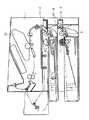
図1は本発明の第1の実施形態を示し、同図において、1は画像形成装置本体、2は該画像形成装置において紙等のシート材を給送するシート材給送装置、3はシート材給送装置内のシート材収納手段であるカセット、4はシート材を直接積載する中板、5はシート材の重さに打ち勝ち給紙ローラに搬送力を与えるバネ、6は該中板4の支点にて、該バネ5の付勢力でシート材が支点中心で回転するのを規制するシート材押さえ手段で、ここではシート材の分離機能を有する、いわゆる分離爪である。7は給紙ローラ、8はフィードローラ、9はリタードローラである。
【0028】
前記給紙ローラ7は、コントローラユニットから画像形成信号が出されると、ソレノイド(図中後記)をトリガにして始動回転される。次にある程度のディレイをおいて、フィードローラ8がシート材搬送方向に回転する。それと対のリタードローラ9は常時逆転駆動していて、トルクリミッタを介してフィードローラ8に従動回転し、付勢バネにて一定圧でフィードローラ8に押圧し、いわゆるリタード分離を行っている。
【0029】
フィードローラ8は一定量駆動してシート材を搬送し、そのシート材は搬送ローラ10、搬送ローラ11を経由して画像形成部12に搬送される。画像形成部12ではレーザ光等により露光されて電子写真方式等により感光ドラム12−1上に潜像が形成され、該潜像は現像手段により現像剤であるトナーによりトナー像として現像化され、トナー像は転写手段12−2によりシート剤に転写される。転写されたシート材は画像形成部12から、定着器13、排紙ローラ14、15を経由して機外に排紙される。このとき、両面印字のコマンドが出ているときは、フラッパ16が作用して両面ユニット内に搬送され、スイッチバックされたシート材が該画像形成装置内に再給紙され、裏側を印字して、同様のプロセスで機外に排紙される。
【0030】
本実施形態においては、図1のシート材給送装置2−1は約500枚のシート材をスタック、給紙可能で、図2のシート材給送装置2−2は約250枚とほぼ半分の構成をとっている。その他の画像形成部等は前述する図1と同様で、その動作説明も含めて省略する。
【0031】
このように、本実施形態では、基本的な給紙容量が異なる2種類のシート材給送装置を有する製品ラインナップを構成し、エンドユーザの多様化する要望に対応する。
【0032】
図3、図4はさらにエンドユーザの多様化した要望に対し、図1、図2のそれぞれの画像形成装置の最下位即ち図1、2のシート材給送装置2−1、2−2の下に、オプションでシート材給送装置2−Dがエンドユーザにより取り付け可能とされている。その具体的手段として、エンドユーザがシート材給送装置2−D上に画像形成装置本体1を乗せるだけで、装着が完結されるよう電気接点、位置決め嵌合ボス、その対応穴をそれぞれのシート材給送装置に有する。
【0033】
次に駆動系について説明すると、画像形成装置本体(以下、本体と省略)側からの駆動力をシート材給送装置側が受けるようになっている。本実施形態の構成では、オプションを含めシート材給送装置に関する駆動系は全て本体側に有する1個のモータのみで駆動を行っている。又そのシート材給送装置のユニット間とのギアはそれぞれ固定のギアで、モジュール1.5で0.5のバックラッシュ(ギアのがた)を有している。これは各ユニット間の寸法のばらつきを考慮しているためである。
【0034】
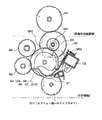
図6、図9〜図11により、シート材給送装置に関するシート材給送関連のギア部の構成について説明する。各シート材給送装置においては、同様の給紙方式、同様のシーケンスをとっているので、そのシーケンスに関するギア(具体的には後に述べる欠歯ギアの組み合わせにより行っている)類は同じでそれぞれのシート材給送装置間、又は本体間とのアイドラギア以外は同じになっている。
【0035】
G1は本体側のギアでここで本体とシート材給送装置との連結が各固定ギアによって行われている。G2はシート材給送装置側のギアで、減速によるギア比調節のため段ギアとなっている。G2はフィードローラ8と同軸8−2上におかれている。G3はアイドラギア、G4は欠歯ギアG5に連結するためのアイドラギア、G5はG5−cのカム部を含む欠歯ギアで、給紙信号により、ソレノイドGSが引かれ、レバーGTの付勢力でカム部が回動し、欠歯ギアがギアG4に連結して給紙シーケンスに入る。
【0036】
ギアG5には欠歯ギアG6、欠歯ギアG7がそれぞれ回転固定されており、ギアG5とともにギアG6、ギアG7が回転する。ギアG6は給紙ローラ即ちピックアップローラへ駆動伝達する駆動軸7−7に回転固定するギアG8にあるタイミングをもって連結する。ギアG7はフィードローラへ駆動伝達する駆動軸8−2に回転固定するギアG9にあるタイミングをもって連結する。従って、ギアG5の駆動連結とともにギアG8、ギアG9があるタイミングで駆動、さらに、ピックアップローラ7、フィードローラ8が回転を行う。
【0037】
この駆動シーケンスはギアG5、G6、G7(つまりはピックアップローラ7)が各1回転(一給紙動作)することをもって1シーケンスが終了する。そのため、ギアG8、ギアG9はシーケンス後はフリーになり、各ローラもフリーになる。そのため、ジャム処理も容易に行うことが可能で、且つ紙の力でローラ類を破壊するといった事故に対しても効果を有するとともにトルク削減の効果もある。また、給紙ローラであるピックアップローラはいわゆるDカットローラで、その回転方向の一部にのみシート材との接触面を有するため、そのホームポジションの位相合わせのためにカラー7−9を介して付勢バネ7−10と連結し、そうすることで、正規の位置(ホームポジション)にピックアップローラが回転固定される。
【0038】
ピックアップローラ7とフィードローラ8との駆動タイミングは、該欠歯ギアG6とG7との欠歯位相により調整可能で、本実施形態では、そのシート材がいわゆる分離爪6の正規の位置、又は分離爪6では分離しきれなかった残ったシート材がリタードローラ9で分離されて、該リタードローラ9ニップ部で待機している場合と2箇所有り、給紙のタイミングごとにシート材の先端がばらつき、ひいては紙間がばらつき多様なジャムのもとになることを防ぐため、ピックアップローラ7の起動からある一定の時間をおいてフィードローラ8を駆動動作させている。そうすることで、紙間のばらつきも一定範囲内に収まり、スループットが出ないといった大きなスペックダウンになるといったことが免れる。
【0039】
また、ギアG4はギアG5に連結するとともにギアG10に常時連結し、いわゆるアイドラ回転している。そして、ギア11を介して、オプションである下段に有するシート材給送装置に駆動連結する。またそれと同時にフィードローラ軸上にギアG11、ギアG12を介して軸とギアとが一体成形されるリタードギア9−6に連結し、そしてリタードローラが常時リミッタ9−2を介しシート材搬送方向に逆転駆動、いわゆるリタード分離を行っている。このリタードギア9−6はシート材カセット3に設けられ、ギアG12は振り子ギアで、シート材カセット3の位置精度に影響少なく連結固定される。
【0040】
図12はギアG12、そのハウジング、シート材カセット3の概要を表わす。ギアG12はスナップフィットのみでそのハウジング部に取り付け固定され、そのギアの回転力でシート材カセット3のギアであるリタードギア9−6側へ当接される。ギア11の回転力でギア12がリタードギア9−6側へ食い込みギア部の横にフランジ部を当接してギアのバックラッシュを確保している。リタードローラ8はシート材カセット3をシート材給送装置に挿入、固定されると同時にシート材給送装置側に固定されるフィードローラ8に圧接固定される。駆動は該リタードギア9−6を経由してジョイント9−5、ホルダー9−4に支持されるリタード軸9−3及びトルク発生手段たるトルクリミッタ9−2を介してリタードローラに連結し、その駆動とともにシート材搬送方向と逆転回転する。
【0041】
ギアG2、G10、G11とギアのアイドラ列はほぼ直線的に下方向に向かって配置され、且つ比較的に大径ギアでギア個数を最小にし、ギアによる伝達トルクのロス、騒音等を防止している。また、同一軸上に多くの大径ギアG3、G5、G6、G7、G10を配置し、コンパクト化、低コスト化を達成している。
【0042】
ピックアップローラはシート材搬送方向に垂直な幅方向に4個配置され、7−1〜7−4は各ピックアップローラ軸7−5にスナップフィット固定され、そのピックアップローラ軸7−5はその位置をアーム7−10により支持され、シート材給送装置のフレーム2−2の切欠き部によって回転固定されている。常時、アーム7−8はそのフレーム2−2の上面からバネ7−12によって付勢されているため、給紙動作時以外は下側に位置する。このアーム7−8は、その一端をフィードローラ軸8−2、その一端をフレーム2−3によってスナップフィット固定され、該箇所がピックアップローラ7の回転中心となる。
【0043】
ピックアップローラ7は、付勢バネ7の力とその中板4に積載されるシート材の重さにより上下動を行い、その給紙の衝撃荷重を防止し、ひいては重送を防止する。このピックアップローラ7が上側に来たところが両面ユニット17からの再給紙パスSP3となっており、そのフレームからピックアップローラの干渉回避とともに、再給紙されるシート材がピックアップローラに干渉してしまうといったことから回避している。ピックアップされたシート材は、分離爪6により分離され一枚ごとにシート材パスSP1の方向に搬送される。
【0044】
しかし、そのシート材積載容量が多く、且つ紙質、シート材の重さ等が著しく異なる多種のシート材を給紙する場合、給紙バネ5は固定で一律のためどうしても給紙圧が適正値よりも高くなってしまい、ひいては重送、ジャムしやすい。そこで、本実施形態では、該分離爪6の下流側近傍にリタードローラを設け、いわゆるリタード分離を行っている。ピックアップローラ7はシート材がフィードローラ8へ到達するための最小限の送り量送り、フィードローラ8は次の搬送ローラ対12まで送る。それ以降は本体側で引き抜き搬送される。
【0045】
本シート材給送装置はその下側にオプションで別のシート材給送装置を設けるため別のシート材搬送部が形成され、シート材は搬送方向SP2に搬送される。リタードホルダー9−4は通紙面SP2の紙搬送ガイドを兼用し省スペース化、及びシート材パスの精度向上となっている。
【0046】
ピックアップローラ7−1〜7−4は、その7−1と7−4とが分離爪6での分離のため、内側の7−2と7−3とはフィードローラ8対(相手はリタードローラ9)へシート材が入りやすくするため、幅方向にシート材を平面に規制するために設けている。
【0047】
分離爪6を装備した場合、積載するシート材が多いとシート材自体の膨らみ、下からの給紙圧、分離爪のシートを押える力により、シート材積載搬送面に曲率ができ、ピックアップ時にシート材がフィードローラ対8、9に入って行かないことがある。また、分離爪6とフィードローラ対8、9までの距離を極力短く設定すると、ピックアップ時に分離爪付近のシート材が暴れるため同様にピックアップ時にシート材がフィードローラ対8、9に入って行かないことがある。
【0048】
そのため、幅方向に対し、フィードローラ対8、9近傍にピックアップローラ7−2、7−3を設けそのシート材の暴れを防ぐとともにフィードローラ対8、9のニップラインにそって水平になるように強制している。さらに、ピックアップ時にシート材がフィードローラ対8、9に入って行かない対策、及びフィードローラ8の摩耗を考慮して、フィードローラ8の搬送速度をそのピックアップローラ7に対して10%以上アップさせている。
【0049】
以上により、1シート材給送装置における給紙メカニズム、駆動系が構成される。他の給紙容量の異なるシート材給送装置、又はオプションであるシート材給送装置もほぼ同様の構成をとっているが、1段目のシート材給送装置以降は、そのフィードローラ自体に多くの搬送距離を搬送させるのは、その搬送速度のばらつきが大きく、搬送力が少ないため出来ない。そこでフィードローラ対以降に、別の専用に搬送ローラ対を設けている。そこで、給紙容量の異なる各シート材給送装置のギア連結について述べる。
【0050】
図1が給紙容量約500枚、図2が給紙容量約250枚のシート材給送装置の例、図3、4は図1、図2のシート材給送装置にオプションである別のシート材給送装置2−Dを装着した例(第3、4の例)を示すことは前記したが、この結合時におけるギア連結で、第3の例に対応するのが図7、第4の例に対応するのが図8となっている。
【0051】
図7、8において、基本的な給紙に関わる駆動部で前述したG1乃至G10、レバーGT、ソレノイドGSは前述と同様であるが、その連結させるアイドラギアが異なる。図7で2点鎖線が標準装備のシート材給送装置と今回のオプションであるシート材給送装置2−Dとの境界線で、ギアG11とオプション側のギアG20、G21に連結され、その後はG3に連結して、前述した図6とほぼ同様の伝達となる。
【0052】
オプションのシート材給送装置2−Dは別の搬送ローラ10−Dを設けていることから、ギアG10からG22、G23と経由して搬送ローラ10−Dの駆動のためのギアG24に連結し、フィードローラ7での搬送後の画像形成装置側までの搬送を行っている。
【0053】
図8は、そのシート材給送装置側の給紙容量が250枚で、その下段のシート材給送装置側は約500枚給紙容量であるが該シート材給送装置に対してギア11は存在しない。そして、ギアG10から直接ギアG21に連結され、オプション側のシート材給送装置からみると、連結するアイドラギアを変えることで、給紙容量(シート材給送装置高さ)の異なる2つのシート材給送装置に自動的に駆動連結されるが、もちろんその回転方向も同様である。その他の給紙に関する欠歯ギアG5、G6、G7とその関連ギアは、各シート材給送装置部で同一部品で構成している。
【0054】
図13は給紙シーケンスに関する欠歯ギア群のギアG5、G6、G7において、ギアG8に駆動伝達するG6に関して詳細に示す。欠歯ギア先端はそのギア先端とギアG8先端とが相互に乗り上げない様にG61、G62、G63とギア先端をカットしている。また、相手側のギアG8はその駆動伝達側と反対側のインボリュート面をカットし、先端を鋭角にしている。始めのギア61はギアG8に駆動伝達するためその当接側がインボリュート歯形を残し、その次のギアG62はそれとは逆側のインボリュート歯形をカットし、それぞれ先端は鋭角にしている。
【0055】
ギアがかみ合うためには当然そのギア先端のピッチは、そのかみ合うギアとは類似していて、インボリュート歯形がプラス転位してなければそのギア先端は鋭角になることなく、先端一歯目が乗上がらなくても二歯目以降で乗り上げる確率は高い。そこで、完全にギア先端のピッチを変えるために逆側をカットすることで、欠歯ギアの乗り上げを防止している。以降ギアG63も予備でその逆にカットし、次のギアG64から通常のインボリュート歯形としている。G6B1、G6B2はそれぞれギアG3、ギアG5、ギアG7との駆動連結手段で、この場合突起丸形状とし、その相手側を穴形状にしている。カッコ付きの符号で示す破線部は、ギアG9とその相手側であるギアG7で、該ギアも同様に同じ様な歯形にカットしている。
【0056】
図14は図6における標準の給紙ギア構成部で、本構成は前述したように、1給紙で1ソレノイドGSで制御し、ギアの駆動方向はその実線のとおりであるが、そのジャム処理等にてギアを逆転させてしまう可能性がある。このようなギアの構成で、カム部G5−CをレバーGTで付勢してその付勢力でアイドラギアに連結し、駆動伝達すると、カム部G5−Cは複雑形状をしており、そのギアの逆転回転時、ソレノイドGSとカム部とが引っかかってソレノイドを破損してしまう恐れがある。本実施形態では、そのためにソレノイドGSにストッパーGSTを設け、且つ、そのカム部の突起部G5−CDが、ソレノイドGSに引っかからない様にそのフラットで食い込み方向にならないような傾斜面をもって、その当接時には、ソレノイドGSの爪部が逃げる様な配慮をしている。
【0057】
さらに、図12により、シート材給送装置の駆動伝達手段について説明する。画像形成装置1の下側にはシート材給送装置2が装着され、そのシート材給送装置2の中には着脱可能なシート材カセット3が装着されている。前述するリタードローラへの駆動伝達は、図6のフィードローラ軸に係合し、ギアG2とギアG9と同軸上にアイドラギアGR1を設け、該アイドラギアGR1から駆動を受けている。ギアGR1は次にシート材給送装置側からシート材カセットと接触部分に振り子ギアGR2を設け、該振り子ギアGR2は前記ギアGR1円周方向に回動自在にシート材給送装置枠の一部にスナップフィット固定され、さらにシート材カセット装着前後方向に遊び(すなわち、アイドラギアGR 1 の回転軸を中心とした円弧状の長穴)を設け、いわゆる振り子ギアとなっていて、リタードローラへの駆動伝達をするシート材カセット側のギアGR3に駆動伝達する。
【0058】
振り子ギアGR2は、ギアGR1の回転力でその圧力角方向に付勢力を受け、ギアGR3は負荷をもった固定ギアのため、結果としてギアがそれぞれかみ合う方向に食い込み力が作用し、駆動が常に伝達されるよう連結している。但し、各ギア間のバックラッシュ確保のため、その各ギア側面にはフランジを設け、その突当てをもってバックラッシュを保証している。これにより、シート材カセットをシート材給送装置から取り外すと、駆動が切れてリタードローラの負荷が無くなりジャム処理もしやすいという付加的効果を有する。
【0059】
(第2の実施形態)
図5、図9は本発明の第2の実施形態を表わし、その標準に装着されるシート材給送装置は250給紙容量2段構成である。この場合も前記実施形態同様に、この2段に配置されるシート材積載装置の下段にそのオプションであるシート材給送装置が装着可能となっている。
【0060】
図9はそのギアトレインで、給紙に関する欠歯ギアG5、G6、G7、それに連結するギアG4、G8、G9は各給紙ごとに設けてある。本実施形態での給紙系が最も多段で3段給紙あり、そのアイドラ負荷も大きくなることから、そのギアによる伝達ロスを最も軽減するために、ほぼ鉛直方向にG1、G2、G10、G21、G10、G21、G10の順番で連結している。その他は250給紙1段とそのオプションの500給紙シート材給送装置と同じで、このように多段でシート材給送装置が連結可能である。
【0061】
アイドラギアの連結としては、500給紙シート材給送装置2がアイドラギアG11を持ち、その250給紙シート材給送装置がそれを持たず、且つ500給紙シート材給送装置からギアG20にギア連結していたのに対し、250のシート材給送装置からオプションの500シート材給送装置へは、G20を使用せずにG21に連結することで、異なるギアに連結しながらその回転方向を合わせ、その結果として、異なる2つのシート材給送装置に連結可能なオプションのシート材給送装置が形成され、且つ多段で異なるシート材給送装置を簡単な構成で達成することができる。
【0062】
このギア構成では、その各アイドラギア列がほぼ直線で鉛直方向に配置されている。これで、各シート材給送装置間連結のギアロスを最も少なくし、且つ、このオプションの装着性においてもただその上部に画像形成装置本体を乗せるだけでギアの圧力角方向の反力が上方向にあまり働かないように配慮している。
【0063】
このように、1給紙に1給紙ギアユニットとそのアイドラギアとの結合にて、容易に複数の異なる高さのシート材給送装置を装着することが可能で、この他の実施形態としては、このオプションであるシート材給送装置2−Dの下段に新たにオプションのシート材給送装置をつける等複数のシート材給送装置装着した製品ラインナップをも可能とする。
【0064】
【発明の効果】
以上説明したように、本発明によるシート材給送装置は、
・その記録材の積載手段を自動的に昇降するいわゆるリフター方式でなく、通常のコイルバネで押圧する中板方式とし、そのストッパに分離爪、その補強にリタードローラを用いて、爪プラスリタード分離方式とし、且つ給紙ローラ自体を揺動自在として衝撃力を緩和可能とすることにより、重送を低減することができ、エンドユーザがシート材給送カセットにシート材をセットするのみで、無調節で多種のシート材搬送を大幅な信頼性アップをもって達成することを可能とし、
・フィードローラ近傍に給紙ローラを配置することで、給紙ローラ及び分離爪とフィードローラ対の距離を短縮し、シート材給紙装置の大幅な省スペース化、低コスト化を図り、
・両面画像形成のための両面ユニットを画像形成装置本体とシート材給送装置との間に配設することで、大幅な省スペース化を図り、
・リタード分離方式を用いたにも拘らず、1シート材給紙装置宛て1ソレノイドのみを用いた欠歯ギアによる簡易な駆動構成により、大幅なコストダウンを図り、
・同じ、若しくは異なる給紙容量の数種類のシート材給送装置の下側に他のシート材給送装置を取り付け可能とし、
・振り子ギアを単純にスナップフィットで止めて、シート材給送カセットを挿入し、連結するだけで駆動伝達可能として省スペース化、低コスト化を図る、
ことができる。即ち、省スペース、低コスト化を図ると同時に、信頼性の向上、簡易操作によるユーザビリティの向上、多様化するユーザのニーズに対応することを可能とした。
【図面の簡単な説明】
【図1】本発明に係る第1の実施形態における画像形成装置の主断面図で製品1のパターンを示す図
【図2】本発明に係る第1の実施形態における画像形成装置の主断面図で製品2のパターンを示す図
【図3】本発明に係る第1の実施形態における画像形成装置の主断面図で製品1のオプションのシート材給送装置取り付け時を示す図
【図4】本発明に係る第1の実施形態における画像形成装置の主断面図で製品2のオプションのシート材給送装置取り付け時を示す図
【図5】本発明に係る第2の実施形態における画像形成装置の主断面図で製品3のパターンを示す図
【図6】本発明に係る第1の実施形態における図1のパターンのギアトレイン図
【図7】本発明に係る第1の実施形態における図3のパターンのギアトレイン図
【図8】本発明に係る第1の実施形態における図4のパターンのギアトレイン図
【図9】本発明に係る第2の実施形態における図5のパターンのギアトレイン図
【図10】本発明に係る第1の実施形態におけるギアトレインの平面展開図
【図11】本発明に係る第1の実施形態における給紙ローラ近傍詳細図
【図12】本発明に係る第1の実施形態におけるシート材給紙カセットとシート材給送装置とのギア連結部詳細図
【図13】本発明に係る第1の実施形態におけるシート材給送部欠歯ギア詳細図
【図14】本発明に係る第1の実施形態における図6の逆転駆動時のギアトレイン図
【符号の説明】
1…画像形成装置
2…シート材給送装置
2−D…オプションのシート材給送装置
3…シート材給紙カセット
6…分離爪
7…給紙ローラ
8…フィードローラ
9…リタードローラ
17…両面ユニット
G1〜G24…駆動ギア
GT…レバー
GS…ソレノイド[0001]
BACKGROUND OF THE INVENTION
The present invention relates to a sheet material feeding device that feeds a sheet material to an image forming unit such as an image forming device such as a printer, a copying machine, or a facsimile, and an image forming apparatus equipped with such a sheet material feeding device. .
[0002]
[Prior art]
Conventionally, many image forming apparatuses and sheet material feeding apparatuses included in the image forming apparatus have been commercialized, and there are various types of paper feeding methods, separation methods, and the like.
[0003]
Among these methods, a sheet material that is separated by a so-called nail plus retard method in which a coil spring is used for an intermediate plate on which a sheet material such as paper is stacked and a separation claw and a retard roller are used as a stopper against the force of the coil spring. The feeding device has been commercialized.
However, the sheet feeding apparatus according to this method has a small possible sheet feeding capacity and is not highly reliable. Specifically, the sheet feeding capacity is about 250 sheets, and the drive system uses expensive electromagnetic clutches and solenoids one by one for each sheet feeding. The control is electrically complicated, the options are not easily expandable, and the number of paper supply bins is small. Further, the configuration of the paper feed drive is also complicated.
[0004]
[Problems to be solved by the invention]
In recent years, there has been a lot of demand for end users in various forms of sheet material feeding devices, and it is necessary to respond to the needs of every user by diversifying the product lineup by changing the setting of paper feed capacity, etc. In addition, it is necessary to reduce the size and cost of each product, and it is desirable to have a mechanism capable of automatic duplex printing in response to environmental problems in recent years. It is preferable to reduce the size of the system such as an image forming apparatus provided, and it is necessary to improve the reliability of paper feeding and conveyance even if it corresponds to all types of paper of the end user, and to prevent the end user from performing adjustments, etc. However, there are aspects that are not sufficient at the current level for these needs.
[0005]
In order to meet these needs, the present invention is a product lineup that diversifies the paper feeding capacity including options that are smaller and cheaper, and meets the needs of all end users such as improved reliability and specifically no jamming. An object of the present invention is to provide a sheet material feeding device.
[0006]
[Means for Solving the Problems]
In order to achieve the above object, the first invention provides a sheet feed roller having a contact surface with a sheet material in a part of the rotation direction (hereinafter referred to as D-cut shape), and presses the sheet material against the sheet feed roller. In the sheet material feeding apparatus having a pressing means for pressing and a sheet material pressing means for pressing the sheet material opposite to the pressing means, the sheet feeding roller receives a sheet feeding signal for feeding the sheet material The drive means of the paper feed roller that releases the drive by the rotation for one paper feed operation (about one revolution)And the drive means includes a partly cut gear, a biasing means for rotationally biasing the toothless gear, and the toothless gear against the biasing force of the biasing means. A solenoid for restricting the rotation of the motor, and when the restriction by the solenoid is released, a rotational force is applied by the urging means, the toothless gear rotates and meshes with the gear on the paper feed roller side to generate a driving force. It is configured to release the transmission of the driving force by transmitting to the paper feeding roller and again regulating by the solenoid after one paper feeding operation,Fixing means which is provided in the vicinity of the paper feed roller independently of the drive means and positions the paper feed roller at the home position after one paper feed operation of the paper feed rollerTheIt is characterized by having.
[0007]
According to a second invention, in the first invention,The gear on the feed roller sideProvided directly connected to the drive shaft of the paper feed roller,In the home position,The missing tooth portion of the missing gear becomes the phase of the paper feed roller, and the drive connection is released.
[0008]
The third invention is the first invention.The fixing means has a biasing spring for positioning the paper feed roller at the home position.It is characterized by that.
[0011]
First4The invention ofHas a contact surface with the sheet material in part of the rotation directionSheet material having sheet feeding roller, pressing means for pressing the sheet material against the sheet feeding roller, sheet material pressing means for pressing the sheet material facing the pressing means, and retard separation means for separating the sheet material In the feeding apparatus, the sheet material storing means side has a retard separating means and its driving means, and the sheet material feeding apparatus side has a first drive transmission means for transmitting a driving force to the driving means. The housing portion on the side of the material feeding device is fixed only by a snap fitting, and the housing portion has a hole for the snap fitting and a second drive transmission means for transmitting a driving force to the first drive transmission means. An arc-shaped long hole is provided at the center, and the first drive transmission means can swing within the range of the long hole.
[0012]
First5The invention ofHas a contact surface with the sheet material in part of the rotation directionA sheet feeding roller, a pressing means for pressing the sheet material against the sheet feeding roller, a sheet material pressing means for pressing the sheet material so as to face the pressing means, and a retard separating means for separating the sheet materialWhen,In a sheet material feeding device havingThe gear portion for transmitting the driving force to the sheet feeding roller and the retard separating means is such that both the missing gears are coaxially arranged, and at least one missing gear is provided on the same coaxial, and these three kinds of missing gears Is fixed to the shaft in a non-rotatable manner to form a toothless gear train, and the toothless gear train has a cam portion and a biasing means for urging the cam portion in the rotational direction. Is rotated and fixed by one solenoid, and is controlled to rotate by turning the solenoid ON and OFF, and the rotation timing of the paper feed roller and feed roller is controlled by the difference in gear phase of each gear train. Constituted by the gear part,The retard separation means is always provided with reverse rotation in the direction opposite to the sheet material conveyance direction, and the feed roller that forms a pair with the retard separation means and conveys the sheet material to the next conveyance roller nip located downstream in the conveyance direction. At least the sheet material is conveyed, and thereafter, the drive of the feed roller is stopped and the retard separation unit is driven to rotate backward in the direction of the sheet material stacking unit.
[0013]
First6The invention of the5In the present invention, the gear for transmitting the driving force to the gear directly connected to the drive shaft of the feed roller is formed by a partially-toothed gear having a part cut away.
[0015]
First7The invention of the5In this invention, the operation timing of the paper feed roller is made earlier than the operation timing of the feed roller by shifting the phase of the tooth missing portion of the gear missing gear for the paper feed roller and the phase of the tooth missing portion for the feed roller. It is characterized by that.
[0016]
First8The invention of the7In the invention, the idler gear which is always driven is provided on the same axis in the missing gear train.
[0017]
First9The invention of the8In the invention, the idler gear is connected to an input gear for driving the retard roller directly or indirectly and for conveying the sheet material to the other sheet material feeding device provided in the lower stage. Features.
[0018]
First10The invention ofHas a contact surface with the sheet material in part of the rotation directionA sheet feeding roller, a pressing means for pressing the sheet material against the sheet feeding roller, a sheet material pressing means for pressing the sheet material so as to face the pressing means, and a retard separating means for separating the sheet materialWhen,The retard separating means includes a retard roller provided on the sheet material storage means side, supported by a swing arm and biased to the feed roller side by a biasing means, The swing arm also serves as a part or all of a sheet material conveyance guide from another sheet material feeding device attached vertically below.
[0020]
First11The invention of feeding sheet materialTherefore, a sheet feeding roller having a contact surface with the sheet material in a part of the rotation direction, a pressing means for pressing the sheet material against the sheet feeding roller, and a sheet material for pressing the sheet material opposite to the pressing means Presser means,And an image forming apparatus main body including an image forming unit that is disposed on an upper portion of the sheet material feeding apparatus and forms an image on the sheet material from the sheet material feeding apparatus. In the forming apparatus, there is another sheet material feeding device that can be mounted from the side surface between the sheet material feeding device and the image forming apparatus main body, and the sheet is directed from the other sheet material feeding device to the image forming unit. The material passes over the sheet feeding roller of the sheet material feeding device and is fed to the image forming unit.Sheet material to doA feed path, the shaft of the paper feed roller is supported by an arm, the arm is supported by the rotation shaft of the feed roller as a rocking shaft, and at the time of pickup when the paper feed roller and the sheet material are in contact with each other, The paper feed roller swings upward from the swing shaft, and the protruding surface of the paper feed roller at the time of swinging overlaps the sheet material feeding path, and at least a notch member corresponding to the overlap is provided. The sheet material feeding path is provided.
[0021]
First12The invention of the11In this invention, another sheet material feeding device can be mounted on the lower stage of the sheet material feeding device, and the sheet materials fed from the three sheet material feeding devices merge to the image forming unit. It has the conveyance path conveyed.
[0023]
First13The invention of the11Thru12Any invention ofInThe other sheet material feeding device that can be mounted from the side surface is a sheet material refeeding unit that refeeds the sheet material once discharged from the image forming unit to the image forming unit. .
[0027]
DETAILED DESCRIPTION OF THE INVENTION
(First embodiment)
FIG. 1 shows a first embodiment of the present invention, in which 1 is an image forming apparatus main body, 2 is a sheet material feeding apparatus for feeding a sheet material such as paper in the image forming apparatus, and 3 is a sheet. A cassette which is a sheet material storage means in the material feeding device, 4 is a middle plate for directly stacking the sheet material, 5 is a spring which overcomes the weight of the sheet material and gives a feeding force to the paper feed roller, and 6 is the
[0028]
When an image forming signal is output from the controller unit, the
[0029]
The
[0030]
In the present embodiment, the sheet material feeding device 2-1 in FIG. 1 can stack and feed about 500 sheet materials, and the sheet material feeding device 2-2 in FIG. The structure is taken. The other image forming units and the like are the same as those in FIG.
[0031]
As described above, in this embodiment, a product lineup having two types of sheet material feeding apparatuses having different basic sheet feeding capacities is configured to meet the diversifying demands of end users.
[0032]
3 and 4 further respond to diversified demands of end users in the lowest order of the respective image forming apparatuses in FIGS. 1 and 2, that is, the sheet material feeding apparatuses 2-1 and 2-2 in FIGS. Below, an optional sheet material feeding device 2-D can be attached by the end user. As specific means, the electric contact, the positioning fitting boss, and the corresponding hole are provided for each sheet so that the mounting can be completed simply by the end user placing the image forming apparatus
[0033]
Next, the drive system will be described. The drive force from the image forming apparatus main body (hereinafter abbreviated as the main body) side is received by the sheet material feeding apparatus side. In the configuration of the present embodiment, the drive system related to the sheet material feeding apparatus including the option is driven by only one motor provided on the main body side. The gears between the units of the sheet material feeding device are fixed gears and have a backlash (gear) of 0.5 in module 1.5. This is because the variation in dimensions between units is taken into consideration.
[0034]
The structure of the gear part related to sheet material feeding related to the sheet material feeding device will be described with reference to FIGS. 6 and 9 to 11. Since each sheet material feeding device has the same paper feeding method and the same sequence, the gears related to the sequence (specifically, the combination of missing gears to be described later) are the same, respectively. Other than the idler gear between the sheet material feeding apparatuses or between the main bodies is the same.
[0035]
G1 is a gear on the main body side, and the connection between the main body and the sheet material feeding device is performed by each fixed gear. G2 is a gear on the sheet material feeding device side and is a step gear for adjusting the gear ratio by deceleration. G2 is placed on the same axis 8-2 as the
[0036]
A toothless gear G6 and a toothless gear G7 are respectively fixed to the gear G5, and the gear G6 and the gear G7 rotate together with the gear G5. The gear G6 is connected at a certain timing to a gear G8 that is rotationally fixed to a drive shaft 7-7 that transmits driving to a paper feed roller, that is, a pickup roller. The gear G7 is connected at a certain timing to the gear G9 that is rotationally fixed to the drive shaft 8-2 that transmits the drive to the feed roller. Therefore, the gear G5 and the gear G9 are driven at a certain timing together with the drive connection of the gear G5, and the
[0037]
This drive sequence is gear G5, G6, G7(That is, the pickup roller 7)Each turn(Single feed operation)This completes one sequence. Therefore, the gear G8 and the gear G9 are free after the sequence, and each roller is also free. Therefore, it is possible to easily perform the jam processing, and it is effective for an accident such as breaking the rollers with the force of paper, and also has an effect of reducing torque. Also, the pickup roller that is a paper feed roller is a so-called D-cut roller.And has a contact surface with the sheet material only in a part of the rotation direction.Therefore, in order to adjust the phase of the home position, it is connected to the biasing spring 7-10 via the collar 7-9, so that the normal position (home position)The pickup roller is fixed to the rotation.
[0038]
The drive timing of the
[0039]
The gear G4 is connected to the gear G5 and is always connected to the gear G10, and is rotating so-called idler. Then, it is driven and connected to an optional lower sheet material feeding device via a
[0040]
FIG. 12 shows an outline of the gear G12, its housing, and the
[0041]
The gears G2, G10, G11 and the idler rows of the gears are arranged almost linearly downward, and the number of gears is minimized with a relatively large-diameter gear to prevent transmission torque loss and noise due to the gears. ing. In addition, a large number of large-diameter gears G3, G5, G6, G7, and G10 are arranged on the same axis to achieve compactness and cost reduction.
[0042]
Four pickup rollers are arranged in the width direction perpendicular to the sheet material conveying direction, 7-1 to 7-4 are snap-fit fixed to each pickup roller shaft 7-5, and the pickup roller shaft 7-5 is positioned at that position. It is supported by the arm 7-10 and is rotationally fixed by a notch portion of the frame 2-2 of the sheet material feeding device. Since the arm 7-8 is always urged by the spring 7-12 from the upper surface of the frame 2-2, it is positioned on the lower side except during the paper feeding operation. One end of this arm 7-8 is snap-fit fixed by a feed roller shaft 8-2 and one end thereof by a frame 2-3, and this portion becomes the rotation center of the
[0043]
The
[0044]
However, the sheet material stacking capacity is large, and paper quality, if the weight or the like of the sheet material feeding significantly different variety of sheet materials, inevitably sheet feeding pressure for uniform in the sheet feeding spring 5 fixed than the proper value It becomes high, and it is easy to double feed and jam. Therefore, in this embodiment, a retard roller is provided in the vicinity of the downstream side of the
[0045]
Since this sheet material feeding device is provided with another sheet material feeding device as an option on the lower side, another sheet material conveyance unit is formed, and the sheet material is conveyed in the conveyance direction SP2. The retard holder 9-4 also serves as a paper conveyance guide for the paper passing surface SP2 to save space and improve the accuracy of the sheet material path.
[0046]
Since the pickup rollers 7-1 to 7-4 are separated by the
[0047]
When the
[0048]
Therefore, pickup rollers 7-2 and 7-3 are provided in the vicinity of the
[0049]
As described above, a sheet feeding mechanism and a drive system in the one sheet material feeding apparatus are configured. Other sheet material feeding devices with different sheet feeding capacities, or optional sheet material feeding devices, have almost the same configuration, but the sheet material feeding device after the first stage has its feed roller itself. It is impossible to transport a large transport distance because the transport speed varies greatly and the transport force is small. Therefore, another dedicated pair of conveying rollers is provided after the pair of feed rollers. Therefore, the gear connection of each sheet material feeding device having different sheet feeding capacities will be described.
[0050]
FIG. 1 shows an example of a sheet material feeding apparatus having a sheet feeding capacity of about 500 sheets, and FIG. 2 shows an example of a sheet material feeding apparatus having a sheet feeding capacity of about 250 sheets. FIGS. As described above, the example (third and fourth examples) in which the sheet material feeding device 2-D is mounted is shown, but the gear connection at the time of the coupling corresponds to the third example in FIGS. FIG. 8 corresponds to this example.
[0051]
7 and 8, G1 to G10, the lever GT, and the solenoid GS described above in the driving unit related to basic paper feeding are the same as those described above, but the idler gears to be connected are different. In FIG. 7, a two-dot chain line is a standard sheet material feeding device and an optional sheet material feeding device 2-D.WithAt the boundary line, the gear is connected to the gear G11 and the gears G20 and G21 on the option side, and then connected to G3, so that the transmission is almost the same as in FIG.
[0052]
Since the optional sheet material feeding device 2-D is provided with another conveyance roller 10-D, it is connected to a gear G24 for driving the conveyance roller 10-D via the gears G10 to G22 and G23. Then, the image forming apparatus performs conveyance to the image forming apparatus side after conveyance by the
[0053]
FIG. 8 shows that the sheet feeding capacity on the sheet material feeding apparatus side is 250 sheets, and the lower sheet material feeding apparatus side has a sheet feeding capacity of about 500 sheets. Does not exist. Then, two sheet materials that are directly connected to the gear G21 from the gear G10 and have different sheet feeding capacities (height of the sheet material feeding device) by changing the idler gear to be connected when viewed from the optional sheet material feeding device. It is automatically drive-coupled to the feeding device, but of course the rotation direction is the same. The other toothless gears G5, G6, and G7 related to the sheet feeding and the related gears are composed of the same parts in each sheet material feeding unit.
[0054]
FIG. 13 shows in detail G6 that transmits the drive to the gear G8 in the gears G5, G6, and G7 of the missing gear group related to the paper feed sequence. The tip of the toothless gear is cut at G61, G62, G63 and the gear tip so that the gear tip and the gear G8 tip do not ride on each other. The counterpart gear G8 has an involute surface on the opposite side to the drive transmission side and has a sharp tip at the tip. Since the first gear 61 transmits the drive to the gear G8, the abutment side thereof leaves an involute tooth profile, and the next gear G62 cuts the involute tooth profile on the opposite side, and the tip thereof has an acute angle.
[0055]
In order for the gears to engage, the pitch of the gear tip is naturally similar to that of the gear that engages, and if the involute tooth profile is not positively displaced, the gear tip will not become an acute angle, and the first tooth will rise. Even if it is not, there is a high probability of riding after the second tooth. In order to completely change the pitch of the gear tip, the reverse side is cut to prevent the missing gear from climbing up. Thereafter, the gear G63 is also cut in reverse, and the next gear G64 has a normal involute tooth profile. G6B1 and G6B2 are drive coupling means with the gear G3, gear G5, and gear G7, respectively. In this case, the projection has a round shape and the other side has a hole shape. A broken line portion indicated by a reference numeral with parentheses is a gear G9 and a gear G7 which is the counterpart, and the gear is similarly cut into a similar tooth profile.
[0056]
FIG. 14 is a standard paper feed gear configuration unit in FIG. 6. As described above, this configuration is controlled by one solenoid GS for one paper feed, and the driving direction of the gear is as shown by its solid line. There is a possibility that the gears will be reversed. With such a gear configuration, when the cam portion G5-C is urged by the lever GT and connected to the idler gear by the urging force, and the drive is transmitted, the cam portion G5-C has a complicated shape. At the time of reverse rotation, the solenoid GS and the cam portion may be caught and the solenoid may be damaged. In the present embodiment, for this purpose, a stopper GST is provided on the solenoid GS, and the protrusion G5-CD of the cam portion is flat and does not enter the biting direction so as not to be caught by the solenoid GS. At the time of contact, consideration is given so that the claw portion of the solenoid GS escapes.
[0057]
Further, the drive transmission means of the sheet material feeding apparatus will be described with reference to FIG. A sheet
[0058]
The pendulum gear GR2 receives a biasing force in the direction of its pressure angle due to the rotational force of the gear GR1, and the gear GR3 is a fixed gear with a load. As a result, the biting force acts in the direction in which the gears mesh with each other, and the driving is always performed. Linked to be transmitted. However, in order to secure backlash between the gears, flanges are provided on the side surfaces of the gears, and the backlash is guaranteed by the abutment. As a result, when the sheet material cassette is removed from the sheet material feeding device, the drive is cut off, the load on the retard roller is eliminated, and jamming is easily performed.
[0059]
(Second Embodiment)
FIGS. 5 and 9 show a second embodiment of the present invention, and the sheet material feeding device mounted as a standard has a two-stage configuration of 250 sheet feeding capacity. In this case as well, the sheet material feeding apparatus as an option can be mounted on the lower stage of the sheet material stacking apparatus arranged in the two stages as in the above embodiment.
[0060]
FIG. 9 shows the gear train, and missing gears G5, G6, and G7 relating to paper feeding and gears G4, G8, and G9 connected thereto are provided for each paper feeding. Since the sheet feeding system in this embodiment is the most multi-stage and has three-stage sheet feeding and the idler load is also increased, G1, G2, G10, and G21 are almost vertically arranged in order to reduce the transmission loss due to the gear most. , G10, G21, and G10 are connected in this order. Others are the same as one stage of 250 sheet feeding and the optional 500 sheet feeding apparatus, and thus sheet feeding apparatuses can be connected in multiple stages.
[0061]
As for the idler gear connection, the 500 sheet feeding sheet
[0062]
In this gear configuration, the idler gear trains are substantially straight and arranged in the vertical direction. As a result, the gear loss of the connection between the sheet material feeding devices is minimized, and the reaction force in the pressure angle direction of the gear is upward only by placing the image forming apparatus main body on the upper part of the optional mountability. Consideration not to work too much.
[0063]
As described above, it is possible to easily mount a plurality of sheet material feeding devices having different heights by coupling one sheet feeding gear unit and its idler gear to one sheet feeding. Further, a product lineup in which a plurality of sheet material feeding devices are mounted, such as newly installing an optional sheet material feeding device in the lower stage of the optional sheet material feeding device 2-D, is also possible.
[0064]
【The invention's effect】
As described above, the sheet material feeding device according to the present invention is
-The so-called lifter system that automatically raises and lowers the recording material stacking means, and the middle plate system that presses with a normal coil spring, uses a separation claw as its stopper, and a retard roller as its reinforcement, and a claw plus retard separation system In addition, by making the paper feed roller itself swingable and reducing the impact force, it is possible to reduce double feeding, and the end user simply sets the sheet material in the sheet material feeding cassette, and no adjustment is required. This makes it possible to achieve a wide variety of sheet material conveyance with a significant increase in reliability.
・ By disposing the feed roller near the feed roller, the distance between the feed roller and separation claw and the feed roller pair is shortened, and the sheet material feeding device is greatly reduced in space and cost.
・ By arranging the duplex unit for duplex image formation between the main body of the image forming apparatus and the sheet material feeding device, significant space saving is achieved.
-Despite the use of the retard separation system, a simple drive configuration with a toothless gear that uses only one solenoid addressed to one sheet material feeding device greatly reduces costs,
・ Another sheet material feeding device can be attached to the lower side of several types of sheet material feeding devices with the same or different paper feed capacities,
・ Simply stop the pendulum gear with a snap fit, insert the sheet material feeding cassette, and connect it to make it possible to transmit the drive to save space and cost.
be able to. That is, space saving and cost reduction can be achieved, and at the same time, reliability can be improved, usability can be improved by simple operation, and diversifying user needs can be met.
[Brief description of the drawings]
FIG. 1 is a main sectional view of an image forming apparatus according to a first embodiment of the present invention, showing a pattern of a
FIG. 2 is a main cross-sectional view of the image forming apparatus according to the first embodiment of the present invention showing a pattern of a
FIG. 3 is a main cross-sectional view of the image forming apparatus according to the first embodiment of the present invention, showing an optional sheet material feeding device attached to the
FIG. 4 is a main cross-sectional view of the image forming apparatus according to the first embodiment of the present invention, illustrating a state in which an optional sheet material feeding device of the
FIG. 5 is a main sectional view of an image forming apparatus according to a second embodiment of the present invention, showing a pattern of a
6 is a gear train diagram of the pattern of FIG. 1 in the first embodiment according to the present invention.
7 is a gear train diagram of the pattern of FIG. 3 in the first embodiment according to the present invention.
8 is a gear train diagram of the pattern of FIG. 4 in the first embodiment according to the present invention.
9 is a gear train diagram of the pattern of FIG. 5 in the second embodiment according to the present invention.
FIG. 10 is an exploded plan view of the gear train according to the first embodiment of the present invention.
FIG. 11 is a detailed view of the vicinity of a paper feed roller according to the first embodiment of the present invention.
FIG. 12 is a detailed view of a gear coupling portion between the sheet material feeding cassette and the sheet material feeding device according to the first embodiment of the present invention.
FIG. 13 is a detailed view of a sheet material feeding portion missing gear in the first embodiment according to the present invention.
14 is a gear train diagram at the time of reverse drive of FIG. 6 in the first embodiment according to the present invention.
[Explanation of symbols]
1. Image forming apparatus
2 ... Sheet material feeding device
2-D ... Optional sheet feeding device
3. Sheet material cassette
6 ... Separation nail
7: Paper feed roller
8 ... Feed roller
9 ... retard roller
17 ... Double-sided unit
G1 to G24: Drive gear
GT ... Lever
GS ... Solenoid
Claims (13)
シート材を給紙するための給紙信号を受けて前記給紙ローラを駆動し、一給紙動作のための回転で駆動を解除する給紙ローラの駆動手段を備え、
該駆動手段は、一部を切り欠かれている欠歯ギアと、該欠歯ギアを回転付勢する付勢手段と、該付勢手段の付勢力に抗して前記欠歯ギアの回転を規制するソレノイドと、を備え、前記ソレノイドによる規制の解除とともに付勢手段によって回転力を与えられて前記欠歯ギアが回転して前記給紙ローラ側のギアに噛合って駆動力を前記給紙ローラに伝達し、一給紙動作後に再度前記ソレノイドにより規制することにより駆動力の伝達を解除するように構成され、
前記給紙ローラの近傍に前記駆動手段とは独立して設けられ、前記給紙ローラの一給紙動作後に該給紙ローラをホームポジションに位置させる固定手段を有することを特徴とするシート材給送装置。A sheet feeding roller having a contact surface with a sheet material in a part of the rotation direction, a pressing means for pressing the sheet material against the sheet feeding roller, and a sheet material pressing means for pressing the sheet material opposite to the pressing means In the sheet material feeding device having
Receiving a paper feed signal for feeding a sheet material, driving the paper feed roller, and comprising a paper feed roller driving means for releasing the drive by rotation for one paper feed operation ,
The drive means includes a partially-toothed gear that is partially cut away, a biasing means that rotationally biases the missing gear, and a rotation of the toothless gear against the biasing force of the biasing means. A solenoid for regulating, and when the regulation by the solenoid is released, a rotational force is applied by an urging means, and the toothless gear rotates and meshes with the gear on the paper feed roller side to supply the driving force to the paper feed It is configured to cancel the transmission of the driving force by transmitting to the roller and restricting again by the solenoid after one paper feeding operation,
A sheet material feeding device, comprising : a fixing unit that is provided in the vicinity of the sheet feeding roller and independent from the driving unit, and that positions the sheet feeding roller at a home position after one sheet feeding operation of the sheet feeding roller. Feeding device.
シート材収納手段側にリタード分離手段及びその駆動手段を有し、シート材給送装置側に、前記駆動手段に駆動力を伝達するための第1の駆動伝達手段を、シート材給送装置側面のハウジング部にスナップフィッティングのみで固定し、該ハウジング部には該スナップフィッティング用の穴及び該第1の駆動伝達手段に駆動力を伝達するための第2の駆動伝達手段を中心とした円弧状の長穴を設け、該長穴の範囲内において前記第1の駆動伝達手段が揺動可能であることを特徴とするシート材給送装置。A sheet feeding roller having a contact surface with a sheet material in a part of the rotation direction, a pressing means for pressing the sheet material against the sheet feeding roller, and a sheet material pressing means for pressing the sheet material opposite to the pressing means And in the sheet material feeding device having a retard separation means for separating the sheet material,
The sheet material storage means side has a retard separation means and its driving means, and the sheet material feeding apparatus side is provided with a first drive transmission means for transmitting a driving force to the driving means. The housing portion is fixed only by snap fitting, and the housing portion has an arc shape centered on the hole for snap fitting and the second drive transmission means for transmitting the driving force to the first drive transmission means. The sheet material feeding device is characterized in that the first drive transmission means can swing within the range of the elongated hole.
前記給紙ローラ及び前記リタード分離手段に駆動を伝達するギア部が、
両欠歯ギアが同軸上に配設され、さらに同軸上に少なくとも1つの欠歯ギアが設けられ、これらの3種の欠歯ギアが軸に対し回転不能に固定されて欠歯ギア列が形成され、該欠歯ギア列は、カム部と該カム部を回転方向に付勢する付勢手段を有し、該欠歯ギア列は、1つのソレノイドにより回転固定されるとともに、該ソレノイドのON、OFFによって回転制御され、該ギア列のそれぞれのギア位相の違いによって、前記給紙ローラ、フィードローラの回転タイミングを制御するように構成され、
該ギア部によって、前記リタード分離手段は、シート材搬送方向と逆方向の逆転駆動が常に付与され、該リタード分離手段と対をなしてシート材を搬送するフィードローラはその搬送方向下流に位置する次の搬送ローラニップ部まで少なくともシート材を搬送し、その後は、フィードローラの駆動を停止しリタード分離手段に従動してシート材積載手段方向に逆回転されることを特徴とするシート材給送装置。A sheet feeding roller having a contact surface with the sheet material in a part of the rotation direction, a pressing unit for pressing the sheet material against the sheet feeding roller, and a sheet material pressing unit for pressing the sheet material opposite to the pressing unit When, in the sheet feeding apparatus and a retard separating means for separating the sheet material,
A gear portion that transmits drive to the paper feed roller and the retard separation means,
Both segmented gears are arranged on the same axis, and at least one segmented gear is provided on the same axis, and these three types of segmented gears are fixed so as not to rotate with respect to the shaft to form a segmented gear train. The missing gear train has a cam portion and a biasing means for biasing the cam portion in the rotation direction. The missing gear train is rotationally fixed by a single solenoid, and the solenoid is turned on. , The rotation is controlled by OFF, and the rotation timing of the feed roller and the feed roller is controlled by the difference in the gear phase of each gear train,
By the gear portion, the retard separating means is always reversely driven in the direction opposite to the sheet material conveying direction, and a feed roller that forms a pair with the retard separating means and conveys the sheet material is located downstream in the conveying direction. At least a sheet material is conveyed to the next conveyance roller nip portion, and thereafter, the drive of the feed roller is stopped and driven by the retard separation unit to be rotated backward in the direction of the sheet material stacking unit. .
該リタード分離手段は、シート材収納手段側に設けられて、揺動アームにより支持され付勢手段によりフィードローラ側に付勢されるリタードローラを有し、前記揺動アームは、鉛直下方に取り付けられる別のシート材給送装置からのシート材搬送ガイドの一部もしくは全域を兼ねることを特徴とするシート材給送装置。A sheet feeding roller having a contact surface with the sheet material in a part of the rotation direction, a pressing unit for pressing the sheet material against the sheet feeding roller, and a sheet material pressing unit for pressing the sheet material opposite to the pressing unit When the retard separating means for separating the sheet material, the sheet feeding apparatus having,
The retard separating means is provided on the sheet material storing means side and has a retard roller supported by a swing arm and biased to the feed roller side by a biasing means, and the swing arm is attached vertically downward A sheet material feeding device that also serves as a part or the entire area of a sheet material conveyance guide from another sheet material feeding device.
前記シート材給送装置と画像形成装置本体との間に側面から装着可能な他のシート材給送装置を有し、該他のシート材給送装置から画像形成部へ向かうシート材が、前記シート材給送装置の給紙ローラの上方を通過し前記画像形成部へ給送するためのシート材給送路を有し、
前記給紙ローラの軸はアームに支持され、該アームはフィードローラの回転軸を揺動軸として支持され、給紙ローラとシート材が接触しているピックアップ時には、該揺動軸より上方向に給紙ローラが揺動し、且つその揺動時における前記給紙ローラの突出面が前記シート材給送路とオーバラップし、少なくとも該オーバラップ分の切り欠き部を該シート材給送路に設けたことを特徴とする画像形成装置。A sheet feeding roller having a contact surface with the sheet material in a part of the rotation direction for feeding the sheet material, a pressing means for pressing the sheet material against the sheet feeding roller, and facing the pressing means A sheet material feeding device having sheet material pressing means for pressing the sheet material , and an image forming unit disposed on an upper portion of the sheet material feeding device and forming an image on the sheet material from the sheet material feeding device An image forming apparatus having an image forming apparatus main body comprising:
There is another sheet material feeding device that can be mounted from the side surface between the sheet material feeding device and the image forming apparatus main body, and the sheet material heading from the other sheet material feeding device to the image forming unit is A sheet material feeding path for passing above the sheet feeding roller of the sheet material feeding device and feeding to the image forming unit ;
The shaft of the paper feed roller is supported by an arm, and the arm is supported by the rotation shaft of the feed roller as a rocking shaft. When the pickup is in contact with the paper feed roller and the sheet material, the arm extends upward from the rocking shaft. The paper feed roller swings, and the protruding surface of the paper feed roller at the time of swinging overlaps the sheet material feed path, and at least the notch for the overlap is in the sheet material feed path. an image forming apparatus characterized by comprising.
側面から装着可能な前記他のシート材給送装置は、前記画像形成部から一度排出されたシート材を前記画像形成部へ再給送するシート材再給送手段であることを特徴とする画像形成装置。The image forming apparatus according to claim 11 or 12 ,
The other sheet material feeding device that can be mounted from the side surface is a sheet material refeeding unit that refeeds the sheet material once discharged from the image forming unit to the image forming unit. Forming equipment.
Priority Applications (1)
| Application Number | Priority Date | Filing Date | Title |
|---|---|---|---|
| JP10959397A JP3740249B2 (en) | 1997-04-25 | 1997-04-25 | Sheet material feeding apparatus and image forming apparatus |
Applications Claiming Priority (1)
| Application Number | Priority Date | Filing Date | Title |
|---|---|---|---|
| JP10959397A JP3740249B2 (en) | 1997-04-25 | 1997-04-25 | Sheet material feeding apparatus and image forming apparatus |
Publications (2)
| Publication Number | Publication Date |
|---|---|
| JPH10297777A JPH10297777A (en) | 1998-11-10 |
| JP3740249B2 true JP3740249B2 (en) | 2006-02-01 |
Family
ID=14514208
Family Applications (1)
| Application Number | Title | Priority Date | Filing Date |
|---|---|---|---|
| JP10959397A Expired - Fee Related JP3740249B2 (en) | 1997-04-25 | 1997-04-25 | Sheet material feeding apparatus and image forming apparatus |
Country Status (1)
| Country | Link |
|---|---|
| JP (1) | JP3740249B2 (en) |
Family Cites Families (12)
| Publication number | Priority date | Publication date | Assignee | Title |
|---|---|---|---|---|
| JPS62203139U (en) * | 1986-06-16 | 1987-12-25 | ||
| JPH0825645B2 (en) * | 1987-10-28 | 1996-03-13 | ミノルタ株式会社 | Automatic paper feeder |
| JPH033880A (en) * | 1989-05-29 | 1991-01-09 | Hitachi Elevator Eng & Service Co Ltd | Ventilating device for inside elevator passage for inclined elevator |
| JPH04169432A (en) * | 1990-10-31 | 1992-06-17 | Brother Ind Ltd | Paper feeding device |
| JPH069079A (en) * | 1992-06-29 | 1994-01-18 | Canon Inc | Sheet feed device and image forming device |
| JPH06186800A (en) * | 1992-12-18 | 1994-07-08 | Canon Inc | Image forming device |
| JP2864971B2 (en) * | 1993-10-29 | 1999-03-08 | ブラザー工業株式会社 | Double-sided printing device |
| JPH07228368A (en) * | 1994-02-14 | 1995-08-29 | Brother Ind Ltd | Paper feeder |
| JPH082710A (en) * | 1994-06-17 | 1996-01-09 | Ricoh Co Ltd | Paper feeding device |
| JP3459695B2 (en) * | 1994-12-20 | 2003-10-20 | キヤノン株式会社 | Sheet feeding device and image forming apparatus provided with the sheet feeding device |
| JP2883829B2 (en) * | 1995-02-20 | 1999-04-19 | キヤノン株式会社 | Sheet feeding device and image forming device |
| JP3473163B2 (en) * | 1995-04-19 | 2003-12-02 | 富士ゼロックス株式会社 | Paper feeder of image forming device |
-
1997
- 1997-04-25 JP JP10959397A patent/JP3740249B2/en not_active Expired - Fee Related
Also Published As
| Publication number | Publication date |
|---|---|
| JPH10297777A (en) | 1998-11-10 |
Similar Documents
| Publication | Publication Date | Title |
|---|---|---|
| EP0349013A1 (en) | Paper feeding device | |
| US20080181662A1 (en) | Apparatus for adjusting fixing pressure and image forming apparauts having the same | |
| JPH05305707A (en) | Paper feeder for image forming device | |
| US6691998B2 (en) | Image forming apparatus with separable medium cassettes and plural resist rollers | |
| US5423526A (en) | Sheet supplying apparatus | |
| US6609707B1 (en) | Sheet feeding apparatus, and image forming apparatus and image reading apparatus provided with sheet feeding apparatus | |
| JPH08310668A (en) | Sheet feeding device and image forming device provided with sheet feeding device | |
| JPH08225167A (en) | Sheet feeder and image forming device | |
| JP3740249B2 (en) | Sheet material feeding apparatus and image forming apparatus | |
| US6666445B2 (en) | Sheet discharge apparatus and image forming apparatus | |
| JP2008105790A (en) | Sheet feeding device and image forming device | |
| JP3917779B2 (en) | Feeding device | |
| JP6000572B2 (en) | Sheet feeding apparatus and image forming apparatus | |
| JP2002293443A (en) | Image forming device | |
| JP2000177874A (en) | Feeder and image forming device | |
| JP2002068497A (en) | Sheet material feeding device and image forming device | |
| EP1816524A2 (en) | Image forming device with optional paper cassette | |
| JP2001002282A (en) | Sheet conveying device and image forming device | |
| JPH0826505A (en) | Paper feeder | |
| JP3327855B2 (en) | Sheet feeding apparatus and image forming apparatus provided with the same | |
| JPH1129225A (en) | Sheet feeding device and image forming device | |
| JPH05132195A (en) | Paper feed device | |
| JP2006306606A (en) | Sheet feeder and image forming device | |
| JPH07301959A (en) | Double-sided unit for image forming device | |
| JPH07117891A (en) | Sheet feeding device and image forming device |
Legal Events
| Date | Code | Title | Description |
|---|---|---|---|
| A521 | Written amendment |
Free format text: JAPANESE INTERMEDIATE CODE: A523 Effective date: 20031210 |
|
| A621 | Written request for application examination |
Free format text: JAPANESE INTERMEDIATE CODE: A621 Effective date: 20031210 |
|
| A977 | Report on retrieval |
Free format text: JAPANESE INTERMEDIATE CODE: A971007 Effective date: 20050607 |
|
| A131 | Notification of reasons for refusal |
Free format text: JAPANESE INTERMEDIATE CODE: A131 Effective date: 20050802 |
|
| A521 | Written amendment |
Free format text: JAPANESE INTERMEDIATE CODE: A523 Effective date: 20051003 |
|
| TRDD | Decision of grant or rejection written | ||
| A01 | Written decision to grant a patent or to grant a registration (utility model) |
Free format text: JAPANESE INTERMEDIATE CODE: A01 Effective date: 20051101 |
|
| A61 | First payment of annual fees (during grant procedure) |
Free format text: JAPANESE INTERMEDIATE CODE: A61 Effective date: 20051107 |
|
| R150 | Certificate of patent or registration of utility model |
Free format text: JAPANESE INTERMEDIATE CODE: R150 |
|
| FPAY | Renewal fee payment (event date is renewal date of database) |
Free format text: PAYMENT UNTIL: 20081111 Year of fee payment: 3 |
|
| FPAY | Renewal fee payment (event date is renewal date of database) |
Free format text: PAYMENT UNTIL: 20091111 Year of fee payment: 4 |
|
| FPAY | Renewal fee payment (event date is renewal date of database) |
Free format text: PAYMENT UNTIL: 20101111 Year of fee payment: 5 |
|
| FPAY | Renewal fee payment (event date is renewal date of database) |
Free format text: PAYMENT UNTIL: 20101111 Year of fee payment: 5 |
|
| FPAY | Renewal fee payment (event date is renewal date of database) |
Free format text: PAYMENT UNTIL: 20111111 Year of fee payment: 6 |
|
| FPAY | Renewal fee payment (event date is renewal date of database) |
Free format text: PAYMENT UNTIL: 20121111 Year of fee payment: 7 |
|
| FPAY | Renewal fee payment (event date is renewal date of database) |
Free format text: PAYMENT UNTIL: 20131111 Year of fee payment: 8 |
|
| LAPS | Cancellation because of no payment of annual fees |