JP3702015B2 - Frame number correcting apparatus and method - Google Patents
Frame number correcting apparatus and method Download PDFInfo
- Publication number
- JP3702015B2 JP3702015B2 JP28600195A JP28600195A JP3702015B2 JP 3702015 B2 JP3702015 B2 JP 3702015B2 JP 28600195 A JP28600195 A JP 28600195A JP 28600195 A JP28600195 A JP 28600195A JP 3702015 B2 JP3702015 B2 JP 3702015B2
- Authority
- JP
- Japan
- Prior art keywords
- frame number
- synchronization
- detected
- output
- predicted
- Prior art date
- Legal status (The legal status is an assumption and is not a legal conclusion. Google has not performed a legal analysis and makes no representation as to the accuracy of the status listed.)
- Expired - Lifetime
Links
Images


Description
【0001】
【産業上の利用分野】
この発明は、光ディスク等の記録媒体に映像や音声あるいは各種の情報を記録したり、また、記録情報を再生する場合、データ管理上必要な同期信号及びフレーム番号を記録し、また、再生するのに有効なフレーム番号の修正装置及び方法に関する。
【0002】
【従来の技術】
近年、レーザ光を媒体として情報の記録、再生を行える光ディスクが開発されている。ここで光ディスクに情報を記録するフォーマットとしては、各種の提案が成されているが、いずれのケースでも同期信号は不可欠である。このような光ディスクを再生する場合は、同期信号を再生して、同期信号をカウントし、カウント値により、フレームを判定している。つまり同期信号を計数することによりフレームを検出するようにしている。しかしながら、ディスクが異常な回転をした場合は、フレームの長さが長くなったり短くなったりする。すると、同期信号のカウントミス等が生じセクタ内のどのフレームを再生しているのかが不明となり、ここで再生されるデータがすべてエラーとなってしまう。
【0003】
【発明が解決しようとする課題】
上記したように、同期信号を検出することによりフレームを検出するが、ディスクが異常な回転をした場合、フレームの長さが長くなったり短くなったりしたときに同期信号のカウントミスが生じる。すると、セクタ内のどのフレームを再生しているのか不明となる場合があり、このような場合は、ここで再生したすべてのデータがエラーとなる。
【0004】
そこでこの発明は、再生位置の認識をフレーム単位で確実に得られるようにし、特に、フレーム番号の修正機能を開発し、かつその性能を信頼性の高いものとしたフレーム番号修正装置及び方法を提供することを目的とするものである。
【0005】
【課題を解決するための手段】
1セクタが複数フレームからなり、1フレームが同期信号としての同期番号とデータ領域からなり、前記同期番号は、少なくとも3個以上連続したときの数値が1セクタ内ではすべて異なる数値となるように組合わせ設定されており、前記1セクタ内で連続する各フレームの連続フレーム番号を前記数値で識別できるようになっている情報が入力される入力部と、前記同期番号を検出して複数の同期番号を組合わせ検出フレーム番号を生成するフレーム番号検出手段と、前記同期番号を同期信号として捕らえて同期信号を生成する同期信号生成手段と、前記同期信号のタイミングで予想フレーム番号を発生するフレーム番号発生手段と、前記予想フレーム番号と前記検出フレーム番号とを比較して、一致する場合には前記予想フレーム番号を出力フレーム番号として出力し、不一致であり、かつ前記検出フレーム番号の状態が所定の条件を満足している場合のみ、前記予想フレーム番号を修正して出力する修正手段とを備えるものである。
【0006】
前記所定の条件とは、検出フレーム番号が例えば2フレーム連続した場合である。連続していない場合は修正を行わないようにしている。また前記所定の条件とは、検出フレーム番号と予想フレーム番号との差が例えば±2フレーム以内である。検出フレーム番号と予想フレーム番号との差が大きい場合は修正を行わないようにしている。上記の手段により、出力フレーム番号は信頼性の高いものなる。
【0007】
【実施の形態】
以下、この発明の実施の形態を図面を参照して説明する。
図1はこの発明の一実施の形態を示す図であり、図2は、図1の入力部に入力信号の説明図である。この入力信号は、例えば特願平7−86872号に示されるタイプのものである。また図3は、入力信号のフレーム番号と同期番号と連続する同期番号の3つ組合わせ、4つ組合わせを示した図である。
【0008】
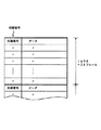
ここでは記録媒体(光ディスク)から再生された信号を想定している。この再生信号は、1セクタが複数フレームからなる(図2の例では1セクタが26フレーム)。そして1フレームは、同期信号としての同期番号とデータ領域からなり、同期番号は、少なくとも3個以上連続したときの数値が1セクタ内ではすべて異なる数値となるように組合わせ設定されている(図3参照)。即ち、図3に示すように同期番号は、フレーム番号0、1、2、3、4…の若い順に0、5、1、5、2、5、3、5、4…とういうふうに割り付けられている。ここで、同期番号の組合わせを見るとわかるように、3つあるは4つ連続して同期番号を組合わせてその数値をみると、1セクタ内では、同じ数値が存在しないように同期番号が割り付けてられている。したがって、各フレームの数値内容によりそのフレーム番号を認識することができるようになっている。
【0009】
図1に戻って説明する。上記のように取決めされた信号が入力端子100に入力する。この入力信号は、同期番号検出部101に入力される。同期番号検出部101で検出された同期番号は、フレーム番号検出部102に入力される。フレーム番号検出部102では、入力する同期番号を連続して3つあるいは4つを組合わせて図3に示した数値を生成し、この数値からフレーム番号を決定し、検出フレーム番号として出力する。同期番号の組合わせが「470」であればフレーム番号「0」、「705」であればフレーム番号「1」、「051」であればフレーム番号「2」というふうにフレーム番号を出力する。このフレーム番号を検出フレーム番号とする。
【0010】
また、入力信号は同期信号検出部103にも入力されている。この同期信号検出部103は、同期番号の内容には関わりなく、同期信号としての同期番号の入力タイミングを検出して、同期信号を出力する。同期信号は、フレーム番号出力部104に供給される。フレーム番号出力部104は、同期信号が入力するたびに例えば26でリセットされるカウンタをアップ制御し、予想フレーム番号を生成している。
【0011】
予想フレーム番号は、修正判定部105に入力される。修正判定部105は、予想フレーム番号と検出フレーム番号とを比較し、両者が一致するかどうかを判定している。修正判定部105は、予想フレーム番号と検出フレーム番号とが一致する場合には、修正指示信号として例えば“0”を出力する。このときはフレーム番号出力部104は、予想フレーム番号を出力フレーム番号として出力する。逆に、不一致であり、かつ検出フレーム番号の特性が所定の条件を満足した場合は、修正判定部105は、修正指示信号として“1”を出力する。このときはフレーム番号出力は、予想フレーム番号を修正して出力する、つまり、フレーム番号検出部102から出力されている検出フレーム番号を取り込み、これを出力フレーム番号として出力し、また、この検出フレーム番号に基づいて次の予想フレーム番号を生成するようになる。
【0012】
ここで修正判定部105が修正指示をフレーム番号出力部104に与える条件としては以下のような条件がある。
図4(A)と図4(B)にはそれぞれ修正判定部105の構成例を具体的に示している。
【0013】
図4(A)の修正判定部105とその動作を説明する。
図4(A)において、検出フレーム番号は、不一致判定部201と連続性検出部202に入力される。不一致判定部201は、検出フレーム番号と予想フレーム番号とを比較し両者が不一致のときに論理1を出力する。連続性検出部202は、検出フレーム番号が連続しているかどうかを検出するもので、例えば2フレーム、つまり2回連続しているときは論理1を出力する。アンド回路203は2つの入力が論理1のとき修正指示信号を出力する。したがって、アンド回路203からは、予想フレーム番号と検出フレーム番号とが不一致であり、かつ検出フレーム番号が2回連続した場合に修正指示信号である論理1が出力される。
【0014】
このことは、次のようなことを意味する。例え予想フレーム番号と検出フレーム番号との不一致が検出された場合であっても、検出フレーム番号の連続性がないことは、検出フレーム番号のエラー若しくは傷によるエラーによるもので一過性のものであったということである。次に、予想フレーム番号と検出フレーム番号との不一致が検出され、かつ、検出フレーム番号の連続性が存在したということは、検出フレーム番号が正しいということである。検出フレーム番号が正しく、予想フレーム番号が誤りということは、予想に誤差あるいは誤動作があった、若しくは特殊再生等により再生場所が変わったということがいえる。
【0015】
図5の(A)には、図4(A)の修正判定部105の動作を示すタイミングチャートを示している。同期番号が左側から0、5、1、5、2、5、3、5、1…と続いているが1はエラーであり本来ならば4のはずである(図3のテーブルを参照)。しかしエラー1の次に5、1、6、…と続き本来のコースに戻っている。つまり検出フレーム番号に連続性がないということである。このような場合は、修正指示信号は得られない。このために、出力フレーム番号は安定して連続している。
【0016】
上記の説明では、検出フレーム番号が2回連続した場合に修正指示信号を出力するとしたが、これに限定されるものではなく、3回あるいは4回連続した場合に修正指示信号を出力するようにしてもい。例えば、古いディスク等のように傷や誇りが多いようなディスクを再生する場合は、この連続検出回数を可変できるようにしてもよい。つまり連続検出部202に変更値を供給できるようにしてもよい。
【0017】
図5(B)には、修正判定部105において仮に連続性検出部202がなかった場合を想定しての動作タイミングチャートを示している。連続性検出部202がないと、修正指示信号がたびたび出力されることになり、出力フレーム番号がそのたびに変化し、誤動作の要因を作り出すことになる。
【0018】
図4(B)の修正判定部105とその動作を説明する。
図4(B)において、検出フレーム番号は、不一致判定部211と差分検出部212に入力される。不一致判定部211は、検出フレーム番号と予想フレーム番号とを比較し両者が不一致のときに論理1を出力する。差分検出部212は、検出フレーム番号と予想フレーム番号との差分を演算し両者の差が、例えば2以内(0、1、2)のとき論理1を出力する。アンド回路213は両入力が1のとき修正指示信号を出力する。したがって、アンド回路213からは、予想フレーム番号と検出フレーム番号とが不一致であり、かつ検出フレーム番号と予想フレーム番号の差が2以下であるときに修正指示信号である論理1が出力される。
【0019】
このことは、次のようなことを意味する。例え予想フレーム番号と検出フレーム番号との不一致が検出された場合であっても、検出フレーム番号と予想フレーム番号との差が大きい場合には、検出フレーム番号のエラー若しくは傷によるエラーによるもので一過性のものであったということである。次に、予想フレーム番号と検出フレーム番号との不一致が検出され、かつ、検出フレーム番号と予想フレーム番号との差が小さいということは比較的、検出フレーム番号が正しいということである。
【0020】
図6には、図4(B)の修正判定部105の動作を示すフローチャートを示している。同期番号が左側から0、5、1、5、2、5、3、5、1…と続いているが1はエラーであり本来ならば4のはずである(図3のテーブルを参照)。しかしエラー1の次に5、1、6…と続き本来のコースに戻っている。エラー1の次のフレームの同期番号5のときの検出フレーム番号は、3であり、予想フレーム番号は9であるから両者の差は大きい。このようなことは通常再生状態においては有り得ないことであるから修正指示信号は出力しないようになっている。
【0021】
上記の説明では、検出フレーム番号と予想フレーム番号が不一致であり、両者の差が2以内のときにとしたがこの数は限定されるものではなく、3以内、4以内としてもよい。この数を選定することにより、特殊再生等のときにジャンプするフレーム数に許容範囲を与えることができる。数が大きくなればそれだけフレームが離れて再生されても許容するということである。つまり差分検出部212に変更値を入力できるように構成してもよい。
【0022】
上記の説明は、連続する同期番号の3つを組合わせた3桁数値の内容を用いたが、これに限定されるものではない。
図3に示したように、連続する同期番号の4つを組合わせた内容をみても、1つのセクタ内(26フレーム内)には同一の4桁数値が存在しない。したがってこの4桁数値を用いても同様な効果が得られる。
【0023】
図7は、4桁数値を用いた場合に修正指示信号が発生したときの動作を説明するためのタイミングチャートを示している。
同期番号が左側から0、5、1、5、2、5、3、5、1、…と続いているが1はエラーであり本来ならば4のはずである(図3のテーブルを参照)。しかしエラー1の次に5、1、6…と続き本来のコースに戻っている。エラー1が発生したときの検出フレーム番号は、4桁数値で「5351」であるがこのような検出フレーム番号は、図3のテーブルには存在しない。このような場合は、予想フレーム番号8がそのまま出力フレーム番号となるように設定されている。次のフレームでは、4桁数値で「3515」となり、この数値も図3のテーブルには存在しない。従って、このときも予想フレーム番号9がそのまま出力フレーム番号となる。
【0024】
次のフレームでは、4桁数値で「5151」となり、この数値も図3のテーブルには存在しない。従って、このときも予想フレーム番号10がそのまま出力フレーム番号となる。
【0025】
次のフレームでは、4桁数値で「1516」となり、この数値は図3のテーブルには存在しない。従って、このときは予想フレーム番号11(先の13の次の番号)がそのまま出力フレーム番号となる。
【0026】
さらに次のフレームでは、4桁数値で「5162」となり、これは図3のテーブルにはフレーム番号12として存在する。よってこのときはフレーム番号検出部からフレーム番号12が出力され、予想フレーム番号12と比較される。このときは、一致となり、予想フレーム番号12がそのまま出力フレーム番号となる。
【0027】
上記したように同期番号の4連続数を利用した4桁数値を用いても、出力フレーム番号を安定化することができ、さらに図4に示す連続検出部や差分検出部を用いると一層、出力フレーム番号の安定性を得ることができる。
【0028】
上述した実施の形態は、ハードウエアにより構成されているが、この発明の方法は、ソフトウエアにより実現できることは勿論である。
図8は、図4(A)と図5(A)に示した機能及び動作を実現することができるフローチャートを示す。また図9は、図4(B)と図6に示した機能及び動作を実現することができるフローチャートを示す。図8のフローチャートを説明する。入力信号から同期番号が抽出されて蓄積され、図3に示したような複数桁の数値が作成される(ステップA1、A2)。そして複数桁の数値が図3に示したテーブルに存在するかどうかの判定が行われ、存在する場合には対応するフレーム番号を検出フレーム番号とする(ステップA4)。もし存在しない場合は予想フレーム番号を出力フレーム番号として出力する(ステップA6)。次に検出不えーむ番号が得られた場合は、その検出フレーム番号と予想フレーム番号を比較し、一致するかどうかの判定を行い(ステップA5)、一致した場合は、予想フレーム番号を出力フレーム番号として出力する(ステップA6)。ステップA5で不一致の場合は、検出フレーム番号に連続性があるかどうかの判定を行い、連続性がない場合は、誤ったフレーム番号が突発的に生じたものと判定し、ステップA6移行し、予想フレーム番号を出力フレーム番号として出力する(ステップA7)。しかし、ステップA7で検出フレーム番号に連続性があった場合は、最新の検出フレーム番号を予想フレーム番号に置き換えるとともに、出力フレーム番号して出力する(ステップA8)。
【0029】
図9のフローチャートを説明する。このフローチャートは、図8のフローチャートに比べて、ステップA5で不一致が得られたときの処理が異なる。つまり、検出フレーム番号と予想フレーム番号との差がとられ、その差が所定の範囲ないであるかどうかの判定が行われる(ステップA11)。所定の範囲内であれば、最新の検出フレーム番号を予想フレーム番号に置き換えるとともに、出力フレーム番号して出力する(ステップA12)。しかし所定の範囲を越えていれば、誤ったフレーム番号が突発的に生じたものと判定し、ステップA6移行し、予想フレーム番号を出力フレーム番号として出力する。
【0030】
【発明の効果】
以上説明したようにこの発明によれば、再生位置の認識をフレーム単位で確実に得られるようにし、特に、フレーム番号の修正機能を信頼性の高いものとすることができる。
【図面の簡単な説明】
【図1】この発明の一実施の形態を示す図。
【図2】図1の装置に入力する信号のフォーマット説明図。
【図3】図1の装置に入力する信号のフレーム番号と同期番号の説明図。
【図4】図1の修正判定部の構成例を示す図。
【図5】図4(A)の判定部の動作を説明するために示したタイミングチャート。
【図6】図4(B)の判定部の動作を説明するために示したタイミングチャート。
【図7】さらに別の判定部の動作を説明するために示したタイミングチャート。
【図8】この発明の装置の動作例を説明するために示したフローチャート。
【図9】この発明の装置の別の動作例を説明するために示したフローチャート。
【符号の説明】
101…同期番号検出部、102…フレーム番号検出部、103…同期信号検出部、104…フレーム番号出力部、105…修正判定部、201、211…不一致判定部、202…連続性検出部、203、213…アンド回路、212…差分検出部。[0001]
[Industrial application fields]
In the present invention, when recording video, audio or various information on a recording medium such as an optical disk, or when reproducing recorded information, a synchronization signal and a frame number necessary for data management are recorded and reproduced. The present invention relates to an apparatus and a method for correcting a frame number effective for the above.
[0002]
[Prior art]
In recent years, optical discs capable of recording and reproducing information using a laser beam as a medium have been developed. Here, various proposals have been made as a format for recording information on an optical disc. In any case, a synchronization signal is indispensable. When reproducing such an optical disc, the synchronization signal is reproduced, the synchronization signal is counted, and the frame is determined based on the count value. That is, the frame is detected by counting the synchronization signal. However, if the disk rotates abnormally, the length of the frame becomes longer or shorter. Then, a synchronization signal count error or the like occurs, and it is unclear which frame in the sector is being reproduced, and all the data reproduced here becomes an error.
[0003]
[Problems to be solved by the invention]
As described above, the frame is detected by detecting the synchronization signal. However, when the disk rotates abnormally, a synchronization signal count error occurs when the length of the frame becomes longer or shorter. Then, it may be unclear which frame in the sector is being reproduced. In such a case, all the data reproduced here will be an error.
[0004]
Accordingly, the present invention provides a frame number correcting apparatus and method that make it possible to reliably recognize the playback position in units of frames, in particular, develop a frame number correcting function, and make its performance highly reliable. It is intended to do.
[0005]
[Means for Solving the Problems]
One sector is composed of a plurality of frames, one frame is composed of a synchronization number and a data area as a synchronization signal, and the synchronization numbers are set so that the numbers when at least three or more are consecutive are all different numbers within one sector. An input unit to which information that is set together and is configured to identify the continuous frame number of each successive frame in the one sector by the numerical value is input, and a plurality of synchronization numbers are detected by detecting the synchronization number A frame number detection means for generating a detection frame number, a synchronization signal generation means for generating a synchronization signal by capturing the synchronization number as a synchronization signal, and a frame number generation for generating an expected frame number at the timing of the synchronization signal Means for comparing the predicted frame number with the detected frame number, Output as a force frame number, a mismatch, and only when the state of the detection frame number satisfies the predetermined condition, in which and a correction means for outputting corrected the expected frame number.
[0006]
The predetermined condition is a case where the detected frame numbers are, for example, two consecutive frames. If it is not continuous, no correction is made. The predetermined condition is that the difference between the detected frame number and the predicted frame number is within ± 2 frames, for example. When the difference between the detected frame number and the predicted frame number is large, correction is not performed. By the above means, the output frame number becomes highly reliable.
[0007]
Embodiment
Embodiments of the present invention will be described below with reference to the drawings.
FIG. 1 is a diagram showing an embodiment of the present invention, and FIG. 2 is an explanatory diagram of an input signal at the input unit of FIG. This input signal is of the type shown in Japanese Patent Application No. 7-88672, for example. FIG. 3 is a diagram showing a combination of three frame numbers of the input signal and four synchronization number combinations of synchronization numbers.
[0008]
Here, a signal reproduced from a recording medium (optical disk) is assumed. In this reproduction signal, one sector is composed of a plurality of frames (in the example of FIG. 2, one sector is 26 frames). One frame is composed of a synchronization number as a synchronization signal and a data area, and the synchronization numbers are set in combination so that the numerical values when at least three or more consecutive numbers are different within one sector (see FIG. 3). That is, as shown in FIG. 3, the synchronization numbers are assigned in the order of 0, 5, 1, 5, 2, 5, 3, 5, 4 ... in ascending order of
[0009]
Returning to FIG. The signal determined as described above is input to the
[0010]
The input signal is also input to the synchronization
[0011]
The predicted frame number is input to the
[0012]
Here, conditions for the
FIG. 4A and FIG. 4B each specifically show a configuration example of the
[0013]
The
In FIG. 4A, the detected frame number is input to the
[0014]
This means the following. Even if a mismatch between the expected frame number and the detected frame number is detected, the lack of continuity in the detected frame number is due to an error in the detected frame number or an error due to a flaw. It was that there was. Next, when a mismatch between the predicted frame number and the detected frame number is detected and there is continuity of the detected frame number, the detected frame number is correct. If the detected frame number is correct and the predicted frame number is incorrect, it can be said that there is an error or malfunction in the prediction, or that the playback location has changed due to special playback or the like.
[0015]
FIG. 5A shows a timing chart showing the operation of the
[0016]
In the above description, the correction instruction signal is output when the detected frame number is continuous twice. However, the present invention is not limited to this, and the correction instruction signal is output when the detection frame number is continuous three or four times. Well. For example, when reproducing a disk with many scratches and pride, such as an old disk, the number of continuous detections may be variable. That is, the change value may be supplied to the continuous detection unit 202.
[0017]
FIG. 5B shows an operation timing chart assuming that there is no continuity detection unit 202 in the
[0018]
The
In FIG. 4B, the detected frame number is input to the mismatch determination unit 211 and the difference detection unit 212. The mismatch determination unit 211 compares the detected frame number with the expected frame number, and
[0019]
This means the following. Even if a mismatch between the predicted frame number and the detected frame number is detected, if the difference between the detected frame number and the predicted frame number is large, it may be due to an error in the detected frame number or an error due to a flaw. It was a temporary thing. Next, when a mismatch between the predicted frame number and the detected frame number is detected and the difference between the detected frame number and the predicted frame number is small, the detected frame number is relatively correct.
[0020]
FIG. 6 is a flowchart showing the operation of the
[0021]
In the above description, the detected frame number and the expected frame number do not match, and the difference between the two is within 2. However, this number is not limited and may be within 3 or within 4. By selecting this number, an allowable range can be given to the number of frames to be jumped during special reproduction or the like. The larger the number is, the more frames can be played back apart. That is, it may be configured such that a change value can be input to the difference detection unit 212.
[0022]
In the above description, the content of a three-digit numerical value combining three consecutive synchronization numbers is used, but the present invention is not limited to this.
As shown in FIG. 3, even when looking at the contents of combining four consecutive synchronization numbers, the same four-digit value does not exist in one sector (26 frames). Therefore, the same effect can be obtained even if this 4-digit numerical value is used.
[0023]
FIG. 7 shows a timing chart for explaining the operation when a correction instruction signal is generated when a 4-digit numerical value is used.
The synchronization number continues from 0, 5, 1, 5, 2, 5, 3, 5, 1,... From the left, but 1 is an error and should be 4 (see the table in FIG. 3). . However, after
[0024]
In the next frame, the 4-digit numerical value is “5151”, and this numerical value does not exist in the table of FIG. Accordingly, at this time, the predicted
[0025]
In the next frame, the 4-digit numerical value is “1516”, and this numerical value does not exist in the table of FIG. Therefore, at this time, the predicted frame number 11 (the number next to the previous 13) becomes the output frame number as it is.
[0026]
In the next frame, the 4-digit numerical value is “5162”, which is present as
[0027]
As described above, the output frame number can be stabilized even if a 4-digit numerical value using the 4 consecutive numbers of the synchronization number is used. Further, if the continuous detection unit and the difference detection unit shown in FIG. The stability of the frame number can be obtained.
[0028]
Although the embodiment described above is configured by hardware, it is needless to say that the method of the present invention can be realized by software.
FIG. 8 shows a flowchart capable of realizing the functions and operations shown in FIGS. 4 (A) and 5 (A). FIG. 9 shows a flowchart capable of realizing the functions and operations shown in FIG. 4B and FIG. The flowchart of FIG. 8 will be described. A synchronization number is extracted from the input signal and stored, and a multi-digit numerical value as shown in FIG. 3 is created (steps A1 and A2). Then, it is determined whether or not a multi-digit numerical value exists in the table shown in FIG. 3, and if it exists, the corresponding frame number is set as the detected frame number (step A4). If not, the predicted frame number is output as the output frame number (step A6). Next, when a number that is not detected is obtained, the detected frame number is compared with the predicted frame number to determine whether or not they match (step A5). If they match, the predicted frame number is output as the output frame. It outputs as a number (step A6). If there is a mismatch in step A5, it is determined whether the detected frame number has continuity. If there is no continuity, it is determined that an erroneous frame number has occurred suddenly, and the process proceeds to step A6. The predicted frame number is output as an output frame number (step A7). However, if there is continuity in the detected frame numbers in step A7, the latest detected frame number is replaced with the predicted frame number, and the output frame number is output (step A8).
[0029]
The flowchart of FIG. 9 will be described. This flowchart differs from the flowchart of FIG. 8 in the processing when a mismatch is obtained in step A5. That is, the difference between the detected frame number and the predicted frame number is taken, and it is determined whether or not the difference is within a predetermined range (step A11). If it is within the predetermined range, the latest detected frame number is replaced with the predicted frame number, and the output frame number is output (step A12). However, if it exceeds the predetermined range, it is determined that an erroneous frame number has occurred suddenly, the process proceeds to step A6, and the predicted frame number is output as the output frame number.
[0030]
【The invention's effect】
As described above, according to the present invention, the reproduction position can be reliably recognized in units of frames, and in particular, the frame number correction function can be made highly reliable.
[Brief description of the drawings]
FIG. 1 is a diagram showing an embodiment of the present invention.
FIG. 2 is an explanatory diagram of a format of a signal input to the apparatus of FIG.
FIG. 3 is an explanatory diagram of a frame number and a synchronization number of a signal input to the apparatus of FIG.
4 is a diagram illustrating a configuration example of a correction determination unit in FIG. 1;
FIG. 5 is a timing chart shown for explaining the operation of the determination unit in FIG.
FIG. 6 is a timing chart shown for explaining the operation of the determination unit in FIG.
FIG. 7 is a timing chart for explaining the operation of another determination unit;
FIG. 8 is a flowchart shown for explaining an operation example of the apparatus of the present invention;
FIG. 9 is a flowchart shown for explaining another operation example of the apparatus of the present invention;
[Explanation of symbols]
DESCRIPTION OF SYMBOLS 101 ... Synchronization number detection part, 102 ... Frame number detection part, 103 ... Synchronization signal detection part, 104 ... Frame number output part, 105 ... Correction determination part, 201, 211 ... Mismatch determination part, 202 ... Continuity detection part, 203 213... AND circuit, 212.
Claims (6)
前記入力信号から前記同期番号を検出して複数の同期番号を組合わせ検出フレーム番号を生成するフレーム番号検出手段と、
前記入力信号の前記同期番号を同期信号として捕らえて同期信号を生成する同期信号生成手段と、
前記同期信号のタイミングで予想フレーム番号を発生するフレーム番号発生手段と、
前記予想フレーム番号と前記検出フレーム番号とを比較して、一致する場合には前記予想フレーム番号を出力フレーム番号として出力し、不一致であり、かつ前記検出フレーム番号の状態が所定の条件を満足している場合にのみ、前記予想フレーム番号を修正して出力する修正手段とを具備したことを特徴とするフレーム番号修正装置。One sector consists of a plurality of frames, one frame consists of a synchronization number as a synchronization signal and a data area, and the synchronization number is set so that one or more consecutive numerical values are all different values within one sector. An input unit that receives an input signal that can identify the consecutive frame number of each successive frame in the one sector by the numerical value;
Frame number detection means for detecting the synchronization number from the input signal and generating a detection frame number by combining a plurality of synchronization numbers;
Synchronization signal generating means for capturing the synchronization number of the input signal as a synchronization signal and generating a synchronization signal;
Frame number generating means for generating an expected frame number at the timing of the synchronization signal;
The predicted frame number and the detected frame number are compared, and if they match, the predicted frame number is output as an output frame number, which does not match, and the state of the detected frame number satisfies a predetermined condition A frame number correcting device, comprising: a correcting means for correcting and outputting the predicted frame number only when
前記予想フレーム番号と前記検出フレーム番号とが不一致であり、かつ、前記検出フレーム番号が、続くフレームにおいてもN個の連続性があるときに前記予想フレーム番号を最新の検出フレーム番号に修正して出力することを特徴とする請求項1記載のフレーム番号修正装置。The correcting means is
When the predicted frame number does not match the detected frame number, and the detected frame number has N continuity in the subsequent frames, the predicted frame number is corrected to the latest detected frame number. The frame number correcting apparatus according to claim 1, wherein the frame number correcting apparatus outputs the frame number.
前記予想フレーム番号と前記検出フレーム番号とが不一致であり、かつ、前記検出フレーム番号と前記予想フレーム番号との差がN個以内である場合に、前記予想フレーム番号を最新の検出フレーム番号に修正して出力することを特徴とする請求項1記載のフレーム番号修正装置。The correcting means is
When the predicted frame number does not match the detected frame number, and the difference between the detected frame number and the predicted frame number is within N, the predicted frame number is corrected to the latest detected frame number. 2. The frame number correcting apparatus according to claim 1, wherein the frame number correcting apparatus outputs the frame number.
前記入力信号から前記同期番号を検出して複数の同期番号を蓄積して組合わせ検出フレーム番号を生成し、
前記入力信号の前記同期番号を同期信号として捕らえて同期信号を生成して前記同期信号のタイミングで予想フレーム番号を発生し、
前記予想フレーム番号と前記検出フレーム番号とを比較して、一致する場合には前記予想フレーム番号を出力フレーム番号として出力し、
前記予想フレーム番号と前記検出フレーム番号とを比較して、不一致の場合はは、前記検出フレーム番号と次の検出フレーム番号が連続しているかどうかを判定し、
前記判定結果が不連続の場合は、前記予想フレーム番号を出力フレーム番号として出力し、連続している場合は、前記予想フレーム番号を最新の検出フレーム番号に修正するとともにこの最新の検出フレーム番号を出力フレーム番号として出力するようにしたことを特徴とするフレーム番号修正方法。One sector is composed of a plurality of frames, and one frame is composed of a synchronization number as a synchronization signal and a data area, and the synchronization numbers are set so that the numbers when at least three or more consecutive numbers are different in one sector Using an input signal that is set to match and can identify the consecutive frame number of each successive frame in the one sector by the numerical value,
Detecting the synchronization number from the input signal and accumulating a plurality of synchronization numbers to generate a combination detection frame number;
Capture the synchronization number of the input signal as a synchronization signal and generate a synchronization signal to generate an expected frame number at the timing of the synchronization signal;
The predicted frame number and the detected frame number are compared, and if they match, the predicted frame number is output as an output frame number,
Compare the expected frame number and the detected frame number, if there is a mismatch, determine whether the detected frame number and the next detected frame number are consecutive,
When the determination result is discontinuous, the predicted frame number is output as an output frame number, and when it is continuous, the predicted frame number is corrected to the latest detected frame number and the latest detected frame number is changed. A frame number correction method characterized in that an output frame number is output.
前記入力信号から前記同期番号を検出して複数の同期番号を蓄積して組合わせ検出フレーム番号を生成し、
前記入力信号の前記同期番号を同期信号として捕らえて同期信号を生成して前記同期信号のタイミングで予想フレーム番号を発生し、
前記予想フレーム番号と前記検出フレーム番号とを比較して、一致する場合には前記予想フレーム番号を出力フレーム番号として出力し、
前記予想フレーム番号と前記検出フレーム番号との差を検出し、差が所定値以内であるかどうかを判定し、
前記判定結果が所定値外の場合は、前記予想フレーム番号を出力フレーム番号として出力し、所定値以内の場合は、前記予想フレーム番号を最新の検出フレーム番号に修正するとともにこの最新の検出フレーム番号を出力フレーム番号として出力するようにしたことを特徴とするフレーム番号修正方法。One sector is composed of a plurality of frames, one frame is composed of a synchronization number and a data area as a synchronization signal, and the synchronization numbers are set so that the numbers when at least three or more are consecutive are all different numbers within one sector. Using an input signal that is set to match and can identify the consecutive frame number of each successive frame in the one sector by the numerical value,
Detecting the synchronization number from the input signal and accumulating a plurality of synchronization numbers to generate a combination detection frame number;
Capture the synchronization number of the input signal as a synchronization signal and generate a synchronization signal to generate an expected frame number at the timing of the synchronization signal;
The predicted frame number and the detected frame number are compared, and if they match, the predicted frame number is output as an output frame number,
Detecting a difference between the expected frame number and the detected frame number, and determining whether the difference is within a predetermined value;
When the determination result is outside the predetermined value, the predicted frame number is output as an output frame number. When the determination result is within the predetermined value, the predicted frame number is corrected to the latest detected frame number and the latest detected frame number is output. Is output as an output frame number.
前記入力信号から前記同期番号を検出して複数の同期番号を組合わせて検出フレーム番号を生成するフレーム番号検出手段と、
前記前記入力信号の前記同期番号を同期信号として捕らえて同期信号を生成する同期信号生成手段と、
前記同期信号のタイミングで予想フレーム番号を発生するフレーム番号発生手段と、
前記予想フレーム番号と前記検出フレーム番号とを比較して、一致する場合には前記予想フレーム番号を出力フレーム番号として出力する手段と、
前記予想フレーム番号と前記検出フレーム番号とを比較して、不一致であり、かつ、前記検出フレーム番号と前記予想フレーム番号との差がN個以内である場合に、前記予想フレーム番号を最新の検出フレーム番号に修正して出力する手段とを具備したことを特徴とするフレーム番号修正装置。One sector is composed of a plurality of frames, one frame is composed of a synchronization number and a data area as a synchronization signal, and the synchronization numbers are set so that the numbers when at least three or more are consecutive are all different numbers within one sector. And an input unit that receives an input signal that is set to be combined and can identify the continuous frame number of each continuous frame in the one sector by the numerical value;
Frame number detection means for detecting the synchronization number from the input signal and generating a detection frame number by combining a plurality of synchronization numbers;
Synchronization signal generating means for capturing the synchronization number of the input signal as a synchronization signal and generating a synchronization signal;
Frame number generating means for generating an expected frame number at the timing of the synchronization signal;
Means for comparing the predicted frame number with the detected frame number and outputting the predicted frame number as an output frame number if they match,
The predicted frame number is compared with the detected frame number, and the latest detected frame number is detected when there is a mismatch and the difference between the detected frame number and the predicted frame number is N or less. And a means for correcting the frame number and outputting it.
Priority Applications (1)
| Application Number | Priority Date | Filing Date | Title |
|---|---|---|---|
| JP28600195A JP3702015B2 (en) | 1995-11-02 | 1995-11-02 | Frame number correcting apparatus and method |
Applications Claiming Priority (1)
| Application Number | Priority Date | Filing Date | Title |
|---|---|---|---|
| JP28600195A JP3702015B2 (en) | 1995-11-02 | 1995-11-02 | Frame number correcting apparatus and method |
Publications (2)
| Publication Number | Publication Date |
|---|---|
| JPH09128907A JPH09128907A (en) | 1997-05-16 |
| JP3702015B2 true JP3702015B2 (en) | 2005-10-05 |
Family
ID=17698728
Family Applications (1)
| Application Number | Title | Priority Date | Filing Date |
|---|---|---|---|
| JP28600195A Expired - Lifetime JP3702015B2 (en) | 1995-11-02 | 1995-11-02 | Frame number correcting apparatus and method |
Country Status (1)
| Country | Link |
|---|---|
| JP (1) | JP3702015B2 (en) |
Families Citing this family (7)
| Publication number | Priority date | Publication date | Assignee | Title |
|---|---|---|---|---|
| JP3729362B2 (en) * | 1996-07-15 | 2005-12-21 | ソニー株式会社 | Recording medium reproducing apparatus and recording medium reproducing method |
| JP3042607B2 (en) | 1997-06-13 | 2000-05-15 | 日本電気株式会社 | Sync detection circuit |
| EP1571665A3 (en) * | 2002-06-05 | 2010-04-07 | Lg Electronics Inc. | Recording medium with a linking area including dummy data thereon and apparatus and methods for forming, recording, and reproducing the recording medium |
| KR100576160B1 (en) * | 2002-12-11 | 2006-05-03 | 엘지전자 주식회사 | Method and apparatus for discriminating record position of high density optical disc |
| JP2004253099A (en) | 2003-02-21 | 2004-09-09 | Toshiba Corp | Sync frame structure, information storage medium, information recording method, information reproducing method, and information reproducing device |
| KR100524992B1 (en) * | 2003-11-11 | 2005-10-31 | 삼성전자주식회사 | Disk player for allotting pointers to CD frames and storing pointers and frames to memory and method for controlling reproducing data of disk player |
| CN101297366A (en) * | 2005-10-28 | 2008-10-29 | 松下电器产业株式会社 | Information reproduction device, information reproduction method, and information reproduction program |
-
1995
- 1995-11-02 JP JP28600195A patent/JP3702015B2/en not_active Expired - Lifetime
Also Published As
| Publication number | Publication date |
|---|---|
| JPH09128907A (en) | 1997-05-16 |
Similar Documents
| Publication | Publication Date | Title |
|---|---|---|
| JP2730024B2 (en) | Method and apparatus for recording / reproducing digital information | |
| JPS6412143B2 (en) | ||
| JP3702015B2 (en) | Frame number correcting apparatus and method | |
| KR100206330B1 (en) | Synchronization data recovery apparatus and method for digital video disk reproduction system | |
| JP4618760B2 (en) | Optical disc reproducing apparatus and data reproducing method thereof | |
| US7542390B2 (en) | Method for sampling optical disc data and apparatus thereof | |
| JPS6016028B2 (en) | time code reader | |
| US6690630B1 (en) | Compact disc decoder and method for correcting address errors in header data based on an input error flag | |
| JPS61190755A (en) | Address circuit | |
| JP3042607B2 (en) | Sync detection circuit | |
| US5995307A (en) | Method of forcibly judging a sector synchronous signal for a disk reproducing apparatus | |
| JPS60101766A (en) | Address detection system | |
| US6209117B1 (en) | Method for canceling abnormal synchronization signal | |
| JPH0344394B2 (en) | ||
| KR100207242B1 (en) | Variable synchronization detecting method for video compact disc player | |
| KR100190093B1 (en) | Apparatus for generating block address for block data serially transmitted | |
| KR960035580A (en) | Variable Synchronization Pattern Detection Apparatus and Method of Digital Recording and Reproduction System | |
| JPH07272415A (en) | Recording medium and reproducer thereof | |
| JPH08289249A (en) | Recording medium and its synchronizing signal arranging device, reproducing device and method | |
| JP3519273B2 (en) | Digital recording and playback device | |
| JPH10134515A (en) | Synchronous circuit | |
| KR100324762B1 (en) | Reproducing method for digital signal recording and reproducing apparatus | |
| KR100188662B1 (en) | Audio error correction apparatus of digital video type recorder | |
| JPH0411945B2 (en) | ||
| JP2004048614A (en) | Video image recorder |
Legal Events
| Date | Code | Title | Description |
|---|---|---|---|
| A977 | Report on retrieval |
Free format text: JAPANESE INTERMEDIATE CODE: A971007 Effective date: 20050705 |
|
| TRDD | Decision of grant or rejection written | ||
| A01 | Written decision to grant a patent or to grant a registration (utility model) |
Free format text: JAPANESE INTERMEDIATE CODE: A01 Effective date: 20050712 |
|
| A61 | First payment of annual fees (during grant procedure) |
Free format text: JAPANESE INTERMEDIATE CODE: A61 Effective date: 20050715 |
|
| R150 | Certificate of patent or registration of utility model |
Free format text: JAPANESE INTERMEDIATE CODE: R150 |
|
| FPAY | Renewal fee payment (event date is renewal date of database) |
Free format text: PAYMENT UNTIL: 20090722 Year of fee payment: 4 |
|
| FPAY | Renewal fee payment (event date is renewal date of database) |
Free format text: PAYMENT UNTIL: 20090722 Year of fee payment: 4 |
|
| FPAY | Renewal fee payment (event date is renewal date of database) |
Free format text: PAYMENT UNTIL: 20100722 Year of fee payment: 5 |
|
| FPAY | Renewal fee payment (event date is renewal date of database) |
Free format text: PAYMENT UNTIL: 20110722 Year of fee payment: 6 |
|
| FPAY | Renewal fee payment (event date is renewal date of database) |
Free format text: PAYMENT UNTIL: 20120722 Year of fee payment: 7 |
|
| FPAY | Renewal fee payment (event date is renewal date of database) |
Free format text: PAYMENT UNTIL: 20130722 Year of fee payment: 8 |
|
| S531 | Written request for registration of change of domicile |
Free format text: JAPANESE INTERMEDIATE CODE: R313531 |
|
| R350 | Written notification of registration of transfer |
Free format text: JAPANESE INTERMEDIATE CODE: R350 |
|
| S111 | Request for change of ownership or part of ownership |
Free format text: JAPANESE INTERMEDIATE CODE: R313117 |
|
| R350 | Written notification of registration of transfer |
Free format text: JAPANESE INTERMEDIATE CODE: R350 |
|
| S111 | Request for change of ownership or part of ownership |
Free format text: JAPANESE INTERMEDIATE CODE: R313113 |
|
| R250 | Receipt of annual fees |
Free format text: JAPANESE INTERMEDIATE CODE: R250 |
|
| R350 | Written notification of registration of transfer |
Free format text: JAPANESE INTERMEDIATE CODE: R350 |
|
| R250 | Receipt of annual fees |
Free format text: JAPANESE INTERMEDIATE CODE: R250 |
|
| EXPY | Cancellation because of completion of term |