JP3696477B2 - Access system - Google Patents
Access system Download PDFInfo
- Publication number
- JP3696477B2 JP3696477B2 JP2000105130A JP2000105130A JP3696477B2 JP 3696477 B2 JP3696477 B2 JP 3696477B2 JP 2000105130 A JP2000105130 A JP 2000105130A JP 2000105130 A JP2000105130 A JP 2000105130A JP 3696477 B2 JP3696477 B2 JP 3696477B2
- Authority
- JP
- Japan
- Prior art keywords
- information
- access
- unit
- medium
- tag
- Prior art date
- Legal status (The legal status is an assumption and is not a legal conclusion. Google has not performed a legal analysis and makes no representation as to the accuracy of the status listed.)
- Expired - Fee Related
Links
Images


Description
【0001】
【発明の属する技術分野】
本発明は、電波を用いて非接触に読み書き可能な情報記憶媒体及び前記情報記憶媒体との間で情報を送受信するアクセス技術に関する。
【0002】
【従来の技術】
物品と情報とを一体として管理する技術が提案されている。例えば、特開平11−120308号公報によると、製品機器に関する履歴情報が製品と一体的に記憶されるようにした履歴情報記憶装置が開示されている。
【0003】
【発明が解決しようとする課題】
しかしながら、物品と情報とを一体とした管理において、さらに多様な利用の要望がある。
本発明は、上記の要望に鑑み、さらに多様な利用が可能な情報記憶媒体、アクセス装置、アクセスシステム及びアクセスプログラムを記録している記録媒体を提供することを目的とする。
【0004】
【課題を解決するための手段】
上記目的を達成するために、本発明は、電波を用いて非接触に読み書き可能な情報記憶媒体と前記情報記憶媒体との間で電波を用いて情報を送受信するアクセス装置とから構成されるアクセスシステムであって、前記アクセス装置は、それぞれ異なる周波数の電波により情報を送信する複数の装置送信手段と、前記複数の周波数とそれぞれ同一の周波数の電波により送信される情報を受信する複数の装置受信手段と、前記複数の装置送信手段に対して、一の時間帯において前記情報記憶媒体に対するアクセスの開始を示すアクセス要求情報を送信するように制御する装置制御手段とを備え、前記情報記憶媒体は、前記アクセス装置の送信する周波数のうちの1と同一の周波数の電波により前記アクセス要求情報を受信する媒体受信手段と、前記受信する周波数と同一の周波数の電波により情報を送信する媒体送信手段と、前記アクセス要求情報を受信すると、前記アクセス要求情報に対する応答を示すアクセス応答情報を送信するように、前記媒体送信手段に対して制御する媒体制御手段とを備えることを特徴とする。
【0005】
また、本発明は、形象が印刷された印刷媒体と、電波を用いて非接触に読み書き可能な情報記憶媒体と、前記情報記憶媒体との間で電波を用いて情報を送受信するアクセス装置とから構成されるアクセスシステムであって、前記印刷媒体の面上に第1情報を表示する形象が印刷され、前記アクセス装置は、光読出手段と、装置送信手段と、装置受信手段と、照合手段とから構成され、前記情報記憶媒体は、前記情報記憶媒体に関連する第1媒体情報を記憶している情報記憶手段と、媒体受信手段と、媒体送信手段とから構成され、前記光読出手段は、光を用いて前記印刷媒体面上に印刷されている形象を読み出し、読み出した形象に基づいて第2情報を生成し、前記装置送信手段は、アクセス要求を電波を用いて送信し、前記媒体受信手段は、アクセス要求を電波を用いて受信し、前記媒体送信手段は、前記情報記憶手段から第1媒体情報を読み出し、読み出した第1媒体情報を電波を用いて送信し、前記装置受信手段は、電波を用いて送信された第1媒体情報を受信し、前記照合手段は、受信した前記第1媒体情報と生成された前記第2情報とが一致しているか否かを判断し、前記アクセス装置と前記情報記憶媒体とは、一致すると判断される場合に、第1情報と第1媒体情報とが同一であるとみなして、前記アクセス装置と前記情報記憶媒体との間で情報を送受信することを特徴とする。
【0006】
また、本発明は、電波を用いて非接触に読み書き可能な情報記憶媒体と、前記情報記憶媒体から電波を用いて情報を読み出して印刷媒体上に印刷する印刷装置とから構成される印刷システムであって、前記印刷装置は、装置送信手段と、装置受信手段と、形象生成手段と、印刷手段とから構成され、前記情報記憶媒体は、前記情報記憶媒体に関する媒体情報を記憶している情報記憶手段と、媒体受信手段と、媒体送信手段とから構成され、前記装置送信手段は、アクセス要求を電波を用いて送信し、前記媒体受信手段は、アクセス要求を電波を用いて受信し、前記媒体送信手段は、前記情報記憶手段から媒体情報を読み出し、読み出した前記媒体情報を電波を用いて送信し、前記装置受信手段は、電波を用いて送信された前記媒体情報を受信し、前記形象生成手段は、受信した前記媒体情報に基づいて形象を生成し、前記印刷手段は、生成された形象を印刷媒体上に印刷することを特徴とする。
【0007】
また、本発明は、電波を用いて非接触に読み書き可能な情報記憶媒体と、前記情報記憶媒体との間で情報を送受信する移動電話機と、前記移動電話機との間で公衆回線網を介して通信を行うセンタ装置とから構成されるアクセス通信システムであって、前記情報記憶媒体は、前記センタ装置の電話番号を記憶している記憶手段と、前記電話番号を電波を用いて送信する送信手段とを備え、前記移動電話機は、電波を用いて前記電話番号を受信する受信手段と、前記センタ装置との間で前記公衆回線網を介して回線を接続するために、受信した前記電話番号に基づいて発呼する発呼手段と、回線の接続されたセンタ装置との間で通信を行う第1通信手段とを備え、前記センタ装置は、回線の接続された前記移動電話機との間で通信を行う第2通信手段を備え、前記移動電話機と前記センタ装置との間で回線が接続された場合に、前記センタ装置と前記情報記憶媒体との間で通信を行うことを特徴とする。
【0008】
また、本発明は、光を用いて情報の読み出し又は書込みが可能な光ディスク媒体であって、半導体メモリから構成される情報記憶手段と、電波を用いてアクセス要求を受信する受信手段と、受信したアクセス要求に応じて前記情報記憶手段にアクセスし、アクセス結果情報を生成するアクセス手段と、生成された前記アクセス結果情報を電波を用いて送信する送信手段とを備えることを特徴とする。
【0009】
また、本発明は、前記光ディスク媒体から情報を読み出して再生する光ディスク媒体再生装置であって、前記光ディスク媒体は、光を用いて情報の読み書きが可能な光記憶手段を有し、前記情報記憶手段は、光記憶手段に記憶されている情報の再生が許可されるか否かを示す権利情報を記憶しており、前記アクセス手段は、前記権利情報を含むアクセス結果情報を生成し、前記光ディスク媒体再生装置は、電波を用いてアクセス要求を送信する送信手段と、アクセス要求に応じたアクセス結果情報を電波を用いて受信する受信手段と、アクセス結果情報に含まれる権利情報に基づいて、情報の再生が許可されるか否かを判断する判断手段と、情報の再生が許可される場合に、前記光記憶手段から情報を読み出して再生する再生手段とを備えることを特徴とする。
【0010】
また、本発明は、電波を用いて非接触に読み書き可能な情報記憶媒体であって、情報を記憶する領域を有する情報記憶手段と、複数種類の周波数の電波のいずれかを用いて前記情報記憶手段へのアクセス指示を要求するアクセス要求を受信する媒体受信手段と、受信したアクセス要求に基づいて、前記情報記憶手段にアクセスし、アクセス結果情報を生成するアクセス手段と、生成された前記アクセス結果情報を前記媒体受信手段により用いられた周波数の電波を用いて送信する媒体送信手段とを備えることを特徴とする。
【0011】
また、本発明は、電波を用いて非接触に読み書き可能な前記情報記憶媒体に対して情報を送受信するアクセス装置であって、前記情報記憶手段へのアクセス指示を要求するアクセス要求を生成する生成手段と、複数種類の周波数の電波を用いて、生成されたアクセス要求を送信する装置送信手段と、複数種類の周波数の電波のいずれかを用いて、送信された前記アクセス結果情報を受信する装置受信手段と含むことを特徴とする。
【0012】
【発明の実施の形態】
1 第1の実施の形態
本発明の1の実施の形態としてのアクセスシステム1について説明する。
アクセスシステム1は、部材や製品に固体識別情報や履歴情報を記憶する無線ICタグをメディアとて添付又は埋め込むことにより、「物」に「情報」を付加して、物の生産、物流、販売、使用、回収リサイクルのライフサイクルの各ステージ又は全体に渡って、「物」と「情報」とを一体として管理するためのシステムである。
1.1 アクセスシステム1の構成
アクセスシステム1は、図1に外観を示すように、記憶領域を有する無線ICタグ10が添付された物品と、携帯型リーダライタ20とから構成されている。無線ICタグ10は、125KHz帯、13MHz帯又は2.4GHz帯の周波数帯域において通信を行うことができる無線ICタグのうちいずれか1である。携帯型リーダライタ20は、上記無線ICタグ10に記録されている情報を読み出し、読み出した情報を携帯型リーダライタ20に装着されている記録媒体30に書き込む。また、携帯型リーダライタ20は、無線ICタグ10に情報を書き込む。記録媒体30は、管理装置40に装着され、管理装置40は、記録媒体30に書き込まれた前記情報を利用する。
1.2 携帯型リーダライタ20の構成
携帯型リーダライタ20は、図2に示すように、アンテナ部101〜103、変復調部104〜106、命令生成部107、命令解読部108、入力部109、表示部110、入出力部111、制御部112、フリーアクセス部113、双方向認証部114、片方向認証部115、テーブル記憶部116、タグタイプ記憶部117及び印刷部118から構成される。
【0013】
携帯型リーダライタ20は、具体的には、マイクロプロセッサ、RAM、ROMなどから構成され、ROMには、JAVA言語により記述されているコンピュータプログラムが記録されており、マイクロプロセッサは、前記コンピュータプログラムを実行することにより、携帯型リーダライタ20を構成する変復調部104〜106、命令生成部107、命令解読部108、入力部109、表示部110、入出力部111、制御部112、フリーアクセス部113、双方向認証部114、片方向認証部115及び印刷部118などは、その機能を達成する。
(1)携帯型リーダライタ20と無線ICタグ10との間で通信される命令
携帯型リーダライタ20と無線ICタグ10との間で通信される命令は、図3に示すように、アクセス命令、アクセス応答命令、アクセス要求命令、タグタイプ送信命令、認証子送信命令及び認証子応答命令である。
【0014】
アクセス命令は、携帯型リーダライタ20から無線ICタグ10へ出力され、Read命令及びWrite命令を含んでいる。Read命令は、無線ICタグ10に記憶されている情報を読み出す命令であり、そのオペランドは、無線ICタグ10内において、読み出す情報が記憶されている記憶領域の物理アドレスと読み出す情報のバイト数を示す読出バイト数とから構成される。Write命令は、無線ICタグ10が有する記憶領域に情報を書き込む命令であり、そのオペランドは、無線ICタグ10内において、情報を書き込む記憶領域の物理アドレスと書き込む情報のバイト数を示す書込バイト数と書き込む情報を示す書込内容とから構成される。
【0015】
アクセス応答命令は、アクセス命令に応答して無線ICタグ10から携帯型リーダライタ20へ出力される命令である。そのオペランドは、終了コードを含む。なお、そのオペランドは、アクセス応答命令がRead命令に応答する場合には、さらに、読出内容を含む。終了コードは、アクセス命令に応答する状態を示し、数値で表現される。終了コードが0の場合、正常終了を示し、10の場合、アクセス不許可を示し、11の場合、指定アドレス無しを示し、12の場合、書込不許可を示し、13の場合、書込領域不足を示している。
【0016】
アクセス要求命令は、携帯型リーダライタ20から無線ICタグ10へ出力される命令であり、携帯型リーダライタ20から無線ICタグ10へのアクセス要求の開始を示している。オペランドはない。
タグタイプ送信命令は、無線ICタグ10から携帯型リーダライタ20へ出力される命令であり、タグタイプの送信を示す。オペランドは、タグタイプを含む。
【0017】
認証子送信命令は、携帯型リーダライタ20から無線ICタグ10へ、又は無線ICタグ10から携帯型リーダライタ20へ送信され、認証子の送信を示す命令である。オペランドは、認証子を含む。
認証子応答命令は、携帯型リーダライタ20から無線ICタグ10へ、又は無線ICタグ10から携帯型リーダライタ20へ送信され、認証子送信命令に応答して、認証子の送信を示す。オペランドは、認証子を含む。
【0018】
なお、各命令に含まれる命令種別(オペコード)は、4ビット長からなるコードであり、各オペランドは、それぞれに応じた長さを有する。
(2)入力部109及び表示部110
入力部109は、携帯型リーダライタ20の一面上に設けられた電源ボタン、上ボタン、下ボタン、左ボタン、右ボタン及び決定ボタンからなり、これらのボタンは、操作者により操作される。
【0019】
表示部110は、携帯型リーダライタ20の一面上に設けられ、図4に一例として示すように、画面131を表示する。画面131は、メニュー部132とデータ表示部133とメッセージ表示部134とを含む。
メニュー部132は、操作者が操作するコマンドを複数個表示する。コマンドには、一例として、「配送一覧表示」、「配送先読出し」、「配送実績日書込」、「戻る」、「データ保存」及び「印刷」があり、メニュー部132には、これらのコマンドが表示されている。メニュー部132に表示されているこれらのコマンドのうち、1個のコマンドは操作者により選択されており、選択されたコマンドは、メニュー部132において、他の表示されているコマンドと区別するために、背景色が黒色で表示され、コマンド名が白抜き文字で表示されている。
【0020】
データ表示部133は、情報を表示する。この図に示す一例では、1件の配送先に関する情報として、「配送番号」、「配送先名」、「配送先住所」及び「配送実績日」を表示している。この他、複数個の配送先名を表示する。
メッセージ表示部134は、各種メッセージを表示する。
入力部109の電源ボタンが操作されると、携帯型リーダライタ20の電源がON又はOFFにされる。
【0021】
また、入力部109の上ボタン又は下ボタンが操作されると、表示部110は、メニュー部132において選択されたコマンドの表示を上方向又は下方向に変える。ここで、決定ボタンが操作されると、入力部109は、選択されたコマンドを制御部112へ出力する。
(3)タグタイプ記憶部117及びテーブル記憶部116
タグタイプ記憶部117は、図5に一例として示すように、タグタイプを記憶する領域を有している。タグタイプは、周波数帯域タイプとプロトコルタイプとを含む。周波数帯域タイプ及びプロトコルタイプは、それぞれ携帯型リーダライタ20が通信する相手の無線ICタグ10の有する周波数帯域及びプロトコルタイプを示している。ここで、プロトコルタイプは、無線ICタグ10が有する通信方式である。この図に示すように、周波数帯域タイプ及びプロトコルタイプは、それぞれ、「125KHz帯」及び「双方向認証プロトコル」であり、無線ICタグ10が、「125KHz帯」の周波数帯域を有し、通信方式として、「双方向認証プロトコル」を有していることを示している。
【0022】
テーブル記憶部116は、図6に一例として示すように、周波数帯域タイプテーブル141とプロトコルタイプテーブル142とを有する。
周波数帯域タイプテーブル141は、携帯型リーダライタ20が通信可能な複数個の周波数帯域タイプを含んでいる。この図に示すように、携帯型リーダライタ20は、「125KHz帯」、「13MHz帯」及び「2.4GHz帯」により通信可能である。
【0023】
プロトコルタイプテーブル142は、携帯型リーダライタ20が有している複数個の通信方式を示すプロトコルタイプを含んでいる。この図に示すように、携帯型リーダライタ20は、「フリーアクセスプロトコル」、「片方向認証プロトコル」、「双方向認証プロトコル」及び「ステージ別アクセスプロトコル」を含んでいる。「フリーアクセスプロトコル」、「片方向認証プロトコル」、「双方向認証プロトコル」については、後述する。また、「ステージ別アクセスプロトコル」については、出願人は、「特願2000−37134」において、そのプロトコルの詳細を提案しているので、ここでは説明を省略する。
(4)フリーアクセス部113
フリーアクセス部113は、制御部112の制御により起動し、図7に示すように、命令制御部151を含む。
(命令制御部151)
命令制御部151は、制御部112から入出力命令を受け取り、また、命令解読部108からアクセス応答命令を受け取る。ここで、アクセス応答命令の終了コードには、0(正常終了)、11(指定アドレス無し)又は13(書込領域不足)が含まれる。
【0024】
命令制御部151は、受け取った入出力命令に基づいてアクセス命令を生成し、生成したアクセス命令を命令生成部107へ出力する。具体的には、後述するように、入出力命令が「配送先」の読出しを示す読出命令である場合には、命令制御部151は、アクセス命令としてRead命令を生成する。Read命令は、オペランドとして、「配送先」物理アドレスと読出バイト数「40」とを含む。また、入出力命令が「配送実績日」の書込みを示す書込命令である場合には、命令制御部151は、アクセス命令としてWrite命令を生成する。Write命令は、オペランドとして、「配送実績日」物理アドレスと書込バイト数「8」と書込内容「20001021」を含む。ここで、「20001021」は、2000年10月21日を示す。命令制御部151は、生成したアクセス命令を命令生成部107へ出力する。
【0025】
また、命令制御部151は、受け取ったアクセス応答命令を制御部112へ出力する。
(5)片方向認証部115
片方向認証部115は、制御部112の制御により起動し、図8に示すように、暗号化部161、鍵記憶部162及び命令制御部163を含む。無線ICタグ10が携帯型リーダライタ20の正当性を認証し、認証が成功した場合にのみ、無線ICタグ10と携帯型リーダライタ20との間の通信を許可する。この場合に、リーダライタは無線ICタグから情報の読み出しを行うとしてもよい。なお、携帯型リーダライタ20が無線ICタグ10の正当性を認証し、認証が成功した場合にのみ、無線ICタグ10と携帯型リーダライタ20との間の通信を許可するように構成してもよい。この場合に、リーダライタは無線ICタグに情報を書き込むとしてもよい。
(命令制御部163)
命令制御部163は、制御部112から入出力命令を受け取り、また、命令解読部108からアクセス応答命令を受け取る。ここで、アクセス応答命令の終了コードには、0(正常終了)、10(アクセス不許可)、11(指定アドレス無し)又は13(書込領域不足)が含まれる。
【0026】
命令制御部163は、命令制御部151と同様に、受け取った入出力命令に基づいてアクセス命令を生成し、生成したアクセス命令を命令生成部107へ出力する。
また、命令制御部163は、受け取ったアクセス応答命令を制御部112へ出力する。
(鍵記憶部162)
鍵記憶部162は、1個の鍵K1を記憶している。この鍵は、56ビット長である。
(暗号化部161)
暗号化部161は、暗号アルゴリズムE1を備えている。ここで、暗号アルゴリズムE1は、DES(データ暗号化規格、Data Encryption Standard)により規定されている暗号アルゴリズムである。この暗号アルゴリズムの暗号鍵は56ビット長であり、この暗号アルゴリズムE1に入力される平文及びこの暗号アルゴリズムE1により生成される暗号文の長さは64ビットである。
【0027】
暗号化部161は、命令解読部108から認証子送信命令を受け取り、認証子送信命令に含まれる認証子R1を抽出し、鍵記憶部162から鍵K1を読み出す。次に、鍵K1を用いて、抽出した前記認証子R1に暗号アルゴリズムE1を施して、認証子Rbを生成し、生成した認証子Rbを命令生成部107へ出力する。
【0028】
なお、この明細書において、鍵Kを用いて、平文Mに対して、暗号アルゴリズムEを施し、暗号文Cを生成するとき、次の式に示すように表現することとする。
C=E(M、K)
認証子Rbは、次のように表現できる。
【0029】
Rb=E1(R1、K1)
(6)双方向認証部114
双方向認証部114は、制御部112の制御により起動し、図9に示すように、暗号化部171、鍵記憶部172、乱数生成部173、暗号化部174、比較部175及び命令制御部176を含む。無線ICタグ10及び携帯型リーダライタ20が互いに相手の装置の正当性を認証し、両方の認証が成功した場合にのみ、無線ICタグ10と携帯型リーダライタ20との間の通信を許可する。
(命令制御部176)
命令制御部176は、制御部112から入出力命令を受け取り、また、命令解読部108からアクセス応答命令を受け取る。ここで、アクセス応答命令の終了コードには、0(正常終了)、10(アクセス不許可)、11(指定アドレス無し)又は13(書込領域不足)が含まれる。また、比較部175から後述する比較結果を受け取る。
【0030】
命令制御部176は、命令制御部151と同様に、受け取った入出力命令に基づいてアクセス命令を生成し、生成したアクセス命令を命令生成部107へ出力する。
また、命令制御部176は、受け取ったアクセス応答命令を制御部112へ出力する。
【0031】
また、命令制御部176は、比較部175から比較結果を受け取り、受け取った比較結果が一致しないを示す場合には、終了コードとして10(アクセス不許可)を含むアクセス応答命令を生成し、生成したアクセス応答命令を制御部112へ出力する。
(鍵記憶部172)
鍵記憶部172は、2個の鍵K1及びK2を記憶している。これらの鍵は、それぞれ56ビット長である。ここで、鍵K1は、鍵記憶部162が記憶している鍵と同じ鍵である。なお、異なる鍵であるとしてもよい。
(暗号化部171)
暗号化部171は、暗号アルゴリズムE1を備えている。ここで、暗号アルゴリズムE1は、暗号化部161が備えている暗号アルゴリズムと同じアルゴリズムである。なお、異なるアルゴリズムであるとしてもよい。
【0032】
暗号化部171は、暗号化部161と同様に、命令解読部108から認証子送信命令を受け取り、認証子R1を抽出し、鍵記憶部172から鍵K1を読み出し、鍵K1を用いて、抽出した認証子R1に暗号アルゴリズムE1を施して、認証子Rbを生成し、生成した認証子Rbを命令生成部107へ出力する。
ここで、 認証子Rbは、次のように表現できる。
【0033】
Rb=E1(R1、K1)
(乱数生成部173)
乱数生成部173は、乱数として認証子R2を生成し、生成した認証子R2を暗号化部174へ出力する。認証子R2は、64ビット長である。
(暗号化部174)
暗号化部174は、暗号アルゴリズムE2を備えている。ここで、暗号アルゴリズムE2は、暗号化部171が備えている暗号アルゴリズムE1とは異なるアルゴリズムである。
【0034】
暗号化部174は、乱数生成部173から認証子R2を受け取り、鍵記憶部172から鍵K2を読み出し、鍵K2を用いて、受け取った認証子R2に暗号アルゴリズムE2を施して、認証子Rcを生成し、生成した認証子Rcを比較部175へ出力する。
ここで、 認証子Rcは、次のように表現できる。
【0035】
Rc=E2(R2、K2)
(比較部175)
比較部175は、命令解読部108から認証子送信命令を受け取り、認証子送信命令に含まれる認証子Rdを抽出し、暗号化部174から認証子Rcを受け取り、認証子Rdと認証子Rcとが一致するか否かを判定し、一致するか否かを示す判定結果を命令制御部176へ出力する。
(7)制御部112
(操作指示の受け取り)
制御部112は、入力部109から、操作者からの操作指示としてのコマンド「配送一覧表示」、「配送先読出し」、「配送実績日書込」、「戻る」、「データ保存」及び「印刷」を受け取る。
(アクセス要求命令の生成)
コマンド「配送先読出し」又は「配送実績日書込」を受け取ると、制御部112は、アクセス要求命令を生成し、変復調部識別コード「1」、「2」及び「3」を生成し、生成したアクセス要求命令と、変復調部識別コード「1」、「2」及び「3」を命令生成部107へ出力する。
【0036】
なお、変復調部識別コード「1」、「2」及び「3」は、それぞれ、変復調部104、105及び106を識別するためのコードであり、命令生成部107が各命令を出力する変復調部を指定するためのものである。ここでは、制御部112は、生成したアクセス要求命令と、変復調部識別コード「1」、「2」及び「3」を命令生成部107へ出力しているので、命令生成部107に対して、変復調部104、105及び106のそれぞれに前記アクセス要求命令を出力するように制御するものである。
【0037】
このように、制御部112は、前記アクセス要求命令を、命令生成部107を介して、変復調部104、105及び106へ出力するので、同一の時間帯内において、前記アクセス要求命令が、3種類の搬送波により電波として空間に出力される。
(タグタイプの受信)
制御部112は、タグタイプ送信命令を命令解読部108から受け取り、受け取ったタグタイプ送信命令に含まれるタグタイプを、タグタイプ記憶部117へ書き込む。次に、受け取ったタグタイプに含まれるプロトコルタイプが「フリーアクセスプロトコル」、「双方向認証プロトコル」及び「片方向認証プロトコル」であれば、制御部112は、それぞれ、フリーアクセス部113、双方向認証部114及び片方向認証部115を起動する。
【0038】
また、受け取ったタグタイプに含まれる周波数帯域タイプが「125KHz帯」、「13MHz帯」及び「2.4GHz帯」であれば、制御部112は、それぞれ、変復調部識別コード「1」、「2」及び「3」を命令生成部107へ出力する。
(入出力命令の生成)
操作者からの操作指示としてのコマンド「配送先読出し」又は「配送実績日書込」を受け取ると、制御部112は、入出力命令として、それぞれ、読出命令と書込命令とを生成する。ここで、前記読出命令は、オペランドとして、「配送先」アドレスを含む。また、前記書込命令は、オペランドとして、「配送実績日」アドレスと「配送実績日」とを含む。制御部112は、内部にクロックを有しており、「配送実績日」は、クロックにより計時される本日の日付である。「配送実績日」の具体例は、「20001021」である。
【0039】
次に、制御部112は、タグタイプ記憶部117に記憶されているプロトコルタイプを読み出し、読み出したプロトコルタイプの内容を判断し、プロトコルタイプが「フリーアクセスプロトコル」、「双方向認証プロトコル」又は「片方向認証プロトコル」であるなら、生成した入出力命令を、それぞれフリーアクセス部113、双方向認証部114又は片方向認証部115へ出力する。
(アクセス応答命令に対する処理)
制御部112は、フリーアクセス部113、双方向認証部114又は片方向認証部115からアクセス応答命令を受け取り、アクセス応答命令から終了コードを抽出する。
【0040】
終了コードが10(アクセス不許可)、11(指定アドレス無し)、12(書込不許可)及び13(書込領域不足)であるなら、それぞれの終了コードに応じて、制御部112は、メッセージ「アクセス不許可」、「指定アドレス無し」、「書込不許可」及び「書込領域不足」を表示部110へ出力し、表示部110は、受け取ったメッセージをメッセージ表示部134へ表示する。
【0041】
また、終了コードが0(正常終了)である場合、アクセス応答命令に対応するアクセス命令がRead命令又はWrite命令であるとき、制御部112は、それぞれ、メッセージ「読出終了」又は「書込終了」を表示部110へ出力し、表示部110は、受け取ったメッセージをメッセージ表示部134へ表示する。
また、終了コードが0(正常終了)である場合、アクセス応答命令に対応するアクセス命令がRead命令であるとき、制御部112は、アクセス応答命令から読出内容を抽出し、抽出した読出内容を表示部110へ出力し、表示部110は、受け取った読出内容をデータ表示部133へ表示する。
(一覧表示、印刷、出力)
制御部112は、コマンド「配送一覧表示」を受け取ると、記録媒体30が有する配送実績テーブル181から、入出力部111を介して、「配送先名」を複数個読み出し、読み出した複数個の配送先名を表示部110へ出力する。
【0042】
制御部112は、コマンド「戻る」を受け取ると、図4に示すメニュー部132に表示されているコマンド群とは別のコマンド群を表示部110へ出力し、表示部110は、この別のコマンド群を表示する。
制御部112は、コマンド「データ保存」を受け取ると、表示部110のデータ表示部133に表示されている「配送番号」、「配送先名」、「配送先住所」及び「配送実績日」を入出力部111へ出力し、これらの情報を記録媒体30へ書き込むように入出力部111へ指示を出力する。
【0043】
制御部112は、コマンド「印刷」を受け取ると、表示部110のデータ表示部133に表示されている「配送番号」、「配送先名」、「配送先住所」及び「配送実績日」を印刷部118へ出力し、これらの情報を印刷するように印刷部118へ指示を出力する。
(8)命令生成部107
命令生成部107は、フリーアクセス部113、双方向認証部114及び片方向認証部115から、アクセス命令を受け取る。また、双方向認証部114及び片方向認証部115から、認証子Rbを受け取る。また、制御部112からアクセス要求命令及び変復調部識別コードを受け取る。
【0044】
命令生成部107は、双方向認証部114及び片方向認証部115から、認証子Rbを受け取ると、認証子送信命令を生成する。認証子送信命令は、オペランドとして、受け取った前記認証子Rbを含む。
次に、命令生成部107は、これらの命令に基づいて、パルス信号波を生成し、生成したパルス信号波を変復調部104〜106へ出力する。なお、生成したパルス信号波をどの変復調部へ出力するかは、制御部112から受け取った変復調部識別コードに従って決定する。受け取った変復調部識別コードが「1」、「2」及び「3」であれば、生成したパルス信号波を変復調部104、105及び106へ出力する。受け取った変復調部識別コードが「1」のみであれば、生成したパルス信号波を変復調部104へのみ出力する。受け取った変復調部識別コードが「2」のみであれば、生成したパルス信号波を変復調部105へのみ出力する。受け取った変復調部識別コードが「3」のみであれば、生成したパルス信号波を変復調部106へのみ出力する。
(9)命令解読部108
命令解読部108は、変復調部104〜106からパルス信号波を受け取る。受け取ったパルス信号波を解読して、オペランドを含む命令を抽出する。抽出される命令には、アクセス応答命令、タグタイプ送信命令、認証子送信命令及び認証子応答命令が含まれる。抽出した命令のうち、アクセス応答命令、認証子送信命令及び認証子応答命令は、制御部112の制御により、フリーアクセス部113、双方向認証部114又は片方向認証部115へ出力する。抽出した命令のうち、タグタイプ送信命令は、制御部112へ出力する。
(10)変復調部104〜106
変復調部104は、命令生成部107からパルス信号波を受け取る。パルス信号波を受け取ると、受け取ったパルス信号波を変調信号として、変調信号に基づいて2.4GHzの搬送波の振幅を変化させ、振幅の変化した搬送波をアンテナ部101へ出力する。
【0045】
また、変復調部104は、アンテナ部101から電力信号を受け取り、受け取った電力信号から2.4GHzの周波数を有する信号を選択し、選択した信号からパルス信号波を抽出し、抽出したパルス信号波を命令解読部108へ出力する。
変復調部105は、13MHzの搬送波を用い、変復調部106は、125KHzの搬送波を用いるという点を除いて、変復調部105及び106は、それぞれ変復調部104と同様である。
(11)アンテナ部101〜103
アンテナ部101は、送信アンテナと受信アンテナとから構成される。
【0046】
アンテナ部101は、送信アンテナとして、特定の方向に電波を放射する指向性アンテナである。変復調部104から振幅の変化した搬送波を受け取り、電波として空間に放射する。
アンテナ部101は、受信アンテナとして、電波を受信し、受信した電波を電力信号に変換して、電力信号を変復調部104へ出力する。
【0047】
アンテナ部102及び103については、アンテナ部101と同様である。
(12)印刷部118
印刷部118は、制御部112による制御により、情報を印刷する。
具体的には、印刷部118は、制御部112から「配送番号」、「配送先名」、「配送先住所」及び「配送実績日」と、これらの情報を印刷する旨の指示を受け取ると、受け取った「配送番号」、「配送先名」、「配送先住所」及び「配送実績日」を印刷する。
(13)入出力部111及び記録媒体30
入出力部111は、制御部112の制御に基づいて、記録媒体30から情報を読み出して、制御部112へ出力し、又は制御部112から情報を受け取って、記録媒体30へ書き込む。
【0048】
具体的には、入出力部111は、制御部112から「配送番号」、「配送先名」、「配送先住所」及び「配送実績日」と、これらの情報を記録媒体30へ書き込む旨の指示を受け取り、これらの情報と前記指示を受け取ると、入出力部111は、受け取った「配送番号」、「配送先名」、「配送先住所」及び「配送実績日」を記録媒体30へ書き込む。
【0049】
また、入出力部111は、制御部112の制御により、記録媒体30が有する配送実績テーブル181から配送先名を複数個読み出し、読み出した複数個の配送先名を制御部112へ出力する。
記録媒体30は、1Mバイトの記憶領域を有する半導体メモリを内部に備えている。
【0050】
記録媒体30に記憶されている情報の一例を図10に示す。この図に示すように、記録媒体30は、配送実績テーブル181を有している。配送実績テーブル181は、配送番号、配送先名、配送先住所及び配送実績日からなる組を複数個有している。
1.3 無線ICタグ10aの構成
無線ICタグ10の一例として、フリーアクセスプロトコルを有する無線ICタグ10aの構成について、説明する。
【0051】
無線ICタグ10aは、長さ30mm、幅5mm、厚さ0.5mmの板状に成形された樹脂内に、ICチップ部とアンテナ部201とが、封入されて形成されている。ICチップ部200の寸法は、縦1mm、横1mm、厚さ0.25ミクロンである。なお、無線ICタグの形成方法については、特開平8−276458号公報に記載されているので、詳細の説明を省略する。
【0052】
無線ICタグ10aの通信可能な距離は、1m程度以内であり、通信速度は、10〜20m秒/byteである。
無線ICタグ10aは、図11に示すように、アンテナ部201とICチップ部とから構成され、ICチップ部は、復調部202、変調部203、電源部204、命令解読部205、タグタイプ記憶部206、制御部207、識別コード記憶部208、入出力部209及びメモリ部210を含む。
(1)識別コード記憶部208
識別コード記憶部208は、あらかじめ無線ICタグ10aを個別に識別する識別コードを記憶している。識別コードは、32ビットからなり、無線ICタグを製造する製造業者を識別する製造業者識別コード(10ビット長)と、無線ICタグが複数の仕様や種類を有する場合に、その仕様や種類などを識別する種類コード(10ビット長)と、製造業者及び種類毎に個別に異なる値が設定される製造番号(12ビット長)とから構成される。
(2)メモリ部210
メモリ部210は、1Kバイトの記憶容量を有し、EEprom(Electoric Erasable and Programmable ROM)とヒューズROMとから構成される。ここで、ヒューズROMは、一度データを書き込むと消去することができないタイプのメモリである。ヒューズROMを用いることにより、データの改竄を防ぐことができる。
【0053】
メモリ部210は、図12に一例として示すように、非プロテクト部231とプロテクト部232とワンタイム部233とから構成される。非プロテクト部231及びプロテクト部232は、EEpromから構成され、ワンタイム部233は、前記ヒューズROMから構成される。非プロテクト部231は、情報の読み書きが制限なく行える領域であり、プロテクト部232は、一定の条件の元に情報の読み書きが許可される領域であり、ワンタイム部233は、一度情報を書き込むと消去することができない領域である。
【0054】
メモリ部210は、また、生産ステージ領域222、物流ステージ領域223、販売ステージ領域224、サービスステージ領域225、回収リサイクルステージ領域226及び共通領域227から構成される。生産業者は、生産の工程において、無線ICタグに生産に関する情報を生産ステージ領域222に書き込み、又は無線ICタグから参照することにより、製品の生産管理を行う。物流業者は、製品の輸送の過程において、無線ICタグに輸送に関する情報を物流ステージ領域223に書き込み、又は無線ICタグから参照することにより、製品の輸送管理を行う。同様にして、販売業者、サービス業者及び回収リサイクル業者は、それぞれの業務のプロセスにおいて、無線ICタグにそれぞれの業務に関する情報を販売ステージ領域224、サービスステージ領域225及び回収リサイクルステージ領域226に書き込み、又は無線ICタグから参照することにより、製品の業務管理を行う。
【0055】
生産ステージ領域222には、非プロテクト部において、「メーカ名」、「品名」及び「品番」が記録され、プロテクト部において、「製番」、「製造日」、「工場名」、・・・、「生産センタ電話番号」及び「環境負荷物質情報」が記録されている。
物流ステージ領域223には、非プロテクト部において、「運送業者名」が記録され、プロテクト部において、「配送番号」、「配送先名」、「配送先住所」、「配送実績日」、・・・、「配送センタ電話番号」が記録されている。
【0056】
販売ステージ領域224には、プロテクト部において、「卸業者名」、「小売店名」、「販売日」、・・・、「販売センタ電話番号」が記録され、ワンタイム部において、「保証期間」及び「保証番号」が記録されている。
サービスステージ領域225には、非プロテクト部において、「洗濯方法」、「洗濯回数」が記録され、プロテクト部において、「修理者名」、「修理日」、「修理部品」、・・・、「サービスセンタ電話番号」が記録されている。
【0057】
回収リサイクルステージ領域226には、プロテクト部において、「回収業者名」、「回収日」、「廃棄業者」、「廃棄日」、「リユース記録」、・・・、「回収リサイクルセンタ電話番号」が記録され、ワンイム部において、「マニフェスト情報」が記録されている。
共通領域227には、「管理センタ電話番号」が記録されている。
(3)電源部204
電源部204は、アンテナ部201と接続され、アンテナ部201から電力信号を受け取り、受け取った電力信号を電荷として蓄積する。また、無線ICタグ10aの各構成部に電力を供給する。
(4)復調部202
復調部202は、アンテナ部201から電力信号を受け取り、受け取った電力信号から2.45GHzの周波数を有する信号を選択し、選択した信号からパルス信号波を抽出し、抽出したパルス信号波を命令解読部205へ出力する。
(5)命令解読部205
命令解読部205は、復調部202からパルス信号波を受け取る。受け取ったパルス信号波を解読して、オペランドを含む命令を抽出し、抽出した命令を制御部207へ出力する。抽出する命令には、図3に示すように、アクセス命令及びアクセス要求命令が含まれる。なお、これらの命令及びオペランドについては、前述したとおりであるので、説明は省略する。
(6)タグタイプ記憶部206
タグタイプ記憶部206は、タグタイプをあらかじめ記憶している。タグタイプは、周波数帯域タイプとプロトコルタイプとを含む。周波数帯域タイプは、無線ICタグ10aが通信する際に用いる周波数帯域であり、プロトコルタイプは、無線ICタグ10aが通信する際に用いる通信方式である。ここで、タグタイプ記憶部206が記憶しているプロトコルタイプは、フリーアクセスプロトコルである。
(7)制御部207
制御部207は、命令解読部205から命令を受け取る。これらの命令には、アクセス命令及びアクセス要求命令が含まれる。
【0058】
アクセス要求命令を受け取ると、制御部207は、タグタイプ記憶部206からタグタイプを読み出し、読み出したタグタイプをオペランドとして含むタグタイプ送信命令を生成し、生成したタグタイプ送信命令を変調部203へ出力する。
アクセス命令を受け取ると、制御部207は、アクセス命令を入出力部209へ出力する。
【0059】
制御部207は、アクセス命令がRead命令である場合には、入出力部209から読み出した情報と終了コードとを受け取り、アクセス命令がWrite命令である場合には、入出力部209から終了コードを受け取る。
(8)変調部203
変調部203は、制御部107からオペランドを含む命令を受け取り、命令からなるビット列を生成し、生成したビット列に含まれるビット(0又は1)に応じて、アンテナ部201が有するインピーダンスを切り換える。具体的には、各ビットが「1」のとき、前記インピーダンスを第1の値とし、各ビットが「0」のとき、第2の値とする。これにより、アンテナ部201から再放射される電波の振幅及び位相を変えることができ、この振幅及び位相の変化により情報を伝達することができる。
(9)入出力部209
入出力部209は、制御部207から、オペランドを含むアクセス命令を受け取る。アクセス命令は、Read命令及びWrite命令からなる。アクセス命令がRead命令である場合には、オペランドは、物理アドレスと読出バイト数とを含み、アクセス命令がWrite命令である場合には、オペランドは、物理アドレスと書込バイト数と書込内容とを含む。
【0060】
入出力部209は、アクセス命令がRead命令である場合には、メモリ部210の前記物理アドレスにより示される位置から、前記読み出しバイト数分の情報を読み出し、読み出した情報を制御部207へ出力する。
入出力部209は、アクセス命令がWrite命令である場合には、メモリ部209の前記物理アドレスにより示される位置から、前記書込みバイト数分、前記書込内容を書き込み、終了コードを制御部207へ出力する。
【0061】
ここで終了コードは、書込みが正常に終了したか否かを示し、正常に終了していない場合には、さらに、その理由を示す情報を含む。
(10)アンテナ部201
アンテナ部201は、受信アンテナであり、電波を受信し、受信した電波を電力信号に変換して、電力信号を復調部202及び電源部204へ出力する。また、受信した電波を反射(再放射)する。
1.4 無線ICタグ10bの構成
無線ICタグ10の一例として、片方向認証プロトコルを有する無線ICタグ10bの構成について、説明する。
【0062】
無線ICタグ10bは、無線ICタグ10aと同様の形状を有し、同様の通信可能距離及び通信速度を有する。
無線ICタグ10bは、図13に示すように、アンテナ部201とICチップ部とから構成され、ICチップ部は、復調部202、変調部203、電源部204、命令解読部205、タグタイプ記憶部206、制御部207、識別コード記憶部208、入出力部209、メモリ部210及び認証部211aを有する。
【0063】
無線ICタグ10bにおいて、無線ICタグ10aと同じ符号を有する構成要素は、無線ICタグ10aの構成要素とほぼ同様である。ここでは、無線ICタグ10aとの差異点を中心にして説明する。
(1)命令解読部205
命令解読部205は、アクセス命令及びアクセス要求命令に加えて、さらに、認証子応答命令を抽出する。
(2)タグタイプ記憶部206
タグタイプ記憶部206が記憶しているプロトコルタイプは、片方向認証プロトコルである。
(3)制御部207
制御部207は、比較部244(後述する)からアクセス不許可の指示を受け取る。アクセス不許可の指示を受け取った場合に、制御部207は、10(アクセス不許可)の終了コードをオペランドとして含むアクセス応答命令を生成し、生成したアクセス応答命令を変調部203へ出力する。
(4)認証部211a
認証部211aは、図14に示すように、乱数生成部241と暗号化部242と鍵記憶部243と比較部244とを有する。
(乱数生成部241)
乱数生成部241は、乱数として認証子R1を生成し、生成した認証子R1を暗号化部242と制御部207へ出力する。ここで、認証子R1は、64ビット長である。
(鍵記憶部243)
鍵記憶部243は、1個の鍵K1を記憶している。この鍵は、56ビット長である。鍵K1は、鍵記憶部162が記憶している鍵K1と同じ鍵である。
(暗号化部242)
暗号化部242は、暗号アルゴリズムE1を備えている。暗号アルゴリズムE1は、暗号化部161が備えている暗号アルゴリズムと同じである。
【0064】
暗号化部242は、鍵記憶部243から鍵K1を読み出し、乱数生成部241から認証子R1を受け取り、鍵K1を用いて、受け取った認証子R1に暗号アルゴリズムE1を施して、認証子Raを生成し、生成した認証子Raを比較部244へ出力する。
認証子Raは、次のように表現できる。
【0065】
Ra=E1(R1、K1)
(比較部244)
比較部244は、命令解読部205から認証子応答命令を受け取り、受け取った認証子応答命令から認証子Rbを抽出し、暗号化部242から認証子Raを受け取る。次に、抽出した認証子Rbと受け取った認証子Raとが一致しているか否かを判定し、一致していない場合には、アクセス不許可の指示を制御部207へ出力する。
1.5 無線ICタグ10cの構成
無線ICタグ10の一例として、双方向認証プロトコルを有する無線ICタグ10c(図示していない)の構成について、説明する。
【0066】
無線ICタグ10cは、無線ICタグ10aと同様の形状を有し、同様の通信可能距離及び通信速度を有する。
無線ICタグ10cは、アンテナ部201とICチップ部とから構成され、ICチップ部は、復調部202、変調部203、電源部204、命令解読部205、タグタイプ記憶部206、制御部207、識別コード記憶部208、入出力部209、メモリ部210及び認証部211bを有する。
【0067】
無線ICタグ10cにおいて、無線ICタグ10aと同じ符号を有する構成要素は、無線ICタグ10aの構成要素とほぼ同様である。ここでは、無線ICタグ10aとの差異点を中心にして説明する。
(1)命令解読部205
命令解読部205は、アクセス命令及びアクセス要求命令に加えて、さらに、認証子応答命令及び認証子送信命令を抽出する。
(2)タグタイプ記憶部206
タグタイプ記憶部206が記憶しているプロトコルタイプは、双方向認証プロトコルである。
(3)制御部207
制御部207は、比較部244(後述する)からアクセス不許可の指示を受け取る。アクセス不許可の指示を受け取った場合に、制御部207は、10(アクセス不許可)の終了コードをオペランドとして含むアクセス応答命令を生成し、生成したアクセス応答命令を変調部203へ出力する。
【0068】
また、制御部207は、認証子Rdを暗号化部245から受け取り、受け取った認証子Rdをオペランドとする認証子応答命令を生成し、生成した認証子応答命令を変調部203へ出力する。
(4)認証部211b
認証部211bは、図15に示すように、乱数生成部241と暗号化部242と鍵記憶部243と比較部244と暗号化部245とを有する。
【0069】
乱数生成部241は、認証部211aの乱数生成部241と同じであり、暗号化部242は、認証部211aの暗号化部242と同じであり、比較部244は、認証部211aの比較部244と同じである。
(鍵記憶部243)
鍵記憶部243は、2個の鍵K1及びK2を記憶している。これらの鍵は、それぞれ56ビット長である。鍵K1及びK2は、鍵記憶部172が記憶している鍵K1及びK2と同じ鍵である。
(暗号化部245)
暗号化部245は、暗号アルゴリズムE2を備えている。暗号アルゴリズムE2は、暗号化部174が備えている暗号アルゴリズムと同じである。
【0070】
暗号化部245は、鍵記憶部243から鍵K2を読み出し、命令解読部205から認証子送信命令を受け取り、認証子送信命令から認証子R2を抽出する。次に、鍵K2を用いて、抽出した認証子R2に暗号アルゴリズムE2を施して、認証子Rdを生成し、生成した認証子Rdを制御部207へ出力する。
認証子Rdは、次のように表現できる。
【0071】
Rd=E2(R2、K2)
1.6 アクセスシステム1の動作
アクセスシステム1の動作について説明する。
(1)アクセスシステム1の概要動作
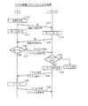
アクセスシステム1の概要動作について、図16に示すフローチャートを用いて説明する。
【0072】
携帯型リーダライタ20は、アクセス要求命令を生成し、1の時間帯において3種類の周波数帯域による搬送波により電波としてアクセス要求命令を出力し(ステップS101)、無線ICタグ10は、いずれか1の搬送波によりアクセス要求命令を受け取り、タグタイプ送信命令を生成して出力し(ステップS102)、携帯型リーダライタ20は、タグタイプ送信命令を受信し、受信したタグタイプに基づいて、周波数帯域とプロトコルとを決定し(ステップS103)、決定した周波数帯域とプロトコルとに基づいて、携帯型リーダライタ20と無線ICタグ10との間で、フリーアクセスプロトコルによる処理(ステップS104)、双方向認証プロトコルにより処理(ステップS105)又は片方向認証プロトコルによる処理(ステップS106)を行い、次に、携帯型リーダライタ20は入出力応答を出力する処理を行う(ステップS107)。
(2)携帯型リーダライタ20のアクセス要求処理の動作
携帯型リーダライタ20のアクセス要求処理の動作について、図17に示すフローチャートを用いて説明する。ここで説明する動作は、図16に示すフローチャートのステップS101に相当する。
【0073】
入力部109は、操作者により操作指示を受け付け、制御部112へ出力し(ステップS111)、制御部112は、前記操作指示からアクセス命令とアクセスアドレスとを生成し(ステップS112)、次に、制御部112は、アクセス要求命令と変復調部識別コード「1」、「2」及び「3」を命令生成部107へ出力する(ステップS113)。命令生成部107は、変復調部識別コード「1」、「2」及び「3」で識別される変復調部104、105及び106へ前記アクセス要求命令を出力する(ステップS114)。
【0074】
変復調部106は、125KHz帯の搬送波により前記アクセス要求命令を出力する(ステップS115)。
また、変復調部105は、13KHz帯の搬送波により前記アクセス要求命令を出力する(ステップS116)。
また、変復調部104は、2.4GHz帯の搬送波により前記アクセス要求命令を出力する(ステップS117)。
【0075】
ここで、ステップS115、S116及びS117は、同一時間帯において、処理が行われる。
(3)無線ICタグ10のタグ読出及び出力処理の動作
無線ICタグ10のタグ読出及び出力処理の動作について、図18に示すフローチャートを用いて説明する。ここで説明する動作は、図16に示すフローチャートのステップS102に相当する。
【0076】
アンテナ部201、復調部202及び命令解読部205を介して、制御部207は、アクセス要求命令を受け取り(ステップS121)、制御部207は、タグタイプ記憶部206から周波数帯域タイプとプロトコルタイプとからなるタグタイプを読み出し(ステップS122)、制御部207は、読み出したタグタイプを含むタグタイプ送信命令を生成し、生成したタグタイプ送信命令を変調部203及びアンテナ部201を介して出力する(ステップS123)。
(4)携帯型リーダライタ20のタグタイプ受信とタグタイプ判断処理
携帯型リーダライタ20のタグタイプ受信とタグタイプ判断処理の動作について、図19に示すフローチャートを用いて説明する。ここで説明する動作は、図16に示すフローチャートのステップS103に相当する。
【0077】
制御部112は、アンテナ部101、変復調部104及び命令解読部108を介して、アンテナ部102、変復調部105及び命令解読部108を介して、又は、アンテナ部103、変復調部106及び命令解読部108を介して、タグタイプ送信命令を受信し(ステップS131)、制御部112は、受信したタグタイプをタグタイプ記憶部117へ書き込む(ステップS132)。制御部112は、次に、タグタイプに含まれるプロトコルタイプが、「フリーアクセス」であるか、「片方向認証」であるか、又は「双方向認証」であるかを判断し、「フリーアクセス」である場合に(ステップS133)、フリーアクセス部113を起動し(ステップS134)、「片方向認証」である場合に(ステップS133)、片方向認証部115を起動し(ステップS135)、「双方向認証」である場合に(ステップS133)、双方向認証部114を起動する(ステップS136)。
(5)アクセスシステム1のフリーアクセスプロトコルによる動作
アクセスシステム1のフリーアクセスプロトコルによる動作について、図20に示すフローチャートを用いて説明する。ここで説明する動作は、図16に示すフローチャートのステップS104に相当する。
【0078】
命令制御部151は、制御部112から入出力命令を受け取り、受け取った入出力命令に基づいてアクセス命令を生成し(ステップS141)、生成したアクセス命令を命令生成部107、変復調部及びアンテナ部を介して出力し、制御部207は、アンテナ部201、復調部202及び命令解読部205を介して、アクセス命令を受け取る(ステップS142)。制御部207は、アクセス命令を入出力部209へ出力し、入出力部209はアクセス命令に従ってアクセスを実行し、アクセス結果を制御部207へ出力し、制御部207は、アクセス応答命令を生成し(ステップS143)、制御部207は、変調部203及びアンテナ部201を介してアクセス応答命令を出力する(ステップS144)。
(6)アクセスシステム1の片方向認証プロトコルによる動作
アクセスシステム1の片方向認証プロトコルによる動作について、図21に示すフローチャートを用いて説明する。ここで説明する動作は、図16に示すフローチャートのステップS106に相当する。
【0079】
乱数生成部241は、乱数として認証子R1を生成し(ステップS151)、暗号化部242は、認証子Raを生成し(ステップS153)、制御部207は、認証子R1を含む認証子送信命令を変調部203及びアンテナ部201を介して出力し、暗号化部161は、命令解読部108から認証子送信命令を受け取り(ステップS152)、暗号化部161は、認証子送信命令に含まれる認証子R1を抽出し、鍵記憶部162から鍵K1を読み出し、鍵K1を用いて、抽出した前記認証子R1に暗号アルゴリズムE1を施して、認証子Rbを生成し(ステップS154)、生成した認証子Rbを命令生成部107、変復調部、アンテナ部を介して出力し、比較部244は、命令解読部205から認証子応答命令を受け取り(ステップS155)、受け取った認証子応答命令から認証子Rbを抽出し、暗号化部242から認証子Raを受け取り、抽出した認証子Rbと受け取った認証子Raとが一致しているか否かを判定し、一致していない場合には(ステップS156)、制御部207は、アクセス不許可を含むアクセス応答命令を変調部203及びアンテナ部201を介して出力し、制御部112は、アンテナ部、変復調部及び命令解読部108を介して、アクセス応答命令を受け取り(ステップS156)、アクセス不許可ならば(ステップS158)、制御部112は、アクセスを中止する。アクセス許可ならば(ステップS158)、ステップS159からS162において、図20のフローチャートにおけるステップS141からステップS144と同様である。
(7)アクセスシステム1の双方向認証プロトコルによる動作
アクセスシステム1の双方向認証プロトコルによる動作について、図22に示すフローチャートを用いて説明する。ここで説明する動作は、図16に示すフローチャートのステップS105に相当する。
【0080】
ステップS171からS178までは、図21に示すステップS151からS158までと同じである。
ステップS179からS184までは、ステップS171からS178までと同様である。ステップS184において、認証子Rcと認証子Rdが不一致なら、携帯型リーダライタ20は、アクセスを中止する。
【0081】
ステップS185からS188までは、図20のフローチャートのステップS141からS144までと同様である。
(8)携帯型リーダライタ20の入出力応答処理の動作
携帯型リーダライタ20の入出力応答処理の動作について、図23に示すフローチャートを用いて説明する。ここで説明する動作は、図16に示すフローチャートのステップS107に相当する。
【0082】
制御部112は、フリーアクセス部113、双方向認証部114又は片方向認証部115からアクセス応答命令を受け取り、アクセス応答命令から終了コードを抽出し、終了コードが10(アクセス不許可)、11(指定アドレス無し)、12(書込不許可)及び13(書込領域不足)であるなら(ステップS191)、それぞれの終了コードに応じて、制御部112は、メッセージ「アクセス不許可」、「指定アドレス無し」、「書込不許可」及び「書込領域不足」を表示部110へ出力し、表示部110は、受け取ったメッセージをメッセージ表示部134へ表示する(ステップS192)。
【0083】
また、終了コードが0(正常終了)である場合(ステップS191)、アクセス応答命令に対応するアクセス命令がRead命令であるとき(ステップS193)、制御部112は、それぞれ、メッセージ「読出終了」を表示部110へ出力し、表示部110は、受け取ったメッセージをメッセージ表示部134へ表示し、制御部112は、アクセス応答命令から読出内容を抽出し、抽出した読出内容を表示部110へ出力し(ステップS197)、表示部110は、受け取った読出内容をデータ表示部133へ表示する(ステップS198)。
【0084】
アクセス応答命令に対応するアクセス命令がWrite命令であるとき(ステップS193)、制御部112は、それぞれ、メッセージ「書込終了」を表示部110へ出力し(ステップS194)、表示部110は、受け取ったメッセージをメッセージ表示部134へ表示する(ステップS195)。
1.7 まとめ
上記に説明したように、携帯型リーダライタ20は、同一時間帯において、3種類の搬送波によりアクセス要求命令を送信し、無線ICタグ10は、自身の周波数帯域タイプと通信プロトコルタイプとを送信し、さらに、携帯型リーダライタ20は、受信した周波数帯域タイプと通信プロトコルタイプとを用いて、無線ICタグ10へ情報を書込み、又は無線ICタグ10から情報を読み出す。
【0085】
こうして、無線ICタグ10の受信できる周波数帯域が異なる場合であっても、携帯型リーダライタ20は、無線ICタグ10との間で通信を行える。
部品や部材などの「物」に添付され若しくは埋め込まれる無線ICタグ、又は人の入退出用若しくは乗車券用として用いられる無線ICカードなどの応用例により、規格が不統一であり、種々の仕様(通信周波数、変復調方式、プロトコル、データ形式、セキュリティ方式又は暗号化方式など)が混在して使用されている場合であっても、上記に説明したように、リーダライタと無線ICタグとの間で通信が行える。
【0086】
なお、上記の実施の形態において、タグタイプは、さらに、変復調方式、データ形式、セキュリティ方式又は暗号化方式を含むとしてもよい。
1.8 携帯型リーダライタ20の変形例(1)
携帯型リーダライタ20は、次のようにしてもよい。
携帯型リーダライタ20は、図24のフローチャートに示すように、125KHz帯によりアクセス要求命令の生成処理を行い(ステップS201)、125KHz帯によりアクセス要求命令を出力する(ステップS202)。
【0087】
携帯型リーダライタ20は、125KHz帯によりタグタイプの受信を待ち受け(ステップS203)、タグタイプの受信があれば(ステップS204)、125KHz帯により無線ICタグ10との間でアクセス処理を行う(ステップS205)。
所定時間内にタグタイプの受信が無ければ(ステップS204)、次に、携帯型リーダライタ20は、13MHz帯によりアクセス要求命令の生成処理を行い(ステップS206)、13MHz帯によりアクセス要求命令を出力する(ステップS207)。
【0088】
携帯型リーダライタ20は、13MHz帯によりタグタイプの受信を待ち受け(ステップS208)、タグタイプの受信があれば(ステップS209)、13MHz帯により無線ICタグ10との間でアクセス処理を行う(ステップS210)。
所定時間内にタグタイプの受信が無ければ(ステップS209)、次に、携帯型リーダライタ20は、2.4GHz帯によりアクセス要求命令の生成処理を行い(ステップS211)、2.4GHz帯によりアクセス要求命令を出力する(ステップS212)。無線ICタグ10は、タグタイプを読み出し(ステップS213)、出力する(ステップS214)。
【0089】
携帯型リーダライタ20は、2.4GHz帯によりタグタイプの受信を待ち受け(ステップS215)、タグタイプの受信があれば(ステップS216)、2.4GHz帯により無線ICタグ10との間でアクセス処理を行う(ステップS217)。
これにより、無線ICタグ10の受信できる周波数帯域が異なる様々な仕様であっても、携帯型リーダライタ20は、無線ICタグ10との間で通信を行える。
1.9 携帯型リーダライタ20の変形例(2)
携帯型リーダライタ20は、次のようにしてもよい。
【0090】
携帯型リーダライタ20は、図25に一例として示すように、周波数帯域タイプ履歴テーブル251を有している。
周波数帯域タイプ履歴テーブル251は、直近の過去にアクセスした無線ICタグの周波数帯域タイプを10個分記憶している。
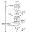
携帯型リーダライタ20は、図26のフローチャートに示すように、周波数帯域タイプ履歴テーブル251から周波数帯域タイプを全て読み出し、周波数帯域タイプ履歴テーブル251に含まれる周波数帯域タイプの種類毎に、その発生頻度を計数し(ステップS221)、最も頻度の高い周波数帯域を第1出力周波数帯域とし(ステップS222)、次に頻度の高い周波数帯域を第2出力周波数帯域とし(ステップS223)、最も頻度の低い周波数帯域を第3出力周波数帯域とする(ステップS224)。このようにして、周波数帯域による出力順序を第1出力周波数帯域、第2出力周波数帯域、第3出力周波数帯域の順に決定する。
【0091】
次に、上記の変形例(1)において、この順序により、アクセス要求命令を出力する。具体的には、図24に示すフローチャートのステップS201〜S202において、第1出力周波数帯域を用い、ステップS206〜S207において、第2出力周波数帯域を用い、ステップS211〜S213において、第3出力周波数帯域を用いる。
【0092】
こうして無線ICタグとの通信が終了すると、携帯型リーダライタ20は、無線ICタグとの通信に用いた周波数帯域タイプを新たに周波数帯域タイプ履歴テーブル251に書き込み、最も最初に書き込まれた周波数帯域タイプを周波数帯域タイプ履歴テーブル251から削除する。
このように、過去に通信に用いた周波数帯域タイプの頻度を用いて、次に用いる周波数帯域タイプの優先順位を決定し、決定した優先順位に従った周波数帯域の順序により、アクセス要求命令を送信する。これにより、無線ICタグ10の受信できる周波数帯域が異なる様々な仕様であっても、携帯型リーダライタ20は、無線ICタグ10との間で通信を行え、また、無線ICタグ10との間で用いることのできる周波数帯域を統計的に素早く決定できる。
1.10 アクセスシステムの変形例
無線ICタグ10と携帯型リーダライタ20とは、両者の間の通信のセキュリティを確保するために、通信されるデータを暗号化するとしていもよい。無線ICタグ10と携帯型リーダライタ20とは、暗号化及び対応する復号化のためのプログラムを記憶しており、一方の装置は、データを暗号化して送信し、他方の装置は、暗号化されたデータを受信して復号する。暗号アルゴリズムの一例は、カオス暗号であり、ロジスティックマップ
X(t+1)=4X(t){1−X(t)}
を逐次計算させることにより、カオスブロック暗号を生成する。
1.11 アクセスシステムの変形例
アクセスシステムは、次のように構成してもよい。
【0093】
メモリ部210は、複数回の情報の読出しと複数回の情報の上書きが可能な半導体メモリから構成される第1領域と、複数回の情報の読出しと一度だけの情報の書込みが可能な半導体メモリから構成される第2領域とを含む。図12において、非プロテクト部231及びプロテクト部232は、第1領域であり、ワンタイム233は、第2領域である。
【0094】
無線ICタグは、受信したアクセス命令に基づいて、前記第1領域又は前記第2領域のいずれにアクセスするか判断する。ここで、前記判断は、アクセス命令に含まれる物理アドレスを用いて行う。つまり、物理アドレスが第1領域又は第2領域のいずれを指し示しているかにより判断する。次に、前記判断結果に基づいて、前記第1領域又は前記第2領域にアクセスする。
【0095】
第2領域に記憶されている情報の一例は、物品の保証期間、保証番号である。アクセス装置の一例は、前記情報記憶媒体が添付された物品の販売を管理する販売管理装置である。アクセス装置は、操作者から入金操作を受け付け、前記入金操作が受け付けられた場合に、前記物品の保証条件を示す保証情報の前記第2領域への書き込みを示すアクセス指示を要求するアクセス要求を生成する。情報記憶媒体は、前記第2領域へのアクセスであると判断し、前記判断結果に基づいて、前記保証情報を前記第2領域へ書き込む。
【0096】
販売時点での応用例として、販売店にて、その販売日、販売店名及びその製品の保証期間や保証条件などの保証情報をリーダライタを介して、無線ICタグに記憶させおくことにより、使用時の不具合対応、アップグレード対応、品質問題での回収対応など幅広いサービス・メンテナンス対応が可能となる。こうして、従来の保証書の保管や紛らわしい問い合わせ処理が不要となり、顧客満足度の向上に役立てることができる。
【0097】
第2領域に記憶されている情報の別の一例は、物品の回収時のマニフェスト情報である。アクセス装置の一例は、前記情報記憶媒体が添付された物品の回収を管理する回収管理装置である。アクセス装置は、操作者から操作を受け付け、前記操作が受け付けられた場合に、前記物品のマニフェスト情報の前記第2領域への書き込みを示すアクセス指示を要求するアクセス要求を生成する。情報記憶媒体は、前記第2領域へのアクセスであると判断し、前記判断結果に基づいて、前記マニフェスト情報を前記第2領域へ書き込む。
【0098】
現在施行が考えられているマニフェスト方式は、数枚綴りの紙の伝票を用いる。対象として家電製品(テレビ受像機、エアコン、冷蔵庫、洗濯機)であり、これらを排出者が販売店に持参し、その処理代金を支払い、その処理登録伝票として、マニフェスト伝票を受け取る。処理のスクラップに係る業者は、これを5年間保存する仕組みである。排出者からの処理に関する問い合わせに対し、処理が適正にされたことをこの伝票にて明確化する。しかしこの仕組みは、大量の紙と、その保管費用、検索チェックの費用がかかることが予想される。これを解決するために、回収・リサイクルの過程で、機器に埋め込まれた無線ICタグに記録されている情報をリーダライタにより読み取り、ホストコンピュータに記憶し、必要に応じて、インターネットなどの通信手段を介して排出者がチェックできる。こうして、むだなく、速く低コストの回収システムが構築できる。
【0099】
さらに、あらかじめ無線ICタグに記憶させておいた環境負荷物質の種類や量を用いて、回収リサイクル時に、その内容を読み取り、回収記録として利用できる。また、リサイクル率の算出に当たり、このタグ内に製造時に記録された部材毎のデータ(種類、重量)をリーダライタにより読み取り、分別、リサイクル量の記録として、ホストコンピュータに書込み、利用することができる。
【0100】
また、製品の分解情報や環境負荷物質の取り出し方法など、より込み入った手順や取り扱い方法に関しては、この無線ICタグ内に全てを記憶させることは、メモリ容量、価格等から無理があるので、これらの方法の検索用の識別コードのみを記憶しておき、これらの方法については、ホストコンピュータにその詳細を記憶させておく。リーダライタにより識別コードを無線ICタグから読み出し、その識別コードを用いて、該当する方法をホストコンピュータから読み出す。読み出した方法をリーダライタやパソコンに表示、印刷するようにしてもよい。
【0101】
第2領域に記憶されている情報の別の一例は、物品を構成する環境負荷物質に関する環境負荷物質情報(例えば、代替フロンガスの種類や量)である。アクセス装置の一例は、前記情報記憶媒体が添付された物品の製造を管理する製造管理装置である。アクセス装置は、操作者から操作を受け付け、前記操作が受け付けられた場合に、前記物品に含まれる環境負荷物質を示す環境負荷物質情報の前記第2領域への書き込みを示すアクセス指示を要求するアクセス要求を生成する。記憶情報媒体は、前記第2領域へのアクセスであると判断し、前記判断結果に基づいて、前記環境負荷物質情報を前記第2領域へ書き込む。前記環境負荷物質情報以外の他の例は、組み立て条件、加工条件、検査条件及びその測定値などの生産時の製造条件情報、ロット番号、生産工場の名称、製造日である。リサイクル回収時、製品の修理等のサービス対応時に、上記情報を読取、サービス、回収リサイクル等に役立てることができる。製品の修理、回収時に、前記製造条件を読み出し、読み出した製造条件を用いて、製品の修理、解体、再利用を行うとしてもよい。
2 第2の実施の形態
本発明の別の1の実施の形態としての印刷システム及び通信システムについて説明する。
2.1 印刷システム及び通信システムの構成
印刷シテスムは、図27に外観を示すように、記憶領域を有する無線ICタグ10が添付された物品と、印刷装置60とから構成されている。無線ICタグ10は、125KHz帯の周波数帯域において通信を行う。印刷装置60は、印字ヘッド61とアンテナ62を備え、無線ICタグ10に記録されている情報を読み出し、読み出した情報に基づいてバーコードを形成し、形成したバーコードを前記物品の包装材の表面上に印刷する。バーコード63が前記包装材上の印刷されている。印刷装置60は、管理装置50に接続されており、前記読み出した情報を管理装置50へ出力し、管理装置50は前記情報を受け取り、記憶し、利用する。
【0102】
また、通信システムは、図28及び図30に示すように、記憶領域を有する無線ICタグ10が添付された物品と、携帯電話型リーダライタ70と、無線基地局85と、無線基地局85が接続されている公衆通信網86と、公衆通信網86を介して無線基地局85と接続されている管理センタ装置80と、管理センタ装置80と接続されている公衆通信網87と、生産センタ装置91と、物流センタ装置92と、販売センタ装置93と、サービスセンタ装置94と、回収リサイクルセンタ装置95とから構成されており、前記物品は、外表面にバーコード63が印刷された包装材により包装され、生産センタ装置91、物流センタ装置92、販売センタ装置93、サービスセンタ装置94及び回収リサイクルセンタ装置95は、それぞれ公衆通信網87を介して管理センタ装置80と接続されている。携帯電話型リーダライタ70は、光を用いてバーコード63からバーコード情報を読み出し、無線ICタグ10から電波を用いてタグ情報を読み出し、読み出したバーコード情報と読み出したタグ情報の一部とが一致している場合に、タグ情報が正しく読み出されたと判断する。さらに、携帯電話型リーダライタ70は、無線基地局85、公衆通信網86、管理センタ装置80及び公衆通信網87を介して、生産センタ装置91、物流センタ装置92、販売センタ装置93、サービスセンタ装置94及び回収リサイクルセンタ装置95のいずれかに読み出したタグ情報を送信し、生産センタ装置91、物流センタ装置92、販売センタ装置93、サービスセンタ装置94及び回収リサイクルセンタ装置95のいずれかは、前記タグ情報を記憶する。このように、無線ICタグ10と生産センタ装置91、物流センタ装置92、販売センタ装置93、サービスセンタ装置94及び回収リサイクルセンタ装置95のいずれかは、通信を行う。
2.2 印刷装置60の構成
印刷装置60は、図29に示すように、アンテナ部301、変復調部302、命令生成部303、命令解読部304、入力部305、表示部306、制御部307、印刷部308及び記憶部309から構成されている。
【0103】
アンテナ部301、変復調部302、命令生成部303、命令解読部304及び制御部307は、図2に示す携帯型リーダライタ20の構成要素であるアンテナ部、変復調部、命令生成部、命令解読部及び制御部と同様の機能、作用、構成を有するので説明を省略し、携帯型リーダライタ20との相違点を中心にして説明する。
【0104】
制御部307は、アンテナ部301、変復調部302及び命令解読部304を介して、タグタイプ送信命令を受け取り、タグタイプ送信命令からタグタイプを抽出し、抽出したタグタイプを印刷部308へ出力する。
印刷部308は、制御部307からタグタイプを受け取り、受け取ったタグタイプを元にして、バーコードを形成し、形成したバーコードを物品の包装材の外表面上に印刷する。
【0105】
入力部305は、操作者による各種の操作指示を受け付ける。
表示部306は、制御部307から印刷に関する状態情報を受け取り、表示する。
記憶部309は、各種情報を記憶する。
なお、制御部307は、タグタイプに含まれる周波数帯域タイプのみを印刷部308へ出力し、印刷部308は、受け取った周波数帯域タイプを元にしてバーコードを形成するとしてもよい。また、周波数帯域タイプに代えて、プロトコルタイプを用いてもよい。
【0106】
印刷部308は、2次元コード又は文字を形成し、これらを印刷するとしてもよい。
2.3 携帯電話型リーダライタ70の構成
携帯電話型リーダライタ70は、図31に示すように、アンテナ部321、変復調部322、命令生成部323、命令解読部324、入力部331、表示部332、制御部333、記憶部334、発光部325、発光制御部326、受光部328、コード解読部329、通信制御部335、無線部336、アンテナ部337、スピーカ338及びマイク339から構成されている。
【0107】
アンテナ部321、変復調部322、命令生成部323、命令解読部324及び制御部333は、図2に示す携帯型リーダライタ20の構成要素であるアンテナ部、変復調部、命令生成部、命令解読部及び制御部と同様の機能、作用、構成を有するので説明を省略し、携帯型リーダライタ20との相違点を中心にして説明する。
【0108】
発光制御部326は、制御部333から発光指示を受け取る。発光指示を受け取ると、発光部325に対して発光するように制御する。
発光部325は、発光制御部326の制御によりレーザ光を発光し走査する。発光部325により発生した光は、物品の包装材の外表面に印刷されたバーコードに照射され、バーコードにおいて反射する。前記印刷されたバーコードは、物品に添付されている無線ICタグ10のタグタイプを表示しているものである。
【0109】
受光部328は、バーコードにおいて反射した光を受け取り、電気信号に変換してコード解読部329へ出力する。
コード解読部329は、受光部328から電気信号を受け取り、受け取った電気信号を解読して、バーコード情報を生成し、生成したバーコード情報を制御部333へ出力する。
【0110】
制御部333は、コード解読部329からバーコード情報を受け取り、バーコード情報に含まれるタグタイプを抽出する。次に、バーコード情報から抽出したタグタイプと、電波により受信したタグタイプとを比較して、一致しているか否かを判断し、一致していないなら、表示部332に対して、不一致の旨を示すエラーメッセージを出力し、表示部332は、前記エラーメッセージを表示する。また、不一致の旨を示すエラー音声情報を通信制御部335を介して、スピーカ338へ出力し、スピーカ338は、エラー音声を出力する。
【0111】
一致しているなら、制御部333は、無線ICタグ10から配送番号と配送実績日と管理センタ電話番号とを読み出し、読み出した配送番号と配送実績日と管理センタ電話番号とを通信制御部335へ出力する。ここで、管理センタ電話番号は、管理センタ装置80の電話番号である。
通信制御部335は、CPU、音声CODEC、信号処理LSI、ベースバンドフィルタなどからなり、制御部333から配送番号と配送実績日と管理センタ電話番号とを受け取る。通信制御部335は、前記管理センタ電話番号により発呼するように、無線部336を制御し、無線部336は、アンテナ部337、無線基地局85及び公衆通信網86を介して、管理センタ装置80と通信回線を接続する。ここで、無線部336は、変復調器、シンセサイザ、AGC(可変利得)アンプ、周波数変換器、高周波増幅器、アンテナ共用器などからなる。次に、通信制御部335は、前記接続された通信回線を介して、配送番号と配送実績日とを管理センタ装置80へ送信する。次に、通信制御部335は、無線部336に対して接続された通信回線を切断するように制御し、無線部336は、通信回線を切断する。
2.4 管理センタ装置80の構成
管理センタ装置80は、図32に示すように、データ記憶部351と入出力制御部352と回線接続部353と電話番号記憶部354とから構成され、以下に示す生産センタ装置91、物流センタ装置92、販売センタ装置93、サービスセンタ装置94及び回収リサイクルセンタ装置95と、携帯電話型リーダライタ70との間を中継する中継装置(中継管理装置)である。
【0112】
回線接続部353は、公衆通信網86、87を介して、他の装置との通信回線を接続する。
入出力制御部352は、回線接続部353、公衆通信網86及び無線基地局85を介して、携帯電話型リーダライタ70と接続され、携帯電話型リーダライタ70から配送番号と配送実績日とを受信し、受信した配送番号と配送実績日とをデータ記憶部351に書き込む。その後、入出力制御部352は、回線接続部353に対して接続された通信回線を切断するように制御し、回線接続部353は、通信回線を切断する。
【0113】
次に、入出力制御部352は、データ記憶部351に記憶されている配送番号と配送実績日とを読み出し、読み出した情報が、生産センタ、物流センタ、販売センタ、サービスセンタ及び回収リサイクルセンタのいずれのセンタと関連しているかを判断する。関連するセンタの電話番号を電話番号記憶部354から読み出し、読み出した電話番号により、発呼するように、回線接続部353を制御し、回線接続部353は、公衆通信網87を介して、生産センタ装置91、物流センタ装置92、販売センタ装置93、サービスセンタ装置94及び回収リサイクルセンタ装置95のいずれかであって、前記電話番号により特定されるセンタ装置と通信回線を接続し、次に、入出力制御部352は、読み出した配送番号と配送実績日とを、回線接続部353、公衆通信網87を介して、前記電話番号により特定されるセンタ装置へ送信する。その後、入出力制御部352は、回線接続部353に対して接続された通信回線を切断するように制御し、回線接続部353は、通信回線を切断する。
【0114】
電話番号記憶部354は、センタ名称と対応する電話番号との組を複数個記憶している。
生産センタ装置91、物流センタ装置92、販売センタ装置93、サービスセンタ装置94及び回収リサイクルセンタ装置95と、携帯電話型リーダライタ70との間に管理センタ装置80を設置する理由は以下の通りである。
【0115】
数多くの無線ICタグは、物品に添付され、物品の寿命が尽きるまで、10年間や20年間などの長期間に渡って利用される。無線ICタグの内部に生産センタ装置91などの電話番号を記録している仮定し、この電話番号を変更しようとすると、数多くの無線ICタグに記憶されている電話番号を変更しなければならない。生産センタ装置91は、この電話番号を前記期間に渡って維持しなければならない。同一の電話番号を長期間に渡って維持することの困難性を回避するために、また数多くの無線ICタグの書き換えを回避するために、無線ICタグ10内部に記録されている電話番号の数をできる限り少なくし、管理センタ装置80の電話番号のみを記録することとしている。管理センタ装置80は、生産センタ装置91、物流センタ装置92、販売センタ装置93、サービスセンタ装置94及び回収リサイクルセンタ装置95の電話番号を記憶しており、これらの装置への中継装置となりうる。また、管理センタ装置80に記録されている電話番号の変更は容易である。
2.5 生産センタ装置91、物流センタ装置92、販売センタ装置93、サービスセンタ装置94及び回収リサイクルセンタ装置95の構成
物流センタ装置92は、データ記憶部と入出力制御部と回線接続部とから構成される。
【0116】
回線接続部は、公衆通信網87を介して、他の装置との通信回線を接続する。
入出力制御部は、回線接続部が公衆通信網87を介して、管理センタ装置80と接続されたときに、管理センタ装置80から情報を受け取る。前記情報の具体的な一例は、配送番号と配送実績日とである。入出力制御部は、受け取った情報をデータ記憶部に書き込む。
【0117】
生産センタ装置91、販売センタ装置93、サービスセンタ装置94及び回収リサイクルセンタ装置95についても、同様の構成である。
2.6 印刷システム及び通信システムの動作
印刷システム及び通信システムの動作について説明する。
(1)印刷システムの動作
印刷システムの動作について、図33に示すフローチャートを用いて説明する。
【0118】
印刷装置60は、アクセス要求命令を生成し、電波により生成したアクセス要求命令を送信する(ステップS301)。無線ICタグ10は、アクセス要求命令を受信し、タグタイプを読み出し、読み出したタグタイプを含むタグタイプ送信命令を電波により送信する(ステップS302)。印刷装置60の制御部307は、アンテナ部301、変復調部302及び命令解読部304を介して、タグタイプ送信命令を受け取り、タグタイプ送信命令からタグタイプを抽出し、抽出したタグタイプを印刷部308へ出力する(ステップS303)。印刷部308は、制御部307からタグタイプを受け取り、受け取ったタグタイプを元にして、バーコードを形成し(ステップS304)、形成したバーコードを物品の包装材の外表面上に印刷する(ステップS305)。
(2)携帯電話型リーダライタ70の動作
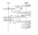
携帯電話型リーダライタ70の動作について、図34及び図35に示すフローチャートを用いて説明する。
【0119】
携帯電話型リーダライタ70は、操作者により無線ICタグ10から情報を読み出し、物流センタへ送信する旨の操作を受け付け(ステップS311)、アクセス要求命令を生成し、電波により生成したアクセス要求命令を送信する(ステップS312)。無線ICタグ10は、アクセス要求命令を受信し、タグタイプを読み出し、読み出したタグタイプを含むタグタイプ送信命令を電波により送信する(ステップS313)。携帯電話型リーダライタ70の制御部333は、アンテナ部321、変復調部322及び命令解読部324を介して、タグタイプ送信命令を受け取り、タグタイプ送信命令からタグタイプを抽出する(ステップS314)。これ以降、携帯電話型リーダライタ70は抽出したタグタイプにより、無線ICタグ10との通信を行う。次に、制御部333は、発光制御部326に対して発光指示を出力し、発光制御部326は、制御部333から発光指示を受け取り、発光部325は、発光制御部326の制御により発光する(ステップS315)。発光部325により発生した光は、物品の包装材の外表面に印刷されたバーコードに照射され、バーコードにおいて反射する。受光部328は、前記反射光を受け取り、電気信号に変換してコード解読部329へ出力し、コード解読部329は、受光部328から電気信号を受け取り、受け取った電気信号を解読して、バーコード情報を生成し、生成したバーコード情報を制御部333へ出力する(ステップS316)。制御部333は、コード解読部329からバーコード情報を受け取り、バーコード情報に含まれるタグタイプを抽出する(ステップS317)。次に、バーコード情報から抽出したタグタイプと、電波により受信したタグタイプとを比較して、一致しているか否かを判断し、一致していないなら(ステップS318)、表示部332に対して、不一致の旨を示すエラーメッセージを出力し、表示部332は、前記エラーメッセージを表示し、また、制御部333は、不一致の旨を示すエラー音声情報を通信制御部335を介して、スピーカ338へ出力し、スピーカ338は、エラー音声を出力する(ステップS319)。
【0120】
一致しているなら(ステップS318)、制御部333は、配送番号と配送実績日と管理センタ電話番号とを無線ICタグ10から読み出すためのアクセス命令を生成し(ステップS320)、生成したアクセス命令を電波により送信し(ステップS321)、無線ICタグ10は、アクセス命令を受信し、内部に記憶している配送番号と配送実績日と管理センタ電話番号とを読み出し(ステップS322)、読み出した配送番号と配送実績日と管理センタ電話番号とをアクセス応答命令により送信し(ステップS323)、制御部333は、アクセス応答命令を受信し、アクセス応答命令から配送番号と配送実績日と管理センタ電話番号とを抽出し、通信制御部335は、制御部333から配送番号と配送実績日と管理センタ電話番号とを受け取る(ステップS324)。通信制御部335は、前記管理センタ電話番号により発呼するように、無線部336を制御し、無線部336は、アンテナ部337、無線基地局85及び公衆通信網86を介して、管理センタ装置80と通信回線を接続する(ステップS325)。次に、通信制御部335は、前記接続された通信回線を介して、配送番号と配送実績日とを管理センタ装置80へ送信する(ステップS326)。次に、通信制御部335は、無線部336に対して接続された通信回線を切断するように制御し、無線部336は、通信回線を切断する(ステップS327)。
(3)管理センタ装置80の動作
管理センタ装置80の動作について、図36に示すフローチャートを用いて説明する。
【0121】
入出力制御部352は、回線接続部353、公衆通信網86及び無線基地局85を介して、携帯電話型リーダライタ70と接続され、携帯電話型リーダライタ70から配送番号と配送実績日とを受信し、受信した配送番号と配送実績日とをデータ記憶部351に書き込み、入出力制御部352は、回線接続部353に対して接続された通信回線を切断するように制御し、回線接続部353は、通信回線を切断する(ステップS351)。
【0122】
次に、入出力制御部352は、データ記憶部351に記憶されている配送番号と配送実績日とを読み出し、読み出した情報が、生産センタ、物流センタ、販売センタ、サービスセンタ及び回収リサイクルセンタのいずれのセンタと関連しているかを判断する(ステップS352)。関連するセンタの電話番号を電話番号記憶部354から読み出し(ステップS353、ステップS354、ステップS355)、読み出した電話番号により、発呼するように、回線接続部353を制御し、回線接続部353は、公衆通信網87を介して、生産センタ装置91、物流センタ装置92、販売センタ装置93、サービスセンタ装置94及び回収リサイクルセンタ装置95のいずれかであって、前記電話番号により特定されるセンタ装置と通信回線を接続し(ステップS356)、次に、入出力制御部352は、読み出した配送番号と配送実績日とを、回線接続部353、公衆通信網87を介して、前記電話番号により特定されるセンタ装置へ送信する(ステップS357)。その後、入出力制御部352は、回線接続部353に対して接続された通信回線を切断するように制御し、回線接続部353は、通信回線を切断する(ステップS358)。
(4)生産センタ装置91、物流センタ装置92、販売センタ装置93、サービスセンタ装置94及び回収リサイクルセンタ装置95の動作
物流センタ装置92の動作について、図37に示すフローチャートを用いて説明する。
【0123】
物流センタ装置92の入出力制御部は、回線接続部が公衆通信網87を介して、管理センタ装置80と接続されたときに、管理センタ装置80から配送番号と配送実績日とを受信し(ステップS360)、入出力制御部は、受信し配送番号と配送実績日とをデータ記憶部に書き込む(ステップS361)。
なお、生産センタ装置91、販売センタ装置93、サービスセンタ装置94及び回収リサイクルセンタ装置95の動作についても同様である。
2.7 印刷システムの変形例(1)
印刷装置60は、無線ICタグ10の添付されている物品を包装する包装材にバーコードを印刷するとしているが、次のようにしてもよい。
【0124】
テープの上に複数の無線ICタグ10が一定の間隔を於いて付着されており、また、各無線ICタグ10が付着している位置に対応して前記テープの上に識別用のマークが印刷されている。前記テープは、リールに巻き取られている。
印刷装置60は、リールに巻き取られているテープを引き出しながら、識別用のマークを光により検出する。マークを検出すると、上記に説明したように、印刷装置60は、検出したマークに近接してテープ上に付着している無線ICタグ10からタグタイプを読み出し、読み出したタグタイプによりバーコードを形成し、形成したバーコードを前記無線ICタグ10の上面に印刷する。印刷が終了すると、さらにテープを引き出し、次の無線ICタグの上面に同様にしてバーコードを印刷する。印刷装置60は、引き出したテープを、別のリールに徐々に巻き取っていく。
【0125】
バーコードの印刷された無線ICタグが付着されたテープを巻き取った前記別のリール400の外観を図38(a)に示す。この図に示すように、テープ402上に、無線ICタグ403が付着され、無線ICタグ403の上面にバーコードが印刷されている。無線ICタグ403の近辺でテープ402上に、識別用のマーク404が印刷されている。
【0126】
バーコードの印刷された無線ICタグが付着されたテープを巻き取ったリールは、電子回路基盤に電子部品を装着する際に、電子部品を供給するために用いられる。
このように、バーコードを無線ICタグの外表面に印刷するとしてもよい。
2.8 印刷システムの変形例(2)
印刷装置60は、無線ICタグの添付されている物品を包装する包装材にバーコードを印刷するとしているが、無線ICタグの添付されている物品の面上にバーコードを印刷するとしてもよい。
【0127】
無線ICタグの添付されている物品の一例を図38(b)に示す。この図に示すように、物品410の前面下部において、無線ICタグ411が添付され、無線ICタグ411にロゴ412が添付されている。物品410の側面下部において、バーコード413が印刷されている。
2.9 印刷システムの変形例(3)
印刷装置60は、無線ICタグ10の添付されている物品を包装する包装材にタグタイプを表示するバーコードを印刷するとしているが、次のようにしてもよい。
【0128】
変形例としての印刷システムの動作について、図39に示すフローチャートを用いて説明する。
変形例としての印刷装置60は、アクセス要求命令を生成し、電波により生成したアクセス要求命令を送信する(ステップS381)。無線ICタグ10は、アクセス要求命令を受信し、タグタイプを読み出し、読み出したタグタイプを含むタグタイプ送信命令を電波により送信する(ステップS382)。印刷装置60は、タグタイプ送信命令を受け取る(ステップS382)。
【0129】
次に、変形例としての印刷装置60は、無線ICタグを個別に識別する識別ココードを無線ICタグから読み出す旨の識別コードのアクセス命令を生成し、電波により生成したアクセス命令を送信する(ステップS384)。無線ICタグ10は、前記アクセス命令を受信し、識別コードを識別コード記憶部208から読み出し(ステップS385)、読み出した識別コードを含むアクセス応答命令を生成し、生成したアクセス応答命令を電波により送信する(ステップS386)。印刷装置60は、アクセス応答命令を受け取る(ステップS387)。印刷装置60は、アクセス応答命令から識別コードを抽出し、抽出した識別コードを印刷部308へ出力する(ステップS388)。印刷部308は、制御部307から識別コードを受け取り、受け取った識別コードを元にして、バーコードを形成し(ステップS388)、形成したバーコードを物品の包装材の外表面上に印刷する(ステップS389)。
2.9 印刷システムの変形例(4)
印刷装置60は、次のようにしてバーコードを印刷してもよい。
【0130】
印刷装置60は、無線ICタグ10が記憶しているタグタイプを読み出して、読み出したタグタイプに暗号アルゴリズムを施して暗号化タグタイプを生成し、生成した暗号化タグタイプからバーコードを形成し、形成したバーコードを印刷する。
また、印刷装置60は、無線ICタグ10が記憶しているタグタイプを読み出して、乱数を生成する。次に、生成した乱数と読み出したタグタイプとを1ビット毎に交互に併合する。併合された結果に対して暗号アルゴリズムを施して暗号化タグタイプを生成し、生成した暗号化タグタイプからバーコードを形成し、形成したバーコードを印刷する。
【0131】
また、印刷装置60は、無線ICタグ10が記憶しているタグタイプを読み出して、乱数を生成する。次に、生成した乱数と読み出したタグタイプとを1ビット毎に交互に併合する。併合された結果からバーコードを形成し、形成したバーコードを印刷する。
携帯電話型リーダライタ70は、上記により印刷されたバーコードから元のタグタイプを復元する場合には、それぞれ、逆の手順を施す。
【0132】
前記印刷媒体の面上にタグタイプに暗号アルゴリズムを施して生成された暗号化タグタイプを表示するバーコード(形象)が印刷されている。携帯電話型リーダライタ70は、光を用いて前記印刷媒体面上に印刷されているバーコードを読み出し、読み出したバーコードに基づいて暗号化タグタイプを生成し、生成した暗号化タグタイプに復号アルゴリズムを施してタグタイプを生成する。ここで、前記復号アルゴリズムは、平文に前記暗号アルゴリズムを施して生成された暗号文を復号するアルゴリズムである
また、前記印刷媒体の面上にタグタイプと他の情報とを所定の基準により併合して生成された併合情報を表示するバーコードが印刷されている。携帯電話型リーダライタ70は、光を用いて前記印刷媒体面上に印刷されているバーコードを読み出し、読み出したバーコードに基づいて併合情報を生成し、生成した併合情報から前記所定の基準により部分の情報を抽出してタグタイプを生成する。ここで、前記所定の基準は、2個の情報を1ビット毎に交互に取り出して結合することである。他の情報の一例は、ランダムに生成された乱数である。
【0133】
また、前記印刷媒体の面上にタグタイプと他の情報とを所定の基準により併合して生成された併合情報にさらに暗号アルゴリズムを施して暗号化情報を生成し、生成した暗号化情報を表示するバーコードが印刷されている。携帯電話型リーダライタ70は、光を用いて前記印刷媒体面上に印刷されているバーコードを読み出し、読み出したバーコードに基づいて形象情報を生成し、生成した形象情報に復号アルゴリズムを施して暗号化前の併合情報を生成し、生成した併合情報から前記所定の基準により部分の情報を抽出してタグタイプとする。
【0134】
また、上記において、バーコードを用いてるとしているが、2次元コードを用いてもよい。2次元コードの生成及び2次元コードからの情報の復元については、公知であるので説明を省略する。また、文字を用いてもよい。文字からの情報の復元については、公知である。
また、上記において、タグタイプの代わりに、無線ICタグ10を個別に識別する媒体識別コードを用いてもよい。また、タグタイプに含まれる周波数帯域タイのみプを用いてもよいし、プロトコルタイプのみを用いてもよい。
【0135】
また、変復調方式、データ形式、セキュリティ方式又は暗号化方式をそれぞれ識別する情報を用いてもよい。
2.10 携帯電話型リーダライタの変形例
変形例としての携帯電話型リーダライタ70の動作について、図40に示すフローチャートを用いて説明する。
【0136】
変形例としての携帯電話型リーダライタ70は、操作者による操作を受け付け(ステップS401)、アクセス要求命令を生成し、電波により生成したアクセス要求命令を送信する(ステップS402)。無線ICタグ10は、タグタイプを読み出し、読み出したタグタイプを含むタグタイプ送信命令を電波により送信する(ステップS403)。携帯電話型リーダライタ70の制御部333は、タグタイプ送信命令を受け取り、タグタイプ送信命令からタグタイプを抽出する(ステップS404)。これ以降、携帯電話型リーダライタ70は抽出したタグタイプにより、無線ICタグ10との通信を行う。次に、制御部333は、発光制御部326に対して発光指示を出力し、発光部325は、発光制御部326の制御により発光する(ステップS409)。バーコードは、無線ICタグ10の識別コードを表示している。受光部328は、前記反射光を受け取り(ステップS410)、電気信号に変換してコード解読部329へ出力し、コード解読部329は、受光部328から電気信号を受け取り、受け取った電気信号を解読して、バーコード情報を生成し、生成したバーコード情報を制御部333へ出力する(ステップS411)。
【0137】
携帯電話型リーダライタ70は、無線ICタグを個別に識別する識別コードを無線ICタグから読み出す旨の識別コードのアクセス命令を生成し、電波により生成したアクセス要求命令を送信する(ステップS405)。無線ICタグ10は、前記アクセス要求命令を受信し、識別コードを識別コード記憶部208から読み出し(ステップS406)、読み出した識別コードを含むアクセス応答命令を生成し、生成したアクセス応答命令を電波により送信する(ステップS407)。携帯電話型リーダライタ70は、アクセス応答命令を受け取り、アクセス応答命令から識別コードを抽出する(ステップS408)。
【0138】
携帯電話型リーダライタ70は、バーコード情報から抽出した識別コードと、電波により受信した識別コードとを比較して、一致しているか否かを判断し、一致していないなら(ステップS412)、不一致の旨を示すエラーメッセージを出力し、不一致の旨を示すエラー音声を出力する(ステップS413)。
一致しているなら(ステップS412)、携帯電話型リーダライタ70は、アクセス処理を行う。
2.11 通信システムの変形例
変形例としての通信システムは、図28及び図41に示すように、記憶領域を有する無線ICタグ10が添付された物品と、携帯電話型リーダライタ70と、無線基地局85と、無線基地局85が接続されている公衆通信網86と、生産センタ装置91と、物流センタ装置92と、販売センタ装置93と、サービスセンタ装置94と、回収リサイクルセンタ装置95とから構成されており、前記物品は、外表面にバーコード63が印刷された包装材により包装され、生産センタ装置91、物流センタ装置92、販売センタ装置93、サービスセンタ装置94及び回収リサイクルセンタ装置95は、それぞれ公衆通信網87を介して無線基地局85と接続されている。携帯電話型リーダライタ70は、光を用いてバーコード63からバーコード情報を読み出し、無線ICタグ10から電波を用いてタグ情報を読み出し、読み出したバーコード情報と読み出したタグ情報の一部とが一致している場合に、タグ情報が正しく読み出されたと判断する。ここで、電波を用いて読み出したタグ情報は、生産センタ装置91、物流センタ装置92、販売センタ装置93、サービスセンタ装置94及び回収リサイクルセンタ装置95のいずれかの電話番号を含んでいる。さらに、携帯電話型リーダライタ70は、無線基地局85及び公衆通信網86を介して、前記電話番号を用いて、発呼することにより、生産センタ装置91、物流センタ装置92、販売センタ装置93、サービスセンタ装置94及び回収リサイクルセンタ装置95のいずれかと通信回線を接続し、通信回線の接続された生産センタ装置91、物流センタ装置92、販売センタ装置93、サービスセンタ装置94及び回収リサイクルセンタ装置95のいずれかに読み出したタグ情報を送信し、生産センタ装置91、物流センタ装置92、販売センタ装置93、サービスセンタ装置94及び回収リサイクルセンタ装置95のいずれかは、前記タグ情報を記憶する。
2.12 まとめ
媒体情報を記憶している無線ICタグなどの情報記憶媒体は、物品に添付されている。物品、物品を包装する包装材又は無線ICタグなどの外表面である印刷媒体の面上に媒体情報を表示するバーコード、2次元コード又は文字からなる形象が印刷されている。携帯電話型リーダライタなどのアクセス装置は、光を用いて前記印刷媒体面上に印刷されているバーコードなどの形象を読み出し、読み出した形象に基づいて媒体情報を生成し、また、前記情報記憶媒体から媒体情報を読み出す。生成した媒体情報と読み出した媒体情報とが一致する場合に、前記アクセス装置と前記情報記憶媒体との間で情報を送受信する。
【0139】
また、印刷装置は、情報記憶媒体から媒体情報を読み出し、読み出した媒体情報を表示するバーコード、2次元コード又は文字からなる形象を形成し、情報記憶媒体が添付されている物品、物品を包装する包装材又は情報記憶媒体などの外表面である印刷媒体の面上に前記形成した形象を印刷する。
また、情報記憶媒体は、センタ装置の電話番号を記憶しており、移動電話機などの携帯電話型リーダライタは、前記電話番号を読み出して、受信した前記電話番号に基づいて発呼して、前記センタ装置との間で前記公衆回線網を介して回線を接続し、以降、前記センタ装置と前記情報記憶媒体との間で相互に通信を行う。
3 第3の実施の形態
本発明の別の1の実施の形態としての納品システム及び検品システムについて説明する。
3.1 納品システムの構成と動作
納品システムは、バーコードが表面に印刷された物品を格納する格納パレット500と携帯型リーダライタとから構成されている。
【0140】
格納パレット500は、図42に示すように、凹形状の籠であり、外側面に無線ICタグ501が添付されている。無線ICタグ501は、無線ICタグ10と同様の構成を有する。格納パレット500内に格納されている物品の表面に印刷されたバーコードは、当該物品を識別する商品番号を示している。
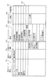
無線ICタグ501は、サービスステージ領域において、図44に示す納品リストテーブル512を有している。納品リストテーブル512は、商品番号と数量と単価と小計との組を複数個記憶する商品情報領域と総金額を記憶する総金額領域とを含む。
【0141】
携帯型リーダライタは、携帯型リーダライタ20を構成する構成要素を含み、さらに、携帯電話型リーダライタ70を構成する発光部325、発光制御部326、受光部328及びコード解読部329を含む。
携帯型リーダライタのテーブル記憶部116は、さらに、図43に示す商品テーブル511を有している。商品テーブル511は、商品番号と商品名と単価とから構成される組を複数個含んでいる。
【0142】
携帯型リーダライタの動作について、図45に示すフローチャートを用いて説明する。
携帯型リーダライタは、操作者からバーコード読み取りを示す操作指示を受け付けると、物品に印刷されているバーコードからバーコード情報を読み取る(ステップS431)。バーコード情報は、商品番号を表示している。携帯型リーダライタは、商品テーブル511から、読み取った前記商品番号と同じ組に含まれている単価を読み出し(ステップS432)、商品番号と単価との組を内部に記憶する(ステップS433)。携帯型リーダライタは、操作者からバーコード読み取りの終了を示す操作指示を受け付けるまで(ステップS434)、前記バーコードの読取りと、単価の読出しと、商品番号と単価との組の記憶とを繰り返す(ステップS431〜ステップS433)。
【0143】
携帯型リーダライタは、操作者からバーコード読み取りの終了を示す操作指示を受け付けると(ステップS434)、記憶している商品番号毎に、商品の数量を集計し(ステップS435)、商品番号毎の単価を合計して小計を算出し(ステップS436)、全ての商品の単価を合計して総金額を算出し(ステップS437)、商品番号毎に、商品番号と、数量と、単価と、小計とからなる組を無線ICタグ501内の納品リストテーブル512の商品情報領域に書込み、総金額を総金額領域に書き込む(ステップS438)。
【0144】
操作者は、物品毎にバーコード読出操作を行って当該物品を格納パレット500に格納し、全ての物品の読出操作が終了すると、集計操作を行う。
3.2 検品システムの構成と動作
検品システムは、格納パレット500と携帯型リーダライタとから構成されている。
【0145】
格納パレット500は、検品システムの格納パレット500と同様の構成である。格納パレット500に付着されている無線ICタグ501は、図44に示す納品リストテーブル512を有している。納品リストテーブル512は、商品番号と数量と単価と小計との組を複数個記憶する商品情報領域と総金額を記憶する総金額領域とを含み、前記商品情報領域は、あらかじめ、商品番号と数量と単価と小計との組を複数個記憶しており、総金額領域は、あらかじめ、総金額を記憶している。
【0146】
携帯型リーダライタは、検品システムの携帯型リーダライタと同様の構成を有する。
携帯型リーダライタの動作について、図46に示すフローチャートを用いて説明する。
携帯型リーダライタは、無線ICタグ501の納品リストテーブル512から、商品番号と数量と単価と小計との全ての組と、総金額とを読み出す(ステップS441)。
【0147】
次に、携帯型リーダライタは、操作者からバーコード読み取りを示す操作指示を受け付けると、物品に印刷されているバーコードからバーコード情報を読み取る(ステップS442)。バーコード情報は、商品番号を表示している。携帯型リーダライタは、読み取った前記商品番号を記憶する(ステップS443)。携帯型リーダライタは、操作者からバーコード読み取りの終了を示す操作指示を受け付けるまで(ステップS444)、前記バーコードの読取りと、商品番号の記憶とを繰り返す(ステップS442〜ステップS443)。
【0148】
携帯型リーダライタは、操作者からバーコード読み取りの終了を示す操作指示を受け付けると(ステップS444)、記憶している商品番号毎に、商品の数量を集計し(ステップS445)、商品番号毎に、前記記憶している数量と集計した前記数量とを比較する。全ての商品番号の数量が一致するなら(ステップS446)、一致することを示すメッセージを表示し(ステップS447)、検品完了を示す「検品完了」を無線ICタグ501へ書き込む(ステップS448)。
【0149】
商品番号の数量の不一致が存在するなら(ステップS446)、携帯型リーダライタは、一致しないことを示すメッセージを表示し(ステップS449)、さらに、数量が不一致の商品番号を全て表示する(ステップS450)。
操作者は、格納パレット500から物品を取り出しながら、物品毎にバーコード読出操作を行い、全ての物品の読出操作が終了すると、集計操作を行う。
3.3 まとめ
以上説明したように、納品システムは、バーコードなどの形象が印刷された印刷媒体と、前記印刷媒体が添付された物品と、電波を用いて非接触に読み書き可能な情報記憶媒体と、物品を格納するための格納籠と、前記情報記憶媒体との間で情報を送受信する携帯情報端末装置とから構成され、物品を納品する際の納品情報を生成する。物品の種類を識別する情報に基づいて形成された形象が印刷された印刷媒体が当該物品の外表面に添付され、前記情報記憶媒体は、前記格納籠に添付されている。
【0150】
前記携帯情報端末装置は、操作者から読出操作、又は集計操作の入力を受け付け、読出操作の入力が受け付けられた場合に、光を用いて物品に添付された前記印刷媒体上の形象を読み出し、読み出した形象に基づいて対応する識別情報を生成し、生成した識別情報を記憶し、集計操作の入力が受け付けられた場合に、記憶している全ての識別情報を読み出し、同じ識別情報毎に識別情報の出現頻度を算出し、算出した前記識別情報毎の出現頻度を電波を用いて送信する。
【0151】
情報記憶媒体は、電波を用いて送信された識別情報毎の出現頻度を受信して、受信した識別情報毎の出現頻度を納品情報として記憶する。
操作者は、物品毎に読出操作を行って当該物品を格納籠に格納し、全ての物品の読出操作が終了すると、集計操作を行う
また、検品システムは、形象が印刷された印刷媒体と、前記印刷媒体が添付された物品と、電波を用いて非接触に読み書き可能な情報記憶媒体と、物品を格納している格納籠と、前記情報記憶媒体との間で情報を送受信する携帯情報端末装置とから構成され、物品を検品する際の検品情報を生成する。物品の種類を識別する情報に基づいて形成された形象が印刷された印刷媒体が当該物品の外表面に添付され、前記情報記憶媒体は、前記格納籠に添付されている。
【0152】
前記情報記憶媒体は、前記格納籠に格納されている物品の種類を識別する識別情報毎の出現頻度を記憶している。
前記携帯情報端末装置は、操作者から読出操作、又は集計操作の入力を受け付け、読出操作の入力が受け付けられた場合に、光を用いて物品に添付された前記印刷媒体上の形象を読み出し、読み出した形象に基づいて対応する識別情報を生成し、生成した識別情報を記憶する。集計操作の入力が受け付けられた場合に、記憶している全ての識別情報を読み出し、同じ識別情報毎に識別情報の出現頻度を算出し、前記情報記憶媒体から前記識別情報毎の出現頻度を電波を用いて受信し、識別情報毎に、算出した出現頻度と受信した出現頻度とを比較し、比較結果を検品情報として出力する。
【0153】
操作者は、格納籠から物品を取り出しながら、物品毎に読出操作を行い、全ての物品の読出操作が終了すると、集計操作を行う。
4 第4の実施の形態
本発明の別の1の実施の形態としてのコンピュータゲームシステム及び販売システムについて説明する。
4.1 コンピュータゲームシステムの構成及び動作
コンピュータゲームシステムは、コンピュータゲーム機と非接触CD−ROM561とから構成される。
【0154】
コンピュータゲーム機は、図47(a)にその外観図を示すように、ディスプレィ部551と本体部552とコントローラ553とから構成されている。
本体部552は、マイクロプロセッサとコンピュータプログラムが記憶されているROMとRAMとCD−ROM入出力部とを含む。さらに、本体部552は、携帯型リーダライタ20の構成要素である変復調部、命令生成部、命令解読部、制御部、双方向認証部、テーブル記憶部、タグタイプ記憶部を含む。また、コントローラ553は、複数のボタンとアンテナ部554を備えている。アンテナ部554は、携帯型リーダライタ20の構成要素であるアンテナ部と同様である。
【0155】
非接触CD−ROM561は、図47(b)にその外観図を示す。非接触CD−ROM561は、中空円盤形状を有し、前記中空円盤内に、光により情報の書込み又は読み出しがされる中空円状の記録部564を備えている。また、前記円盤の外円周の近辺内側に沿って円状に貼られた導線からなるアンテナ部562を備え、前記円盤の内円周の近辺外側にチップ部563を備え、アンテナ部562とチップ部563とは接続されている。チップ部563は、図13にしめす無線ICタグ10bの構成要素である復調部202、変調部203、電源部204、命令解読部205、タグタイプ記憶部206、制御部207、識別コード記憶部208、入出力部209及びメモリ部210を含んでいる。
【0156】
メモリ部210に記憶されている情報の一例を図48に示す。メモリ部210は、生産ステージ領域572と物流ステージ領域573と販売ステージ領域574とサービスステージ領域575と回収リサイクルステージ領域576と共通領域577とから構成され、生産ステージ領域572は、「ゲームソフトメーカ名」と「ゲーム名」と「版数」と「品番」と「制作日」とを記録しており、 物流ステージ領域573は、「運送業者名」を記録しており、販売ステージ領域574は、「卸業者名」と「小売店名」と「販売日」と正当に販売されたか否かを示す「販売情報」とを記録しており、サービスステージ領域575は、「課金情報」と「使用権利情報」と「使用回数」と「使用権利者名」と「ゲーム経過情報」と「キャラクタパワー情報」と「ゲーム改訂情報アドレス」と「使用権利者パスワード」と「サービスセンタ電話番号」とを記録しており、回収リサイクルステージ領域576は、「リユース記録」とを記録している。共通領域577に記録されている情報はない。
【0157】
コンピュータゲームシステムの動作について、図49及び図50に示すフローチャートを用いて説明する。
コンピュータゲーム機は、課金情報と使用権利情報と使用回数と使用権利者パスワードを非接触CD−ROM561内のチップ部563が有するメモリ部210から読み出す(ステップS471)。コンピュータゲーム機は、操作者から使用権利者パスワードの入力を受け付け(ステップS472)、読み出した使用権利者パスワードと入力を受け付けた使用権利者パスワードとを比較して、一致しないならば(ステップS473)、一致しないことを示すメッセージを表示して(ステップS474)、終了する。
【0158】
使用権利者パスワードが一致しているならば(ステップS473)、課金情報の残高を確認し、残高が無いなら(ステップS475)、残高が無いことを示すメッセージを表示して(ステップS476)、終了する。
課金情報の残高があるなら(ステップS475)、使用回数の残を確認し、残が無いなら(ステップS477)、残が無いことを示すメッセージを表示して(ステップS478)、終了する。
【0159】
使用回数の残があるなら(ステップS477)、使用権利情報を確認し、使用権利情報が正式に購入したことを示す正式版であるなら(ステップS479)、課金情報及び使用回数を減じ、課金情報及び使用回数をメモリ部210に上書きする(ステップS480)。
次に、ゲーム経過情報とキャラクタパワー情報とをメモリ部210から読み出し(ステップS481)、非接触CD−ROM561の記録部564からゲームプログラムを読み出し、読み出したゲーム経過情報とキャラクタパワー情報とに基づいて、前記ゲームプログラムを起動する(ステップS482)。ゲーム経過情報は、ゲームを再開する位置を示す情報を含み、この位置からゲームプログラムが再開される。使用権利情報に基づいて、ゲームプログラムが実行され(ステップS483)、操作者によるゲーム終了を示す操作指示が受け付けられると(ステップS484)、現時点のゲーム経過情報と現時点のキャラクタパワー情報とをメモリ部210に上書きする(ステップS485)。
【0160】
なお、次のようにしてもよい。コンピュータゲーム機は、家庭内LANを介して、インターネットに接続されている。家庭内LANは、各種家電機器や家庭内サーバ機としてのパソコンを接続している。また、ゲームメーカーが運営するゲームソフトサーバ機がインターネットに接続されており、ゲームソフトの改訂に関する情報を記憶している。ゲームソフトサーバ機のインターネット上のアドレスが、非接触CD−ROM561のメモリ部210にゲーム改訂情報アドレスとして記憶されている。
【0161】
コンピュータゲーム機は、非接触CD−ROM561のメモリ部210からゲーム改訂情報アドレスを読み出し、読み出したゲーム改訂情報アドレスを用いて、インターネットを介して、ゲームソフトサーバ機に接続し、接続したゲームソフトサーバ機から、ゲームソフトの改訂に関する情報を取り出し、取り出した情報を用いて、ゲームプログラムを実行する。
4.2 販売システム
販売システムは、入金処理を行うキャッシュレジスタ装置と非接触CD−ROM561とから構成される。
【0162】
販売管理装置であるキャッシュレジスタ装置は、携帯型リーダライタ20の構成要素であるアンテナ部、変復調部、命令生成部、命令解読部、制御部、双方向認証部、テーブル記憶部及びタグタイプ記憶部などを含み、非接触CD−ROMを販売する販売店に設置されて販売者により操作される。
非接触CD−ROM561は、前記コンピュータゲームシステムにおける非接触CD−ROM561と同じである。
【0163】
非接触CD−ROM561が、販売店において正当に購入されると、販売者の操作により、キャッシュレジスタ装置は、支払いのされた金額に相当する額の課金情報と、正式版であることを示す使用権利情報と、前記課金情報に見合った使用回数とを非接触CD−ROM561のメモリ部210に上書きする。また、正当に販売されたことを示す販売情報をメモリ部210に上書きする。
4.3 万引防止装置
万引防止装置は、前記販売店の入り口に設置され、携帯型リーダライタ20の構成要素であるアンテナ部、変復調部、命令生成部、命令解読部、制御部、双方向認証部、テーブル記憶部及びタグタイプ記憶部などを含む。
【0164】
万引防止装置は、非接触CD−ROM561のメモリ部210から販売情報を読み出し、読み出した販売情報が正当に販売されていないことを示す場合に、万引防止装置は、警報を発する。
このようにして、正当に販売されていない非接触CD−ROMが販売店の入り口から持ち出された場合に、入れ口に設置された万引防止装置は、警報を発するので、万引の防止ができる。
4.4 その他の変形例
上記において、コンピュータゲーム機と非接触CD−ROMの例を示しているが、前記非接触CD−ROMは、CD、DVD、DVD−ROM、DVD−RAMなどの光ディスク媒体であるとしてもよい。これらの光ディスク媒体は、非接触CD−ROMと同様に、アンテナ部562とチップ部563とを備えている。
【0165】
これらの光ディスク媒体には、映画、静止画、動画、音声などの情報が記録されていおり、これらの光ディスク媒体を再生する光ディスク媒体再生装置(一例は、DVDプレーヤ)は、前記コンピュータゲーム機と同様に、光ディスク媒体のチップ部563に記録されている権利情報などを用いて、これらの映画、静止画、動画、音声などの情報を再生するとしてもよい。
【0166】
また、光ディスク媒体再生装置を利用者が操作するためのリモコンが、携帯型リーダライタ20と同様の構成を有しており、光ディスク媒体再生装置及びホストコンピュータ装置がインターネットに接続されており、リモコンは、無線ICタグ又は非接触CD−ROMにアクセスし、アクセス結果を赤外線又は無線通信(例えば、2.4GHz帯のスペクトル拡散を使用する通信)を用いて前記光ディスク媒体再生装置へ出力し、さらにインターネットを介して前記ホストコンピュータ装置へ送信するとしていもよい。
4.5 まとめ
以上説明したように、光を用いて情報の読み書きが可能な光ディスク媒体は、半導体メモリを備え、電波を用いてアクセス要求を受信し、受信したアクセス要求に応じて前記半導体メモリにアクセスし、アクセス結果を電波を用いて送信する。
【0167】
また、前記光ディスク媒体から情報を読み出して再生する光ディスク媒体再生装置は、電波を用いてアクセス要求を送信し、アクセス要求に応じたアクセス結果を電波を用いて受信し、アクセス結果に含まれる権利情報に基づいて、前記光ディスク媒体から光を用いて読み書きが可能な情報の再生が許可されるか否かを判断し、判断結果に基づいて、前記情報を読み出して再生する。
5 第5の実施の形態
本発明の別の1の実施の形態としての電波を用いて非接触に読み書き可能な情報記憶媒体について説明する。
5.1 無線ICタグの構成
電波を用いて非接触に読み書き可能な情報記憶媒体としての無線ICタグは次に示すように形成してもよい。
【0168】
無線ICタグ591は、図51(a)に示すように、長さ3mm、幅0.5mm、厚さ0.5mmの板状に成形された樹脂595内に、半導体部594が封入されて形成されている。半導体部594は、長さ2mm、幅4mm、厚さ0.2mmの板形状を有し、IC部592とアンテナ部593とから構成される大規模集積回路(LSI)である。
【0169】
無線ICタグ591は、UHF帯(すなわち、868MHz、915MHz)、2.4GHz帯、5GHz帯の通信周波数を用いる。UHF帯以上の無線ICタグでは、そのアンナテ寸法は、略半波長又は1/4波長でよく、比較的小さいので、このように同一半導体のチップ上にアンテナと機能素子とを形成できる。こうして、小型化、工数削減(低コスト化)、高信頼化(接続部の高信頼化)を実現できる。
【0170】
例えば、2.4GHz帯の無線ICタグの場合、長さ3cm、幅0.5mmで、メモリ等の機能素子の上にアンテナを形成し、裏面にアンテナを形成したものを試作した。
IC部592は、図13に示す無線ICタグ10bを構成する復調部202、変調部203、電源部204、命令解読部205、タグタイプ記憶部206、制御部207、識別コード記憶部208、入出力部209、メモリ部210及び認証部211aを含む。アンテナ部593は、アンテナ部201と同じである。
【0171】
また、無線ICタグは次に示すように形成してもよい。
無線ICタグ598は、図51(b)に示すように、長さ3mm、幅2mm、厚さ0.5mmの板状に成形された樹脂596内に、半導体部597が封入されて形成されている。半導体部597は、長さ0.4mm、幅0.3mm、厚さ0.2mmの板形状を有し、機能素子とパッチアンテナとを同一半導体チップ上に形成し、図13に示す無線ICタグ10bを構成するアンテナ部201、復調部202、変調部203、電源部204、命令解読部205、タグタイプ記憶部206、制御部207、識別コード記憶部208、入出力部209、メモリ部210及び認証部211aを含む。
5.2 無線ICカードの構成
電波を用いて非接触に読み書き可能な情報記憶媒体としての無線ICカードは次に示すように形成してもよい。
【0172】
無線ICカード609aは、125KHz帯及び13MHz帯域の周波数の電波を受信し、図52(a)にその外観を示し、図53に回路ブロック図を示すように、長さ70mm、幅40mm、厚さ1mmの板状に成形された樹脂605a内に、ICチップ部601と共振用のコンデンサ602aと電源用のコンデンサ603aとコイル状のアンテナであるコイル604aが封入されて形成されている。
【0173】
コンデンサ602a及び603aは、それぞれICチップ部601に接続されている。コンデンサ602a及び603aのキャパシタンスC1及びC2は、それぞれ、75pF及び500pFである。
コイル604aは、樹脂605aの内部であって樹脂605aの外周に近接した周状部において、絶縁体が被覆された1本の導線が前記外周に沿ってコイル状に3〜4回巻かれ、前記コイルにより形成される面と樹脂605aの板状面とが略一致するように形成されており、前記導線の両端は、ICチップ部601に接続されている。コイル604aのインダクタンスLは、1.7μHである。
【0174】
ICチップ部601は、整流部と変調部203と復調部202とクロック生成部と命令解読部205とタグタイプ記憶部206と制御部207と識別コード記憶部208と入出力部209とメモリ部210とを含んでいる。
詳細の仕様については、以下のとおりである。1KビットのFeRAMのメモリ、変調方式(タグからリーダライタへは、BPSK、リーダライタからタグへは、ASK)、独自方式のプロトコル、NRZのビットコーディング、CRCのエラーチェック、半二重の通信方式。
【0175】
コイル604aとコンデンサ602aとは、並列して接続されてアンテナを形成し、その両端は、それぞれ、整流部、変調部203、復調部202及びクロック生成部に接続されており、コイル604aとコンデンサ602aとから形成されるアンテナは、電波を受信し、受信した電波を電力信号に変換して、整流部、変調部203、復調部202及びクロック生成部へ供給する。
【0176】
コンデンサ603aは、整流部を介して電力信号を受け取り、受け取った電力信号を電荷として蓄積する。また、無線ICカード609aの各構成部に電力を供給する。
変調部203、復調部202、命令解読部205、タグタイプ記憶部206、制御部207、識別コード記憶部208、入出力部209及びメモリ部210は、図11に示す無線ICタグ10aを構成する構成要素と同じである。また、クロック生成部は、基準となるクロックを生成し、各構成要素に供給する。
【0177】
また、無線ICカードは次に示すように形成してもよい。
無線ICカード609bは、125KHz帯域の周波数の電波を受信し、図52(b)にその外観を示すように、樹脂605b内に、ICチップ部601と共振用のコンデンサ602bと電源用のコンデンサ603bとコイル状のアンテナであるコイル604bが封入されて形成されている。
【0178】
コンデンサ602b及び603bのキャパシタンスC1及びC2は、それぞれ、1000pF及び40000pFである。また、コイル604bのインダクタンスLは、1.6mHであり、巻き数は、50巻である。その他の点については、無線ICカード609aと同様であるので説明を省略する。
このように、無線ICカード609aと無線ICカード609bにおいて、ICチップ部601は同じであり、共振用のコンデンサ及び電源用のコンデンサのキャパシタンス、コイルのインダクタンス及び巻き数が異なる。
【0179】
このように、機能素子を含むチップ部を共通にし、外付けのアンテナ、コンデンサにより周波数を調整することにより、複数種類の周波数帯域で通信できる無線ICカードを製造することができる。
6 第6の実施の形態
本発明の別の1の実施の形態としてのアクセスシステムについて説明する。
【0180】
このアクセスシステムは、床下に配線されたコンピュータのLANケーブルや電話線に添付された無線ICタグ10dと、携帯型リーダライタ20とから構成され、床下に配線されたコンピュータのLANケーブルや電話線の種類などを床上から知るために用いられる。
ここで、携帯型リーダライタ20は、図2に示す携帯型リーダライタ20と同様であるので、説明を省略する。
6.1 無線ICタグ10dの構成
無線ICタグ10dは、図54に示すように、アンテナ部201a、201b、復調部202a、202b、変調部203a、203b、電源部204、命令解読部205、タグタイプ記憶部206、制御部207、識別コード記憶部208、入出力部209及びメモリ部210から構成されている。
【0181】
これらの構成要素は、図11に示す無線ICタグ10aの構成要素とほぼ同様であるので、以下において、異なる点についてのみ説明を行う。
アンテナ部201a、復調部202a及び変調部203aは、125KHz帯域の周波数の電波を受信し、また反射する。ここで、復調部202aは、復調部202aであることを識別情報を復調した情報に付加して、命令解読部205へ出力し、命令解読部205は、識別情報をそのまま制御部207へ出力する。
【0182】
アンテナ部201b、復調部202b及び変調部203bは、2.4GHz帯域の周波数の電波を受信し、また反射する。ここで、復調部202bは、復調部202bであることを識別情報を復調した情報に付加して、命令解読部205へ出力し、命令解読部205は、識別情報をそのまま制御部207へ出力する。
タグタイプ記憶部206は、タグタイプとして、125KHz帯域及びフリーアクセスプロトコルの組と、2.4GHz帯域及びフリーアクセスプロトコルの組とを記憶している。
【0183】
メモリ部210は、図55に示すように、上記のケーブルや電話線などの「線の種類情報」と、線が接続する物と物との関係を示す「系統」と、線を識別する「ID」と、線が配置されている位置を識別する「線の位置」とを記憶している。
制御部207は、アンテナ部201a、復調部202a及び命令解読部205を介して携帯型リーダライタ20から送信された命令と、復調部202aを識別する識別情報とを受け取る。また、アンテナ部201b、復調部202b及び命令解読部205を介して携帯型リーダライタ20から送信された命令と、復調部202bを識別する識別情報とを受け取る。
【0184】
復調部202aを識別する識別情報とを受け取った場合には、制御部207は、以降は、アンテナ部201a、復調部202a及び変調部203aを介して、携帯型リーダライタ20と通信を行う。復調部202bを識別する識別情報とを受け取った場合には、以降は、アンテナ部201b、復調部202b及び変調部203bを介して、携帯型リーダライタ20と通信を行う。また、復調部202aを識別する識別情報と復調部202bを識別する識別情報の両方を受け取った場合には、以降は、アンテナ部201a、復調部202a及び変調部203aを介して、携帯型リーダライタ20と通信を行う。
6.2 アクセスシステムの動作
アクセスシステムの動作について、図56に示すフローチャートを用いて説明する。
【0185】
携帯型リーダライタ20は、アクセス要求命令を生成し(ステップS501)、3種類の周波数の電波により生成したアクセス要求命令を送信し(ステップS502)、無線ICタグ10dは、2種類又は1種類の周波数の電波によりアクセス要求命令を受信しする(ステップS503)。無線ICタグ10dは、次に、識別情報を抽出し、受信したアクセス要求命令を解読し(ステップS504)、抽出した識別情報に該当するタグタイプを読み出し(ステップS505)、読み出したタグタイプを含むタグタイプ送信命令を生成し(ステップS506)、生成したタグタイプ送信命令を電波を反射することにより送信する(ステップS507〜S508)。携帯型リーダライタ20は、タグタイプ送信命令を受信して、用いる周波数帯域とプロトコルタイプとを決定し(ステップS509)、無線ICタグ10dから線の種類に関する情報を読み出す旨のアクセス命令を生成し(ステップS510)、電波により生成したアクセス命令を送信し、無線ICタグ10dは、前記アクセス命令を受信する(ステップS511)。無線ICタグ10dは、メモリ部210にアクセスして線の種類に関する情報を読み出し(ステップS512)、読み出した線の種類に関する情報を含むアクセス応答命令を生成し(ステップS513)、生成したアクセス応答命令を電波により送信し(ステップS514)、携帯型リーダライタ20は、アクセス応答命令を受け取る(ステップS515)。
6.3 まとめ
オフィスに複数台設置されているコンピュータやプリンタなどを接続する複数の配線毎に、前記配線が接続する機器と機器とを示す情報などが記録されている無線ICタグを添付し、これらの複数の配線をオフィスの床下に埋め込む。
【0186】
リーダライタを床上から操作して、これらの無線ICタグに記録されている情報を読み出すことにより、機器と機器とを接続する配線に関する情報を知ることができる。
125KHz帯域の周波数の電波は、無線ICタグ10dに金属が近接していると、前記金属に吸収され、無線ICタグ10dは、前記電波を受信できない。また、2.4KHz帯域の周波数の電波は、無線ICタグ10dと携帯型リーダライタ20との間に水分が存在すると、前記金属に吸収され、無線ICタグ10dは、前記電波を受信できない。
【0187】
無線ICタグ10dは、125KHz帯域及び2.4GHz帯域の周波数の電波を受信することができるので、上記のような状態であっても、無線ICタグ10dと携帯型リーダライタ20との間で通信できる可能性が高くなる。
アクセス装置の一例は、情報記憶媒体が添付された物品の位置を管理する物品位置管理装置である。情報記憶媒体は、当該物品を識別する物品識別子と当該物品が空間上に配置されている位置を識別する位置識別子とを記憶している。アクセス装置は、情報記憶手段に記憶されている物品識別子と位置識別子とを読み出す指示を示すアクセス要求を生成し、前記読み出す指示を示すアクセス要求を送信する。情報記憶媒体は、前記読み出す指示を示すアクセス要求を受信し、内部からアクセス結果情報として物品識別子と位置識別子とを読み出し、物品識別子と位置識別子とを送信する。アクセス装置は、物品識別子と位置識別子とを受信する。
【0188】
このように、無線ICタグを物品に添付することにより、物品の位置管理を行うことができる。
なお、無線ICタグが狭い範囲内に複数コンピュータある場合に、無線ICタグから記憶されている情報を正確に読み出すために、リーダライタは、衝突防止機能を有している。
7 第7の実施の形態
本発明の別の1の実施の形態としての無線ICタグ10について説明する。
【0189】
無線ICタグ10は、第1の実施の形態において説明した無線ICタグと同じてあり、電波を用いて非接触に読み書き可能な情報記憶媒体であって、取り外し自在に物品に添付される。
図57に示すように、物品651はその外表面上に、無線ICタグ10が嵌合するように凹状に設けられた凹部652を有し、凹部652の底面に4個のネジ穴653が穿設されている。
【0190】
無線ICタグ10は、4個のネジ穴653に対応して、穿設された4個の穴654を有する。無線ICタグ10は、凹部652と嵌合し、4個のネジ655により固定されている。
ロゴが表面に印刷された板状の部材656が、凹部652と嵌合する無線ICタグ10を覆うように、物品651の外表面に接着剤により固定されている。
【0191】
このように、無線ICタグ10はネジにより物品に固定されているので、容易に取り外すことができる。
こうして、無線ICタグの添付されている物品のリサイクル時に、物品に添付されて無線ICタグを物品から分離・取り出しが容易にできる。
8 第8の実施の形態
本発明の別の1の実施の形態としての電磁調理システムについて説明する。
【0192】
この電磁調理システムは、調理方法の記録されている無線ICタグ672が添付された食材容器671と、電磁調理装置とから構成され、電磁調理装置は、無線ICタグ672から調理方法を読み出し、調理方法に基づいて、食材を調理する。
図58(a)に示すように、食材容器671は、外表面に無線ICタグ672が添付されており、内部に食材が入れられている。
【0193】
無線ICタグ672は、図12に示すように、生産ステージ領域において、食材を識別する「品名」と「品番」とを記憶している。
電磁調理装置は、一例として、電子レンジであり、携帯型リーダライタ20と同様の構成を内蔵している。また、様々な食材について、食材の品番と、当該食材に応じた調理方法との組を記憶している。ここで、調理方法の一例は、電磁調理装置が照射する電磁波の照射時間である。無線ICタグ10の添付された食材容器が電磁調理装置の内部に利用者により入れられると、電磁調理装置は、無線ICタグ10の生産ステージ領域に記録されている「品番」を読み出し、次に、読み出した品番に対応する照射時間を読み出し、読み出した照射時間中、電磁波を間に食材容器に対して照射する。
【0194】
なお、無線ICタグ10は、調理方法として「照射時間」を記憶しており、電磁調理装置は、無線ICタグ10から「照射時間」を読み出し、読み出した「照射時間」中、電磁波を食材容器に対して照射するとしてもよい。
また、調理方法の一例は、電磁調理装置が照射する電磁波の照射時間と電磁波の強度であるとしてもよい。
【0195】
このように、無線ICタグを加工食品を含む食品の包装容器に埋め込み、この無線ICタグと通信できるリーダライタを電化調理器に設ける。無線ICタグは、最適な調理条件や調理の好みに応じた複数種類の調理条件を記憶しており、電化調理器は、最適な調理条件を用いて、又は利用者から調理の好みの入力を受け付けて好みに対応する調理条件を読み出し、読み出した調理条件を用いて、これらの食品を調理する。
9 第9の実施の形態
本発明の別の1の実施の形態としての洗濯システムについて説明する。
【0196】
この洗濯システムは、洗濯方法が記録されている無線ICタグ683が添付された衣服681と、家庭用電気洗濯機とから構成され、家庭用電気洗濯機は、無線ICタグ683から洗濯方法を読み出し、読み出した洗濯方法に基づいて衣服681を洗濯する。
図58(b)に示すように、ラベル684の裏面に無線ICタグ683が貼り付けられ、無線ICタグ683が貼り付けられたラベル684が衣服681の襟裏側部682に縫い付けられる。
【0197】
衣服681に付されている無線ICタグ683は、図12に示すように、サービスステージ領域において、「洗濯方法」と「洗濯回数」とを記憶している。
家庭用電気洗濯機は、携帯型リーダライタ20と同様の構成を内蔵している。また、様々な洗濯方法に応じた洗濯コースを記憶している。衣服681が家庭用電気洗濯機の洗濯槽内に入れられると、家庭用電気洗濯機は、無線ICタグ683のサービスステージ領域に記録されている「洗濯方法」と「洗濯回数」とを読み出し、家庭用電気洗濯機は、読み出した洗濯方法に応じた洗濯コースを読み出し、さらに読み出した「洗濯回数」により、読み出した洗濯コースを変更し、変更された洗濯コースに基づいて、衣服681の洗濯を開始する。ここで、「洗濯回数」による洗濯コースの変更の具体例は、「洗濯回数」が多い場合には、衣服681の生地がかなり傷んでいると考えられるので、洗濯槽の回転をゆっくりとすることであり、「洗濯回数」が少ない場合には、衣服681の生地の痛みが少ないと考えられるので、洗濯槽の回転を激しくすることである。洗濯が終了すると、家庭用電気洗濯機は、読み出した「洗濯回数」に1の値を加算し、1が加算された「洗濯回数」を無線ICタグ683のサービスステージ領域に上書きする。
【0198】
このようして、洗濯物のライフサイクル管理や長寿命化を図ることができる。
10 その他の変形例
なお、本発明を上記実施の形態に基づいて説明してきたが、本発明は上記実施の形態に限定されないのはもちろんである。すなわち、以下のような場合も本発明に含まれる。
(1)無線ICタグに、さらに、温度センサ、圧力センサなどのセンサを付加し、これらのセンサにより、定期的に、無線ICタグの周辺の温度、圧力などを検出し、検出した温度、圧力などを無線ICタグ内に記録するようにしてもよい。こうして、製品の製造時から使用時までの温度及び圧力の履歴を管理する。また、この無線ICタグは、これらのセンサを駆動させるため電池を備えているとしてもよい。リーダライタからの呼びかけに応じて、その履歴データを通信する。
【0199】
具体的には、生産物をある一定温度範囲、圧力範囲に保つ必要がある応用装置であり、機能素子から構成されるチップ部は、メモリ機能や無線通信機能の他に、A/Dコンバータを内蔵し、センサ素子の信号をデジタル化してチップのメモリに時々刻々取り込む。
なお、無線ICタグは、温度センサ又は圧力センサのどちらか一方を有するとしてもよい。
【0200】
また、電池を備えず、電源としてリーダライタから送信される電波を電力として蓄積するパッシブタイプの無線ICタグであるとしてもよい。この場合には、リーダライタから電波が送信されている間に、センシングし、そのデータを蓄積又は送信する。このように構成すると電池交換が不要となる。
(2)冷蔵庫の外装ケースに凹部を形成し、そこに無線ICタグを埋め込む。無線ICタグが埋め込まれた位置を知らせるために、目印のシール、又は環境適用マークであるグリーンシールを、その位置又はその近傍位置に貼るようにしてもよい。この場合、埋め込み位置がすぐに確認できるので、リーダライタによる読み書きの狙い位置とできる。
【0201】
また、製品の外装ケースに無線ICタグを埋め込み、無線ICタグの埋め込まれた位置又は近傍位置に、マークを添付するようにしてもよい。マークは、バーコード、2次元コード又は文字のいずれかである。リーダライタは、携帯型リーダライタ20と同様の構成を有する。さらに、前記マークが添付されている位置を含む広い範囲を走査する光学式の読取部を備え、前記マークが添付されている位置を検出する。また、リーダライタは、指向性を有するアンテナを備え、前記検出された位置に指向性を向けて電波を送信する。
(3)本発明は、本実施の形態に示す方法であるとしてもよい。
【0202】
また、これらの方法をコンピュータにより実現するコンピュータプログラムであるとしてもよいし、前記コンピュータプログラムからなるデジタル信号であるとしてもよい。
また、本発明は、前記コンピュータプログラム又は前記デジタル信号をコンピュータ読み取り可能な記録媒体、例えば、フロッピーディスク、ハードディスク、CD―ROM、MO、DVD、DVD−ROM、DVD−RAM、半導体メモリなど、に記録したものとしてもよい。また、これらの記録媒体に記録されている前記コンピュータプログラム又は前記デジタル信号であるとしてもよい。
【0203】
また、本発明は、前記コンピュータプログラム又は前記デジタル信号を、電気通信回線、無線又は有線通信回線、インターネットを代表とするネットワーク等を経由して伝送するものとしてもよい。
(4)本発明は、上記に示す実施の形態、複数の変形例、又は上記実施の形態及び複数の変形例の一部を組み合わせるとしてもよい。
【0204】
【発明の効果】
上記に説明したように、本発明は、電波を用いて非接触に読み書き可能な情報記憶媒体と前記情報記憶媒体との間で電波を用いて情報を送受信するアクセス装置とから構成されるアクセスシステムであって、前記アクセス装置は、それぞれ異なる周波数の電波により情報を送信する複数の装置送信手段と、前記複数の周波数とそれぞれ同一の周波数の電波により送信される情報を受信する複数の装置受信手段と、前記複数の装置送信手段に対して、一の時間帯において前記情報記憶媒体に対するアクセスの開始を示すアクセス要求情報を送信するように制御する装置制御手段とを備え、前記情報記憶媒体は、前記アクセス装置の送信する周波数のうちの1と同一の周波数の電波により前記アクセス要求情報を受信する媒体受信手段と、前記受信する周波数と同一の周波数の電波により情報を送信する媒体送信手段と、前記アクセス要求情報を受信すると、前記アクセス要求情報に対する応答を示すアクセス応答情報を送信するように、前記媒体送信手段に対して制御する媒体制御手段とを備える。
【0205】
この構成によると、情報記憶媒体の受信できる周波数帯域が異なる場合であっても、アクセス装置は、前記情報記憶媒体との間で通信を行えるという効果がある。
ここで、前記情報記憶媒体は、さらに、前記媒体受信手段が受信する周波数を識別する周波数識別子を記憶しているタイプ記憶手段を有し、前記媒体制御手段は、前記タイプ記憶手段から周波数識別子を読み出し、読み出した周波数識別子を含むアクセス応答情報を送信するように制御し、前記複数の装置受信手段のうちの1の装置受信手段は、前記アクセス応答情報を受信し、前記装置制御手段は、さらに、受信したアクセス応答情報に含まれる周波数識別子により識別される周波数を用いる前記装置送信手段及び前記装置受信手段に対して、それぞれ送信及び受信を行うように制御する。
【0206】
この構成によると、情報記憶媒体から周波数識別子が送信されるので、以降は、この周波数識別子による識別される周波数帯域を用いて、アクセス装置と、情報記憶媒体との間で通信を行えるという効果がある。
ここで、前記アクセス装置は、さらに、前記アクセス装置により用いられる複数の通信手順をそれぞれ示す通信手順識別子を記憶している通信手順記憶手段を有し、前記タイプ記憶手段は、さらに、前記情報記憶媒体が用いる1の通信手順を識別する通信手順識別子を含み、前記媒体制御手段は、さらに、前記タイプ記憶手段から通信手順識別子を読み出し、読み出した通信手順識別子を含むアクセス応答情報を送信するように制御し、前記通信手順識別子により識別される通信手順により前記アクセス装置との間の通信を制御し、前記複数の装置受信手段のうちの1の装置受信手段は、前記アクセス応答情報を受信し、前記装置制御手段は、さらに、受信したアクセス応答情報に含まれる通信手順識別子により識別される通信手順を前記通信手順記憶手段から読み出し、読み出した通信手順を用いて前記情報記憶媒体との間の通信を制御する。
【0207】
この構成によると、情報記憶媒体から通信手順識別子が送信されるので、以降は、この通信手順識別子による識別される通信手順を用いて、アクセス装置と情報記憶媒体との間で通信を行えるという効果がある。
ここで、前記通信手順識別子により識別される通信手順は、アクセス装置と情報記憶媒体との間で認証手続きを伴わずにアクセスを許可するフリーアクセス手順であり、前記情報記憶媒体は、情報を記憶する領域を有する記憶手段を含み、前記装置制御手段は、前記周波数識別子により識別される周波数を用いる前記装置送信手段に対して、情報記憶媒体へのアクセスを指示するアクセス命令を送信するように制御し、前記媒体受信手段は、さらに、前記アクセス命令を受信し、前記媒体制御手段は、さらに、受信した前記アクセス命令に従って、前記記憶手段にアクセスし、前記アクセスにより得られる情報を示すアクセス結果情報を送信するように前記媒体送信手段に対して制御し、前記周波数識別子により識別される周波数を用いる前記装置受信手段は、さらに、前記アクセス結果情報を受信する。
【0208】
この構成によると、前記通信手順は、フリーアクセス手順であるので、アクセス装置と情報記憶媒体との間で自由に通信を行えるという効果がある。
ここで、前記通信手順識別子により識別される通信手順は、前記アクセス装置と前記情報記憶媒体との間の双方向認証が成功した場合にアクセスを許可する双方向認証手順であり、前記情報記憶媒体は、情報を記憶する領域を有する記憶手段を含み、前記アクセス装置と前記情報記憶媒体とは、相互に認証を行い、前記装置制御手段は、相互の認証が成功した場合に、前記周波数識別子により識別される周波数を用いる前記装置送信手段に対して、情報記憶媒体へのアクセスを指示するアクセス命令を送信するように制御し、前記媒体受信手段は、さらに、相互の認証が成功した場合に、前記アクセス命令を受信し、前記媒体制御手段は、さらに、受信した前記アクセス命令に従って、前記記憶手段にアクセスし、前記アクセスにより得られる情報を示すアクセス結果情報を送信するように前記媒体送信手段に対して制御し、前記周波数識別子により識別される周波数を用いる前記装置受信手段は、さらに、前記アクセス結果情報を受信する。
【0209】
この構成によると、前記通信手順は、双方向認証手順であり、アクセス装置と情報記憶媒体との間で、互いに認証が成功した場合にのみ、通信を行うので、情報が不正に利用されることを防ぐことができる。
ここで、前記通信手順識別子により識別される通信手順は、前記情報記憶媒体が前記アクセス装置を認証する片方向認証が成功した場合にアクセスを許可する片方向認証手順であり、前記情報記憶媒体は、情報を記憶する領域を有する記憶手段を含み、前記情報記憶媒体は前記アクセス装置の認証を行い、前記装置制御手段は、認証が成功した場合に、前記周波数識別子により識別される周波数を用いる前記装置送信手段に対して、情報記憶媒体からの情報の読み出しを指示する読出命令を含むアクセス命令を送信するように制御し、前記媒体受信手段は、さらに、認証が成功した場合に、前記アクセス命令を受信し、前記媒体制御手段は、さらに、受信した前記アクセス命令に含まれる読出命令に従って、前記記憶手段にアクセスし、前記アクセスにより得られる情報を示すアクセス結果情報を送信するように前記媒体送信手段に対して制御し、前記周波数識別子により識別される周波数を用いる前記装置受信手段は、さらに、前記アクセス結果情報を受信する。
【0210】
この構成によると、前記通信手順は、片方向認証手順であり、情報記憶媒体がアクセス装置を認証し、正当なアクセス装置のみが情報記憶媒体にアクセスするので、正当なアクセス装置へのみ情報を出力できる。
ここで、前記通信手順識別子により識別される通信手順は、アクセス装置が情報記憶媒体を認証する片方向認証が成功した場合にアクセスを許可する片方向認証手順であり、前記情報記憶媒体は、情報を記憶する領域を有する記憶手段を含み、前記アクセス装置は前記情報記憶媒体の認証を行い、前記装置制御手段は、認証が成功した場合に、前記周波数識別子により識別される周波数を用いる前記装置送信手段に対して、情報記憶媒体への情報の書き込みを指示する書込命令を含むアクセス命令を送信するように制御し、前記媒体受信手段は、さらに、認証が成功した場合に、前記アクセス命令を受信し、前記媒体制御手段は、さらに、受信した前記アクセス命令に含まれる書込命令に従って、前記記憶手段にアクセスし、前記アクセスにより得られる情報を示すアクセス結果情報を送信するように前記媒体送信手段に対して制御し、前記周波数識別子により識別される周波数を用いる前記装置受信手段は、さらに、前記アクセス結果情報を受信する。
【0211】
この構成によると、前記通信手順は、片方向認証手順であり、アクセス装置が情報記憶媒体を認証し、アクセス装置が正当な情報記憶媒体にのみアクセスするので、正当な情報記憶媒体へのみ情報を出力できる。
また、本発明は、電波を用いて非接触に読み書き可能な情報記憶媒体と前記情報記憶媒体との間で電波を用いて情報を送受信するアクセス装置とから構成されるアクセスシステムであって、前記アクセス装置は、それぞれ異なる周波数の電波により情報を送信する複数の装置送信手段と、前記複数の周波数とそれぞれ同一の周波数の電波により送信される情報を受信する複数の装置受信手段と、前記複数の装置送信手段に対して、それぞれ異なる時間帯において時系列的順序により前記情報記憶媒体に対するアクセスの開始を示すアクセス要求情報を送信するように制御する装置制御手段とを備え、前記情報記憶媒体は、前記アクセス装置の送信するの周波数のうちの1と同一の周波数の電波により前記アクセス要求情報を受信する媒体受信手段と、前記受信する周波数と同一の周波数の電波により情報を送信する媒体送信手段と、前記アクセス要求情報を受信すると、前記アクセス要求情報に対する応答を示すアクセス応答情報を送信するように、前記媒体送信手段に対して制御する媒体制御手段とを備える。
【0212】
この構成によると、情報記憶媒体の受信できる周波数帯域が異なる場合であっても、アクセス装置は、異なる周波数により順に通信を行うので、必ず情報記憶媒体との間で通信が行えるという効果がある。
ここで、前記アクセス装置は、さらに、前記装置受信手段が過去に受信した電波の周波数を複数個記憶している周波数記憶手段を備え、前記装置制御手段は、周波数毎に前記周波数記憶手段に記憶されている周波数の数を計数し、計数された数に基づいて前記時系列的順序を決定し、決定された前記時系列的順序により前記複数の装置送信手段に対して送信するように制御する。
【0213】
この構成によると、過去に用いた周波数帯域の頻度に応じて、用いる周波数の順序を決定するので、アクセス装置は、統計的に素早く情報記憶媒体との間で通信が行えるという効果がある。
また、本発明は、形象が印刷された印刷媒体と、電波を用いて非接触に読み書き可能な情報記憶媒体と、前記情報記憶媒体との間で電波を用いて情報を送受信するアクセス装置とから構成されるアクセスシステムであって、前記印刷媒体の面上に第1情報を表示する形象が印刷され、前記アクセス装置は、光読出手段と、装置送信手段と、装置受信手段と、照合手段とから構成され、前記情報記憶媒体は、前記情報記憶媒体に関連する第1媒体情報を記憶している情報記憶手段と、媒体受信手段と、媒体送信手段とから構成され、前記光読出手段は、光を用いて前記印刷媒体面上に印刷されている形象を読み出し、読み出した形象に基づいて第2情報を生成し、前記装置送信手段は、アクセス要求を電波を用いて送信し、前記媒体受信手段は、アクセス要求を電波を用いて受信し、前記媒体送信手段は、前記情報記憶手段から第1媒体情報を読み出し、読み出した第1媒体情報を電波を用いて送信し、前記装置受信手段は、電波を用いて送信された第1媒体情報を受信し、前記照合手段は、受信した前記第1媒体情報と生成された前記第2情報とが一致しているか否かを判断し、前記アクセス装置と前記情報記憶媒体とは、一致すると判断される場合に、第1情報と第1媒体情報とが同一であるとみなして、前記アクセス装置と前記情報記憶媒体との間で情報を送受信する。
【0214】
この構成によると、印刷媒体面上から読み出した情報と、情報記憶媒体から読み出した情報とを照合するので、アクセス装置は、情報記憶媒体との間で確実に通信を行えるという効果がある。
ここで、前記印刷媒体の面上に第1情報に暗号アルゴリズムを施して生成された暗号化情報を表示する形象が印刷され、前記光読出手段は、光を用いて前記印刷媒体面上に印刷されている形象を読み出し、読み出した形象に基づいて形象情報を生成し、生成した形象情報を復号アルゴリズムを施して第2情報を生成し、前記復号アルゴリズムは、平文に前記暗号アルゴリズムを施して生成された暗号文を復号するアルゴリズムである。
【0215】
また、前記印刷媒体の面上に第1情報と他の情報とを所定の基準により併合して生成された併合情報を表示する形象が印刷され、前記光読出手段は、光を用いて前記印刷媒体面上に印刷されている形象を読み出し、読み出した形象に基づいて形象情報を生成し、生成した形象情報から前記所定の基準により部分の情報を抽出して第2情報を生成する。
【0216】
また、前記印刷媒体の面上に第1情報と他の情報とを所定の基準により併合して生成された併合情報にさらに暗号アルゴリズムを施して暗号化情報を生成し、生成した暗号化情報を表示する形象が印刷され、前記光読出手段は、光を用いて前記印刷媒体面上に印刷されている形象を読み出し、読み出した形象に基づいて形象情報を生成し、生成した形象情報に復号アルゴリズムを施し、復号結果から前記所定の基準により部分の情報を抽出することにより第2情報を生成し、前記復号アルゴリズムは、平文に前記暗号アルゴリズムを施して生成された暗号文を復号するアルゴリズムである。
【0217】
この構成によると、印刷媒体面上に表示された形象が示す情報が不用意に他者に知られることがないという効果がある。
ここで、前記印刷媒体の面上に第1情報をバーコードを用いて表示する形象が印刷され、前記光読出手段は、光を用いて前記印刷媒体面上に印刷されている形象を読み出し、読み出したバーコードからなる形象に対応する第2情報を生成する。
【0218】
この構成によると、印刷媒体面上の形象は、バーコードにより表示されているので、確実に形象を読み出すことができる。
ここで、前記印刷媒体の面上に第1情報を2次元コードを用いて表示する形象が印刷され、前記光読出手段は、光を用いて前記印刷媒体面上に印刷されている形象を読み出し、読み出した2次元コードからなる形象に対応する第2情報を生成する。
【0219】
この構成によると、印刷媒体面上の形象は、2次元コードにより表示されているので、より多くの情報を盛り込むことができる。
ここで、前記印刷媒体の面上に第1情報を文字を用いて表示する形象が印刷され、前記光読出手段は、光を用いて前記印刷媒体面上に印刷されている形象を読み出し、読み出した文字からなる形象に対応する第2情報を生成する。
【0220】
この構成によると、印刷媒体面上の形象は、文字により表示されているので、人が直接読むことができる。
ここで、前記印刷媒体の面上に情報記憶媒体を個別に識別する媒体識別情報である第1情報を表示する形象が印刷され、前記情報記憶手段は、前記情報記憶媒体を個別に識別する媒体識別情報である第1媒体情報を記憶している。
【0221】
この構成によると、情報記憶媒体を識別する媒体識別子により照合するので、照合が確実に行える。
ここで、前記印刷媒体の面上に情報記憶媒体の種類を示すタイプ情報である第1情報を表示する形象が印刷され、前記情報記憶手段は、前記情報記憶媒体の種類を示すタイプ情報である第1媒体情報を記憶している。
【0222】
この構成によると、情報記憶媒体の種類を示すタイプ情報により照合するので、照合が確実に行える。
また、本発明は、電波を用いて非接触に読み書き可能な情報記憶媒体と、前記情報記憶媒体から電波を用いて情報を読み出して印刷媒体上に印刷する印刷装置とから構成される印刷システムであって、前記印刷装置は、装置送信手段と、装置受信手段と、形象生成手段と、印刷手段とから構成され、前記情報記憶媒体は、前記情報記憶媒体に関する媒体情報を記憶している情報記憶手段と、媒体受信手段と、媒体送信手段とから構成され、前記装置送信手段は、アクセス要求を電波を用いて送信し、前記媒体受信手段は、アクセス要求を電波を用いて受信し、前記媒体送信手段は、前記情報記憶手段から媒体情報を読み出し、読み出した前記媒体情報を電波を用いて送信し、前記装置受信手段は、電波を用いて送信された前記媒体情報を受信し、前記形象生成手段は、受信した前記媒体情報に基づいて形象を生成し、前記印刷手段は、生成された形象を印刷媒体上に印刷する。
【0223】
この構成によると、情報記憶媒体が記憶している情報を用いて印刷媒体面上に形象を印刷するので、情報記憶媒体の情報と印刷媒体面上の形象が示す情報とを確実に一致させることができる。
ここで、前記形象生成手段は、受信した前記媒体情報に暗号アルゴリズムを施して暗号化媒体情報を生成し、暗号化媒体情報から形象を生成する。
【0224】
また、前記形象生成手段は、乱数を生成し、受信した前記媒体情報と乱数とを所定の基準により併合して乱数化媒体情報を生成し、生成した乱数化媒体情報から形象を生成する。
また、前記形象生成手段は、乱数を生成し、受信した前記媒体情報と乱数とを所定の基準により併合して乱数化媒体情報を生成し、生成した乱数化媒体情報に暗号アルゴリズムを施して暗号化媒体情報を生成し、生成した暗号化媒体情報から形象を生成する。
【0225】
この構成によると、印刷媒体面上に表示された形象が示す情報が不用意に他者に知られることがないという効果がある。
ここで、前記印刷媒体は、前記情報記憶媒体の一面であり、前記印刷手段は、生成された形象を前記情報記憶媒体の前記面上に印刷する。
この構成によると、情報記憶媒体の上に形象を印刷するので、情報記憶媒体の内容と印刷媒体面上の形象の内容とを確実に一致させることができる。
【0226】
ここで、前記情報記憶媒体は、物品に付され、前記印刷媒体は、前記物品の一面であり、前記印刷手段は、生成された形象を前記物品の前記面上に印刷する。この構成によると、情報記憶媒体が添付される物品の上に形象を印刷するので、情報記憶媒体の情報と印刷媒体面上の形象が示す情報とを確実に一致させることができる。
【0227】
ここで、前記情報記憶媒体は、物品に付され、前記物品は、包装材により包装され、前記印刷媒体は、前記物品を包装する前記包装物の外表面であり、前記印刷手段は、生成された形象を前記包装物の前記外表面上に印刷する。
この構成によると、情報記憶媒体が添付される物品の包装材の上に形象を印刷するので、情報記憶媒体の情報と印刷媒体面上の形象が示す情報とを確実に一致させることができる。
【0228】
ここで、前記形象生成手段は、受信した前記媒体情報に基づいてバーコードからなる形象を生成し、前記印刷手段は、生成されたバーコードからなる形象を印刷媒体上に印刷する。
この構成によると、形象をバーコードにより表現するので、形象を確実に読める。
【0229】
ここで、前記形象生成手段は、受信した前記媒体情報に基づいて2次元コードからなる形象を生成し、前記印刷手段は、生成された2次元コードからなる形象を印刷媒体上に印刷する。
この構成によると、形象を2次元コードにより表現するので、多くの情報を形象に盛り込むことができる。
【0230】
ここで、前記形象生成手段は、受信した前記媒体情報に基づいて文字からなる形象を生成し、前記印刷手段は、生成された文字からなる形象を印刷媒体上に印刷する。
この構成によると、形象を文字により表現するので、人が直接読める。
ここで、前記情報記憶手段は、媒体情報として前記情報記憶媒体を個別に識別する媒体識別情報を記憶し、前記媒体送信手段は、前記情報記憶手段から前記媒体識別情報を読み出し、読み出した前記媒体識別情報を電波を用いて送信し、前記装置受信手段は、電波を用いて送信された前記媒体識別情報を受信し、前記形象生成手段は、受信した前記媒体識別情報に基づいて形象を生成する。
【0231】
この構成によると、情報記憶媒体を識別する媒体識別子を形象とするので、照合が確実に行える。
ここで、前記情報記憶手段は、媒体情報として前記情報記憶媒体の種類を示すタイプ情報を記憶し、前記媒体送信手段は、前記情報記憶手段から前記タイプ情報を読み出し、読み出した前記タイプ情報を電波を用いて送信し、前記装置受信手段は、電波を用いて送信された前記タイプ情報を受信し、前記形象生成手段は、受信した前記タイプ情報に基づいて形象を生成する。
【0232】
この構成によると、情報記憶媒体の種類を示すタイプ情報を形象とするので、照合が確実に行える。
また、本発明は、電波を用いて非接触に読み書き可能な情報記憶媒体であって、前記情報記憶媒体は、前記情報記憶媒体に関する媒体情報を記憶している情報記憶手段を有し、前記媒体情報に基づいて形成された形象が前記情報記憶媒体の一面上に印刷されている。
【0233】
この構成によると、情報記憶媒体の上に形象を印刷するので、情報記憶媒体の内容と印刷媒体面上の形象の内容とを確実に一致させることができる。
また、本発明は、電波を用いて非接触に読み書き可能な情報記憶媒体が添付された物品であって、前記情報記憶媒体は、前記情報記憶媒体に関する媒体情報を記憶している情報記憶手段を有し、前記媒体情報に基づいて形成された形象が前記物品の外表面上に印刷されている。
【0234】
この構成によると、情報記憶媒体が添付される物品の上に形象を印刷するので、情報記憶媒体の情報と印刷媒体面上の形象が示す情報とを確実に一致させることができる。
また、本発明は、電波を用いて非接触に読み書き可能な情報記憶媒体が添付された物品であって、前記情報記憶媒体は、前記情報記憶媒体に関する媒体情報を記憶している情報記憶手段を有し、前記物品は、包装材により包装され、前記媒体情報に基づいて形成された形象が前記物品を包装する包装材の外表面上に印刷されている。
【0235】
この構成によると、情報記憶媒体が添付される物品の包装材の上に形象を印刷するので、情報記憶媒体の情報と印刷媒体面上の形象が示す情報とを確実に一致させることができる。
また、本発明は、電波を用いて非接触に読み書き可能な情報記憶媒体と、前記情報記憶媒体との間で情報を送受信する移動電話機と、前記移動電話機との間で公衆回線網を介して通信を行うセンタ装置とから構成されるアクセス通信システムであって、前記情報記憶媒体は、前記センタ装置の電話番号を記憶している記憶手段と、前記電話番号を電波を用いて送信する送信手段とを備え、前記移動電話機は、電波を用いて前記電話番号を受信する受信手段と、前記センタ装置との間で前記公衆回線網を介して回線を接続するために、受信した前記電話番号に基づいて発呼する発呼手段と、回線の接続されたセンタ装置との間で通信を行う第1通信手段とを備え、前記センタ装置は、回線の接続された前記移動電話機との間で通信を行う第2通信手段を備え、前記移動電話機と前記センタ装置との間で回線が接続された場合に、前記センタ装置と前記情報記憶媒体との間で通信を行う。
【0236】
この構成によると、移動電話機は、情報記憶媒体に記憶されている電話番号によりセンタ装置との間で通信回線を接続するので、情報記憶媒体とセンタとの間で容易に通信ができる。
ここで、前記アクセス通信システムは、さらに、第1情報を表示する形象が印刷された印刷媒体を含み、前記移動電話機は、さらに、前記光読出手段と、装置送信手段と、装置受信手段と、照合手段とを含み、前記情報記憶媒体は、さらに、前記情報記憶媒体に関連する第1媒体情報を記憶している情報記憶手段と、請求項35に記載の媒体受信手段と、媒体送信手段とを含み、前記照合手段により一致すると判断される場合に、第1情報と第1媒体情報とが同一であるとみなして、前記移動電話機と前記情報記憶媒体との間で情報を送受信する。
【0237】
この構成によると、印刷媒体面上から読み出した情報と、情報記憶媒体から読み出した情報とを照合するので、移動電話機は、情報記憶媒体との間で確実に通信を行えるという効果がある。
ここで、前記移動電話機は、さらに、回線の接続された前記センタ装置との間で通話を行う第1通話手段を含み、前記センタ装置は、さらに、回線の接続された前記移動電話機との間で通話を行う第2通話手段を含み、前記移動電話機と前記センタ装置との間で回線が接続された場合に、前記移動電話機と前記センタ装置との間で通話を行う。
【0238】
この構成によると、通信回線が接続されたセンタの間で通話ができるので、移動電話機の利用者は、センタに駐在する人と直接対話ができる。
また、本発明は、電波を用いて非接触に読み書き可能な情報記憶媒体と、前記情報記憶媒体との間で情報を送受信する移動電話機と、中継管理装置と、前記中継管理装置を介して前記移動電話機との間で通信を行うセンタ装置とから構成されるアクセス通信システムであって、前記情報記憶媒体は、前記中継管理装置の電話番号を記憶している第1記憶手段と、前記電話番号を電波を用いて送信する送信手段とを備え、前記移動電話機は、電波を用いて前記電話番号を受信する受信手段と、前記中継管理装置との間で公衆回線網を介して回線を接続するために、受信した前記電話番号に基づいて発呼する発呼手段と、回線の接続された中継管理装置との間で通信を行う第1通信手段とを備え、前記中継管理装置は、前記センタ装置の電話番号を記憶している第2記憶手段と、前記センタ装置との間で公衆回線網を介して回線を接続するために、記憶している前記電話番号に基づいて発呼する発呼手段と、回線の接続された前記移動電話機との間で通信を行う第2通信手段と、回線の接続された前記センタ装置との間で通信を行う第3通信手段とを備え、前記センタ装置は、回線の接続された前記中継管理装置との間で通信を行う第4通信手段を備え、前記移動電話機と前記中継管理装置との間で回線が接続され、前記中継管理装置と前記センタ装置との間で回線が接続された場合に、前記情報記憶媒体と前記センタ装置との間で通信を行う。
【0239】
この構成によると、移動電話機は、情報記憶媒体に記憶されている電話番号により中継管理装置と接続し、さらにセンタ装置との間で通信回線を接続することにより、情報記憶媒体とセンタとの間で通信ができるので、すでに多く流通している情報記憶媒体に記憶されている電話番号を変更することなく、センタ装置の電話番号を自由に設定し、変更することができる。
【0240】
また、本発明は、形象が印刷された印刷媒体と、前記印刷媒体が付された物品と、電波を用いて非接触に読み書き可能な情報記憶媒体と、物品を格納するための格納籠と、前記情報記憶媒体との間で情報を送受信する携帯情報端末装置とから構成され、物品を納品する際の納品情報を生成する納品システムであって、
物品の種類を識別する識別情報に基づいて形成された形象が印刷された印刷媒体が当該物品の外表面に付され、前記携帯情報端末装置は、入力手段と、光読出手段と、識別情報記憶手段と、装置送信手段と、集計手段とから構成され、前記情報記憶媒体は、納品情報記憶手段と、媒体受信手段とから構成され、前記情報記憶媒体は、前記格納籠に添付され、前記入力手段は、操作者から読出操作、及び集計操作の入力を受け付け、前記光読出手段は、読出操作の入力が受け付けられた場合に、光を用いて物品に付された前記印刷媒体上の形象を読み出し、読み出した形象に基づいて対応する識別情報を生成し、生成した識別情報を前記識別情報記憶手段に書き込み、前記集計手段は、集計操作の入力が受け付けられた場合に、前記識別情報記憶手段に書き込まれている全ての識別情報を読み出し、同じ識別情報毎に識別情報の出現頻度を算出し、前記装置送信手段は、前記識別情報毎の出現頻度を電波を用いて送信し、前記媒体受信手段は、電波を用いて送信された識別情報毎の出現頻度を受信し、前記納品記憶手段は、受信した識別情報毎の出現頻度を納品情報として記憶し、操作者は、物品毎に読出操作を行って当該物品を格納籠に格納し、全ての物品の読出操作が終了すると、集計操作を行う。
【0241】
この構成によると、納品情報を確実にかつ容易に作成することができる。
また、本発明は、形象が印刷された印刷媒体と、前記印刷媒体が付された物品と、電波を用いて非接触に読み書き可能な情報記憶媒体と、物品を格納している格納籠と、前記情報記憶媒体との間で情報を送受信する携帯情報端末装置とから構成され、物品を検品する際の検品情報を生成する検品システムであって、物品の種類を識別する識別情報に基づいて形成された形象が印刷された印刷媒体が当該物品の外表面に付され、前記携帯情報端末装置は、入力手段と、光読出手段と、識別情報記憶手段と、装置受信手段と、集計手段と、照合手段と、出力手段とから構成され、前記情報記憶媒体は、前記格納籠に格納されている全ての物品の種類を識別する識別情報毎の出現頻度を記憶している納品情報記憶手段と、媒体送信手段とから構成され、前記情報記憶媒体は、前記格納籠に添付され、前記入力手段は、操作者から読出操作、及び集計操作の入力を受け付け、前記光読出手段は、読出操作の入力が受け付けられた場合に、光を用いて物品に添付された前記印刷媒体上の形象を読み出し、読み出した形象に基づいて対応する識別情報を生成し、生成した識別情報を前記識別情報記憶手段に書き込み、前記集計手段は、集計操作の入力が受け付けられた場合に、前記識別情報記憶手段に書き込まれている全ての識別情報を読み出し、同じ識別情報毎に識別情報の出現頻度を算出し、前記媒体送信手段は、携帯情報端末装置からの要求に応じて、前記納品情報記憶手段から識別情報毎の出現頻度を読み出し、読み出した識別情報毎の出現頻度を電波を用いて送信し、前記装置受信手段は、前記識別情報毎の出現頻度を電波を用いて受信し、前記照合手段は、識別情報毎に、算出した出現頻度と受信した出現頻度とを比較し、前記出力手段は、前記比較結果を検品情報として出力し、操作者は、格納籠から物品を取り出しながら、物品毎に読出操作を行い、全ての物品の読出操作が終了すると、集計操作を行う。
【0242】
この構成によると、検品情報を確実にかつ容易に作成することができる。
また、本発明は、光を用いて情報の読み出し又は書込みが可能な光ディスク媒体であって、半導体メモリから構成される情報記憶手段と、電波を用いてアクセス要求を受信する受信手段と、受信したアクセス要求に応じて前記情報記憶手段にアクセスし、アクセス結果情報を生成するアクセス手段と、生成された前記アクセス結果情報を電波を用いて送信する送信手段とを備える。
【0243】
この構成によると、光ディスク媒体は、電波により情報の読み書きができるので、さらに多様な用途がある。
また、本発明は、光を用いて情報の読み出しのみが可能である前記光ディスク媒体である。
この構成によると、光を用いて情報の読み出しのみが行える光ディスク媒体は、電波により情報の読み書きができるので、さらに多様な用途がある。
【0244】
また、本発明は、請求項120記載の光ディスク媒体から情報を読み出して再生する光ディスク媒体再生装置であって、前記光ディスク媒体は、光を用いて情報の読み書きが可能な光記憶手段を有し、前記情報記憶手段は、光記憶手段に記憶されている情報の再生が許可されるか否かを示す権利情報を記憶しており、前記アクセス手段は、前記権利情報を含むアクセス結果情報を生成し、前記光ディスク媒体再生装置は、電波を用いてアクセス要求を送信する送信手段と、アクセス要求に応じたアクセス結果情報を電波を用いて受信する受信手段と、アクセス結果情報に含まれる権利情報に基づいて、情報の再生が許可されるか否かを判断する判断手段と、情報の再生が許可される場合に、前記光記憶手段から情報を読み出して再生する再生手段とを備える。
【0245】
この構成によると、電波により情報の読み書きがされる権利情報を用いて、光ディスク媒体に記録されている光を用いた情報を再生するので、光を用いた情報の不正な利用を防ぐことができる。
また、本発明は、前記光ディスク媒体の販売を管理する光ディスク媒体販売管理装置であって、前記光ディスク媒体は、光を用いて情報の読み書きが可能な光記憶手段を有し、前記情報記憶手段は、光記憶手段に記憶されている情報の再生が許可されるか否かを示す権利情報を記憶する領域を含み、前記光ディスク媒体販売管理装置は、操作者から入金操作を受け付ける入力手段と、前記入金操作が受け付けられた場合に、電波を用いて、情報の再生を許可する旨を示す許可情報を権利情報として前記領域に書き込む要求を含むアクセス要求を送信する送信手段と含み、前記アクセス手段は、許可情報を権利情報として前記領域に書き込む。
【0246】
この構成によると、正当に入金がされた場合に、権利情報を書き込むので、光ディスク媒体に記録されている光を用いた情報の不正な利用を防ぐことができる。
また、本発明は、前記情報記憶手段は、さらに、当該光ディスク媒体が正当に販売されたか否かを示す情報を記憶する領域を含み、前記送信手段は、さらに、前記入金操作が受け付けられた場合に、電波を用いて、当該光ディスク媒体が正当に販売されたことを示す販売情報を前記領域に書き込む要求を含むアクセス要求を送信し、前記アクセス手段は、販売情報を前記領域に書き込む。
【0247】
この構成によると、正当に購入がされた場合に、販売情報を書き込むので、万引防止装置により、光ディスク媒体の販売店からの不正な持ち出しを防ぐことができる。
ここで、前記権利情報は、光記憶手段に記憶されている情報の再生許可回数を含む。
【0248】
この構成によると、権利情報は、再生許可回数を含むので、光ディスク媒体に記録されている光を用いた情報の多様な利用が実現できる。
また、本発明は、請求項120記載の光ディスク媒体が万引きされることを防止する万引防止装置であって、前記光ディスク媒体は、光を用いて情報の読み書きが可能な光記憶手段を有し、前記情報記憶手段は、当該光ディスク媒体が正当に販売されたか否かを示す販売情報を記憶する領域を含み、前記万引防止装置は、電波を用いてアクセス要求を送信する送信手段と、アクセス要求に応じたアクセス結果情報を電波を用いて受信する受信手段と、アクセス結果情報に含まれる販売情報に基づいて、当該光ディスク媒体が正当に販売されたか否かを判断する判断手段と、当該光ディスク媒体が正当に販売されていないと判断される場合に、警告を出力する警告手段とを備える。
【0249】
この構成によると、光ディスク媒体の販売店からの不正な持ち出しを防ぐことができる。
また、本発明は、請求項121記載の光ディスク媒体からコンピュータゲームの実行手順が記述されているゲームプログラムを読み出して実行するコンピュータゲーム機であって、前記光ディスク媒体は、光を用いて情報の読み出しが可能な光記憶手段を有し、前記光記憶手段は、ゲームプログラムを記憶しており、前記情報記憶手段は、光記憶手段に記憶されているゲームプログラムの実行が許可されるか否かを示す権利情報を記憶しており、前記アクセス手段は、前記権利情報を含むアクセス結果情報を生成し、前記コンピュータゲーム機は、電波を用いてアクセス要求を送信する送信手段と、アクセス要求に応じたアクセス結果情報を電波を用いて受信する受信手段と、アクセス結果情報に含まれる権利情報に基づいて、ゲームプログラムの実行が許可されるか否かを判断する判断手段と、ゲームプログラムの実行が許可される場合に、前記光記憶手段からゲームプログラムを読み出し、読み出した前記ゲームプログラムを実行する実行手段とを備える。
【0250】
この構成によると、電波により情報の読み書きがされる権利情報を用いて、光ディスク媒体に記録されているゲームプログラムを実行するので、ゲームプログラムの不正な利用を防ぐことができる。
ここで、前記情報記憶手段は、さらに、ゲームプログラムの再実行位置を示す位置情報を記憶しており、前記アクセス手段は、前記位置情報を含むアクセス結果情報を生成し、前記受信手段は、前記位置情報を含むアクセス結果情報を受信し、前記実行手段は、受信した前記位置情報により示される再実行位置から読み出した前記ゲームプログラムを実行する。
【0251】
この構成によると、電波により情報の読み書きがされる位置報報を用いて、ゲームプログラムの実行を開始する位置を決定できるので、ゲームプログラムの多様な利用が実現できる。
ここで、前記コンピュータゲームには、能力を有するキャラクタが登場し、前記情報記憶手段は、さらに、前記キャラクタの能力の程度を示す能力情報を記憶しており、前記アクセス手段は、前記能力情報を含むアクセス結果情報を生成し、前記受信手段は、前記能力情報を含むアクセス結果情報を受信し、前記実行手段は、受信した前記能力情報に応じた能力を有するキャラクタをコンピュータゲーム内に登場させる。
【0252】
この構成によると、電波により情報の読み書きがされるキャラクタの能力情報を用いて、ゲームプログラムを実行できるので、ゲームプログラムの多様な利用が実現できる。
ここで、前記コンピュータゲーム機は、さらに、操作者からコンピュータゲームの終了指示を受け付ける入力手段を含み、前記送信手段は、前記終了指示が受け付けられた場合に、電波を用いて、終了指示を受け付けた時点におけるコンピュータゲームの位置を示す位置情報と、同時点におけるキャラクタの能力を示す能力情報を前記領域に上書きする要求を含むアクセス要求を送信し、前記アクセス手段は、位置情報と能力情報とを前記領域に上書きする。
【0253】
この構成によると、ゲームの終了時に位置情報とキャラクタの能力情報とを上書きするので、ゲーム途中で中断しても、再度、継続的にゲームプログラムを実行できる。
また、本発明は、電波を用いて非接触に読み書き可能な情報記憶媒体であって、電波を送受信するアンテナ部と、受信した電波による信号を復調する復調部と、信号を変調する変調部と、復調された信号を解読する命令解読部と、不揮発性メモリから構成され、読み書き可能な領域を含むメモリ部と、メモリ部との間で情報の入出力を行うメモリ入出力部と、前記各部の動作を制御する制御部と、受信した電波により電力を蓄積するコンデンサを含み前記各部へ電力を供給する電源部とが一体として半導体上に形成される。
【0254】
この構成によると、半導体上に一体として形成されているので、情報記憶媒体の製造が容易になる。
また、本発明は、電波を用いて非接触に読み書き可能な情報記憶媒体であって、受信した電波による信号を復調する復調部と、信号を変調する変調部と、復調された信号を解読する命令解読部と、不揮発性メモリから構成され、読み書き可能な領域を含むメモリ部と、メモリ部との間で情報の入出力を行うメモリ入出力部と、前記各部の動作を制御する制御部とが一体として形成された半導体チップと、電波を送受信するコイル状のアンテナと、共振用コンデンサと、受信した電波により電力を蓄積するコンデンサを含み前記各部へ電力を供給する電源部とを備える。
【0255】
この構成によると、周波数帯域の異なる情報記憶媒体であっても、半導体チップ部を共有できる。
また、本発明は、電波を用いて非接触に読み書き可能な情報記憶媒体であって、取り外し自在に物品に添付される。
この構成によると、リサイクルが容易となる。
【0256】
また、本発明は、電波を用いて非接触に読み書き可能な情報記憶媒体であって、情報の読出しと情報の上書きが可能な半導体メモリから構成される第1領域と、情報の読出しと一度だけの書込みが可能な半導体メモリから構成される第2領域とを含む情報記憶手段と、電波を用いて前記第1領域又は前記第2領域のいずれかへのアクセス指示を要求するアクセス要求を受信する受信手段と、受信したアクセス要求に基づいて、前記第1領域又は前記第2領域のいずれにアクセスするか判断する判断手段と、前記判断結果に基づいて、前記情報記憶手段の前記第1領域又は前記第2領域にアクセスし、アクセス結果情報を生成するアクセス手段と、生成された前記アクセス結果情報を電波を用いて送信する送信手段とを備える。
【0257】
この構成によると、第2領域に記録されている情報の改竄ができない。
また、本発明は、電波を用いて非接触に読み書き可能な請求項134記載の情報記憶媒体に対して情報を送受信するアクセス装置であって、前記第1領域又は前記第2領域のいずれかへのアクセス指示を要求するアクセス要求を生成する生成手段と、電波を用いて、生成されたアクセス要求を送信する送信手段と含む。
この構成によると、第2領域に記録されている情報の改竄ができない情報記憶媒体にアクセスすることができる。
【0258】
また、本発明は、前記アクセス装置は、前記情報記憶媒体が添付された物品の販売を管理する販売管理装置であって、さらに、操作者から入金操作を受け付ける入力手段を含み、前記生成手段は、前記入金操作が受け付けられた場合に、前記物品の保証条件を示す保証情報の前記第2領域への書き込みを示すアクセス指示を要求するアクセス要求を生成し、前記判断手段は、前記第2領域へのアクセスであると判断し、前記アクセス手段は、前記判断結果に基づいて、前記保証情報を前記第2領域へ書き込む。
【0259】
この構成によると、物品の保証情報を改竄のできない第2領域に書き込むことができる。
また、本発明は、前記アクセス装置は、前記情報記憶媒体が添付された物品の回収を管理する回収管理装置であって、さらに、操作者から操作を受け付ける入力手段を含み、前記生成手段は、前記操作が受け付けられた場合に、前記物品のマニフェスト情報の前記第2領域への書き込みを示すアクセス指示を要求するアクセス要求を生成し、前記判断手段は、前記第2領域へのアクセスであると判断し、前記アクセス手段は、前記判断結果に基づいて、前記マニフェスト情報を前記第2領域へ書き込む。
【0260】
この構成によると、物品のマニフェスト情報を改竄のできない第2領域に書き込むことができる。
また、本発明は、前記アクセス装置は、前記情報記憶媒体が添付された物品の製造を管理する製造管理装置であって、さらに、操作者から操作を受け付ける入力手段を含み、前記生成手段は、前記操作が受け付けられた場合に、前記物品に含まれる環境負荷物質を示す環境負荷物質情報の前記第2領域への書き込みを示すアクセス指示を要求するアクセス要求を生成し、前記判断手段は、前記第2領域へのアクセスであると判断し、前記アクセス手段は、前記判断結果に基づいて、前記環境負荷物質情報を前記第2領域へ書き込む。
【0261】
この構成によると、物品の環境負荷物質情報を改竄のできない第2領域に書き込むことができる。
また、本発明は、電波を用いて非接触に読み書き可能な情報記憶媒体が添付された容器に封入された食材を調理する電磁調理装置であって、前記情報記憶媒体は、半導体メモリから構成され、前記容器に封入された食材の調理情報を記憶している情報記憶手段と、電波を用いてアクセス要求を受信する受信手段と、受信したアクセス要求に応じて前記情報記憶手段にアクセスし、前記調理情報を読み出すアクセス手段と、読み出した前記調理情報を電波を用いて送信する送信手段とを備え、前記電磁調理装置は、電波を用いて調理情報の読み出しを指示するアクセス要求を送信する送信手段と、調理情報を電波を用いて受信する受信手段と、受信した調理情報に基づいて、前記容器に封入されている食材を調理する調理手段とを備える。
【0262】
この構成によると、食材の調理が容易になる。
また、本発明は、電波を用いて非接触に読み書き可能な情報記憶媒体が添付された衣料品を洗濯する電気洗濯機であって、前記情報記憶媒体は、半導体メモリから構成され、前記衣料品の洗濯情報を記憶している情報記憶手段と、電波を用いてアクセス要求を受信する受信手段と、受信したアクセス要求に応じて前記情報記憶手段にアクセスし、前記洗濯情報を読み出すアクセス手段と、読み出した前記洗濯情報を電波を用いて送信する送信手段とを備え、前記電気洗濯機は、電波を用いて洗濯情報の読み出しを指示するアクセス要求を送信する送信手段と、洗濯情報を電波を用いて受信する受信手段と、受信した洗濯情報に基づいて、前記衣料品を洗濯する洗濯手段とを備える。
【0263】
この構成によると、衣料品の洗濯が容易になる。
また、本発明は、前記洗濯情報は、洗濯回数を含み、前記送信手段は、さらに、前記洗濯手段により前記衣料品が洗濯される場合に、前記洗濯回数に1を加算する指示を含むアクセス要求を送信し、前記受信手段は、前記指示を含むアクセス要求を受信し、前記アクセス手段は、情報記憶手段から前記洗濯回数を含む洗濯情報を読み出し、読み出した前記洗濯情報に含まれる前記洗濯回数に1を加算して前記情報記憶手段に上書きする。
【0264】
また、前記洗濯手段は、前記洗濯情報に含まれる洗濯回数に応じて、洗濯方法を変更する。
この構成によると、衣料品の洗濯の洗濯回数に応じて洗濯方法が変更できるので、衣料品の生地を傷める可能性が小さい。
また、本発明は、電波を用いて非接触に読み書き可能な情報記憶媒体であって、情報を記憶する領域を有する情報記憶手段と、複数種類の周波数の電波のいずれかを用いて前記情報記憶手段へのアクセス指示を要求するアクセス要求を受信する媒体受信手段と、受信したアクセス要求に基づいて、前記情報記憶手段にアクセスし、アクセス結果情報を生成するアクセス手段と、生成された前記アクセス結果情報を前記媒体受信手段により用いられた周波数の電波を用いて送信する媒体送信手段とを備える。
【0265】
また、電波を用いて非接触に読み書き可能な請求項143記載の情報記憶媒体に対して情報を送受信するアクセス装置であって、前記情報記憶手段へのアクセス指示を要求するアクセス要求を生成する生成手段と、複数種類の周波数の電波を用いて、生成されたアクセス要求を送信する装置送信手段と、複数種類の周波数の電波のいずれかを用いて、送信された前記アクセス結果情報を受信する装置受信手段と含む。
【0266】
この構成によると、情報記憶媒体は、複数の周波数帯域を有するので、情報記憶媒体が配置されている条件が悪い場合であっても、アクセス装置と情報記憶媒体との間でアクセスができる。
ここで、前記アクセス装置は、前記情報記憶媒体が添付された物品の位置を管理する物品位置管理装置であって、前記情報記憶手段は、当該物品を識別する物品識別子と当該物品が空間上に配置されている位置を識別する位置識別子とを記憶しており、前記生成手段は、前記情報記憶手段に記憶されている物品識別子と位置識別子とを読み出す指示を示すアクセス要求を生成し、前記装置送信手段は、前記読み出す指示を示すアクセス要求を送信し、前記媒体受信手段は、前記読み出す指示を示すアクセス要求を受信し、前記アクセス手段は、前記情報記憶手段からアクセス結果情報として物品識別子と位置識別子とを読み出し、前記媒体送信手段は、読み出した物品識別子と位置識別子とを送信し、前記装置受信手段は、送信された物品識別子と位置識別子とを受信する。
【0267】
この構成によると、情報記憶媒体は、複数の周波数帯域を有するので、情報記憶媒体が添付されている物品が配置されている条件が悪い場合であっても、情報記憶媒体との間でアクセスができる。
【図面の簡単な説明】
【図1】本発明の1の実施の形態としてのアクセスシステム1の外観を示す。
【図2】携帯型リーダライタ20の構成を示すブロック図である。
【図3】携帯型リーダライタ20と無線ICタグ10との間で通信される命令を示す。
【図4】表示部110が表示する画面の一例を示す。
【図5】タグタイプ記憶部117が記憶している情報の一例を示す。
【図6】テーブル記憶部116が記憶している周波数帯域タイプテーブル141とプロトコルタイプテーブル142とを示す。
【図7】フリーアクセス部113の構成を示すブロック図である。
【図8】片方向認証部115の構成を示すブロック図である。
【図9】双方向認証部114の構成を示すブロック図である。
【図10】記録媒体30に記憶されている情報の一例をに示す。
【図11】無線ICタグ10aの構成を示すブロック図である。
【図12】メモリ部210が記憶している情報の一例を示す。
【図13】無線ICタグ10bの構成を示すブロック図である。
【図14】認証部211aの構成を示すブロック図である。
【図15】認証部211bの構成を示すブロック図である。
【図16】アクセスシステム1の概要動作を示すフローチャートである。
【図17】携帯型リーダライタ20のアクセス要求処理の動作を示すフローチャートである。
【図18】無線ICタグ10のタグ読出及び出力処理の動作を示すフローチャートである。
【図19】携帯型リーダライタ20のタグタイプ受信とタグタイプ判断処理の動作を示すフローチャートである。
【図20】アクセスシステム1のフリーアクセスプロトコルによる動作を示すフローチャートである。
【図21】アクセスシステム1の片方向認証プロトコルによる動作を示すフローチャートである。
【図22】アクセスシステム1の双方向認証プロトコルによる動作を示すフローチャートである。
【図23】携帯型リーダライタ20の入出力応答処理の動作を示すフローチャートである。
【図24】携帯型リーダライタ20の変形例の動作を示すフローチャートである。
【図25】携帯型リーダライタ20の変形例が有する周波数帯域タイプ履歴テーブル251の一例を示す。
【図26】携帯型リーダライタ20の変形例の周波数帯域の出力順序を決定する動作を示すフローチャートである。
【図27】印刷シテスムの外観を示す。
【図28】通信システムの外観を示す。
【図29】印刷装置60の構成を示すブロック図である。
【図30】通信システムの構成を示すブロック図である。
【図31】携帯電話型リーダライタ70の構成を示すブロック図である。
【図32】管理センタ装置の構成を示すブロック図である。
【図33】印刷システムの動作を示すフローチャートである。
【図34】携帯電話型リーダライタ70の動作を示すフローチャートである。図35に続く。
【図35】携帯電話型リーダライタ70の動作を示すフローチャートである。図34から続く。
【図36】管理センタ装置80の動作を示すフローチャートである。
【図37】物流センタ装置92の動作を示すフローチャートである。
【図38】(a)バーコードの印刷された無線ICタグが付着されたテープを巻き取ったリール400の外観を示す。
(b)無線ICタグの添付されている物品の一例を示す。
【図39】変形例としての印刷システムの動作をフローチャートである。
【図40】変形例としての携帯電話型リーダライタ70の動作を示すフローチャートである。
【図41】変形例としての通信システムの構成を示すブロック図である。
【図42】格納パレット500の外観を示す。
【図43】商品テーブル511の一例を示す。
【図44】納品リストテーブル512の一例を示す。
【図45】納品システムにおける携帯型リーダライタの動作を示すフローチャートである。
【図46】検品システムにおける携帯型リーダライタの動作を示すフローチャートである。
【図47】(a)コンピュータゲーム機の外観を示す。
(b)非接触CD−ROM561の外観を示す。
【図48】非接触CD−ROM561のメモリ部210に記憶されている情報の一例を示す。
【図49】コンピュータゲームシステムの動作を示すフローチャートである。図50へ続く。
【図50】コンピュータゲームシステムの動作を示すフローチャートである。図49から続く。
【図51】(a)無線ICタグ591の外観を示す。
(b)無線ICタグ598の外観を示す。
【図52】(a)無線ICカード609aの外観を示す。
(b)無線ICカード609bの外観を示す。
【図53】無線ICカード609aの構成を示す回路ブロック図である。
【図54】無線ICタグ10dの構成を示すブロック図である。
【図55】無線ICタグ10dのメモリ部210に記憶されている情報の一例を示す。
【図56】アクセスシステムの動作を示すフローチャートである。
【図57】無線ICタグが物品上に取り付けられる様子を示す。
【図58】(a)無線ICタグ672が添付された食材容器671の外観を示す。
(b)無線ICタグ683が添付された衣服681を示す。
【符号の説明】
10 無線ICタグ
20 携帯型リーダライタ
30 記録媒体
40 管理装置
50 管理装置
60 印刷装置
70 携帯電話型リーダライタ
80 管理センタ装置
91 生産センタ装置
92 物流センタ装置
93 販売センタ装置
94 サービスセンタ装置
95 回収リサイクルセンタ装置[0001]
BACKGROUND OF THE INVENTION
The present invention relates to a non-contact readable / writable information storage medium using radio waves and an access technology for transmitting / receiving information to / from the information storage medium.
[0002]
[Prior art]
A technique for managing articles and information as one has been proposed. For example, according to Japanese Patent Laid-Open No. 11-120308, a history information storage device is disclosed in which history information relating to a product device is stored integrally with a product.
[0003]
[Problems to be solved by the invention]
However, there is a demand for more various uses in management that integrates goods and information.
An object of the present invention is to provide an information storage medium, an access device, an access system, and a recording medium on which an access program is recorded, which can be used in various ways.
[0004]
[Means for Solving the Problems]
In order to achieve the above object, the present invention provides an access comprising an information storage medium readable and writable using radio waves and an access device for transmitting and receiving information between the information storage media using radio waves. In the system, the access device includes a plurality of device transmission units that transmit information using radio waves having different frequencies, and a plurality of device receptions that receive information transmitted using radio waves having the same frequency as the plurality of frequencies. And an apparatus control means for controlling the plurality of apparatus transmitting means to transmit access request information indicating the start of access to the information storage medium in one time zone, wherein the information storage medium comprises: Medium receiving means for receiving the access request information by radio waves having the same frequency as one of the frequencies transmitted by the access device; A medium transmitting means for transmitting information by using a radio wave having the same frequency as the frequency to be received, and upon receiving the access request information, the medium transmitting means is configured to transmit access response information indicating a response to the access request information. And medium control means for controlling.
[0005]
The present invention also includes a print medium on which a figure is printed, an information storage medium that can be read and written in a contactless manner using radio waves, and an access device that transmits and receives information between the information storage media using radio waves. An access system configured, wherein a figure for displaying first information is printed on a surface of the print medium, and the access device includes a light reading unit, a device transmission unit, a device reception unit, a verification unit, The information storage medium includes information storage means for storing first medium information related to the information storage medium, medium reception means, and medium transmission means. The image printed on the surface of the print medium is read using light, second information is generated based on the read image, and the device transmission means transmits an access request using radio waves, and receives the medium Means The access request is received using radio waves, the medium transmitting means reads the first medium information from the information storage means, transmits the read first medium information using radio waves, and the apparatus receiving means receives the radio waves. The first medium information transmitted using the first medium information is received, and the collating means determines whether the received first medium information and the generated second information match, and the access device and the When it is determined that the information storage medium matches, the first information and the first medium information are regarded as the same, and information is transmitted and received between the access device and the information storage medium. And
[0006]
The present invention is also a printing system comprising an information storage medium that can be read and written in a contactless manner using radio waves, and a printing apparatus that reads information from the information storage medium using radio waves and prints it on the print medium. The printing apparatus includes an apparatus transmission unit, an apparatus reception unit, a figure generation unit, and a printing unit, and the information storage medium stores information about the information storage medium. Means, a medium receiving means, and a medium transmitting means, wherein the device transmitting means transmits an access request using radio waves, and the medium receiving means receives the access request using radio waves, and the medium The transmission means reads the medium information from the information storage means, transmits the read medium information using radio waves, and the device reception means receives the medium information transmitted using radio waves. The figure generating means generates a figure based on the received media information, the printing means is characterized by printing the generated shape on the print medium.
[0007]
The present invention also provides an information storage medium that can be read and written in a contactless manner using radio waves, a mobile telephone that transmits and receives information to and from the information storage medium, and a public telephone network between the mobile telephone and the mobile telephone. An access communication system comprising a center device for performing communication, wherein the information storage medium stores storage means for storing a telephone number of the center apparatus, and transmission means for transmitting the telephone number using radio waves. The mobile phone includes a receiving means for receiving the telephone number using radio waves and the received telephone number in order to connect a line via the public line network between the center device and the receiving means. And a first communication means for performing communication between the center device connected to the line, and the center device communicates with the mobile telephone connected to the line. 2nd to do Comprising means, when the line between the center terminal and the mobile phone is connected, and performs communication with the center device and the information storage medium.
[0008]
The present invention is also an optical disc medium capable of reading or writing information using light, an information storage means comprising a semiconductor memory, a receiving means for receiving an access request using radio waves, It comprises access means for accessing the information storage means in response to an access request and generating access result information, and transmission means for transmitting the generated access result information using radio waves.
[0009]
The present invention is also an optical disk medium reproducing apparatus for reading and reproducing information from the optical disk medium, wherein the optical disk medium has optical storage means capable of reading and writing information using light, and the information storage means Stores right information indicating whether or not reproduction of information stored in the optical storage means is permitted, the access means generates access result information including the right information, and the optical disc medium Based on the right information included in the access result information, the playback device transmits the access request using radio waves, receives the access result information corresponding to the access request using radio waves, and Judgment means for judging whether or not reproduction is permitted, and reproduction means for reading and reproducing information from the optical storage means when reproduction of information is permitted And wherein the door.
[0010]
In addition, the present invention is an information storage medium that can be read and written in a non-contact manner using radio waves, the information storage means having an area for storing information, and the information storage using any one of a plurality of types of radio waves. Medium receiving means for receiving an access request for requesting access to the means, access means for accessing the information storage means based on the received access request and generating access result information, and the generated access result Medium transmitting means for transmitting information using radio waves of the frequency used by the medium receiving means.
[0011]
The present invention is also an access device that transmits and receives information to and from the information storage medium that can be read and written in a contactless manner using radio waves, and generates an access request that requests an access instruction to the information storage means Means for transmitting the access request generated using radio waves of a plurality of types of frequencies, and an apparatus for receiving the access result information transmitted using any of radio waves of a plurality of types of frequencies And receiving means.
[0012]
DETAILED DESCRIPTION OF THE INVENTION
1 First Embodiment
An
The
1.1 Configuration of
As shown in FIG. 1, the
1.2 Configuration of portable reader / writer 20
As shown in FIG. 2, the portable reader / writer 20 includes an
[0013]
Specifically, the portable reader / writer 20 includes a microprocessor, a RAM, a ROM, and the like. A computer program written in the JAVA language is recorded in the ROM, and the microprocessor stores the computer program. By executing, the
(1) Command communicated between portable reader / writer 20 and
As shown in FIG. 3, the commands communicated between the portable reader / writer 20 and the
[0014]
The access command is output from the portable reader / writer 20 to the
[0015]
The access response command is a command output from the
[0016]
The access request command is a command output from the portable reader / writer 20 to the
The tag type transmission command is a command output from the
[0017]
The authenticator transmission command is a command transmitted from the portable reader / writer 20 to the
The authenticator response command is transmitted from the portable reader / writer 20 to the
[0018]
The instruction type (opcode) included in each instruction is a 4-bit code, and each operand has a length corresponding to the code.
(2)
The
[0019]
The
The
[0020]
The data display unit 133 displays information. In the example shown in this figure, “delivery number”, “delivery destination name”, “delivery destination address”, and “delivery result date” are displayed as information about one delivery destination. In addition, a plurality of delivery destination names are displayed.
The
When the power button of the
[0021]
Further, when the upper button or the lower button of the
(3) Tag
The tag
[0022]
The
The frequency band type table 141 includes a plurality of frequency band types with which the portable reader / writer 20 can communicate. As shown in this figure, the portable reader / writer 20 can communicate in the “125 KHz band”, “13 MHz band”, and “2.4 GHz band”.
[0023]
The protocol type table 142 includes protocol types indicating a plurality of communication methods possessed by the portable reader / writer 20. As shown in this figure, the portable reader / writer 20 includes a “free access protocol”, a “one-way authentication protocol”, a “two-way authentication protocol”, and a “stage-specific access protocol”. The “free access protocol”, “one-way authentication protocol”, and “two-way authentication protocol” will be described later. Further, since the applicant has proposed the details of the protocol in the “Japanese Patent Application No. 2000-37134”, the description is omitted here.
(4)
The
(Instruction control unit 151)
The
[0024]
The
[0025]
In addition, the
(5) One-
The one-
(Instruction control unit 163)
The
[0026]
Similar to the
In addition, the
(Key storage unit 162)
The
(Encryption unit 161)
The
[0027]
The
[0028]
In this specification, when the encryption algorithm E is applied to the plaintext M using the key K to generate the ciphertext C, it is expressed as shown in the following equation.
C = E (M, K)
The authenticator Rb can be expressed as follows.
[0029]
Rb = E1 (R1, K1)
(6) Two-
The
(Instruction control unit 176)
The
[0030]
Similar to the
In addition, the
[0031]
In addition, the
(Key storage unit 172)
The
(Encryption unit 171)
The
[0032]
Similarly to the
Here, the authenticator Rb can be expressed as follows.
[0033]
Rb = E1 (R1, K1)
(Random number generator 173)
The random
(Encryption unit 174)
The
[0034]
The
Here, the authenticator Rc can be expressed as follows.
[0035]
Rc = E2 (R2, K2)
(Comparator 175)
The
(7)
(Receiving operation instructions)
The
(Generation of access request instructions)
Upon receipt of the command “delivery destination read” or “delivery result date write”, the
[0036]
The modem identification codes “1”, “2”, and “3” are codes for identifying the
[0037]
As described above, the
(Reception of tag type)
The
[0038]
Further, if the frequency band type included in the received tag type is “125 KHz band”, “13 MHz band”, and “2.4 GHz band”, the
(I / O instruction generation)
When receiving the command “delivery destination read” or “delivery result date write” as an operation instruction from the operator, the
[0039]
Next, the
(Processing for access response command)
The
[0040]
If the end codes are 10 (access not permitted), 11 (no specified address), 12 (write not permitted), and 13 (write area shortage), the
[0041]
When the end code is 0 (normal end), when the access instruction corresponding to the access response instruction is a Read instruction or a Write instruction, the
When the end code is 0 (normal end), when the access command corresponding to the access response command is a Read command, the
(List display, printing, output)
Upon receiving the command “delivery list display”, the
[0042]
When the
When the
[0043]
When the
(8)
The
[0044]
Upon receiving the authentication code Rb from the
Next, the
(9)
The
(10) Modulation /
The
[0045]
The
The
(11) Antenna units 101-103
The
[0046]
The
The
[0047]
The
(12)
The
Specifically, when the
(13) Input /
Based on the control of the
[0048]
Specifically, the input /
[0049]
Further, the input /
The
[0050]
An example of information stored in the
1.3 Configuration of the wireless IC tag 10a
As an example of the
[0051]
The wireless IC tag 10a is formed by enclosing an IC chip portion and an
[0052]
The communicable distance of the wireless IC tag 10a is about 1 m or less, and the communication speed is 10 to 20 msec / byte.
As shown in FIG. 11, the wireless IC tag 10a includes an
(1) Identification
The identification
(2)
The
[0053]
As shown in FIG. 12 as an example, the
[0054]
The
[0055]
In the production stage area 222, “manufacturer name”, “product name”, and “product number” are recorded in the non-protected portion, and “manufactured number”, “manufacturing date”, “factory name”,... “Production center telephone number” and “environmentally hazardous substance information” are recorded.
In the distribution stage area 223, the “carrier name” is recorded in the non-protected portion, and the “delivery number”, “delivery destination name”, “delivery destination address”, “delivery result date” in the protected portion,.・ "Delivery center telephone number" is recorded.
[0056]
In the
In the
[0057]
In the collection /
In the
(3)
The
(4)
The
(5)
The
(6) Tag
The tag
(7)
The
[0058]
When receiving the access request command, the
When receiving the access command, the
[0059]
The
(8)
The
(9) Input /
The input /
[0060]
When the access instruction is a Read instruction, the input /
If the access instruction is a write instruction, the input /
[0061]
Here, the end code indicates whether or not the writing has been completed normally. If the writing has not been completed normally, it further includes information indicating the reason.
(10)
The
1.4 Configuration of the wireless IC tag 10b
As an example of the
[0062]
The wireless IC tag 10b has the same shape as the wireless IC tag 10a, and has the same communicable distance and communication speed.
As shown in FIG. 13, the wireless IC tag 10b includes an
[0063]
In the wireless IC tag 10b, components having the same reference numerals as the wireless IC tag 10a are substantially the same as the components of the wireless IC tag 10a. Here, the description will focus on differences from the wireless IC tag 10a.
(1)
In addition to the access command and the access request command, the
(2) Tag
The protocol type stored in the tag
(3)
The
(4) Authentication unit 211a
As illustrated in FIG. 14, the authentication unit 211a includes a random
(Random number generator 241)
The random
(Key storage unit 243)
The
(Encryption unit 242)
The
[0064]
The
The authenticator Ra can be expressed as follows.
[0065]
Ra = E1 (R1, K1)
(Comparator 244)
The
1.5 Configuration of wireless IC tag 10c
As an example of the
[0066]
The wireless IC tag 10c has the same shape as the wireless IC tag 10a, and has the same communicable distance and communication speed.
The wireless IC tag 10c includes an
[0067]
In the wireless IC tag 10c, the components having the same reference numerals as the wireless IC tag 10a are almost the same as the components of the wireless IC tag 10a. Here, the description will focus on differences from the wireless IC tag 10a.
(1)
In addition to the access command and the access request command, the
(2) Tag
The protocol type stored in the tag
(3)
The
[0068]
Further, the
(4) Authentication unit 211b
As illustrated in FIG. 15, the authentication unit 211b includes a random
[0069]
The random
(Key storage unit 243)
The
(Encryption unit 245)
The
[0070]
The
The authenticator Rd can be expressed as follows.
[0071]
Rd = E2 (R2, K2)
1.6 Operation of
An operation of the
(1) Outline operation of
The general operation of the
[0072]
The portable reader / writer 20 generates an access request command, outputs the access request command as a radio wave by a carrier wave in three frequency bands in one time zone (step S101), and the
(2) Operation of access request processing of portable reader / writer 20
The operation of the access request processing of the portable reader / writer 20 will be described using the flowchart shown in FIG. The operation described here corresponds to step S101 in the flowchart shown in FIG.
[0073]
The
[0074]
The
Further, the
Further, the
[0075]
Here, steps S115, S116, and S117 are performed in the same time zone.
(3) Operation of tag reading and output processing of the
Operations of tag reading and output processing of the
[0076]
The
(4) Tag type reception and tag type determination processing of portable reader / writer 20
The operation of the tag type reception and tag type determination processing of the portable reader / writer 20 will be described using the flowchart shown in FIG. The operation described here corresponds to step S103 in the flowchart shown in FIG.
[0077]
The
(5) Operation of the
The operation of the
[0078]
The
(6) Operation of the
The operation of the
[0079]
The random
(7) Operation of the
The operation of the
[0080]
Steps S171 to S178 are the same as steps S151 to S158 shown in FIG.
Steps S179 to S184 are the same as steps S171 to S178. If the authenticator Rc and the authenticator Rd do not match in step S184, the portable reader / writer 20 stops the access.
[0081]
Steps S185 to S188 are the same as steps S141 to S144 in the flowchart of FIG.
(8) Operation of input / output response processing of portable reader / writer 20
The operation of the input / output response process of the portable reader / writer 20 will be described with reference to the flowchart shown in FIG. The operation described here corresponds to step S107 in the flowchart shown in FIG.
[0082]
The
[0083]
Further, when the end code is 0 (normal end) (step S191), when the access instruction corresponding to the access response instruction is the Read instruction (step S193), the
[0084]
When the access command corresponding to the access response command is a write command (step S193), the
1.7 Summary
As described above, the portable reader / writer 20 transmits an access request command using three types of carrier waves in the same time zone, and the
[0085]
Thus, even when the frequency band that can be received by the
Standards are inconsistent due to application examples such as wireless IC tags attached to or embedded in "things" such as parts and members, or wireless IC cards used for entry / exit of people or tickets Even when a mixture of communication frequency, modulation / demodulation method, protocol, data format, security method, encryption method, etc. is used, as described above, between the reader / writer and the wireless IC tag You can communicate with.
[0086]
In the above embodiment, the tag type may further include a modulation / demodulation method, a data format, a security method, or an encryption method.
1.8 Modification of portable reader / writer 20 (1)
The portable reader / writer 20 may be configured as follows.
As shown in the flowchart of FIG. 24, the portable reader / writer 20 generates an access request command in the 125 KHz band (Step S201), and outputs an access request command in the 125 KHz band (Step S202).
[0087]
The portable reader / writer 20 waits for reception of the tag type in the 125 KHz band (step S203), and if there is reception of the tag type (step S204), performs access processing with the
If no tag type is received within the predetermined time (step S204), the portable reader / writer 20 then generates an access request command in the 13 MHz band (step S206), and outputs an access request command in the 13 MHz band. (Step S207).
[0088]
The portable reader / writer 20 waits for reception of the tag type in the 13 MHz band (step S208). If there is reception of the tag type (step S209), the portable reader / writer 20 performs access processing with the
If no tag type is received within the predetermined time (step S209), the portable reader / writer 20 then generates an access request command in the 2.4 GHz band (step S211), and accesses in the 2.4 GHz band. A request command is output (step S212). The
[0089]
The portable reader / writer 20 waits for reception of the tag type in the 2.4 GHz band (step S215). If there is reception of the tag type (step S216), the portable reader / writer 20 performs access processing with the
As a result, the portable reader / writer 20 can communicate with the
1.9 Modification of portable reader / writer 20 (2)
The portable reader / writer 20 may be configured as follows.
[0090]
The portable reader / writer 20 has a frequency band type history table 251 as shown in FIG. 25 as an example.
The frequency band type history table 251 stores ten frequency band types of wireless IC tags accessed in the last past.
26, the portable reader / writer 20 reads all frequency band types from the frequency band type history table 251 and generates the frequency of occurrence for each type of frequency band type included in the frequency band type history table 251. (Step S221), the most frequent frequency band as the first output frequency band (step S222), the next most frequent frequency band as the second output frequency band (step S223), and the least frequent frequency The band is set as the third output frequency band (step S224). In this way, the output order according to the frequency band is determined in the order of the first output frequency band, the second output frequency band, and the third output frequency band.
[0091]
Next, in the above modification (1), an access request instruction is output in this order. Specifically, the first output frequency band is used in steps S201 to S202 of the flowchart shown in FIG. 24, the second output frequency band is used in steps S206 to S207, and the third output frequency band is used in steps S211 to S213. Is used.
[0092]
When the communication with the wireless IC tag is completed in this way, the portable reader / writer 20 newly writes the frequency band type used for communication with the wireless IC tag in the frequency band type history table 251, and the frequency band written first is written. The type is deleted from the frequency band type history table 251.
In this way, the priority of the frequency band type to be used next is determined using the frequency of the frequency band type used for communication in the past, and the access request command is transmitted in the order of the frequency band according to the determined priority. To do. As a result, even if the
1.10 Modification of access system
The
X (t + 1) = 4X (t) {1-X (t)}
Is generated sequentially to generate a chaos block cipher.
1.11 Modification of access system
The access system may be configured as follows.
[0093]
The
[0094]
The wireless IC tag determines whether to access the first area or the second area based on the received access command. Here, the determination is performed using a physical address included in the access command. That is, the determination is made based on whether the physical address indicates the first area or the second area. Next, the first area or the second area is accessed based on the determination result.
[0095]
An example of information stored in the second area is a warranty period and a warranty number of an article. An example of the access device is a sales management device that manages sales of an article to which the information storage medium is attached. The access device accepts a deposit operation from an operator, and when the deposit operation is accepted, generates an access request for requesting an access instruction indicating writing of warranty information indicating a warranty condition of the article to the second area To do. The information storage medium determines that the access is to the second area, and writes the guarantee information to the second area based on the determination result.
[0096]
As an application example at the point of sale, use the store by storing the warranty information such as the date of sale, the name of the store, the warranty period and the warranty conditions of the product in the wireless IC tag via the reader / writer. A wide range of services and maintenance is possible, such as handling problems at times, upgrades, and collection of quality problems. This eliminates the need for conventional warranty storage and misleading inquiry processing, which can be used to improve customer satisfaction.
[0097]
Another example of the information stored in the second area is manifest information at the time of collection of the article. An example of the access device is a collection management device that manages collection of an article to which the information storage medium is attached. The access device receives an operation from an operator, and when the operation is received, generates an access request for requesting an access instruction indicating writing of the manifest information of the article into the second area. The information storage medium determines that the access is to the second area, and writes the manifest information to the second area based on the determination result.
[0098]
The manifest method, which is currently being enacted, uses a slip of several sheets of paper. Household appliances (TV receivers, air conditioners, refrigerators, washing machines) are targeted, and the discharger brings them to the store, pays the processing fee, and receives the manifest slip as the processing registration slip. The company involved in the scrap of processing is a mechanism for storing this for 5 years. It is clarified in this slip that the processing is appropriate for the inquiry about the processing from the discharger. However, this mechanism is expected to cost a lot of paper, storage costs, and search checks. In order to solve this, in the process of collection / recycling, information recorded in a wireless IC tag embedded in the device is read by a reader / writer, stored in a host computer, and communication means such as the Internet as necessary. Emissions can be checked via In this way, a quick and low-cost collection system can be constructed.
[0099]
Furthermore, using the types and amounts of environmentally hazardous substances stored in advance in the wireless IC tag, the contents can be read and used as a collection record during collection and recycling. In calculating the recycling rate, the data (type and weight) of each member recorded in the tag at the time of manufacture can be read by a reader / writer, and can be written and used in the host computer as a record of separation and recycling amount. .
[0100]
Also, with regard to more complicated procedures and handling methods such as product disassembly information and environmentally hazardous substance extraction methods, it is impossible to store everything in this wireless IC tag because of memory capacity, price, etc. Only the identification code for search in this method is stored, and details of these methods are stored in the host computer. The identification code is read from the wireless IC tag by the reader / writer, and the corresponding method is read from the host computer using the identification code. The read method may be displayed and printed on a reader / writer or a personal computer.
[0101]
Another example of the information stored in the second area is environmental load substance information (for example, the type and amount of alternative chlorofluorocarbon) related to the environmental load substance constituting the article. An example of the access device is a manufacturing management device that manages manufacturing of an article to which the information storage medium is attached. The access device accepts an operation from an operator, and when the operation is accepted, the access device requests an access instruction indicating writing of the environmental load substance information indicating the environmental load substance included in the article into the second area. Generate a request. The storage information medium determines that the access is to the second area, and writes the environmental load substance information to the second area based on the determination result. Other examples other than the environmental load substance information include assembly condition, processing condition, inspection condition, production condition information at the time of production such as measurement values, lot number, production factory name, and production date. The above information can be read and used for service, collection and recycling, etc. at the time of recycling / recovery and service such as product repair. At the time of product repair and recovery, the manufacturing conditions may be read out, and the repaired, dismantled, and reused products may be performed using the read out manufacturing conditions.
2 Second embodiment
A printing system and a communication system as another embodiment of the present invention will be described.
2.1 Configuration of printing system and communication system
As shown in FIG. 27, the printing system includes an article to which a
[0102]
As shown in FIGS. 28 and 30, the communication system includes an article attached with a
2.2 Configuration of
As shown in FIG. 29, the
[0103]
The
[0104]
The
The
[0105]
The
The
The
Note that the
[0106]
The
2.3 Configuration of mobile phone type reader /
As shown in FIG. 31, the cellular phone type reader /
[0107]
The
[0108]
The light
The
[0109]
The
The
[0110]
The
[0111]
If they match, the
The
2.4 Configuration of
As shown in FIG. 32, the
[0112]
The
The input /
[0113]
Next, the input /
[0114]
The telephone
The reason for installing the
[0115]
Many wireless IC tags are attached to articles and used for a long period of time such as 10 years or 20 years until the lifetime of the article is exhausted. Assuming that the telephone number of the
2.5 Configuration of
The
[0116]
The line connection unit connects a communication line with another device via the
The input / output control unit receives information from the
[0117]
The
2.6 Operation of printing system and communication system
Operations of the printing system and the communication system will be described.
(1) Operation of printing system
The operation of the printing system will be described with reference to the flowchart shown in FIG.
[0118]
The
(2) Operation of mobile phone type reader /
The operation of the mobile phone type reader /
[0119]
The cellular phone type reader /
[0120]
If they match (step S318), the
(3) Operation of
The operation of the
[0121]
The input /
[0122]
Next, the input /
(4) Operations of the
The operation of the
[0123]
The input / output control unit of the
The operations of the
2.7 Modification of printing system (1)
Although the
[0124]
A plurality of wireless IC tags 10 are attached on the tape at regular intervals, and an identification mark is printed on the tape corresponding to the position where each
The
[0125]
FIG. 38A shows the appearance of the another
[0126]
The reel on which the tape with the wireless IC tag printed with the barcode is wound is used to supply the electronic component when the electronic component is mounted on the electronic circuit board.
In this manner, the barcode may be printed on the outer surface of the wireless IC tag.
2.8 Modification of printing system (2)
Although the
[0127]
An example of an article to which a wireless IC tag is attached is shown in FIG. As shown in this figure, a
2.9 Modification of printing system (3)
The
[0128]
The operation of the printing system as a modification will be described with reference to the flowchart shown in FIG.
The
[0129]
Next, the
2.9 Modification of printing system (4)
The
[0130]
The
Further, the
[0131]
Further, the
When the mobile phone type reader /
[0132]
On the surface of the print medium, a barcode (figuration) for displaying the encryption tag type generated by applying the encryption algorithm to the tag type is printed. The mobile phone type reader /
Also, a barcode for displaying merged information generated by merging the tag type and other information according to a predetermined standard is printed on the surface of the print medium. The cellular phone type reader /
[0133]
Further, on the surface of the print medium, the merged information generated by merging the tag type and other information according to a predetermined standard is further subjected to an encryption algorithm to generate encrypted information, and the generated encrypted information is displayed. The barcode to be printed is printed. The cellular phone type reader /
[0134]
In the above description, a bar code is used, but a two-dimensional code may be used. Since the generation of the two-dimensional code and the restoration of information from the two-dimensional code are known, the description thereof is omitted. Moreover, you may use a character. The restoration of information from characters is well known.
In the above, a medium identification code for individually identifying the
[0135]
Also, information for identifying the modulation / demodulation method, data format, security method, or encryption method may be used.
2.10 Modification of mobile phone type reader / writer
The operation of the mobile phone type reader /
[0136]
The mobile phone type reader /
[0137]
The mobile phone type reader /
[0138]
The mobile phone type reader /
If they match (step S412), the mobile phone reader /
2.11 Modification of communication system
As shown in FIGS. 28 and 41, the communication system as a modification includes an article attached with a
2.12 Summary
An information storage medium such as a wireless IC tag storing the medium information is attached to the article. On the surface of a print medium that is an outer surface of an article, a packaging material for packaging the article, or a wireless IC tag, a bar code, a two-dimensional code, or a figure made up of characters is printed. An access device such as a mobile phone type reader / writer reads a figure such as a barcode printed on the print medium surface using light, generates medium information based on the read figure, and also stores the information storage Read media information from the media. When the generated medium information matches the read medium information, information is transmitted and received between the access device and the information storage medium.
[0139]
In addition, the printing apparatus reads the medium information from the information storage medium, forms a figure composed of a bar code, a two-dimensional code, or a character for displaying the read medium information, and wraps the article or article to which the information storage medium is attached. The formed image is printed on the surface of a print medium which is an outer surface of a packaging material or an information storage medium to be printed.
Further, the information storage medium stores the telephone number of the center device, and a mobile phone type reader / writer such as a mobile telephone reads out the telephone number and makes a call based on the received telephone number, A line is connected to the center apparatus via the public line network, and thereafter, the center apparatus and the information storage medium communicate with each other.
3 Third Embodiment
A delivery system and an inspection system as another embodiment of the present invention will be described.
3.1 Configuration and operation of delivery system
The delivery system includes a
[0140]
As shown in FIG. 42, the
The
[0141]
The portable reader / writer includes components constituting the portable reader / writer 20, and further includes a
The
[0142]
The operation of the portable reader / writer will be described with reference to the flowchart shown in FIG.
When the portable reader / writer receives an operation instruction indicating barcode reading from the operator, the portable reader / writer reads barcode information from the barcode printed on the article (step S431). The bar code information displays the product number. The portable reader / writer reads the unit price included in the same set as the read product number from the product table 511 (step S432), and stores the set of product number and unit price inside (step S433). The portable reader / writer repeats reading the bar code, reading the unit price, and storing the set of the product number and the unit price until receiving an operation instruction indicating the end of the barcode reading from the operator (step S434). (Steps S431 to S433).
[0143]
When the portable reader / writer receives an operation instruction indicating the end of barcode reading from the operator (step S434), the portable reader / writer counts the quantity of products for each stored product number (step S435). The unit price is summed to calculate a subtotal (step S436), the unit price of all products is summed to calculate the total amount (step S437), and for each product number, the product number, quantity, unit price, subtotal Is written in the product information area of the delivery list table 512 in the
[0144]
The operator performs a barcode reading operation for each article, stores the article in the
3.2 Inspection system configuration and operation
The inspection system includes a
[0145]
The
[0146]
The portable reader / writer has the same configuration as the portable reader / writer of the inspection system.
The operation of the portable reader / writer will be described with reference to the flowchart shown in FIG.
The portable reader / writer reads all combinations of the product number, quantity, unit price, subtotal, and total amount from the delivery list table 512 of the wireless IC tag 501 (step S441).
[0147]
Next, when the portable reader / writer receives an operation instruction indicating barcode reading from the operator, the portable reader / writer reads barcode information from the barcode printed on the article (step S442). The bar code information displays the product number. The portable reader / writer stores the read product number (step S443). The portable reader / writer repeats reading the barcode and storing the product number until receiving an operation instruction indicating the end of barcode reading from the operator (step S444).
[0148]
When the portable reader / writer receives an operation instruction indicating the end of barcode reading from the operator (step S444), the portable reader / writer counts the number of products for each stored product number (step S445). The stored quantity is compared with the aggregated quantity. If the quantities of all the product numbers match (step S446), a message indicating that they match is displayed (step S447), and “inspection completion” indicating inspection completion is written in the wireless IC tag 501 (step S448).
[0149]
If there is a mismatch in the quantity of the product numbers (step S446), the portable reader / writer displays a message indicating that they do not match (step S449), and further displays all the product numbers whose quantities do not match (step S450). ).
The operator performs the barcode reading operation for each article while taking out the articles from the
3.3 Summary
As described above, the delivery system includes a print medium on which a figure such as a barcode is printed, an article to which the print medium is attached, an information storage medium that can be read and written in a non-contact manner using radio waves, and an article. It is composed of a storage basket for storing and a portable information terminal device that transmits and receives information to and from the information storage medium, and generates delivery information when delivering the article. A print medium on which a figure formed based on information for identifying the type of article is printed is attached to the outer surface of the article, and the information storage medium is attached to the storage basket.
[0150]
The portable information terminal device receives an input of a reading operation or a totaling operation from an operator, and when an input of the reading operation is received, reads an image on the print medium attached to the article using light, Corresponding identification information is generated based on the read shape, the generated identification information is stored, and when the input of the totaling operation is accepted, all stored identification information is read and identified for each same identification information The appearance frequency of information is calculated, and the calculated appearance frequency for each identification information is transmitted using radio waves.
[0151]
The information storage medium receives the appearance frequency for each identification information transmitted using radio waves, and stores the appearance frequency for each received identification information as delivery information.
The operator performs a reading operation for each article, stores the article in a storage basket, and performs a counting operation when the reading operation for all the articles is completed.
Further, the inspection system includes a print medium on which a figure is printed, an article attached with the print medium, an information storage medium that can be read and written in a non-contact manner using radio waves, and a storage bag that stores the article, The portable information terminal device is configured to transmit / receive information to / from the information storage medium, and generates inspection information when inspecting an article. A print medium on which a figure formed based on information for identifying the type of article is printed is attached to the outer surface of the article, and the information storage medium is attached to the storage basket.
[0152]
The information storage medium stores an appearance frequency for each piece of identification information for identifying the type of article stored in the storage basket.
The portable information terminal device receives an input of a reading operation or a totaling operation from an operator, and when an input of the reading operation is received, reads an image on the print medium attached to the article using light, Corresponding identification information is generated based on the read shape, and the generated identification information is stored. When the input of the totaling operation is accepted, all the stored identification information is read, the appearance frequency of the identification information is calculated for each same identification information, and the appearance frequency for each of the identification information is calculated from the information storage medium as a radio wave. For each piece of identification information, the calculated appearance frequency is compared with the received appearance frequency, and the comparison result is output as inspection information.
[0153]
The operator performs a reading operation for each article while taking out the articles from the storage basket, and performs a counting operation when the reading operation for all the articles is completed.
4 Fourth Embodiment
A computer game system and a sales system according to another embodiment of the present invention will be described.
4.1 Configuration and operation of computer game system
The computer game system includes a computer game machine and a non-contact CD-
[0154]
As shown in the external view of FIG. 47A, the computer game machine includes a
The
[0155]
The external view of the non-contact CD-
[0156]
An example of information stored in the
[0157]
The operation of the computer game system will be described with reference to the flowcharts shown in FIGS.
The computer game machine reads the billing information, the usage right information, the usage count, and the usage right user password from the
[0158]
If the right-of-use password matches (step S473), the balance of the billing information is confirmed. If there is no balance (step S475), a message indicating that there is no balance is displayed (step S476), and the process ends. To do.
If there is a balance of accounting information (step S475), the remaining number of uses is confirmed. If there is no remaining (step S477), a message indicating that there is no remaining is displayed (step S478), and the process is terminated.
[0159]
If there is a remaining usage count (step S477), the usage right information is confirmed, and if the usage right information is an official version indicating that it has been officially purchased (step S479), the charging information and the usage count are reduced, and the charging information In addition, the
Next, the game progress information and the character power information are read from the memory unit 210 (step S481), the game program is read from the
[0160]
The following may be used. The computer game machine is connected to the Internet via a home LAN. The home LAN connects various home appliances and a personal computer as a home server machine. In addition, a game software server operated by a game maker is connected to the Internet, and stores information related to revision of the game software. The Internet address of the game software server is stored as a game revision information address in the
[0161]
The computer game machine reads the game revision information address from the
4.2 Sales system
The sales system includes a cash register device that performs deposit processing and a non-contact CD-
[0162]
The cash register device, which is a sales management device, includes an antenna unit, a modem unit, a command generation unit, a command decoding unit, a control unit, a two-way authentication unit, a table storage unit, and a tag type storage unit that are components of the portable reader / writer 20 Installed in a store that sells non-contact CD-ROMs and operated by the seller.
The non-contact CD-
[0163]
When the non-contact CD-
4.3 Shoplifting prevention device
The shoplifting prevention apparatus is installed at the entrance of the store, and includes an antenna unit, a modem unit, a command generation unit, a command decoding unit, a control unit, a two-way authentication unit, a table storage unit, Includes tag type storage.
[0164]
The shoplifting prevention device reads the sales information from the
In this way, when a non-contact CD-ROM that is not properly sold is taken out from the entrance of the store, the shoplifting prevention device installed at the entrance issues an alarm, so shoplifting can be prevented.
4.4 Other variations
In the above, an example of a computer game machine and a non-contact CD-ROM is shown, but the non-contact CD-ROM may be an optical disk medium such as a CD, a DVD, a DVD-ROM, and a DVD-RAM. These optical disk media are provided with an
[0165]
Information such as movies, still images, moving images, and audio is recorded on these optical disk media, and an optical disk medium playback device (an example is a DVD player) that plays back these optical disk media is the same as the computer game machine. In addition, information such as a movie, a still image, a moving image, and audio may be reproduced using the right information recorded in the
[0166]
The remote controller for the user to operate the optical disk medium playback apparatus has the same configuration as that of the portable reader / writer 20, the optical disk medium playback apparatus and the host computer device are connected to the Internet, and the remote control The wireless IC tag or the non-contact CD-ROM is accessed, and the access result is output to the optical disk medium playback device using infrared or wireless communication (for example, communication using a spectrum spread of 2.4 GHz band), and the Internet It may be transmitted to the host computer device via
4.5 Summary
As described above, an optical disk medium capable of reading and writing information using light includes a semiconductor memory, receives an access request using radio waves, accesses the semiconductor memory according to the received access request, and accesses Send the result using radio waves.
[0167]
The optical disk medium reproducing apparatus that reads and reproduces information from the optical disk medium transmits an access request using radio waves, receives an access result according to the access request using radio waves, and includes rights information included in the access result. Based on the above, it is determined whether or not reproduction of readable / writable information from the optical disk medium is permitted, and the information is read and reproduced based on the determination result.
5 Fifth embodiment
An information storage medium that can be read and written in a non-contact manner using radio waves as another embodiment of the present invention will be described.
5.1 Configuration of wireless IC tag
A wireless IC tag as an information storage medium that can be read and written in a non-contact manner using radio waves may be formed as follows.
[0168]
As shown in FIG. 51A, the
[0169]
The
[0170]
For example, in the case of a 2.4 GHz band wireless IC tag, a prototype having a length of 3 cm and a width of 0.5 mm, in which an antenna is formed on a functional element such as a memory and an antenna is formed on the back surface, was prototyped.
The
[0171]
The wireless IC tag may be formed as follows.
As shown in FIG. 51B, the
5.2 Configuration of wireless IC card
A wireless IC card as an information storage medium that can be read and written in a non-contact manner using radio waves may be formed as follows.
[0172]
The
[0173]
The
The
[0174]
The
Detailed specifications are as follows. 1Kbit FeRAM memory, modulation method (BPSK from tag to reader / writer, ASK from reader / writer to tag), proprietary protocol, NRZ bit coding, CRC error check, half-duplex communication method .
[0175]
The
[0176]
The
[0177]
The wireless IC card may be formed as follows.
The
[0178]
Capacitances C1 and C2 of
As described above, in the
[0179]
In this manner, a wireless IC card capable of communication in a plurality of types of frequency bands can be manufactured by sharing a chip portion including a functional element and adjusting the frequency with an external antenna and a capacitor.
6 Sixth Embodiment
An access system as another embodiment of the present invention will be described.
[0180]
This access system includes a wireless IC tag 10d attached to a computer LAN cable or telephone line wired under the floor, and a portable reader / writer 20, and is connected to the computer LAN cable or telephone line wired under the floor. Used to know the type from the floor.
Here, the portable reader / writer 20 is the same as the portable reader / writer 20 shown in FIG.
6.1 Configuration of wireless IC tag 10d
As shown in FIG. 54, the wireless IC tag 10d includes
[0181]
Since these components are substantially the same as the components of the wireless IC tag 10a shown in FIG. 11, only different points will be described below.
The
[0182]
The
The tag
[0183]
As shown in FIG. 55, the
The
[0184]
When receiving the identification information for identifying the
6.2 Operation of access system
The operation of the access system will be described using the flowchart shown in FIG.
[0185]
The portable reader / writer 20 generates an access request command (step S501), transmits an access request command generated by radio waves of three types of frequencies (step S502), and the wireless IC tag 10d has two types or one type. An access request command is received by radio waves having a frequency (step S503). Next, the wireless IC tag 10d extracts the identification information, decodes the received access request command (step S504), reads the tag type corresponding to the extracted identification information (step S505), and includes the read tag type. A tag type transmission command is generated (step S506), and the generated tag type transmission command is transmitted by reflecting radio waves (steps S507 to S508). The portable reader / writer 20 receives the tag type transmission command, determines the frequency band and protocol type to be used (step S509), and generates an access command for reading out information regarding the line type from the wireless IC tag 10d. (Step S510), an access command generated by radio waves is transmitted, and the wireless IC tag 10d receives the access command (Step S511). The wireless IC tag 10d accesses the
6.3 Summary
For each of a plurality of wirings connecting computers and printers installed in a plurality of offices, a wireless IC tag in which information indicating devices connected to the wirings is recorded is attached. Embed wiring under the floor of the office.
[0186]
By operating the reader / writer from the floor and reading the information recorded in these wireless IC tags, it is possible to know information relating to the wiring connecting the devices.
The radio wave having a frequency of 125 KHz band is absorbed by the metal when a metal is close to the radio IC tag 10d, and the radio IC tag 10d cannot receive the radio wave. In addition, when a moisture exists between the wireless IC tag 10d and the portable reader / writer 20, a radio wave having a frequency of 2.4 KHz band is absorbed by the metal, and the wireless IC tag 10d cannot receive the radio wave.
[0187]
Since the wireless IC tag 10d can receive radio waves having a frequency of 125 KHz band and 2.4 GHz band, communication is performed between the wireless IC tag 10d and the portable reader / writer 20 even in the above state. The possibility of being able to be increased.
An example of the access device is an article position management apparatus that manages the position of an article to which an information storage medium is attached. The information storage medium stores an article identifier for identifying the article and a position identifier for identifying a position where the article is disposed in the space. The access device generates an access request indicating an instruction to read the article identifier and the position identifier stored in the information storage unit, and transmits the access request indicating the read instruction. The information storage medium receives the access request indicating the reading instruction, reads the article identifier and the position identifier from the inside as the access result information, and transmits the article identifier and the position identifier. The access device receives the article identifier and the position identifier.
[0188]
As described above, by attaching the wireless IC tag to an article, the position of the article can be managed.
Note that when there are a plurality of computers with a wireless IC tag within a narrow range, the reader / writer has a collision prevention function in order to accurately read information stored from the wireless IC tag.
7 Seventh embodiment
A
[0189]
The
As shown in FIG. 57, the
[0190]
The
A plate-
[0191]
Thus, since the
In this way, when the article with the wireless IC tag attached is recycled, the wireless IC tag attached to the article can be easily separated from the article.
8 Eighth embodiment
An electromagnetic cooking system as another embodiment of the present invention will be described.
[0192]
This electromagnetic cooking system includes a
As shown in FIG. 58 (a), the
[0193]
As shown in FIG. 12, the
The electromagnetic cooking device is a microwave oven as an example, and has the same configuration as the portable reader / writer 20. Moreover, about various foodstuffs, the combination of the product number of a foodstuff and the cooking method according to the said foodstuff is memorize | stored. Here, an example of the cooking method is the irradiation time of the electromagnetic wave irradiated by the electromagnetic cooking device. When the user puts the food container to which the
[0194]
The
Moreover, an example of the cooking method may be the irradiation time and electromagnetic wave intensity of the electromagnetic wave irradiated by the electromagnetic cooking device.
[0195]
In this manner, the wireless IC tag is embedded in a food container containing processed food, and a reader / writer that can communicate with the wireless IC tag is provided in the electric cooking device. The wireless IC tag stores a plurality of types of cooking conditions according to optimum cooking conditions and cooking preferences, and the electric cooking device uses the optimum cooking conditions or inputs cooking preferences from the user. The cooking condition corresponding to the preference is received and read, and the food is cooked using the read cooking condition.
9 Ninth embodiment
A washing system as another embodiment of the present invention will be described.
[0196]
This washing system includes a
As shown in FIG. 58B, the
[0197]
As shown in FIG. 12, the
The home electric washing machine has the same configuration as the portable reader / writer 20. In addition, a washing course corresponding to various washing methods is stored. When the
[0198]
In this way, life cycle management and longer life of the laundry can be achieved.
10 Other variations
Although the present invention has been described based on the above embodiment, it is needless to say that the present invention is not limited to the above embodiment. That is, the following cases are also included in the present invention.
(1) Sensors such as a temperature sensor and a pressure sensor are further added to the wireless IC tag, and the temperature and pressure around the wireless IC tag are periodically detected by these sensors, and the detected temperature and pressure are detected. Etc. may be recorded in the wireless IC tag. Thus, the history of temperature and pressure from the time of manufacture of the product to the time of use is managed. Further, the wireless IC tag may include a battery for driving these sensors. The history data is communicated in response to a call from the reader / writer.
[0199]
Specifically, it is an application device that needs to keep the product in a certain temperature range and pressure range, and the chip part composed of functional elements includes an A / D converter in addition to a memory function and a wireless communication function. Built-in, digitizes the signal of the sensor element and takes it into the memory of the chip every moment.
Note that the wireless IC tag may have either a temperature sensor or a pressure sensor.
[0200]
Alternatively, the wireless IC tag may be a passive type wireless IC tag that does not include a battery and stores, as power, radio waves transmitted from a reader / writer as a power source. In this case, sensing is performed while radio waves are transmitted from the reader / writer, and the data is stored or transmitted. This configuration eliminates the need for battery replacement.
(2) A recess is formed in the outer case of the refrigerator, and a wireless IC tag is embedded therein. In order to notify the position where the wireless IC tag is embedded, a seal of a mark or a green seal that is an environment application mark may be attached at or near that position. In this case, since the embedding position can be confirmed immediately, it can be a target position for reading and writing by the reader / writer.
[0201]
Further, a wireless IC tag may be embedded in an outer case of a product, and a mark may be attached at a position where the wireless IC tag is embedded or in the vicinity thereof. The mark is either a bar code, a two-dimensional code, or a character. The reader / writer has the same configuration as the portable reader / writer 20. Furthermore, an optical reading unit that scans a wide range including the position where the mark is attached is provided, and the position where the mark is attached is detected. The reader / writer includes an antenna having directivity, and transmits a radio wave with directivity directed to the detected position.
(3) The present invention may be the method shown in the present embodiment.
[0202]
Further, the present invention may be a computer program that realizes these methods by a computer, or may be a digital signal composed of the computer program.
The present invention also records the computer program or the digital signal on a computer-readable recording medium such as a floppy disk, hard disk, CD-ROM, MO, DVD, DVD-ROM, DVD-RAM, or semiconductor memory. It is good also as what you did. Further, the present invention may be the computer program or the digital signal recorded on these recording media.
[0203]
In the present invention, the computer program or the digital signal may be transmitted via an electric communication line, a wireless or wired communication line, a network represented by the Internet, or the like.
(4) The present invention may be a combination of the above-described embodiment, a plurality of modified examples, or a part of the above-described embodiment and a plurality of modified examples.
[0204]
【The invention's effect】
As described above, the present invention is an access system including an information storage medium that can be read and written in a contactless manner using radio waves and an access device that transmits and receives information between the information storage media using radio waves. The access device includes a plurality of device transmitting means for transmitting information using radio waves having different frequencies, and a plurality of device receiving means for receiving information transmitted using radio waves having the same frequency as the plurality of frequencies. And device control means for controlling the plurality of device transmission means to transmit access request information indicating the start of access to the information storage medium in one time zone, the information storage medium comprising: Medium receiving means for receiving the access request information by radio waves having the same frequency as one of the frequencies transmitted by the access device; Medium transmitting means for transmitting information by radio waves having the same frequency as the frequency to be transmitted to the medium transmitting means so as to transmit access response information indicating a response to the access request information upon receiving the access request information. Medium control means for controlling.
[0205]
According to this configuration, there is an effect that the access device can communicate with the information storage medium even when the frequency bands that can be received by the information storage medium are different.
Here, the information storage medium further includes type storage means for storing a frequency identifier for identifying a frequency received by the medium reception means, and the medium control means receives the frequency identifier from the type storage means. Read and control to transmit access response information including the read frequency identifier, one device receiving means of the plurality of device receiving means receives the access response information, and the device control means further includes: The apparatus transmitting means and the apparatus receiving means that use the frequency identified by the frequency identifier included in the received access response information are controlled to perform transmission and reception, respectively.
[0206]
According to this configuration, since the frequency identifier is transmitted from the information storage medium, after that, there is an effect that communication can be performed between the access device and the information storage medium using the frequency band identified by the frequency identifier. is there.
Here, the access device further includes communication procedure storage means for storing communication procedure identifiers respectively indicating a plurality of communication procedures used by the access device, and the type storage means further includes the information storage. A communication procedure identifier for identifying one communication procedure used by the medium; and the medium control means further reads the communication procedure identifier from the type storage means and transmits access response information including the read communication procedure identifier. Controlling and controlling communication with the access device by a communication procedure identified by the communication procedure identifier, one device receiving means of the plurality of device receiving means receives the access response information, The apparatus control means further transmits a communication procedure identified by a communication procedure identifier included in the received access response information. Read from step storage means, for controlling communication between the information storage medium using the read communication procedure.
[0207]
According to this configuration, since the communication procedure identifier is transmitted from the information storage medium, the communication device can be communicated between the access device and the information storage medium using the communication procedure identified by the communication procedure identifier. There is.
Here, the communication procedure identified by the communication procedure identifier is a free access procedure that allows access without an authentication procedure between the access device and the information storage medium, and the information storage medium stores information. Storage means having an area to be controlled, wherein the apparatus control means controls to transmit an access command instructing access to the information storage medium to the apparatus transmission means using the frequency identified by the frequency identifier. The medium receiving means further receives the access command, and the medium control means further accesses the storage means in accordance with the received access command and indicates access result information indicating information obtained by the access. Before using the frequency identified by the frequency identifier. Device receiving means further receives the access result information.
[0208]
According to this configuration, since the communication procedure is a free access procedure, there is an effect that communication can be freely performed between the access device and the information storage medium.
Here, the communication procedure identified by the communication procedure identifier is a two-way authentication procedure that permits access when two-way authentication between the access device and the information storage medium is successful, and the information storage medium Includes storage means having an area for storing information, the access device and the information storage medium authenticate each other, and the device control means uses the frequency identifier when mutual authentication is successful. Controlling to transmit an access command for instructing access to the information storage medium to the device transmission means using the identified frequency, the medium reception means further, when mutual authentication is successful, The medium control means receives the access instruction, and further accesses the storage means according to the received access instruction, and is obtained by the access. Controls to the medium transmission section to transmit the access result information indicating information, said device receiving means using a frequency identified by the frequency identifier also receives the access result information.
[0209]
According to this configuration, the communication procedure is a two-way authentication procedure, and communication is performed only when authentication is successful between the access device and the information storage medium, so that information is used illegally. Can be prevented.
Here, the communication procedure identified by the communication procedure identifier is a one-way authentication procedure for permitting access when the one-way authentication for authenticating the access device by the information storage medium is successful. The information storage medium authenticates the access device, and the device control means uses the frequency identified by the frequency identifier when the authentication is successful. Controlling the device transmitting means to transmit an access command including a read command for instructing reading of information from the information storage medium, and the medium receiving device further controls the access command when authentication is successful. The medium control means further accesses the storage means in accordance with a read command included in the received access command, and The apparatus receiving means that controls the medium transmitting means to transmit access result information indicating information obtained by access, and uses the frequency identified by the frequency identifier, further receives the access result information .
[0210]
According to this configuration, the communication procedure is a one-way authentication procedure, and the information storage medium authenticates the access device, and only the legitimate access device accesses the information storage medium, so that information is output only to the legitimate access device. it can.
Here, the communication procedure identified by the communication procedure identifier is a one-way authentication procedure that permits access when the one-way authentication in which the access device authenticates the information storage medium is successful. The access device authenticates the information storage medium, and the device control unit uses the frequency identified by the frequency identifier when the authentication is successful. Means for transmitting an access command including a write command for instructing writing of information to the information storage medium, and the medium receiving device further transmits the access command when authentication is successful. The medium control means further accesses the storage means according to the write command included in the received access instruction, and Controls to the medium transmission section to transmit the access result information indicating the information obtained Ri, said device receiving means using a frequency identified by the frequency identifier also receives the access result information.
[0211]
According to this configuration, the communication procedure is a one-way authentication procedure, and the access device authenticates the information storage medium, and the access device accesses only the legitimate information storage medium. Can output.
The present invention is an access system comprising an information storage medium that can be read and written in a contactless manner using radio waves, and an access device that transmits and receives information using radio waves between the information storage medium, The access device includes a plurality of device transmission units that transmit information using radio waves of different frequencies, a plurality of device reception units that receive information transmitted using radio waves of the same frequency as the plurality of frequencies, Apparatus control means for controlling the apparatus transmission means to transmit access request information indicating the start of access to the information storage medium in a time-series order in different time zones, the information storage medium comprising: Medium reception for receiving the access request information by radio waves having the same frequency as one of the frequencies transmitted by the access device The medium transmitting means for transmitting information by radio waves having the same frequency as the receiving frequency, and the medium for transmitting access response information indicating a response to the access request information upon receiving the access request information Medium control means for controlling the transmission means.
[0212]
According to this configuration, even when the frequency bands that can be received by the information storage medium are different, the access device sequentially performs communication at different frequencies, so that there is an effect that communication with the information storage medium can be performed without fail.
Here, the access device further includes a frequency storage unit that stores a plurality of frequencies of radio waves received by the device reception unit in the past, and the device control unit stores the frequency in the frequency storage unit for each frequency. The number of frequencies being counted is counted, the time-series order is determined based on the counted number, and control is performed so as to transmit to the plurality of apparatus transmitting means according to the determined time-series order. .
[0213]
According to this configuration, since the order of frequencies to be used is determined according to the frequency of the frequency band used in the past, there is an effect that the access device can communicate with the information storage medium statistically quickly.
The present invention also includes a print medium on which a figure is printed, an information storage medium that can be read and written in a contactless manner using radio waves, and an access device that transmits and receives information between the information storage media using radio waves. An access system configured, wherein a figure for displaying first information is printed on a surface of the print medium, and the access device includes a light reading unit, a device transmission unit, a device reception unit, a verification unit, The information storage medium includes information storage means for storing first medium information related to the information storage medium, medium reception means, and medium transmission means. The image printed on the surface of the print medium is read using light, second information is generated based on the read image, and the device transmission means transmits an access request using radio waves, and receives the medium Means The access request is received using radio waves, the medium transmitting means reads the first medium information from the information storage means, transmits the read first medium information using radio waves, and the apparatus receiving means receives the radio waves. The first medium information transmitted using the first medium information is received, and the collating means determines whether the received first medium information and the generated second information match, and the access device and the When it is determined that the information storage medium matches, the first information and the first medium information are regarded as the same, and information is transmitted and received between the access device and the information storage medium.
[0214]
According to this configuration, since the information read from the print medium surface and the information read from the information storage medium are collated, the access device has an effect that the access device can reliably communicate with the information storage medium.
Here, an image for displaying the encrypted information generated by applying the encryption algorithm to the first information is printed on the surface of the print medium, and the light reading means prints on the surface of the print medium using light. The generated figure information is read out, the figure information is generated based on the read out figure, and the generated figure information is subjected to the decryption algorithm to generate the second information, and the decryption algorithm is generated by applying the encryption algorithm to the plaintext This is an algorithm for decrypting the encrypted text.
[0215]
Further, on the surface of the print medium, a figure for displaying merged information generated by merging the first information and other information according to a predetermined standard is printed, and the light reading means uses the light to print the print information. The figure printed on the medium surface is read out, figure information is generated based on the read figure, and the second information is generated by extracting the information of the part from the generated figure information according to the predetermined reference.
[0216]
Further, encryption information is generated by further applying an encryption algorithm to the merged information generated by merging the first information and other information on the surface of the print medium according to a predetermined standard, and the generated encrypted information is The figure to be displayed is printed, the light reading means reads the figure printed on the surface of the print medium using light, generates figure information based on the read figure, and decodes the generated figure information The second information is generated by extracting the partial information from the decryption result according to the predetermined criterion, and the decryption algorithm is an algorithm for decrypting the ciphertext generated by applying the encryption algorithm to the plaintext .
[0217]
According to this configuration, there is an effect that information indicated by the image displayed on the print medium surface is not inadvertently known to others.
Here, a figure for displaying the first information using a barcode is printed on the surface of the print medium, and the light reading unit reads the figure printed on the print medium surface using light, Second information corresponding to the figure formed by the read barcode is generated.
[0218]
According to this configuration, since the figure on the print medium surface is displayed by the barcode, the figure can be reliably read out.
Here, a figure for displaying the first information using a two-dimensional code is printed on the surface of the printing medium, and the light reading means reads the figure printed on the surface of the printing medium using light. The second information corresponding to the figure formed of the read two-dimensional code is generated.
[0219]
According to this configuration, since the shape on the print medium surface is displayed by the two-dimensional code, more information can be included.
Here, a figure for displaying the first information using characters is printed on the surface of the print medium, and the light reading means reads and reads the figure printed on the print medium surface using light. 2nd information corresponding to the figure which consists of a character is generated.
[0220]
According to this configuration, since the figure on the print medium surface is displayed by characters, it can be read directly by a person.
Here, on the surface of the print medium, a figure for displaying first information which is medium identification information for individually identifying the information storage medium is printed, and the information storage means is a medium for individually identifying the information storage medium First medium information which is identification information is stored.
[0221]
According to this configuration, since the collation is performed using the medium identifier for identifying the information storage medium, the collation can be reliably performed.
Here, on the surface of the print medium, a figure for displaying the first information which is type information indicating the type of the information storage medium is printed, and the information storage means is the type information indicating the type of the information storage medium. The first medium information is stored.
[0222]
According to this configuration, since collation is performed based on the type information indicating the type of the information storage medium, collation can be reliably performed.
The present invention is also a printing system comprising an information storage medium that can be read and written in a contactless manner using radio waves, and a printing apparatus that reads information from the information storage medium using radio waves and prints it on the print medium. The printing apparatus includes an apparatus transmission unit, an apparatus reception unit, a figure generation unit, and a printing unit, and the information storage medium stores information about the information storage medium. Means, a medium receiving means, and a medium transmitting means, wherein the device transmitting means transmits an access request using radio waves, and the medium receiving means receives the access request using radio waves, and the medium The transmission means reads the medium information from the information storage means, transmits the read medium information using radio waves, and the device reception means receives the medium information transmitted using radio waves. The figure generating means generates a figure based on the received media information, the printing means prints the generated shape on the print medium.
[0223]
According to this configuration, since the figure is printed on the print medium surface using the information stored in the information storage medium, the information on the information storage medium and the information indicated by the figure on the print medium surface can be surely matched. Can do.
Here, the figure generation means generates an encryption medium information by applying an encryption algorithm to the received medium information, and generates a figure from the encryption medium information.
[0224]
The figure generation means generates a random number, merges the received medium information and the random number according to a predetermined criterion to generate randomized medium information, and generates a figure from the generated randomized medium information.
Further, the figure generating means generates a random number, merges the received medium information and the random number according to a predetermined standard to generate randomized medium information, and applies an encryption algorithm to the generated randomized medium information to perform encryption. Generating encrypted media information, and generating a figure from the generated encrypted media information.
[0225]
According to this configuration, there is an effect that information indicated by the image displayed on the print medium surface is not inadvertently known to others.
Here, the print medium is one surface of the information storage medium, and the printing unit prints the generated figure on the surface of the information storage medium.
According to this configuration, since the figure is printed on the information storage medium, the contents of the information storage medium can be surely matched with the contents of the figure on the print medium surface.
[0226]
Here, the information storage medium is attached to an article, the print medium is one surface of the article, and the printing unit prints the generated figure on the surface of the article. According to this configuration, since the figure is printed on the article to which the information storage medium is attached, the information on the information storage medium and the information indicated by the figure on the print medium surface can be reliably matched.
[0227]
Here, the information storage medium is attached to an article, the article is packaged by a packaging material, the print medium is an outer surface of the package for packaging the article, and the printing means is generated. A printed image is printed on the outer surface of the package.
According to this configuration, since the shape is printed on the packaging material of the article to which the information storage medium is attached, the information on the information storage medium and the information indicated by the shape on the print medium surface can be surely matched.
[0228]
Here, the figure generation means generates a figure made of a barcode based on the received medium information, and the printing means prints the figure made of the generated barcode on a print medium.
According to this configuration, since the figure is expressed by a barcode, the figure can be read reliably.
[0229]
Here, the figure generation means generates a figure made of a two-dimensional code based on the received medium information, and the printing means prints the figure made of the generated two-dimensional code on a print medium.
According to this configuration, since the figure is expressed by a two-dimensional code, a lot of information can be included in the figure.
[0230]
Here, the figure generating means generates a figure made of characters based on the received medium information, and the printing means prints the figure made of the generated characters on a print medium.
According to this configuration, since the figure is expressed by characters, it can be read directly by a person.
Here, the information storage means stores medium identification information for individually identifying the information storage medium as medium information, and the medium transmission means reads the medium identification information from the information storage means and reads the medium Identification information is transmitted using radio waves, the device receiving means receives the medium identification information transmitted using radio waves, and the figure generating means generates a figure based on the received medium identification information. .
[0231]
According to this configuration, since the medium identifier for identifying the information storage medium is used as a figure, verification can be performed reliably.
Here, the information storage means stores type information indicating the type of the information storage medium as medium information, the medium transmission means reads the type information from the information storage means, and reads the read type information as a radio wave. The apparatus receiving means receives the type information transmitted using radio waves, and the figure generating means generates a figure based on the received type information.
[0232]
According to this configuration, since the type information indicating the type of the information storage medium is represented, the verification can be performed reliably.
In addition, the present invention is an information storage medium that can be read and written in a contactless manner using radio waves, and the information storage medium includes information storage means that stores medium information related to the information storage medium, and the medium A figure formed based on the information is printed on one surface of the information storage medium.
[0233]
According to this configuration, since the figure is printed on the information storage medium, the contents of the information storage medium can be surely matched with the contents of the figure on the print medium surface.
Further, the present invention is an article attached with an information storage medium that can be read and written in a non-contact manner using radio waves, and the information storage medium includes information storage means for storing medium information related to the information storage medium. And an image formed based on the medium information is printed on the outer surface of the article.
[0234]
According to this configuration, since the figure is printed on the article to which the information storage medium is attached, the information on the information storage medium and the information indicated by the figure on the print medium surface can be reliably matched.
Further, the present invention is an article attached with an information storage medium that can be read and written in a non-contact manner using radio waves, and the information storage medium includes information storage means for storing medium information related to the information storage medium. The article is packaged by a packaging material, and a shape formed based on the medium information is printed on an outer surface of the packaging material for packaging the article.
[0235]
According to this configuration, since the shape is printed on the packaging material of the article to which the information storage medium is attached, the information on the information storage medium and the information indicated by the shape on the print medium surface can be surely matched.
The present invention also provides an information storage medium that can be read and written in a contactless manner using radio waves, a mobile telephone that transmits and receives information to and from the information storage medium, and a public telephone network between the mobile telephone and the mobile telephone. An access communication system comprising a center device for performing communication, wherein the information storage medium stores storage means for storing a telephone number of the center apparatus, and transmission means for transmitting the telephone number using radio waves. The mobile phone includes a receiving means for receiving the telephone number using radio waves and the received telephone number in order to connect a line via the public line network between the center device and the receiving means. And a first communication means for performing communication between the center device connected to the line, and the center device communicates with the mobile telephone connected to the line. 2nd to do Comprising means, when the line is connected between the center terminal and the mobile telephone, communicates with the said center device and the information storage medium.
[0236]
According to this configuration, since the mobile telephone connects the communication line with the center apparatus by the telephone number stored in the information storage medium, communication can be easily performed between the information storage medium and the center.
Here, the access communication system further includes a print medium on which a figure for displaying the first information is printed, and the mobile telephone further includes the optical reading unit, a device transmission unit, a device reception unit, The information storage medium further includes information storage means for storing first medium information related to the information storage medium, medium reception means, medium transmission means, and the like. Information is transmitted / received between the mobile telephone and the information storage medium on the assumption that the first information and the first medium information are the same.
[0237]
According to this configuration, the information read from the surface of the print medium is collated with the information read from the information storage medium, so that the mobile telephone can reliably communicate with the information storage medium.
Here, the mobile phone further includes first call means for making a call with the center device connected to the line, and the center device is further connected to the mobile phone connected to the line. And a second call means for making a call, and when a line is connected between the mobile telephone and the center apparatus, the mobile telephone and the center apparatus make a call.
[0238]
According to this configuration, since a call can be made between the centers to which the communication lines are connected, the user of the mobile telephone can directly interact with a person stationed at the center.
The present invention also provides an information storage medium that can be read and written in a contactless manner using radio waves, a mobile telephone that transmits and receives information to and from the information storage medium, a relay management device, and the relay management device through the relay management device. An access communication system comprising a center device that communicates with a mobile telephone, wherein the information storage medium includes first storage means for storing a telephone number of the relay management device, and the telephone number Transmitting means using a radio wave, and the mobile telephone connects a line via a public line network between the receiving means for receiving the telephone number using a radio wave and the relay management device For this purpose, it comprises: a calling means for making a call based on the received telephone number; and a first communication means for communicating with a relay management apparatus connected to a line, wherein the relay management apparatus comprises the center Device phone number In order to connect a line between the second storage means stored and the center apparatus via a public line network, a calling means for making a call based on the stored telephone number; A second communication means for communicating with the connected mobile telephone; and a third communication means for communicating with the center apparatus to which a line is connected. Fourth communication means for performing communication with the relay management apparatus, a line is connected between the mobile telephone and the relay management apparatus, and a line is connected between the relay management apparatus and the center apparatus. Is connected, communication is performed between the information storage medium and the center device.
[0239]
According to this configuration, the mobile telephone is connected to the relay management apparatus by the telephone number stored in the information storage medium, and further connected to the center apparatus by connecting a communication line between the information storage medium and the center. Therefore, it is possible to freely set and change the telephone number of the center apparatus without changing the telephone number stored in the information storage media that are already widely distributed.
[0240]
The present invention also includes a print medium on which a figure is printed, an article to which the print medium is attached, an information storage medium that can be read and written in a non-contact manner using radio waves, a storage basket for storing the article, A delivery system configured to generate delivery information when delivering an article, comprising a portable information terminal device that transmits and receives information to and from the information storage medium;
A print medium on which an image formed based on identification information for identifying the type of article is printed is attached to the outer surface of the article, and the portable information terminal device includes an input unit, a light reading unit, and an identification information storage. The information storage medium is composed of delivery information storage means and medium reception means, and the information storage medium is attached to the storage box and the input The means accepts an input of a reading operation and a totaling operation from an operator, and the light reading means, when the input of the reading operation is accepted, displays a shape on the print medium attached to the article using light. The corresponding identification information is generated based on the read and read shape, and the generated identification information is written into the identification information storage unit. The aggregation unit stores the identification information when the input of the aggregation operation is accepted. Read all the identification information written in the means, calculate the appearance frequency of the identification information for each same identification information, the device transmission means transmits the appearance frequency for each identification information using radio waves, the medium The receiving means receives the appearance frequency for each identification information transmitted using radio waves, the delivery storage means stores the appearance frequency for each received identification information as delivery information, and the operator reads for each article When the operation is performed to store the article in the storage basket and the reading operation of all the articles is completed, the totaling operation is performed.
[0241]
According to this configuration, delivery information can be created reliably and easily.
The present invention also includes a print medium on which a figure is printed, an article to which the print medium is attached, an information storage medium that can be read and written in a non-contact manner using radio waves, and a storage bag that stores the article, An inspection system configured to generate inspection information when inspecting an article, which is formed on the basis of identification information for identifying the type of the article, comprising a portable information terminal device that transmits and receives information to and from the information storage medium A print medium on which the formed figure is printed is attached to the outer surface of the article, and the portable information terminal device includes an input unit, a light reading unit, an identification information storage unit, a device receiving unit, a totaling unit, Delivery information storage means configured to include collation means and output means, wherein the information storage medium stores the appearance frequency for each identification information for identifying the types of all articles stored in the storage basket, Consists of medium transmission means The information storage medium is attached to the storage basket, the input means accepts an input of a reading operation and a totaling operation from an operator, and the optical reading means receives an input of the reading operation, Read the image on the print medium attached to the article using light, generate corresponding identification information based on the read image, write the generated identification information in the identification information storage means, When an input of a totaling operation is accepted, all identification information written in the identification information storage unit is read, the appearance frequency of the identification information is calculated for each same identification information, and the medium transmission unit In response to a request from the terminal device, the appearance frequency for each identification information is read from the delivery information storage means, the appearance frequency for each identification information read is transmitted using radio waves, and the device receiver Receives the appearance frequency for each identification information using radio waves, the collating means compares the calculated appearance frequency with the received appearance frequency for each identification information, and the output means outputs the comparison result. The information is output as inspection information, and the operator performs a reading operation for each article while taking out the articles from the storage basket, and performs a counting operation when the reading operation for all the articles is completed.
[0242]
According to this configuration, inspection information can be created reliably and easily.
The present invention is also an optical disc medium capable of reading or writing information using light, an information storage means comprising a semiconductor memory, a receiving means for receiving an access request using radio waves, Access means for accessing the information storage means in response to an access request and generating access result information, and transmission means for transmitting the generated access result information using radio waves.
[0243]
According to this configuration, the optical disk medium can be used for reading and writing information by radio waves, and thus has various uses.
Further, the present invention is the optical disc medium capable of only reading information using light.
According to this configuration, an optical disc medium that can only read information using light can read and write information using radio waves, and thus has various uses.
[0244]
Further, the present invention is an optical disk medium reproducing apparatus for reading and reproducing information from the optical disk medium according to claim 120, wherein the optical disk medium has optical storage means capable of reading and writing information using light, The information storage means stores right information indicating whether or not reproduction of information stored in the optical storage means is permitted, and the access means generates access result information including the right information. The optical disk medium playback apparatus is based on transmission means for transmitting an access request using radio waves, receiving means for receiving access result information corresponding to the access request using radio waves, and right information included in the access result information. Determining means for determining whether or not reproduction of information is permitted, and reproduction for reading and reproducing information from the optical storage means when information reproduction is permitted And a stage.
[0245]
According to this configuration, since the information using the light recorded on the optical disk medium is reproduced using the right information that is read / written by the radio wave, unauthorized use of the information using the light can be prevented. .
The present invention is also an optical disk medium sales management device for managing the sales of the optical disk medium, the optical disk medium having optical storage means capable of reading and writing information using light, and the information storage means Including an area for storing right information indicating whether or not reproduction of the information stored in the optical storage means is permitted, the optical disc medium sales management device comprising: an input means for receiving a deposit operation from an operator; A transmission means for transmitting an access request including a request to write permission information in the area as right information by using radio waves when a deposit operation is accepted, and the access means The permission information is written in the area as the right information.
[0246]
According to this configuration, since the right information is written when the payment is made properly, it is possible to prevent unauthorized use of information recorded on the optical disk medium.
The information storage means may further include an area for storing information indicating whether or not the optical disc medium is properly sold, and the transmission means may further include a case where the deposit operation is accepted. In addition, an access request including a request to write sales information indicating that the optical disc medium has been properly sold to the area is transmitted using radio waves, and the access means writes the sales information to the area.
[0247]
According to this configuration, since the sales information is written when the purchase is properly made, the shoplifting prevention device can prevent illegal taking-out of the optical disk medium from the store.
Here, the right information includes the number of permitted reproductions of information stored in the optical storage means.
[0248]
According to this configuration, since the right information includes the permitted number of reproductions, various uses of information using light recorded on the optical disk medium can be realized.
Further, the present invention is a shoplifting prevention device for preventing shoplifting of the optical disk medium according to claim 120, wherein the optical disk medium has optical storage means capable of reading and writing information using light, The information storage means includes an area for storing sales information indicating whether or not the optical disk medium has been properly sold, and the shoplifting prevention device includes a transmission means for transmitting an access request using radio waves, and an access request. A receiving means for receiving the corresponding access result information using radio waves, a judging means for judging whether or not the optical disc medium is properly sold based on the sales information included in the access result information, and the optical disc medium And a warning means for outputting a warning when it is determined that the product is not properly sold.
[0249]
According to this configuration, it is possible to prevent unauthorized take-out of the optical disc medium from the store.
Furthermore, the present invention is a computer game machine that reads and executes a game program that describes a computer game execution procedure from the optical disk medium according to claim 121, wherein the optical disk medium reads information using light. The optical storage means stores a game program, and the information storage means determines whether or not execution of the game program stored in the optical storage means is permitted. The access means generates access result information including the right information, and the computer game machine responds to the access request by transmitting means for transmitting an access request using radio waves. Based on the receiving means for receiving the access result information using radio waves and the rights information included in the access result information, Determination means for determining whether or not execution of the game program is permitted, and execution means for reading the game program from the optical storage means and executing the read game program when the execution of the game program is permitted Prepare.
[0250]
According to this configuration, since the game program recorded on the optical disk medium is executed using the right information that is read and written by radio waves, unauthorized use of the game program can be prevented.
Here, the information storage means further stores position information indicating a re-execution position of the game program, the access means generates access result information including the position information, and the receiving means The access result information including the position information is received, and the execution means executes the game program read from the re-execution position indicated by the received position information.
[0251]
According to this configuration, the position where the execution of the game program is started can be determined using the position information in which information is read and written by radio waves, so that various use of the game program can be realized.
Here, a character having ability appears in the computer game, the information storage means further stores ability information indicating the degree of ability of the character, and the access means stores the ability information. The access means information is generated, the receiving means receives the access result information including the ability information, and the execution means causes a character having an ability corresponding to the received ability information to appear in the computer game.
[0252]
According to this configuration, since the game program can be executed using the ability information of the character whose information is read and written by radio waves, various uses of the game program can be realized.
Here, the computer game machine further includes an input unit that receives a computer game end instruction from an operator, and the transmission unit receives an end instruction using radio waves when the end instruction is received. An access request including a request for overwriting the area with the position information indicating the position of the computer game at the time and the ability information indicating the ability of the character at the same time, and the access means includes the position information and the ability information. Overwrite the area.
[0253]
According to this configuration, since the position information and the ability information of the character are overwritten at the end of the game, the game program can be continuously executed again even if the game is interrupted.
Further, the present invention is an information storage medium that can be read and written in a contactless manner using radio waves, an antenna unit that transmits and receives radio waves, a demodulator that demodulates signals received by radio waves, A command decoding unit that decodes the demodulated signal; a memory unit that includes a non-volatile memory and includes a readable / writable area; a memory input / output unit that inputs and outputs information between the memory unit; And a power supply unit including a capacitor for accumulating electric power by the received radio wave and supplying electric power to each unit are integrally formed on the semiconductor.
[0254]
According to this configuration, the information storage medium is easily manufactured because it is integrally formed on the semiconductor.
In addition, the present invention is an information storage medium that can be read and written in a contactless manner using radio waves, a demodulator that demodulates signals received by radio waves, a modulator that modulates signals, and a demodulator An instruction decoding unit; a memory unit that includes a non-volatile memory and includes a readable / writable area; a memory input / output unit that inputs / outputs information to / from the memory unit; and a control unit that controls operations of the units. Includes a semiconductor chip formed integrally, a coiled antenna that transmits and receives radio waves, a resonance capacitor, and a power supply unit that includes a capacitor that accumulates power by the received radio waves and supplies power to each of the units.
[0255]
According to this configuration, the semiconductor chip portion can be shared even with information storage media having different frequency bands.
Further, the present invention is an information storage medium that can be read and written in a non-contact manner using radio waves, and is detachably attached to an article.
According to this configuration, recycling becomes easy.
[0256]
In addition, the present invention is an information storage medium that can be read and written in a contactless manner using radio waves, and includes a first area composed of a semiconductor memory capable of reading information and overwriting information, and reading information once And an information storage means including a second area composed of a semiconductor memory capable of writing and an access request for requesting an access instruction to either the first area or the second area using radio waves A receiving unit; a determining unit that determines which of the first region and the second region is accessed based on the received access request; and the first region or the information storage unit based on the determination result Access means for accessing the second area and generating access result information; and transmission means for transmitting the generated access result information using radio waves.
[0257]
According to this configuration, the information recorded in the second area cannot be falsified.
In addition, the present invention is an access device for transmitting / receiving information to / from an information storage medium according to
According to this configuration, it is possible to access an information storage medium in which information recorded in the second area cannot be falsified.
[0258]
In the present invention, the access device is a sales management device that manages the sale of an article to which the information storage medium is attached, and further includes an input unit that receives a deposit operation from an operator, and the generation unit includes: When the deposit operation is accepted, an access request for requesting an access instruction indicating the writing of the warranty information indicating the warranty condition of the article to the second area is generated, and the determination means includes the second area. The access means writes the guarantee information into the second area based on the determination result.
[0259]
According to this configuration, the warranty information of the article can be written in the second area that cannot be tampered with.
In the present invention, the access device is a collection management device that manages collection of an article to which the information storage medium is attached, and further includes an input unit that receives an operation from an operator, and the generation unit includes: When the operation is accepted, an access request for requesting an access instruction indicating writing of the manifest information of the article to the second area is generated, and the determination unit is an access to the second area The access means writes the manifest information to the second area based on the determination result.
[0260]
According to this configuration, the manifest information of the article can be written in the second area that cannot be tampered with.
In the present invention, the access device is a manufacturing management device that manages manufacturing of an article to which the information storage medium is attached, and further includes an input unit that receives an operation from an operator, and the generation unit includes: When the operation is accepted, an access request for requesting an access instruction indicating writing of the environmental load substance information indicating the environmental load substance included in the article to the second area is generated, and the determination unit includes the determination unit The access means determines that the access is to the second area, and the access means writes the environmental load substance information to the second area based on the determination result.
[0261]
According to this configuration, the environmentally hazardous substance information of the article can be written in the second area that cannot be tampered with.
The present invention is also an electromagnetic cooking apparatus for cooking food enclosed in a container attached with a non-contact readable / writable information storage medium using radio waves, the information storage medium comprising a semiconductor memory. , Information storage means for storing cooking information of ingredients enclosed in the container, receiving means for receiving an access request using radio waves, accessing the information storage means in response to the received access request, Access means for reading cooking information, and transmission means for transmitting the read cooking information using radio waves, wherein the electromagnetic cooking device transmits an access request for instructing reading of cooking information using radio waves And receiving means for receiving cooking information using radio waves, and cooking means for cooking the food material enclosed in the container based on the received cooking information.
[0262]
According to this structure, cooking of foodstuffs becomes easy.
The present invention also relates to an electric washing machine for washing clothing to which a non-contact readable / writable information storage medium is attached using radio waves, the information storage medium comprising a semiconductor memory, and the clothing article Information storage means for storing the washing information, receiving means for receiving an access request using radio waves, access means for accessing the information storage means in response to the received access request, and reading the washing information; Transmission means for transmitting the read laundry information using radio waves, and the electric washing machine uses transmission means for transmitting an access request instructing reading of the laundry information using radio waves, and the laundry information using radio waves. Receiving means for receiving the clothes, and washing means for washing the clothing based on the received washing information.
[0263]
According to this configuration, washing of the clothing is facilitated.
According to the present invention, the washing information includes the number of times of washing, and the transmission means further includes an instruction to add 1 to the number of times of washing when the clothing is washed by the washing means. The receiving means receives an access request including the instruction, and the access means reads the washing information including the number of washings from the information storage means, and sets the number of washings included in the read washing information. Add 1 to overwrite the information storage means.
[0264]
The washing means changes a washing method according to the number of washings included in the washing information.
According to this configuration, since the washing method can be changed according to the number of washing of the clothing, the possibility of damaging the clothing fabric is small.
In addition, the present invention is an information storage medium that can be read and written in a non-contact manner using radio waves, the information storage means having an area for storing information, and the information storage using any one of a plurality of types of radio waves. Medium receiving means for receiving an access request for requesting access to the means; access means for accessing the information storage means and generating access result information based on the received access request; and the generated access result Medium transmitting means for transmitting information using radio waves of the frequency used by the medium receiving means.
[0265]
145. An access device for transmitting / receiving information to / from an information storage medium readable and writable in a contactless manner using radio waves, wherein the access device generates an access request for requesting an access instruction to the information storage means Means for transmitting the access request generated using radio waves of a plurality of types of frequencies, and an apparatus for receiving the access result information transmitted using any of radio waves of a plurality of types of frequencies Including receiving means.
[0266]
According to this configuration, since the information storage medium has a plurality of frequency bands, it is possible to access between the access device and the information storage medium even when the conditions under which the information storage medium is arranged are bad.
Here, the access device is an article position management apparatus that manages the position of an article to which the information storage medium is attached, and the information storage means includes an article identifier for identifying the article and the article in space. A position identifier for identifying a position where the device is arranged, and the generation unit generates an access request indicating an instruction to read the article identifier and the position identifier stored in the information storage unit, and the device The transmitting means transmits an access request indicating the reading instruction, the medium receiving means receives the access request indicating the reading instruction, and the access means receives the item identifier and the position as access result information from the information storage means. The medium transmitting unit transmits the read article identifier and the position identifier, and the apparatus receiving unit receives the transmitted article identifier. It receives the child and location identifier.
[0267]
According to this configuration, since the information storage medium has a plurality of frequency bands, access to the information storage medium is possible even when the condition in which the article to which the information storage medium is attached is poor. it can.
[Brief description of the drawings]
FIG. 1 shows an external appearance of an
FIG. 2 is a block diagram showing a configuration of a portable reader / writer 20;
FIG. 3 shows a command communicated between the portable reader / writer 20 and the
4 shows an example of a screen displayed by the
FIG. 5 shows an example of information stored in a tag
6 shows a frequency band type table 141 and a protocol type table 142 stored in the
7 is a block diagram showing a configuration of a
8 is a block diagram showing a configuration of a one-
9 is a block diagram showing a configuration of a
10 shows an example of information stored in a
FIG. 11 is a block diagram showing a configuration of the wireless IC tag 10a.
12 shows an example of information stored in a
FIG. 13 is a block diagram showing a configuration of a wireless IC tag 10b.
FIG. 14 is a block diagram showing a configuration of an authentication unit 211a.
FIG. 15 is a block diagram illustrating a configuration of an authentication unit 211b.
16 is a flowchart showing an outline operation of the
FIG. 17 is a flowchart showing an access request processing operation of the portable reader / writer 20;
18 is a flowchart showing operations of tag reading and output processing of the
FIG. 19 is a flowchart showing tag type reception and tag type determination processing of the portable reader / writer 20;
FIG. 20 is a flowchart showing an operation of the
FIG. 21 is a flowchart showing an operation of the
FIG. 22 is a flowchart showing an operation of the
FIG. 23 is a flowchart showing the operation of input / output response processing of the portable reader / writer 20;
24 is a flowchart showing the operation of a modified example of the portable reader / writer 20. FIG.
FIG. 25 shows an example of a frequency band type history table 251 that a modification of the portable reader / writer 20 has.
FIG. 26 is a flowchart showing an operation of determining the output order of frequency bands in a modification of the portable reader / writer 20;
FIG. 27 shows the appearance of a printing system.
FIG. 28 shows the appearance of a communication system.
29 is a block diagram illustrating a configuration of a
FIG. 30 is a block diagram illustrating a configuration of a communication system.
31 is a block diagram showing a configuration of a mobile phone type reader /
FIG. 32 is a block diagram illustrating a configuration of a management center apparatus.
FIG. 33 is a flowchart illustrating the operation of the printing system.
34 is a flowchart showing the operation of the mobile phone type reader /
35 is a flowchart showing the operation of the mobile phone type reader /
36 is a flowchart showing the operation of the
FIG. 37 is a flowchart showing the operation of the
FIG. 38A shows the appearance of a
(B) An example of an article to which a wireless IC tag is attached is shown.
FIG. 39 is a flowchart illustrating an operation of a printing system as a modified example.
FIG. 40 is a flowchart showing the operation of the mobile phone type reader /
FIG. 41 is a block diagram showing a configuration of a communication system as a modified example.
42 shows the appearance of the
FIG. 43 shows an example of a product table 511.
44 shows an example of a delivery list table 512. FIG.
FIG. 45 is a flowchart showing the operation of the portable reader / writer in the delivery system.
FIG. 46 is a flowchart showing the operation of the portable reader / writer in the inspection system.
FIG. 47A shows the appearance of a computer game machine.
(B) The appearance of the non-contact CD-
FIG. 48 shows an example of information stored in the
FIG. 49 is a flowchart showing the operation of the computer game system. Continued to FIG.
FIG. 50 is a flowchart showing the operation of the computer game system. It continues from FIG.
51A shows the appearance of a
(B) The appearance of the
52A shows the appearance of a
(B) The appearance of the
FIG. 53 is a circuit block diagram showing a configuration of a
FIG. 54 is a block diagram showing a configuration of a wireless IC tag 10d.
FIG. 55 shows an example of information stored in the
FIG. 56 is a flowchart showing the operation of the access system.
FIG. 57 shows a state where a wireless IC tag is attached on an article.
FIG. 58A shows the appearance of a
(B) A
[Explanation of symbols]
10 Wireless IC tag
20 Portable Reader / Writer
30 recording media
40 Management device
50 management device
60 Printing device
70 Mobile phone type reader / writer
80 Management center device
91 Production center equipment
92 Distribution center equipment
93 Sales center equipment
94 Service Center Equipment
95 Collection and recycling center equipment
Claims (6)
前記アクセス装置は、
それぞれ異なる周波数の電波により情報を送信する複数の装置送信手段と、
前記複数の周波数とそれぞれ同一の周波数の電波により送信される情報を受信する複数の装置受信手段と、
前記複数の装置送信手段に対して、一の時間帯において前記情報記憶媒体に対するアクセスの開始を示すアクセス要求情報を送信するように制御する装置制御手段とを備え、
前記情報記憶媒体は、
前記アクセス装置の送信する周波数のうちの1と同一の周波数の電波により前記アクセス要求情報を受信する媒体受信手段と、
前記受信する周波数と同一の周波数の電波により情報を送信する媒体送信手段と、
前記アクセス要求情報を受信すると、前記アクセス要求情報に対する応答を示すアクセス応答情報を送信するように、前記媒体送信手段に対して制御する媒体制御手段と
を備え、
前記情報記憶媒体は、さらに、前記媒体受信手段が受信する周波数を識別する周波数識別子を記憶しているタイプ記憶手段を有し、
前記媒体制御手段は、前記タイプ記憶手段から周波数識別子を読み出し、読み出した周波数識別子を含むアクセス応答情報を送信するように制御し、
前記複数の装置受信手段のうちの1の装置受信手段は、前記アクセス応答情報を受信し、
前記装置制御手段は、さらに、受信したアクセス応答情報に含まれる周波数識別子により識別される周波数を用いる前記装置送信手段及び前記装置受信手段に対して、それぞれ送信及び受信を行うように制御する
ことを特徴とするアクセスシステム。An access system comprising an information storage medium readable and writable using radio waves and an access device that transmits and receives information between radio waves using the information storage medium,
The access device is:
A plurality of device transmission means for transmitting information by radio waves of different frequencies,
A plurality of device receiving means for receiving information transmitted by radio waves having the same frequency as each of the plurality of frequencies;
Device control means for controlling the plurality of device transmission means to transmit access request information indicating the start of access to the information storage medium in one time zone;
The information storage medium is
Medium receiving means for receiving the access request information by radio waves having the same frequency as one of the frequencies transmitted by the access device;
Medium transmitting means for transmitting information by radio waves having the same frequency as the receiving frequency;
When receiving the access request information, to transmit the access response information indicating a response to the access request information, e Bei and medium control means for controlling to the medium transmission section,
The information storage medium further includes type storage means for storing a frequency identifier for identifying a frequency received by the medium reception means,
The medium control unit reads the frequency identifier from the type storage unit, and controls to transmit access response information including the read frequency identifier;
One device receiving means of the plurality of device receiving means receives the access response information,
The apparatus control means further controls the apparatus transmission means and the apparatus reception means that use the frequency identified by the frequency identifier included in the received access response information to perform transmission and reception, respectively. Feature access system.
前記タイプ記憶手段は、さらに、前記情報記憶媒体が用いる1の通信手順を識別する通信手順識別子を含み、
前記媒体制御手段は、さらに、前記タイプ記憶手段から通信手順識別子を読み出し、読み出した通信手順識別子を含むアクセス応答情報を送信するように制御し、前記通信手順識別子により識別される通信手順により前記アクセス装置との間の通信を制御し、
前記複数の装置受信手段のうちの1の装置受信手段は、前記アクセス応答情報を受信し、
前記装置制御手段は、さらに、受信したアクセス応答情報に含まれる通信手順識別子により識別される通信手順を前記通信手順記憶手段から読み出し、読み出した通信手順を用いて前記情報記憶媒体との間の通信を制御する
ことを特徴とする請求項1に記載のアクセスシステム。The access device further includes communication procedure storage means for storing communication procedure identifiers respectively indicating a plurality of communication procedures used by the access device,
The type storage means further includes a communication procedure identifier for identifying one communication procedure used by the information storage medium,
The medium control means further reads out a communication procedure identifier from the type storage means, controls to transmit access response information including the read communication procedure identifier, and performs the access according to the communication procedure identified by the communication procedure identifier. Control communication with the device,
One device receiving means of the plurality of device receiving means receives the access response information,
The apparatus control means further reads out a communication procedure identified by a communication procedure identifier included in the received access response information from the communication procedure storage means, and communicates with the information storage medium using the read communication procedure. The access system according to claim 1 , wherein the access system is controlled.
前記情報記憶媒体は、情報を記憶する領域を有する記憶手段を含み、
前記装置制御手段は、前記周波数識別子により識別される周波数を用いる前記装置送信手段に対して、情報記憶媒体へのアクセスを指示するアクセス命令を送信するように制御し、
前記媒体受信手段は、さらに、前記アクセス命令を受信し、
前記媒体制御手段は、さらに、受信した前記アクセス命令に従って、前記記憶手段にアクセスし、前記アクセスにより得られる情報を示すアクセス結果情報を送信するように前記媒体送信手段に対して制御し、
前記周波数識別子により識別される周波数を用いる前記装置受信手段は、さらに、前記アクセス結果情報を受信する
ことを特徴とする請求項2に記載のアクセスシステム。The communication procedure identified by the communication procedure identifier is a free access procedure that allows access without an authentication procedure between the access device and the information storage medium,
The information storage medium includes storage means having an area for storing information,
The apparatus control means controls the apparatus transmission means using the frequency identified by the frequency identifier to transmit an access command instructing access to the information storage medium;
The medium receiving means further receives the access command,
The medium control unit further controls the medium transmission unit to access the storage unit according to the received access command and transmit access result information indicating information obtained by the access,
The access system according to claim 2 , wherein the device reception unit using the frequency identified by the frequency identifier further receives the access result information.
前記情報記憶媒体は、情報を記憶する領域を有する記憶手段を含み、
前記アクセス装置と前記情報記憶媒体とは、相互に認証を行い、
前記装置制御手段は、相互の認証が成功した場合に、前記周波数識別子により識別される周波数を用いる前記装置送信手段に対して、情報記憶媒体へのアクセスを指示するアクセス命令を送信するように制御し、
前記媒体受信手段は、さらに、相互の認証が成功した場合に、前記アクセス命令を受信し、
前記媒体制御手段は、さらに、受信した前記アクセス命令に従って、前記記憶手段にアクセスし、前記アクセスにより得られる情報を示すアクセス結果情報を送信するように前記媒体送信手段に対して制御し、
前記周波数識別子により識別される周波数を用いる前記装置受信手段は、さらに、前記アクセス結果情報を受信する
ことを特徴とする請求項2に記載のアクセスシステム。The communication procedure identified by the communication procedure identifier is a two-way authentication procedure that permits access when two-way authentication between the access device and the information storage medium is successful,
The information storage medium includes storage means having an area for storing information,
The access device and the information storage medium authenticate each other,
When the mutual authentication is successful, the device control unit controls the device transmission unit that uses the frequency identified by the frequency identifier to transmit an access command instructing access to the information storage medium. And
The medium receiving means further receives the access command when mutual authentication is successful,
The medium control unit further controls the medium transmission unit to access the storage unit according to the received access command and transmit access result information indicating information obtained by the access,
The access system according to claim 2 , wherein the device reception unit using the frequency identified by the frequency identifier further receives the access result information.
前記情報記憶媒体は、情報を記憶する領域を有する記憶手段を含み、
前記情報記憶媒体は前記アクセス装置の認証を行い、
前記装置制御手段は、認証が成功した場合に、前記周波数識別子により識別される周波数を用いる前記装置送信手段に対して、情報記憶媒体からの情報の読み出しを指示する読出命令を含むアクセス命令を送信するように制御し、
前記媒体受信手段は、さらに、認証が成功した場合に、前記アクセス命令を受信し、
前記媒体制御手段は、さらに、受信した前記アクセス命令に含まれる読出命令に従って、前記記憶手段にアクセスし、前記アクセスにより得られる情報を示すアクセス結果情報を送信するように前記媒体送信手段に対して制御し、
前記周波数識別子により識別される周波数を用いる前記装置受信手段は、さらに、前記アクセス結果情報を受信する
ことを特徴とする請求項2に記載のアクセスシステム。The communication procedure identified by the communication procedure identifier is a one-way authentication procedure that permits access when the one-way authentication in which the information storage medium authenticates the access device is successful,
The information storage medium includes storage means having an area for storing information,
The information storage medium authenticates the access device;
When the authentication is successful, the device control means transmits an access command including a read command for instructing reading of information from the information storage medium to the device transmission means using the frequency identified by the frequency identifier. To control and
The medium receiving means further receives the access command when authentication is successful,
The medium control means further accesses the storage means in accordance with a read command included in the received access command, and transmits the access result information indicating information obtained by the access to the medium transmission means. Control
The access system according to claim 2 , wherein the device reception unit using the frequency identified by the frequency identifier further receives the access result information.
前記情報記憶媒体は、情報を記憶する領域を有する記憶手段を含み、
前記アクセス装置は前記情報記憶媒体の認証を行い、
前記装置制御手段は、認証が成功した場合に、前記周波数識別子により識別される周波数を用いる前記装置送信手段に対して、情報記憶媒体への情報の書き込みを指示する書込命令を含むアクセス命令を送信するように制御し、
前記媒体受信手段は、さらに、認証が成功した場合に、前記アクセス命令を受信し、
前記媒体制御手段は、さらに、受信した前記アクセス命令に含まれる書込命令に従って、前記記憶手段にアクセスし、前記アクセスにより得られる情報を示すアクセス結果情報を送信するように前記媒体送信手段に対して制御し、
前記周波数識別子により識別される周波数を用いる前記装置受信手段は、さらに、前記アクセス結果情報を受信する
ことを特徴とする請求項2に記載のアクセスシステム。The communication procedure identified by the communication procedure identifier is a one-way authentication procedure that permits access when the one-way authentication in which the access device authenticates the information storage medium is successful,
The information storage medium includes storage means having an area for storing information,
The access device authenticates the information storage medium;
When the authentication is successful, the device control means sends an access command including a write command for instructing the device transmitting means using the frequency identified by the frequency identifier to write information to the information storage medium. Control to send,
The medium receiving means further receives the access command when authentication is successful,
The medium control means further accesses the storage means according to a write command included in the received access instruction, and transmits the access result information indicating information obtained by the access to the medium transmission means. Control
The access system according to claim 2 , wherein the device reception unit using the frequency identified by the frequency identifier further receives the access result information.
Priority Applications (1)
| Application Number | Priority Date | Filing Date | Title |
|---|---|---|---|
| JP2000105130A JP3696477B2 (en) | 2000-04-06 | 2000-04-06 | Access system |
Applications Claiming Priority (1)
| Application Number | Priority Date | Filing Date | Title |
|---|---|---|---|
| JP2000105130A JP3696477B2 (en) | 2000-04-06 | 2000-04-06 | Access system |
Related Child Applications (1)
| Application Number | Title | Priority Date | Filing Date |
|---|---|---|---|
| JP2005140398A Division JP2005317035A (en) | 2005-05-12 | 2005-05-12 | Information storage medium, access device, access system, and recording medium recording access program |
Publications (2)
| Publication Number | Publication Date |
|---|---|
| JP2001291079A JP2001291079A (en) | 2001-10-19 |
| JP3696477B2 true JP3696477B2 (en) | 2005-09-21 |
Family
ID=18618549
Family Applications (1)
| Application Number | Title | Priority Date | Filing Date |
|---|---|---|---|
| JP2000105130A Expired - Fee Related JP3696477B2 (en) | 2000-04-06 | 2000-04-06 | Access system |
Country Status (1)
| Country | Link |
|---|---|
| JP (1) | JP3696477B2 (en) |
Families Citing this family (37)
| Publication number | Priority date | Publication date | Assignee | Title |
|---|---|---|---|---|
| JP2003132167A (en) * | 2001-10-24 | 2003-05-09 | Daido Signal Co Ltd | Equipment repairing system |
| JP2003151086A (en) * | 2001-11-01 | 2003-05-23 | Internatl Business Mach Corp <Ibm> | Transport system and method therefor |
| JP2003213785A (en) * | 2001-11-13 | 2003-07-30 | Sekisui Chem Co Ltd | Building unit, building quality control system, building production management system and building environmental metric system |
| JP3719659B2 (en) * | 2001-12-26 | 2005-11-24 | 株式会社日立製作所 | Information receiving system and information receiving terminal |
| JP2003233794A (en) * | 2002-02-07 | 2003-08-22 | Hitachi Ltd | Wireless tag, commodity, commodity attachments, commodity set, reader, printer, information processing method and judging method |
| JP2004038583A (en) * | 2002-07-03 | 2004-02-05 | Nippon Telegr & Teleph Corp <Ntt> | Wiring route management system, wiring route locating device used therefor, and id writing device |
| JP2004152354A (en) * | 2002-10-29 | 2004-05-27 | Fuji Photo Film Co Ltd | Cartridge memory reading/writing device |
| JP4272006B2 (en) * | 2002-12-10 | 2009-06-03 | 株式会社エヌ・ティ・ティ・ドコモ | Mobile communication terminal, server, communication system, communication control method, and communication control program |
| JP3532912B1 (en) * | 2003-03-20 | 2004-05-31 | 株式会社オフィスミスミ | Security system and its program |
| NZ542766A (en) | 2003-04-01 | 2007-03-30 | Mi Kyoung Park | Contactless type communication tag, portable tag reader for verifying a genuine article, and method for providing information of whether an article is genuine or not |
| JP2004326148A (en) * | 2003-04-21 | 2004-11-18 | Matsushita Electric Ind Co Ltd | Electronic device and its program |
| JP2004348348A (en) * | 2003-05-21 | 2004-12-09 | Renesas Technology Corp | Electronic component mounted on printed circuit board, and device for evaluating variable value of the printed circuit board |
| JP4836466B2 (en) * | 2004-02-06 | 2011-12-14 | 株式会社半導体エネルギー研究所 | Semiconductor device |
| US7699232B2 (en) | 2004-02-06 | 2010-04-20 | Semiconductor Energy Laboratory Co., Ltd. | Semiconductor device |
| US7762460B2 (en) | 2004-02-18 | 2010-07-27 | Nec Corporation | Information processing device for using bar code and radio frequency-identification tag |
| JP2005316994A (en) * | 2004-04-01 | 2005-11-10 | Sony Corp | Optical disk recording/reproducing device, optical disk reproducing device, optical disk, optical disk recording/reproducing method, optical disk reproducing method and content protection program |
| JP4589033B2 (en) * | 2004-05-31 | 2010-12-01 | キヤノンファインテック株式会社 | Recording apparatus, recording method, storage medium, program |
| JP2005348306A (en) * | 2004-06-07 | 2005-12-15 | Yokosuka Telecom Research Park:Kk | Electronic tag system, electronic tag, electronic tag reader/writer, and program |
| US7423606B2 (en) * | 2004-09-30 | 2008-09-09 | Symbol Technologies, Inc. | Multi-frequency RFID apparatus and methods of reading RFID tags |
| JP2006157593A (en) * | 2004-11-30 | 2006-06-15 | Nec System Technologies Ltd | Rfid communication system and wireless communication device |
| JP4673066B2 (en) * | 2005-01-11 | 2011-04-20 | 株式会社リコー | Reader / writer device |
| JP2006268380A (en) * | 2005-03-23 | 2006-10-05 | Matsushita Electric Works Ltd | Contactless id system |
| JP2008059245A (en) * | 2006-08-31 | 2008-03-13 | Yoshikawa Rf System Kk | Data carrier and data carrier system |
| JP2008059524A (en) * | 2006-09-04 | 2008-03-13 | Ricoh Co Ltd | Rfid reader/writer device, rfid reader/writer control method and rfid reader/writer control program |
| WO2008041595A1 (en) | 2006-09-27 | 2008-04-10 | Brother Kogyo Kabushiki Kaisha | Signal processing unit |
| JP4974632B2 (en) * | 2006-09-29 | 2012-07-11 | 株式会社日立製作所 | Wireless communication memory IC, reader / writer, and communication method between wireless communication memory IC and reader / writer |
| JP2008134735A (en) * | 2006-11-27 | 2008-06-12 | Yoshikawa Rf System Kk | Data carrier and data carrier system |
| JP4841669B2 (en) * | 2007-03-26 | 2011-12-21 | 富士通株式会社 | Authentication system, authentication method, and authentication program |
| US20090095804A1 (en) * | 2007-10-12 | 2009-04-16 | Sony Ericsson Mobile Communications Ab | Rfid for connected accessory identification and method |
| JP5315849B2 (en) * | 2008-01-22 | 2013-10-16 | 株式会社リコー | COMMUNICATION DEVICE, COMMUNICATION METHOD, COMMUNICATION PROGRAM |
| JP4911387B2 (en) * | 2008-07-29 | 2012-04-04 | Necシステムテクノロジー株式会社 | RF tag reading apparatus, RF tag reading method, and RF tag reading program |
| JP5493336B2 (en) * | 2008-11-07 | 2014-05-14 | オムロン株式会社 | Information processing apparatus and method, and program |
| US9256767B2 (en) * | 2009-11-11 | 2016-02-09 | Hand Held Products, Inc. | Tracking system |
| WO2012124084A1 (en) * | 2011-03-16 | 2012-09-20 | 株式会社セキュアタグサービス | Product authentication system and product authentication method |
| KR101774054B1 (en) * | 2011-04-15 | 2017-09-12 | 엘지전자 주식회사 | A network system and a control method the same |
| JP6807413B2 (en) * | 2019-01-21 | 2021-01-06 | 余招成 | Patrol tracking system |
| WO2023239583A1 (en) * | 2022-06-09 | 2023-12-14 | Universal City Studios Llc | Systems and methods for washing head-mounted devices |
-
2000
- 2000-04-06 JP JP2000105130A patent/JP3696477B2/en not_active Expired - Fee Related
Also Published As
| Publication number | Publication date |
|---|---|
| JP2001291079A (en) | 2001-10-19 |
Similar Documents
| Publication | Publication Date | Title |
|---|---|---|
| JP3696477B2 (en) | Access system | |
| JP4709866B2 (en) | Access system and access method | |
| JP4113328B2 (en) | Information storage medium, non-contact IC tag, and access method | |
| JP4627066B2 (en) | Communication system using non-contact type semiconductor device | |
| EP2474936A1 (en) | Product identity digital identification apparatus, inspection apparatus, product and anti-counterfeiting inspection method | |
| JP2006524011A (en) | Mobile communication terminal having tag reading function and authentic authentication service providing method | |
| US20080106372A1 (en) | Authentication method during product transactions | |
| US20120242452A1 (en) | Use of radio frequency identifier (rfid) tags for identification of an authentication status of an item | |
| US20070194945A1 (en) | Mobile Device for Selectively Activating a Target and Method of Using Same | |
| US11348152B1 (en) | Systems and methods for creating apparel that provides embedded verification of a transferrable non-fungible token | |
| US7457952B2 (en) | Authentication tag for S/W media | |
| KR101441057B1 (en) | System of prevention service for liquor forgery | |
| CN100594740C (en) | Mobile communication terminal and method for providing information of whether an article is genuine or not | |
| JP2005317035A (en) | Information storage medium, access device, access system, and recording medium recording access program | |
| KR100719139B1 (en) | Article authentication system comprising radio frequency identifications and mobile communication terminals and the method using the same | |
| US20120179614A1 (en) | Systems and methods for product authentication | |
| US20060125606A1 (en) | Method for reading an IC tag concealing part of data | |
| KR20040104854A (en) | Mobile phone capable of reading genuine article verifying information stored in a RF-tag and method for administrating service management executable in a computer communicating with the same phone | |
| KR101326593B1 (en) | A processing method for mobile coupon using user's mobile terminal | |
| JP7415432B2 (en) | Collection support system, collection terminal device, collection support device, and collection support method | |
| KR20060113018A (en) | Structure of rfid sheet having a foot print information for preventing fabricate a commodity | |
| JP2003157466A (en) | Commodity sales system, vending machine, payment server, program, and storage medium | |
| JP7157342B2 (en) | Information processing system, information processing system control method, and program | |
| JP2005346138A (en) | Rf tag, control method of rf tag and communication system | |
| JP2005115746A (en) | Reader and writer for distribution system and non-contact recording medium |
Legal Events
| Date | Code | Title | Description |
|---|---|---|---|
| A977 | Report on retrieval |
Free format text: JAPANESE INTERMEDIATE CODE: A971007 Effective date: 20050310 |
|
| A131 | Notification of reasons for refusal |
Free format text: JAPANESE INTERMEDIATE CODE: A131 Effective date: 20050315 |
|
| A521 | Request for written amendment filed |
Free format text: JAPANESE INTERMEDIATE CODE: A523 Effective date: 20050512 |
|
| TRDD | Decision of grant or rejection written | ||
| A01 | Written decision to grant a patent or to grant a registration (utility model) |
Free format text: JAPANESE INTERMEDIATE CODE: A01 Effective date: 20050628 |
|
| A61 | First payment of annual fees (during grant procedure) |
Free format text: JAPANESE INTERMEDIATE CODE: A61 Effective date: 20050629 |
|
| R150 | Certificate of patent or registration of utility model |
Free format text: JAPANESE INTERMEDIATE CODE: R150 |
|
| FPAY | Renewal fee payment (event date is renewal date of database) |
Free format text: PAYMENT UNTIL: 20090708 Year of fee payment: 4 |
|
| FPAY | Renewal fee payment (event date is renewal date of database) |
Free format text: PAYMENT UNTIL: 20090708 Year of fee payment: 4 |
|
| FPAY | Renewal fee payment (event date is renewal date of database) |
Free format text: PAYMENT UNTIL: 20100708 Year of fee payment: 5 |
|
| FPAY | Renewal fee payment (event date is renewal date of database) |
Free format text: PAYMENT UNTIL: 20110708 Year of fee payment: 6 |
|
| LAPS | Cancellation because of no payment of annual fees |