JP3687828B2 - Information processing system and method, information providing apparatus and method, and recording medium - Google Patents
Information processing system and method, information providing apparatus and method, and recording medium Download PDFInfo
- Publication number
- JP3687828B2 JP3687828B2 JP33395197A JP33395197A JP3687828B2 JP 3687828 B2 JP3687828 B2 JP 3687828B2 JP 33395197 A JP33395197 A JP 33395197A JP 33395197 A JP33395197 A JP 33395197A JP 3687828 B2 JP3687828 B2 JP 3687828B2
- Authority
- JP
- Japan
- Prior art keywords
- terminal
- information
- sensor
- measurement result
- power line
- Prior art date
- Legal status (The legal status is an assumption and is not a legal conclusion. Google has not performed a legal analysis and makes no representation as to the accuracy of the status listed.)
- Expired - Fee Related
Links
Images


Description
【0001】
【発明の属する技術分野】
本発明は、情報処理システムおよび方法、情報提供装置および方法、並びに記録媒体に関し、特に、屋内において、電灯線と、無線通信機能を有する親機と、部屋をまたがるバックボーンとが、サーバの制御で各種データを伝送することにより、これらに接続された各種機器を、無線通信機能を有する端末1つで操作できるようにする情報処理システムおよび方法、情報提供装置および方法、並びに記録媒体に関する。
【0002】
【従来の技術】
家庭内で各種機器を遠隔操作する場合、その手段としてリモートコマンダ(以下リモコンという)を用いる方法が知られている。この方法を採用した遠隔操作システムについて、図14を参照して説明する。
【0003】
テレビジョン(TV)受像機1、VCR(Video Cassette Recorder)2、エアコンディショナ3、冷蔵庫4、洗濯機5、湯沸かし器6、インターホン7、CDプレーヤ8、CDプレーヤ9、およびアンプ10は、それぞれ電灯線12に接続され、家庭内の各部屋の所定の位置に配置されている。スピーカ11−1,11−2は、アンプ10に接続されている。アンプ10は、音声信号をスピーカ11−1,11−2に出力する。スピーカ11−1,11−2はアンプ10から入力された音声信号を音声に変換して外部に出力する。なお、点線で仕切られた枠は各部屋を表す。
【0004】
TV受像機1は、専用のリモコン21により、赤外線で操作することが可能である。同様にして、VCR2はリモコン22により、エアコンディショナ3はリモコン23により、冷蔵庫4はリモコン24により、洗濯機5はリモコン25により、湯沸かし器6はリモコン26により、インターホン7はリモコン27により、CDプレーヤ8はリモコン28により、CDプレーヤ9はリモコン29により、アンプ10はリモコン30により、それぞれ、赤外線で操作することが可能である。
【0005】
【発明が解決しようとする課題】
図14に示した遠隔操作システムでは、各リモコン21乃至30は、各部屋内において、それぞれ対応する専用機器を赤外線で操作することが可能である。しかしながら、各リモコン21乃至30は、各専用機器以外の他の機器を操作することが困難である課題があった。例えば、リモコン21は、TV受像機1を操作することはできるが、湯沸かし器6やCDプレーヤ8を操作することはできない。従って、ユーザは各機器毎に別々のリモコンを用意し、使用する際には、その中から用途に応じて適宜選択しなければならず、不便である課題があった。
【0006】
本発明はこのような状況に鑑みてなされたものであり、例えば、無線通信機能を有する端末1つで、屋内の任意の位置から各種機器を操作することを可能にするものである。
【0007】
【課題を解決するための手段】
請求項1に記載の情報処理システムは、端末装置と無線により通信するセンサが接続されている電灯線を介して、センサと第1の機器との間で制御データを伝送する第1の伝送手段と、第1の機器から端末装置に無線により第1の情報を伝送する第2の伝送手段と、端末装置とセンサとの通信の結果から、端末装置の位置に近い位置の第2の機器に、第1の機器から第2の情報を伝送する第3の伝送手段と、第1の乃至第3の伝送手段を制御する制御手段とを備えることを特徴とする。
【0008】
請求項3に記載の情報処理方法は、端末装置と無線により通信するセンサが接続されている電灯線を介して、センサと第1の機器との間での制御データの伝送を制御する第1の伝送制御ステップと、第1の機器から端末装置への無線による第1の情報の伝送を制御する第2の伝送制御ステップと、端末装置とセンサとの通信の結果から、端末装置の位置に近い位置の第2の機器に対する、第1の機器からの第2の情報の伝送を制御する第3の伝送制御ステップとを含むことを特徴とする。
【0009】
請求項4に記載の記録媒体は、端末装置と無線により通信するセンサが接続されている電灯線を介して、センサと第1の機器との間での制御データの伝送を制御する第1の伝送制御ステップと、第1の機器から端末装置への無線による第1の情報の伝送を制御する第2の伝送制御ステップと、端末装置とセンサとの通信の結果から、端末装置の位置に近い位置の第2の機器に対する、第1の機器からの第2の情報の伝送を制御する第3の伝送制御ステップとを含むコンピュータプログラムを記録することを特徴とする。
請求項5に記載の情報処理システムは、センサが、端末からの制御信号を無線通信により受信するアンテナと、アンテナで受信した制御信号の感度を測定する受信感度測定装置と、受信感度測定装置で測定された測定結果を、電灯線を介して情報提供装置に送信する通信装置とを備え、情報提供装置が、電灯線を介してセンサからの測定結果を受信する通信回路と、測定結果から端末の位置を検出する測定結果処理部と、測定結果処理部により検出された端末の位置に基づき所定の機器を検出し、端末の位置に対応する情報を提供するための情報を提供する個別サービス構築部とを備えることを特徴とする。
請求項6に記載の情報提供装置は、センサにおいて、無線通信により端末からの制御信号の感度を測定した測定結果を、電灯線を介してセンサより受信する通信回路と、測定結果から端末の位置を検出する測定結果処理部と、測定結果処理部により検出された端末の位置に基づき所定の機器を検出し、端末の位置に対応する情報を提供する個別サービス構築部とを備えることを特徴とする。
請求項10に記載の情報提供方法は、センサにおいて、無線通信により端末からの制御信号の感度を測定した測定結果を、電灯線を介してセンサより受信する受信ステップと、測定結果から端末の位置を検出する検出ステップと、測定結果処理部により検出された端末の位置に基づき所定の機器を検出し、端末の位置に対応する情報を提供する情報提供ステップとを含むことを特徴とする。
請求項11に記載の記録媒体は、センサにおいて、無線通信により端末からの制御信号の感度を測定した測定結果を、電灯線を介してセンサより受信する受信ステップと、測定結果から端末の位置を検出する検出ステップと、測定結果処理部により検出された端末の位置に基づき所定の機器を検出し、端末の位置に対応する情報を提供する情報提供ステップと含むコンピュータプログラムを記録することを特徴とする。
【0010】
請求項1に記載の情報処理システム、請求項3に記載の情報処理方法、および請求項4に記載の記録媒体においては、端末装置と無線により通信するセンサが接続されている電灯線を介して、センサと第1の機器との間で制御データが伝送され、第1の機器から端末装置に無線により第1の情報が伝送され、端末装置とセンサとの通信の結果から、端末装置の位置に近い位置の第2の機器に、第1の機器から第2の情報が伝送される。
請求項5に記載の情報処理システムにおいては、センサにおいて、端末からの制御信号が無線通信により受信され、受信された制御信号の感度が測定され、測定された測定結果が、電灯線を介して情報提供装置に送信され、情報提供装置において、電灯線を介してセンサからの測定結果が受信され、測定結果から端末の位置が検出され、検出された端末の位置に基づき所定の機器が検出され、端末の位置に対応する情報を提供するための情報が提供される。
請求項6に記載の情報提供装置、請求項10に記載の情報提供方法、および請求項11に記載の記録媒体においては、センサにおいて、無線通信により端末からの制御信号の感度を測定した測定結果が、電灯線を介してセンサより受信され、測定結果から端末の位置が検出され、検出された端末の位置に基づき所定の機器が検出され、端末の位置に対応する情報が提供される。
【0011】
【発明の実施の形態】
以下に本発明の実施の形態を説明するが、特許請求の範囲に記載の発明の各手段と以下の実施の形態との対応関係を明らかにするために、各手段の後の括弧内に、対応する実施の形態(但し一例)を付加して本発明の特徴を記述すると、次のようになる。但し勿論この記載は、各手段を記載したものに限定することを意味するものではない。
【0012】
すなわち、請求項1に記載の情報処理システムは、端末装置と無線により通信するセンサが接続されている電灯線(例えば、図1の電灯線12)を介して、センサと第1の機器との間で制御データを伝送する第1の伝送手段(例えば、図4の通信回路112)と、第1の機器から端末装置に無線により第1の情報を伝送する第2の伝送手段(例えば、図1の親機43)と、端末装置とセンサとの通信の結果から、端末装置の位置に近い位置の第2の機器に、第1の機器から第2の情報を伝送する第3の伝送手段(例えば、図1のバックボーン51)と、第1の乃至第3の伝送手段を制御する制御手段(例えば、図4の個別サービス構築部116)とを備えることを特徴とする。
【0013】
請求項2に記載の情報処理システムは、同一部屋内で、第2の機器に、制御データ、音声データ、およびコンピュータデータを伝送する第4の伝送手段(例えば、図1のオーディオ用バス52)と、同一部屋内で、第2の機器に、制御データ、音声データ、コンピュータデータ、および映像データを伝送する第5の伝送手段(例えば、図1の高速シリアルバス53)とをさらに備えることを特徴とする。
請求項5に記載の情報処理システムは、無線通信機能を有する端末(例えば、図1の端末44)、無線通信機能を有し電灯線(例えば、図1の電灯線12)に接続されているセンサ(例えば、図1のセンサ40−1)、およびセンサに電灯線を介して接続されている情報提供装置(例えば、図1のサーバ41)からなる情報処理システムにおいて、センサは、端末からの制御信号を無線通信により受信するアンテナ(例えば、図3のアンテナ71−1)と、アンテナで受信した制御信号の感度を測定する受信感度測定装置(例えば、図3の受信感度測定装置90−1)と、受信感度測定装置で測定された測定結果を、電灯線を介して情報提供装置に送信する通信装置(例えば、図3の通信装置93)とを備え、情報提供装置は、電灯線を介してセンサからの測定結果を受信する通信回路(例えば、図4の通信回路112)と、測定結果から端末の位置を検出する測定結果処理部(例えば、図4の測定結果処理部115)と、測定結果処理部により検出された端末の位置に基づき所定の機器を検出し、端末の位置に対応する情報を提供するための情報を提供する個別サービス構築部(例えば、図4の個別サービス構築部116)とを備えることを特徴とする。
請求項6に記載の情報提供装置(例えば、図4のサーバ41)は、無線通信機能を有する端末(例えば、図1の端末44)、無線通信機能を有し電灯線(例えば、図1の電灯線12)に接続されているセンサ(例えば、図1のセンサ40−1)とともに情報処理システムを構成する情報提供装置(例えば、図1のサーバ41)であって、センサにおいて、無線通信により端末からの制御信号の感度を測定した測定結果を、電灯線を介してセンサより受信する通信回路(例えば、図4の通信回路112)と、測定結果から端末の位置を検出する測定結果処理部(例えば、図4の測定結果処理部115)と、測定結果処理部により検出された端末の位置に基づき所定の機器を検出し、端末の位置に対応する情報を提供する個別サービス構築部(例えば、図4の個別サービス構築部116)とを備えることを特徴とする。
【0014】
以下、本発明を適用した情報処理システムについて説明する。なお、本明細書において、システムの用語は、複数の装置、手段などにより構成される全体的な装置を意味するものとする。
【0015】
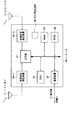
図1は、本発明を適用した情報処理システムの構成例を表している。この情報処理システムにおいては、家庭内にPHS(Personal Handy-Phone System)の親機43が設けられている。従って、PHSとしての機能を有する端末44は、家庭内のどの位置からも、親機43と無線で通信することができるようになされている。親機43はまた、電灯線12、またはバックボーン51を介して、ストレージ42を有するサーバ41との間でデータのやり取りを行う。
【0016】
電灯線12は、各部屋に配置されたセンサ40−1乃至40−7、エアコンディショナ3、冷蔵庫4、洗濯機5、湯沸かし器6、インターホン7、サーバ41、および親機43と接続されており、各種データを伝送する。
【0017】
バックボーン51は、TV受像機1、アンプ10、サーバ41、および親機43と接続されており、各種データを伝送する。
【0018】
オーディオ用バス52は、CDプレーヤ8、CDプレーヤ9、およびアンプ10と接続されており、各種データを伝送する。アンプ10は音声信号をスピーカ11−1,11−2に出力するようになされている。高速シリアルバス53は、同一部屋内のTV受像機1およびVCR2と接続されており、各種データを伝送する。
【0019】
サーバ41は、各種機器を制御することにより、端末44にサービスを提供するようになされている。サーバ41はまた、ストレージ42で各種データの検索を行う。サーバ41はまた、電話回線50を介して、外部との通信を行う。
【0020】
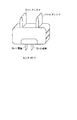
図2は、センサ40−1(センサ40−2乃至40−7も同様の形状とされている)の外形形状を表している。同図に示すように、このセンサ40−1は、電極70−1,70−2を有し、電極70−1,70−2を屋内コンセントに差し込むことにより、電灯線12から電力が供給されるとともに、電灯線12を介して親機43と信号を授受することができるようになされている。
【0021】
センサ40−1は、全体がテーブルタップの形状をしているため、屋内配線のコンセントを占領してしまうこともなく、設置場所も大きなスペースを必要としない。また、センサ40−1は、例えば、コンセントの場所から離れたところに設置する場合には壁から設置場所まで延長コードを用いればよいようになされている。
【0022】
そして、センサ40−1は、2個のアンテナ71−1,71−2を有し、端末44の電波をダイバーシチ受信することができるようになされている。PHSの電波を受信する場合、アンテナ面の偏波特性にばらつきが大きいことが知られている。そのため、その影響を最小限に抑えるため、アンテナ71−1,71−2は、比較的偏波に強い受信手段であるヘリカルアンテナとされている。
【0023】
次に、センサ40−1(センサ40−2乃至40−7も、センサ40−1と同様に構成されている)の内部の構成について、図3を参照して説明する。
【0024】
2本のアンテナ71−1,71−2は、それぞれ、端末44からの電波を受信し、受信信号を対応する受信感度測定装置90−1,90−2にそれぞれ出力するようになされている。受信感度測定装置90−1,90−2は受信感度を測定し、測定結果を比較器91に出力する。比較器91は、これらの信号のレベルの大きさを比較し、大きい値の方を選択する。CPU92は、ROM95に記憶されているプログラムに従って、各種の処理を実行する。RAM94は、CPU92が各種の処理を行うとき必要とされるプログラムやデータを記憶する。通信装置93は、電灯線12を介して、サーバ41との間で通信を行う。クロック発生回路96は、クロックを発生し、各部に出力している。
【0025】
次に、親機43、およびサーバ41の内部の構成について、図4を参照して説明する。
【0026】
親機43のPHS制御部110は、アンテナ111を介して、端末44との間で電波で無線通信を行うようになされている。PHS制御部110はまた、バックボーン51を介して、サーバ41の機器制御部113との間で、現在通信中の端末44に関する各種データやプログラムのやり取りを行う。メモリ118は、通話情報を適宜記憶する。
【0027】
サーバ41の通信回路112は、電灯線12やバックボーン51を介して、それらに接続された各種機器との間で通信を行う。通信回路112はまた、電話回線50を介して、外部と通信を行う。通信回路112はまた、通信を行うとき、通信プロトコルを適宜変換する。
【0028】
機器制御部113のユーザデータ管理部114は、端末44の情報をストレージ42に記憶させる。測定結果処理部115は、センサ40−1乃至40−7の出力する測定結果を処理する。個別サービス構築部116は、端末44から要求があったとき、所定の機器に命令を出力し、ユーザデータ管理部114が管理する情報に対応して、端末44に情報を供給する。タイミング制御部117は、センサ40−1乃至40−7に対しパルスを出力し、センサ40−1乃至40−4の測定のタイミングを制御する。
【0029】
次に、端末44の内部の構成について、図5を参照して説明する。
【0030】
通信部202は、アンテナ201を介して、親機43との間で無線通信を行うようになされている。スピーカ203は、通信部202から入力された信号を音声に変換して外部に出力する。マイクロホン204は、外部から入力された音声を信号に変換し、これを通信部202に出力する。
【0031】
CPU205は、ROM206に記憶されているプログラムに従って各種の処理を実行する。RAM207には、CPU205が各種の処理を実行する上において必要なデータ等が適宜記憶される。インタフェース208は、LCD209および入力部210とCPU205の間のインタフェース処理を実行する。LCD209は、所定の文字、図形、または画像を表示するようになされている。入力部210は、CPU205に所定の指令を入力するときユーザにより適宜操作される。
【0032】
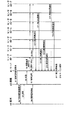
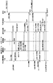
次に、図6の制御シーケンスを参照して、この情報処理システムの位置捕捉に関する動作を説明する。 最初にステップS1において、サーバ41のタイミング制御部117は、端末44に対し制御信号発信を要求するための信号を出力する。この要求信号はバックボーン51を介して親機43のPHS制御部110に伝送される。PHS制御部110は、このとき、ステップS2で、アンテナ111を介して無線で端末44に、制御信号発信を要求する。端末44の通信部202は、アンテナ201を介してこの信号を受信すると、受信信号をCPU205に出力する。CPU205はこのとき、ステップS3において、通信部202を制御し、アンテナ201を介して無線で応答信号を出力させる。
【0033】
親機43のPHS制御部110は、アンテナ111を介してこの応答信号を受信したとき、ステップS4で、その受信信号を、バックボーン51からサーバ41の通信回路112を介してタイミング制御部117に出力する。タイミング制御部117はこのとき、ステップS5において、各センサ40−1乃至40−7に対し、端末44の発する制御信号の受信感度測定命令を発信する。この命令は、通信回路112から電灯線12を介して各センサ40−1乃至40−7に供給される。この測定命令は、センサ40−1乃至40−7の通信装置93で受信される。CPU92は、通信装置93から、この測定命令の受信信号の供給を受けると、比較器91、および受信感度測定装置90−1,90−2を制御し、測定の準備を行わせる。
【0034】
端末44のCPU205は、ステップS6において、通信部202を制御し、アンテナ201を介して、無線で、センサ40−1乃至40−7および親機43に対して制御信号を発信させる。親機43のPHS制御部110は、アンテナ111を介してこの制御信号を受信し、ステップS7で、これをサーバ41のタイミング制御部117に出力する。この制御信号を受信したとき、サーバ41のタイミング制御部117は、ステップS8で、電灯線12を介して、図7に示すような測定パルスを各センサ40−1乃至40−7に出力する。この測定パルスは、端末44が制御信号を出力している期間において出力される。
【0035】
各センサ40−1乃至40−7のCPU92は、ステップS9で、測定パルス131−1乃至131−xが到来したタイミング毎に、比較器91および受信感度測定装置90−1,90−2に測定を実行させる。PHSの場合、バースト信号受信感度がタイミングによってばらつくことが知られている。そこで、この系においては、周期y毎に、x回の測定が行われるようになされている。
【0036】
各センサ40−1乃至40−7のCPU92は、x回の測定結果の平均値を演算し、演算結果を、ステップS10乃至S16で、通信装置93から電灯線12を介してサーバ41の通信回路112に出力する。図6の例の場合、センサ40−4,40−6,40−2,40−3,40−1,40−7,40−5の順番に測定結果が通知される。この順番は、サーバ41のタイミング制御部117により設定され、各センサ40−1乃至40−7のRAM94に予め記憶されている。サーバ41の測定結果処理部115は、ステップS17で、各センサ40−1乃至40−7の出力のうち、最大のものを検出する。
【0037】
サーバ41の個別サービス構築部116は、端末44が、最大感度を検出したセンサが存在する部屋に位置するものとして、ステップS18において、情報を提供する。例えば、端末44に対して、外部から電話がかかってきたとき、そのことを表すメッセージが、バックボーン51を介して、端末44と同室にある所定の機器であるTV受像機1に伝送され、表示される。
【0038】
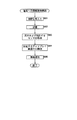
次に、図8のフローチャートを参照してセンサ40−1乃至40−7の動作をより詳細に説明する。
【0039】
最初に、ステップS31において、CPU92は、タイミング制御部117からの測定パルスに同期して測定処理を行うために、初期化を行い、ステップS32において、測定パルスを受信したか否かを判定する。測定パルスを受信したと判定した場合には、CPU92は、ステップS33において、比較器91および受信感度測定装置90−1,90−2に端末44からの電波を測定させる。
【0040】
CPU92は、ステップS33において、サーバ41のタイミング制御部117からの測定パルスに同期して測定を行った後、または、ステップS32で測定パルスを検出していないと判定されたとき、ステップS34に進み、測定を終了したか否か(測定をx回行ったか否か)の判定を行う。測定が終了していない(測定がx回行われていない)と判定された場合、ステップS32に戻り、同様の処理が繰り返し実行される。ステップS34で、測定が終了した(測定がx回行われた)と判定された場合、CPU92は、ステップS35に進み、測定を終了させる。なお、すべての測定結果は、RAM94上の所定エリアに個別に記憶される。
【0041】
このようにしてx回の測定が終了したとき、CPU92は、端末44からのバースト信号として供給される制御信号の受信感度のばらつきをふまえ、測定値から極端な値を外した上で、ステップS36で平均値を計算する。具体的には、すべての(x個の)測定値から最大値と最小値を除外し、その残りを加算した上で、(x−2)で除算する。CPU92は、ステップS37で、この計算結果を、測定値として、サーバ41の通信回路112に、通信装置93から通知させる。
【0042】
このとき、通信装置93は、測定結果と、センサ40−1乃至40−7の自らのID、および電波を発した端末44のIDを含む制御信号を出力する。なお、例えば、ROM95に、センサ40−1乃至40−7毎に異なる通信回路112内の固定アドレスを予め記憶させておき、そのアドレスに向けて信号を出力する場合には、そのアドレスからセンサ40−1乃至40−7を特定することができるので、センサ40−1乃至40−7毎のIDは不要となる。
【0043】
以上のようにして、センサ40−1乃至40−7により、端末44の電波の受信感度が測定され、サーバ41に通知される。
【0044】
次に、サーバ41で行われる動作(図6のステップS1,S5,S8,S17,S18に対応する動作)の詳細について、図9のフローチャートを参照してさらに説明する。
【0045】
最初にステップS50(図6のステップS1に対応する)において、サーバ41のタイミング制御部117は、バックボーン51を介して、親器43に、制御信号の発信を要求した後、ステップS51(図6のステップS5に対応する)において、通信回路112および電灯線25を介して、各センサ40−1乃至40−7の通信装置93に向けて測定命令を発信する。さらに、ステップS52(図6のステップS8に対応する)で、タイミング制御部117は、図7に示す測定パルスを出力する。その後、センサ40−1乃至40−7から回答があるまでステップS53で待機する。回答があると判定された場合にはステップS54に進み、通信回路112が、図8のステップS37(図6のステップS10乃至S16に対応する)で各センサ40−1乃至40−7から順次出力された測定結果を受信する。
【0046】
測定結果処理部115は、通信回路112から、この測定結果の供給を受けて、ステップS55でエラーを検出する。そして、ステップS56において、測定結果にエラーがあるか否かの判定を行う。エラーがあると判定された場合にはステップS57に進み、エラーの存在する情報を検出し、ステップS58でエラーを訂正する。その後はステップS55に戻り、エラーがないと判定されるまで、それ以降の処理を繰り返し実行する。
【0047】
例えば、エラー内容として、センサ40−1乃至40−7のうち、2つの異なるセンサが等しい測定値を通知していると判定されたとする。この場合、測定結果処理部115は、電波を発した端末44のIDをユーザデータ管理部114に転送し、その移動履歴を検索させる。そして、端末44が、位置変更できない程度に短い時間(例えば、5秒)だけ前の位置を検出する。例えば、過去の位置が、同一の測定値を出力した2つのセンサの位置の一方には近いのに対して、他方には遠いと判定されたとする。このとき測定結果処理部115は、過去の位置に近いと判定されたセンサの出力を残し、他方を破棄する。
【0048】
ステップS56においてエラーがないと判定された場合には、ステップS59に進み、測定結果処理部115は、その測定結果を記憶する。さらに、測定結果処理部115は、ステップS60において、このエラー訂正済の測定結果から、最大のものを1つ検出し、他のすべての測定結果をステップS61で破棄する。これにより、センサ40−1乃至40−7からの測定結果のうち、最大受信感度を測定したもののみが残されることになる。
【0049】
次のステップS62において、測定結果処理部115は、ステップS60において採用された、電波を発した端末44のID、およびセンサ40−1乃至40−7のうちの、最大受信感度を測定したセンサのIDを含む制御信号を出力する。この制御信号は、ユーザデータ管理部114に供給され、履歴としてストレージ42に記憶されるとともに、個別サービス構築部116に供給される。
【0050】
次に、サーバ41による、端末44への情報提供に関する動作(図6のステップS18に対応する)の詳細について、図10のフローチャートを参照して説明する。最初に、測定結果処理部115が、図9のステップS62で出力した制御信号が、ステップS81において、ユーザデータ管理部114に供給され、ステップS82でストレージ42に履歴として記憶される。また、この制御信号は個別サービス構築部116にも供給される。個別サービス構築部116は、ステップS83において、この信号から、端末44のID、および最大受信感度のセンサのIDを検出する。個別サービス構築部116は、ステップS84において、このIDのセンサと同一の部屋に設置された所定の機器(いまの場合はTV受像機41)のIDを検出する。
【0051】
個別サービス構築部116は、端末44が、最大感度を検出したセンサが存在する部屋に位置するものとして、ステップS85(図6のステップS18に対応する)において、その位置に対応する情報を提供する。
【0052】
例えば、端末44に対して、外部から電話がかかってきたとき、そのことを表すメッセージが、各部屋のうち、そのとき端末44が位置する部屋の、ステップS84でIDが検出された機器(例えば、TV受像機1)に、通信回路112からバックボーン51を介して伝送され、表示される。個別サービス構築部116はまた、PHS制御部110を制御し、アンテナ111を介して無線で、端末44を呼び出させる。端末44の通信部202は、アンテナ201を介してこの呼び出し信号を受け取ると、スピーカ203から出力する。また、このとき、CPU205は、インタフェース208を制御し、LCD209にメッセージを表示させる。
【0053】
端末44のユーザは、例えば、ヘッドフォンでオーディオ鑑賞中の場合、スピーカ203からの呼出音を認知することができないが、TV受像機1のメッセージから電話がかかってきたことを確認できる。
【0054】
次に、端末44の動作の詳細について、図11のフローチャートを参照して説明する。最初に、ステップS101において、CPU205は、サーバ41のタイミング制御部117からの制御信号発信要求の信号を、アンテナ201を介して通信部202が受信するまで待機する。発信要求を受信したと判定された場合には、CPU205は、ステップS102(図6のステップS3に対応する)で、通信部202を制御し、アンテナ201を介して無線で応答信号を出力させる。そして、CPU205は、ステップS103(図6のステップS6に対応する)において、通信部202を制御し、アンテナ201を介して、親機43に向けて制御信号を出力させる。
【0055】
CPU205は、ステップS104において、図10のステップS85で個別サービス構築部116が発する情報を、アンテナ201と通信部202を介して受信するまで待機する。情報を受信したと判定された場合には、ステップS105において、インタフェース208が、CPU205から情報の供給を受け、LCD209にそれを表示させる。
【0056】
このようにして、ユーザは、端末44を携帯することにより、家庭内の自分のいる任意の部屋において、その位置に応じた情報を享受することが可能になる。
【0057】
次に、この情報処理システムの、端末44の要求に対応して、サーバ41の制御で、親機43およびバックボーン51を介して行われるサービスに関する動作について、図12を参照して説明する。
【0058】
最初に、ステップS201において、ユーザは、端末44の入力部210から、サービスを受ける際の、具体的な要求情報を入力する。例えば、外部から電話があったとき、ユーザへの着信をTV受像機1を介して通知するよう、所定の操作により入力する。CPU205は、インタフェース208を介してこの要求情報を受け取ると、通信部202を制御して、ステップS202でアンテナ201より無線で要求に対応する信号を出力させる。親機43のPHS制御部110は、アンテナ111を介して要求情報を受信すると、ステップS203で、要求情報をサーバ41の通信回路112へバックボーン51を介して送出する。サーバ41の通信回路112は要求情報を受け取ると、ステップS204でユーザデータ管理部114へ送出する。ユーザデータ管理部114は、ステップS205で、通知された要求情報をストレージ42に記憶させる。
【0059】
ステップS206で外部からの着呼があり、これを感知した親機43のPHS制御部110は、ステップS207で、バックボーン51を介して、サーバ41の通信回路112に着信を通知する。通信回路112は、ステップS208において、個別サービス構築部116に着信を通知する。個別サービス構築部116は、ステップS209で、ユーザデータ管理部114にユーザ情報を問い合わせる。ユーザデータ管理部114は、ストレージ42からステップS205で記憶させた情報を検出し、ステップS210で問い合わせに応答する。
【0060】
例えば、対応するユーザが現在所定の部屋にいて(図6のステップS1乃至ステップS17における情報提供システムの動作により、この判定が可能になる)、着信がTV受像機1で通知されるよう既に設定を行っていることが共に通知される。
【0061】
そこで、サーバ41の個別サービス構築部116は、別室に設置されたTV受像機1に対し、画面に着信通知を表示するための命令情報を、まず通信回路112へ、ステップS211で送出する。通信回路112は、バックボーン51を介してステップS212(図6のステップS18に対応する)でTV受像機1に命令情報を送出する。TV受像機1は、命令情報を受信するとともに、ステップS213で画面に着信通知を表示する。
【0062】
サーバ41の個別サービス構築部116はまた、ユーザの端末44への入力補助のため、ユーザの手元の端末44へも、着信通知用のメッセージを、ステップS214で、通信回路112へ送出する。通信回路112は、受け取った着信メッセージを、ステップS215で、親機43のPHS制御部110へバックボーン51を介して送出する。親機43のPHS制御部110は、着信メッセージを受け取ると、ステップS216でアンテナ111を介して無線で送出することにより、端末44を呼び出す。
【0063】
端末44の通信部202は、アンテナ201を介してこの呼び出し信号を受け取ると、スピーカ203から出力する。また、このとき、CPU205は、ステップS217で、インタフェース208を制御し、LCD209にメッセージ(いまの場合は、着信通知、および応答のための入力ガイド)を表示させる。
【0064】
端末44のユーザは、例えば、ヘッドフォンでオーディオ鑑賞中の場合、スピーカ203からの呼出音を認知することができないが、TV受像機1のメッセージから電話がかかってきたことを確認できる。
【0065】
TV受像機1のディスプレイに気づいたユーザは、手元の端末44に表示されたガイドに従って、自己の意志、例えば留守番電話の応答指示を、ステップS218で、入力部210から要求情報として入力する。CPU205は、インタフェース208を介してこの要求情報を受け取り、通信部202を制御して、ステップS219でアンテナ201より無線で出力させる。親機43のPHS制御部110は、アンテナ111を介して要求情報を受信すると、ステップS220で、これを、サーバ41の通信回路112へバックボーン51を介して送出する。
【0066】
サーバ41の通信回路112は、受信した要求情報を、ステップS221で、個別サービス構築部116に送出する。個別サービス構築部116は、受け取った要求情報に基づく命令情報(いまの場合は、留守番電話応答の命令)を、ステップS222で通信回路112へ送出する。通信回路112は、受け取った命令情報を、ステップS223で、親機43のPHS制御部110へバックボーン51を介して出力する。
【0067】
親機43のPHS制御部110は命令情報を受け取ると、ステップS224で、メモリ118に予め記憶された留守番電話応答のメッセージを読み出し、これを用いて発信相手に応答する。サーバ41の個別サービス構築部116からは、着信表示の指示を出したTV受像機1の画面表示を終了させるため、ステップS225で、通信回路112に表示終了命令が送出される。通信回路112は、ステップS226で、バックボーン51を介してこの表示終了命令をTV受像機1に送出する。TV受像機1は、これを受信すると、ステップS227で表示を終了する。
【0068】
サーバ41の個別サービス構築部116はまた、端末44の表示を終了させるため、ステップS228で通信回路112に表示終了命令を送出する。通信回路112は、この表示終了命令を、ステップS229で親機43のPHS制御部110へバックボーン51を介して送出する。親機43のPHS制御部110は表示終了命令を受け取ると、ステップS230でアンテナ111を介して無線にて発信する。端末44のCPU205は、アンテナ201および通信部202を介して終了命令を受け取ると、ステップS231で、インタフェース208を制御してLCD209の表示を終了させる。
【0069】
以上のように、サーバ41が、親機43を介して無線で端末44に情報を提供するとともに、バックボーン51を介して、親機43、およびTV受像機1に命令を発することにより、ユーザにサービスが提供される。なお、この実施の形態は、バックボーン51を介して接続された他の機器(オーディオ用バス52や高速シリアルバス53を介して間接的に接続されたものも含む)にも応用が可能である。
【0070】
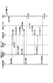
次に、本発明の情報処理システムを、入浴準備に適用した場合において、端末44の要求に対応して、サーバ41の制御で、親機43および電灯線12を介して行われるサービスに関する動作について、図13を参照して説明する。
【0071】
前提として、端末44が湯沸かし器6のある部屋へ入ると、図6のステップS7乃至S18の動作が行われ、端末44のLCD209に、ユーザが湯沸かし器6を操作するための入力ガイド情報が、サーバ41から親機43を介して提供され、表示されるものとする。
【0072】
ユーザは、ステップS301で、端末44の入力部210に、サービスを受ける際の具体的な要求情報を入力する。例えば、風呂の浴槽に供給するお湯を沸かす、湯沸かし器6の動作停止温度と、動作の開始を入力する。するよう予め設定しておく。CPU205は、インタフェース208を介してこの要求情報を受け取ると、通信部202を制御して、ステップS302でアンテナ201より無線で出力させる。
【0073】
親機43のPHS制御部110は、アンテナ111を介して要求情報を受信すると、ステップS303で、要求情報をサーバ41の通信回路112へ電灯線12を介して送出する。サーバ41の通信回路112は要求情報を受け取ると、ステップS304でユーザデータ管理部114へ転送する。ユーザデータ管理部114は、ステップS305で、通知された要求情報をストレージ42に記憶させる。
【0074】
また、サーバ41の通信回路112は、受信した要求情報を、ステップS306で、個別サービス構築部116に送出する。個別サービス構築部116は、要求情報を受け取ると、受け取った情報に基づく命令情報(いまの場合は、浴槽のお湯を沸かし、所定の温度に達した時点で停止する命令)を、ステップS307で通信回路112へ送出する。通信回路112は、受け取った命令情報を、ステップS308で、湯沸かし器6へ電灯線12を介して出力する。
【0075】
湯沸かし器6は命令情報を受け取ると、ステップS309で、命令された動作(浴槽のお湯を沸かすこと)を開始する。サーバ41の個別サービス構築部116はまた、端末44に確認のメッセージを表示させるため、ステップS310で通信回路112に、湯沸かし器6が作動中であることを示すメッセージを送出する。通信回路112は、この情報を、ステップS311で親機43のPHS制御部110へ電灯線12を介して送出する。親機43のPHS制御部110は情報を受け取ると、ステップS312でアンテナ111を介して無線にて発信する。端末44のCPU205は、アンテナ201および通信部202を介して情報を受け取ると、ステップS313で、インタフェース208を介してLCD209にメッセージを表示させる。
【0076】
お湯が、個別サービス構築部116からの命令により設定された温度に達すると、ステップS314で、湯沸かし器6が自動停止する。ステップS315で、湯沸かし器6から電灯線12を介して、サーバ41の通信回路112に、処理が完了したことが通知される。ステップS316で、通信回路112は、受け取った通知情報を個別サービス構築部116に送出する。
【0077】
サーバ41の個別サービス構築部116は、端末44に、湯沸かし器6の動作の終了を表示させるため、ステップS317で通信回路112に表示命令を送出する。通信回路112は、この表示命令を、ステップS318で親機43のPHS制御部110へ電灯線12を介して送出する。親機43のPHS制御部110は表示命令を受け取ると、ステップS319でアンテナ111を介して無線にて発信する。端末44のCPU205は、アンテナ201および通信部202を介して表示命令を受け取ると、ステップS320で、インタフェース208を介してLCD209に湯沸かし器6の動作の終了を表示させる。こうしてユーザは入浴準備が完了したことを知ることができる。
【0078】
以上のようにして、サーバ41が、親機43を介して無線で端末44に情報を提供するとともに、電灯線12を介して湯沸かし器6に命令するので、ユーザにサービスが提供される。なお、この実施の形態は、湯沸かし器6に限らず、電灯線12に接続された他の機器(オーディオ用バス52や高速シリアルバス53を介して間接的に接続されたものも含む)にも応用が可能である。
【0079】
なお、上記の実施の形態は、組み合わせて利用することも可能である。
【0080】
なお、上記したような処理を行うコンピュータプログラムをユーザに伝送する伝送媒体としては、磁気ディスク、CD-ROM、固体メモリなどの記録媒体の他、ネットワーク、衛星などの通信媒体を利用することができる。
【0081】
【発明の効果】
以上のように、請求項1に記載の情報処理システム、請求項3に記載の情報処理方法、および請求項4に記載の記録媒体によれば、3種類の伝送経路で機器を接続するようにしたので、ユーザは家庭内の任意の位置において、無線通信機能を有する1つの端末で各種機器を操作し、サービスを享受することが可能になる。
また、請求項5に記載の情報処理システムによれば、センサが、端末からの制御信号を無線通信により受信し、受信した制御信号の感度を測定し、測定された測定結果を、電灯線を介して情報提供装置に送信し、情報提供装置が、電灯線を介してセンサからの測定結果を受信し、測定結果から端末の位置を検出し、検出された端末の位置に基づき所定の機器を検出し、端末の位置に対応する情報を提供するための情報を提供するようにしたので、ユーザは家庭内の任意の位置において、無線通信機能を有する1つの端末で各種機器を操作し、サービスを享受することが可能になる。
さらに、請求項6に記載の情報提供装置、請求項10に記載の情報提供方法、および請求項11に記載の記録媒体によれば、センサにおいて、無線通信により端末からの制御信号の感度を測定した測定結果を、電灯線を介してセンサより受信し、測定結果から端末の位置を検出し、検出された端末の位置に基づき所定の機器を検出し、端末の位置に対応する情報を提供するようにしたので、ユーザは家庭内の任意の位置において、無線通信機能を有する1つの端末で各種機器を操作し、サービスを享受することが可能になる。
【図面の簡単な説明】
【図1】本発明を適用した情報処理システムの一実施の形態の構成を示すブロック図である。
【図2】図1のセンサ40−1の形状例を示す図である。
【図3】図1のセンサ40−1の内部の構成例を示すブロック図である。
【図4】図1の親機43およびサーバ41の内部の構成例を示すブロック図である。
【図5】図1の端末44の内部の構成例を示すブロック図である。
【図6】図1の情報処理システムの動作を説明する図である。
【図7】図1のセンサ40−1乃至40−7によるパルス測定のタイミングを示す図である。
【図8】図1のセンサ40−1乃至40−7の動作を説明するフローチャートである。
【図9】図1の端末44の位置検出の動作を説明するフローチャートである。
【図10】図1の端末44へ情報を提供する動作を説明するフローチャートである。
【図11】図1の端末44の動作を説明するフローチャートである。
【図12】図1の情報処理システムの他の動作を説明する図である。
【図13】図1の情報処理システムのさらに他の動作を説明する図である。
【図14】従来の遠隔操作システムの構成例を示すブロック図である。
【符号の説明】
1 TV受像機, 2 VCR, 3 エアコンディショナ, 4 冷蔵庫, 5洗濯機, 6 湯沸かし器, 7 インターホン, 8,9 CDプレーヤ, 10 アンプ, 11−1,11−2 スピーカ, 12 電灯線, 21乃至30 リモコン, 40−1乃至40−7 センサ, 41 サーバ, 42 ストレージ, 43 親機, 44 端末, 50 電話回線, 51 バックボーン, 52 オーディオ用バス, 53 高速シリアルバス, 70−1,70−2 電極, 71−1,71−2 アンテナ, 90−1,90−2 受信感度測定装置, 91 比較器, 92 CPU, 93 通信装置, 94 RAM, 95 ROM, 96 クロック発生回路, 110 PHS制御部, 111 アンテナ, 112 通信回路、113 機器制御部, 114 ユーザデータ管理部, 115 測定結果処理部, 116 個別サービス構築部, 117タイミング制御部, 118 メモリ, 131−1乃至131−x 測定パルス, 201 アンテナ, 202 通信部, 203 スピーカ, 204マイクロホン, 205 CPU, 206 ROM, 207 RAM, 208 インタフェース, 209 LCD, 210 入力部[0001]
BACKGROUND OF THE INVENTION
The present invention relates to an information processing system and method,Information providing apparatus and method,AndRecordRegarding the medium, in particular, indoors, a power line, a base unit having a wireless communication function, and a backbone that spans a room transmit various data under the control of a server, so that various devices connected thereto are wirelessly connected. Information processing system and method enabling operation with one terminal having a communication function,Information providing apparatus and method,AndRecordIt relates to the medium.
[0002]
[Prior art]
A method of using a remote commander (hereinafter referred to as a remote controller) as a means for remotely operating various devices in the home is known. A remote control system employing this method will be described with reference to FIG.
[0003]
A television (TV)
[0004]
The
[0005]
[Problems to be solved by the invention]
In the remote operation system shown in FIG. 14, each of the
[0006]
The present invention has been made in view of such a situation. For example, one terminal having a wireless communication function can operate various devices from an arbitrary indoor position.
[0007]
[Means for Solving the Problems]
The information processing system according to
[0008]
The information processing method according to
[0009]
Claim 4RecordThe medium isBetween the sensor and the first device via a power line to which a sensor that communicates wirelessly with the terminal device is connectedControl dataA first transmission control step for controlling the transmission of the first device to the terminal deviceWirelessThe second transmission control step for controlling the transmission of the first information and the result of communication between the terminal device and the sensor, the second device from the first device to the second device at a position close to the position of the terminal device. A third transmission control step for controlling transmission of the second information;TheIncludeComputer programRecordIt is characterized by doing.
The information processing system according to
The information providing device according to
The information providing method according to claim 10, wherein the sensor receives a measurement result obtained by measuring the sensitivity of the control signal from the terminal by wireless communication from the sensor via the power line, and the position of the terminal from the measurement result. And a information providing step of detecting a predetermined device based on the position of the terminal detected by the measurement result processing unit and providing information corresponding to the position of the terminal.
The recording medium according to claim 11 is a reception step of receiving a measurement result obtained by measuring the sensitivity of the control signal from the terminal by wireless communication from the sensor via a power line, and a position of the terminal from the measurement result. A computer program comprising: a detecting step for detecting; and an information providing step for detecting a predetermined device based on the position of the terminal detected by the measurement result processing unit and providing information corresponding to the position of the terminal; To do.
[0010]
The information processing system according to
In the information processing system according to
In the information providing apparatus according to
[0011]
DETAILED DESCRIPTION OF THE INVENTION
Embodiments of the present invention will be described below, but in order to clarify the correspondence between each means of the invention described in the claims and the following embodiments, in parentheses after each means, The features of the present invention will be described with the corresponding embodiment (however, an example) added. However, of course, this description does not mean that each means is limited to the description.
[0012]
That is, the information processing system according to
[0013]
The information processing system according to
The information processing system according to
The information providing apparatus according to claim 6 (for example, the
[0014]
Hereinafter, an information processing system to which the present invention is applied will be described. In this specification, the term “system” means an overall apparatus configured by a plurality of apparatuses, means, and the like.
[0015]
FIG. 1 shows a configuration example of an information processing system to which the present invention is applied. In this information processing system, a PHS (Personal Handy-Phone System)
[0016]
The power line 12 is connected to the sensors 40-1 to 40-7, the
[0017]
The backbone 51 is connected to the
[0018]
The audio bus 52 is connected to the
[0019]
The
[0020]
FIG. 2 shows the outer shape of the sensor 40-1 (the sensors 40-2 to 40-7 have the same shape). As shown in the figure, the sensor 40-1 has electrodes 70-1 and 70-2, and power is supplied from the power line 12 by inserting the electrodes 70-1 and 70-2 into an indoor outlet. In addition, a signal can be exchanged with the
[0021]
Since the entire sensor 40-1 has a table tap shape, it does not occupy an outlet for indoor wiring and does not require a large space for installation. For example, when the sensor 40-1 is installed at a location away from the location of the outlet, an extension cord may be used from the wall to the installation location.
[0022]
The sensor 40-1 has two antennas 71-1 and 71-2 so that the radio waves of the terminal 44 can be diversity-received. When receiving PHS radio waves, it is known that the polarization characteristics of the antenna surface vary greatly. Therefore, in order to minimize the influence, the antennas 71-1 and 71-2 are helical antennas which are receiving means relatively resistant to polarization.
[0023]
Next, an internal configuration of the sensor 40-1 (sensors 40-2 to 40-7 are configured in the same manner as the sensor 40-1) will be described with reference to FIG.
[0024]
The two antennas 71-1 and 71-2 receive radio waves from the terminal 44 and output received signals to the corresponding reception sensitivity measuring devices 90-1 and 90-2, respectively. The reception sensitivity measuring devices 90-1 and 90-2 measure the reception sensitivity and output the measurement result to the
[0025]
Next, the internal configuration of the
[0026]
The
[0027]
The
[0028]
The user
[0029]
Next, the internal configuration of the terminal 44 will be described with reference to FIG.
[0030]
The
[0031]
The
[0032]
Next, with reference to the control sequence shown in FIG. 6, the operation related to position acquisition of the information processing system will be described. First, in step S <b> 1, the
[0033]
When receiving the response signal via the antenna 111, the
[0034]
In step S <b> 6, the
[0035]
In step S9, the
[0036]
CPU92 of each sensor 40-1 thru | or 40-7 calculates the average value of x measurement result, and the communication result of the
[0037]
The individual
[0038]
Next, the operation of the sensors 40-1 to 40-7 will be described in more detail with reference to the flowchart of FIG.
[0039]
First, in step S31, the
[0040]
The
[0041]
When x measurements are completed in this way, the
[0042]
At this time, the
[0043]
As described above, the radio wave reception sensitivity of the terminal 44 is measured by the sensors 40-1 to 40-7 and notified to the
[0044]
Next, details of the operations performed in the server 41 (operations corresponding to steps S1, S5, S8, S17, and S18 in FIG. 6) will be further described with reference to the flowchart in FIG.
[0045]
First, in step S50 (corresponding to step S1 in FIG. 6), the
[0046]
The measurement
[0047]
For example, it is assumed that it is determined that two different sensors of the sensors 40-1 to 40-7 notify the same measurement value as the error content. In this case, the measurement
[0048]
If it is determined in step S56 that there is no error, the process proceeds to step S59, and the measurement
[0049]
In the next step S62, the measurement
[0050]
Next, details of an operation (corresponding to step S18 in FIG. 6) related to information provision by the
[0051]
The individual
[0052]
For example, when a call is received from the outside to the terminal 44, a message indicating that is sent to the device in which the ID is detected in step S84 of the room where the terminal 44 is located among the rooms (for example, , Transmitted to the TV receiver 1) from the
[0053]
For example, when listening to audio through headphones, the user of the terminal 44 cannot recognize the ringing sound from the
[0054]
Next, details of the operation of the terminal 44 will be described with reference to the flowchart of FIG. First, in step S <b> 101, the
[0055]
In step S <b> 104, the
[0056]
In this way, the user can enjoy the information corresponding to the position in any room where the user is in the home by carrying the terminal 44.
[0057]
Next, operations related to services performed through the
[0058]
First, in step S <b> 201, the user inputs specific request information for receiving a service from the input unit 210 of the terminal 44. For example, when there is a call from outside, an input to the user is made by a predetermined operation so as to notify the user via the
[0059]
In step S206, the
[0060]
For example, if the corresponding user is currently in a predetermined room (this determination can be made by the operation of the information providing system in steps S1 to S17 in FIG. 6), the incoming call is already set in the
[0061]
Therefore, the individual
[0062]
The individual
[0063]
When the
[0064]
For example, when listening to audio through headphones, the user of the terminal 44 cannot recognize the ringing sound from the
[0065]
The user who notices the display of the
[0066]
The
[0067]
When receiving the command information, the
[0068]
The individual
[0069]
As described above, the
[0070]
Next, in the case where the information processing system of the present invention is applied to bathing preparation, in response to a request from the terminal 44, operations related to services performed through the
[0071]
As a premise, when the terminal 44 enters the room where the
[0072]
In step S301, the user inputs specific request information for receiving a service to the input unit 210 of the terminal 44. For example, the operation stop temperature of the
[0073]
When receiving the request information via the antenna 111, the
[0074]
In addition, the
[0075]
Upon receiving the command information, the
[0076]
When the hot water reaches a temperature set by a command from the individual
[0077]
The individual
[0078]
As described above, the
[0079]
The above embodiments can be used in combination.
[0080]
As a transmission medium for transmitting a computer program for performing the above processing to a user, a communication medium such as a network or a satellite can be used in addition to a recording medium such as a magnetic disk, a CD-ROM, or a solid memory. .
[0081]
【The invention's effect】
As described above, the information processing system according to
According to the information processing system of
Furthermore, according to the information providing apparatus according to
[Brief description of the drawings]
FIG. 1 is a block diagram showing a configuration of an embodiment of an information processing system to which the present invention is applied.
FIG. 2 is a diagram illustrating a shape example of a sensor 40-1 in FIG.
3 is a block diagram showing an example of the internal configuration of a sensor 40-1 in FIG.
4 is a block diagram illustrating an internal configuration example of a
FIG. 5 is a block diagram showing an example of the internal configuration of a terminal 44 in FIG. 1;
6 is a diagram for explaining the operation of the information processing system of FIG. 1; FIG.
7 is a diagram showing pulse measurement timings by sensors 40-1 to 40-7 in FIG. 1; FIG.
FIG. 8 is a flowchart for explaining the operation of sensors 40-1 to 40-7 in FIG.
FIG. 9 is a flowchart for explaining the position detection operation of the terminal 44 in FIG. 1;
FIG. 10 is a flowchart illustrating an operation for providing information to the
FIG. 11 is a flowchart for explaining the operation of the terminal 44 in FIG. 1;
12 is a diagram for explaining another operation of the information processing system in FIG. 1. FIG.
13 is a diagram for explaining still another operation of the information processing system in FIG. 1. FIG.
FIG. 14 is a block diagram illustrating a configuration example of a conventional remote operation system.
[Explanation of symbols]
1 TV receiver, 2 VCR, 3 air conditioner, 4 refrigerator, 5 washing machine, 6 water heater, 7 intercom, 8, 9 CD player, 10 amplifier, 11-1, 11-2 speaker, 12 electric line, 21 thru 30 remote control, 40-1 to 40-7 sensor, 41 server, 42 storage, 43 master unit, 44 terminal, 50 telephone line, 51 backbone, 52 audio bus, 53 high-speed serial bus, 70-1, 70-2 electrode , 71-1, 71-2 antenna, 90-1, 90-2 reception sensitivity measuring device, 91 comparator, 92 CPU, 93 communication device, 94 RAM, 95 ROM, 96 clock generation circuit, 110 PHS control unit, 111 Antenna, 112 communication circuit, 113 device control unit, 114 user data management , 115 measurement result processing unit, 116 individual service construction unit, 117 timing control unit, 118 memory, 131-1 to 131 -x measurement pulse, 201 antenna, 202 communication unit, 203 speaker, 204 microphone, 205 CPU, 206 ROM, 207 RAM, 208 interface, 209 LCD, 210 input section
Claims (11)
前記端末装置と無線により通信する前記センサが接続されている電灯線を介して、前記センサと前記第1の機器との間で制御データを伝送する第1の伝送手段と、
前記第1の機器から前記端末装置に無線により第1の情報を伝送する第2の伝送手段と、
前記端末装置と前記センサとの通信の結果から、前記端末装置の位置に近い位置の前記第2の機器に、前記第1の機器から第2の情報を伝送する第3の伝送手段と、
前記第1の乃至前記第3の伝送手段を制御する制御手段と
を備えることを特徴とする情報処理システム。 In an information processing system including a terminal device, a sensor, a first device, and a second device ,
First transmission means for transmitting control data between the sensor and the first device via a power line to which the sensor that communicates wirelessly with the terminal device is connected ;
Second transmission means for transmitting first information wirelessly from the first device to the terminal device ;
From the result of communication between the terminal device and the sensor, third transmission means for transmitting second information from the first device to the second device at a position close to the position of the terminal device ;
An information processing system comprising: control means for controlling the first through third transmission means.
同一部屋内で、前記第2の機器に、制御データ、音声データ、コンピュータデータ、および映像データを伝送する第5の伝送手段と
をさらに備えることを特徴とする請求項1に記載の情報処理システム。Fourth transmission means for transmitting control data, audio data, and computer data to the second device in the same room;
The information processing system according to claim 1, further comprising: fifth transmission means for transmitting control data, audio data, computer data, and video data to the second device in the same room. .
前記端末装置と無線により通信する前記センサが接続されている電灯線を介して、前記センサと前記第1の機器との間での制御データの伝送を制御する第1の伝送制御ステップと、
前記第1の機器から前記端末装置への無線による第1の情報の伝送を制御する第2の伝送制御ステップと、
前記端末装置と前記センサとの通信の結果から、前記端末装置の位置に近い位置の前記第2の機器に対する、前記第1の機器からの第2の情報の伝送を制御する第3の伝送制御ステップと
を含むことを特徴とする情報処理方法。 In an information processing method of an information processing system including a terminal device, a sensor, a first device, and a second device ,
A first transmission control step for controlling transmission of control data between the sensor and the first device via a power line to which the sensor that communicates wirelessly with the terminal device is connected ;
A second transmission control step for controlling the transmission of the first information that by the radio from the first device to the terminal device,
Third transmission control for controlling transmission of second information from the first device to the second device at a position close to the position of the terminal device based on a result of communication between the terminal device and the sensor an information processing method which comprises the steps.
前記端末装置と無線により通信する前記センサが接続されている電灯線を介して、前記センサと前記第1の機器との間での制御データの伝送を制御する第1の伝送制御ステップと、
前記第1の機器から前記端末装置への無線による第1の情報の伝送を制御する第2の伝送制御ステップと、
前記端末装置と前記センサとの通信の結果から、前記端末装置の位置に近い位置の前記第2の機器に対する、前記第1の機器からの第2の情報の伝送を制御する第3の伝送制御ステップと
を含むことを特徴とするコンピュータが読み取り可能なプログラムが記録されている記録媒体。 A computer program used for an information processing system including a terminal device, a sensor, a first device, and a second device ,
A first transmission control step for controlling transmission of control data between the sensor and the first device via a power line to which the sensor that communicates wirelessly with the terminal device is connected ;
A second transmission control step for controlling the transmission of the first information that by the radio from the first device to the terminal device,
Third transmission control for controlling transmission of second information from the first device to the second device at a position close to the position of the terminal device based on a result of communication between the terminal device and the sensor Step and
A recording medium on which a computer-readable program is recorded.
前記センサは、The sensor is
前記端末からの制御信号を無線通信により受信するアンテナと、An antenna for receiving a control signal from the terminal by wireless communication;
前記アンテナで受信した前記制御信号の感度を測定する受信感度測定装置と、A receiving sensitivity measuring device for measuring the sensitivity of the control signal received by the antenna;
前記受信感度測定装置で測定された測定結果を、前記電灯線を介して前記情報提供装置に送信する通信装置とA communication device that transmits a measurement result measured by the reception sensitivity measuring device to the information providing device via the power line;
を備え、With
前記情報提供装置は、The information providing apparatus includes:
前記電灯線を介して前記センサからの前記測定結果を受信する通信回路と、A communication circuit for receiving the measurement result from the sensor via the power line;
前記測定結果から前記端末の位置を検出する測定結果処理部と、A measurement result processing unit for detecting the position of the terminal from the measurement result;
前記測定結果処理部により検出された前記端末の位置に基づき所定の機器を検出し、前記端末の位置に対応する情報を提供するための情報を提供する個別サービス構築部とAn individual service construction unit that detects information on a predetermined device based on the position of the terminal detected by the measurement result processing unit, and provides information for providing information corresponding to the position of the terminal;
を備えるWith
ことを特徴とする情報処理システム。An information processing system characterized by this.
前記センサにおいて、無線通信により前記端末からの制御信号の感度を測定した測定結果を、前記電灯線を介して前記センサより受信する通信回路と、In the sensor, a communication circuit that receives the measurement result of measuring the sensitivity of the control signal from the terminal by wireless communication from the sensor via the power line, and
前記測定結果から前記端末の位置を検出する測定結果処理部と、A measurement result processing unit for detecting the position of the terminal from the measurement result;
前記測定結果処理部により検出された前記端末の位置に基づき所定の機器を検出し、前記端末の位置に対応する情報を提供する個別サービス構築部とAn individual service construction unit for detecting a predetermined device based on the position of the terminal detected by the measurement result processing unit and providing information corresponding to the position of the terminal;
を備えることを特徴とする情報提供装置。An information providing apparatus comprising:
前記センサにより取得された前記端末のIDおよび前記センサのIDを、前記測定結果と共に前記電灯線を介して受信し、The ID of the terminal acquired by the sensor and the ID of the sensor are received together with the measurement result via the power line,
前記通信回路により受信された前記端末のIDおよび前記センサのIDを記憶するユーザデータ管理部を備え、A user data management unit for storing the ID of the terminal and the ID of the sensor received by the communication circuit;
前記個別サービス構築部は、The individual service construction unit
前記ユーザデータ管理部に記憶された前記端末のIDおよび前記センサのIDから前記所定の機器のIDを検出し、The ID of the predetermined device is detected from the ID of the terminal and the ID of the sensor stored in the user data management unit,
前記所定の機器に前記端末の位置に対応する情報を提供するProviding information corresponding to the position of the terminal to the predetermined device
ことを特徴とする請求項6に記載の情報提供装置。The information providing apparatus according to claim 6.
前記個別サービス構築部は、ユーザデータ管理部に記憶されている前記要求情報に基づき、前記所定の機器に前記情報を提供するための命令情報を、前記所定の機器に送信するThe individual service construction unit transmits, to the predetermined device, command information for providing the information to the predetermined device based on the request information stored in the user data management unit.
ことを特徴とする請求項7に記載の情報提供装置。The information providing apparatus according to claim 7.
前記個別サービス構築部は、無線通信機能を有する親機を介して、無線通信により前記端末に、前記端末の位置に対応する情報を提供するThe individual service construction unit provides information corresponding to the position of the terminal to the terminal by wireless communication via a base unit having a wireless communication function.
ことを特徴とする請求項6に記載の情報提供装置。The information providing apparatus according to claim 6.
前記センサにおいて、無線通信により前記端末からの制御信号の感度を測定した測定結果を、前記電灯線を介して前記センサより受信する受信ステップと、In the sensor, a reception step of receiving a measurement result obtained by measuring the sensitivity of the control signal from the terminal by wireless communication from the sensor via the power line;
前記測定結果から前記端末の位置を検出する検出ステップと、A detection step of detecting a position of the terminal from the measurement result;
前記測定結果処理部により検出された前記端末の位置に基づき所定の機器を検出し、前記端末の位置に対応する情報を提供する情報提供ステップとAn information providing step of detecting a predetermined device based on the position of the terminal detected by the measurement result processing unit and providing information corresponding to the position of the terminal;
を含むことを特徴とする情報提供方法。An information providing method comprising:
前記センサにおいて、無線通信により前記端末からの制御信号の感度を測定した測定結果を、前記電灯線を介して前記センサより受信する受信ステップと、In the sensor, a reception step of receiving a measurement result obtained by measuring the sensitivity of the control signal from the terminal by wireless communication from the sensor via the power line;
前記測定結果から前記端末の位置を検出する検出ステップと、A detection step of detecting a position of the terminal from the measurement result;
前記測定結果処理部により検出された前記端末の位置に基づき所定の機器を検出し、前記端末の位置に対応する情報を提供する情報提供ステップとAn information providing step of detecting a predetermined device based on the position of the terminal detected by the measurement result processing unit and providing information corresponding to the position of the terminal;
を含むことを特徴とするコンピュータが読み取り可能なプログラムが記録されている記A computer-readable program recorded on the computer. 録媒体。Recording media.
Priority Applications (1)
| Application Number | Priority Date | Filing Date | Title |
|---|---|---|---|
| JP33395197A JP3687828B2 (en) | 1997-12-04 | 1997-12-04 | Information processing system and method, information providing apparatus and method, and recording medium |
Applications Claiming Priority (1)
| Application Number | Priority Date | Filing Date | Title |
|---|---|---|---|
| JP33395197A JP3687828B2 (en) | 1997-12-04 | 1997-12-04 | Information processing system and method, information providing apparatus and method, and recording medium |
Publications (2)
| Publication Number | Publication Date |
|---|---|
| JPH11168471A JPH11168471A (en) | 1999-06-22 |
| JP3687828B2 true JP3687828B2 (en) | 2005-08-24 |
Family
ID=18271812
Family Applications (1)
| Application Number | Title | Priority Date | Filing Date |
|---|---|---|---|
| JP33395197A Expired - Fee Related JP3687828B2 (en) | 1997-12-04 | 1997-12-04 | Information processing system and method, information providing apparatus and method, and recording medium |
Country Status (1)
| Country | Link |
|---|---|
| JP (1) | JP3687828B2 (en) |
Families Citing this family (4)
| Publication number | Priority date | Publication date | Assignee | Title |
|---|---|---|---|---|
| JP4752143B2 (en) * | 2001-07-10 | 2011-08-17 | パナソニック株式会社 | Information processing device |
| CA2486671C (en) | 2002-05-31 | 2011-11-15 | Onkyo Corporation | Network type content reproducing system |
| JP4289025B2 (en) | 2003-05-28 | 2009-07-01 | ソニー株式会社 | Device control processing device, display processing device, method, and computer program |
| US7843333B2 (en) * | 2007-01-26 | 2010-11-30 | Sony Ericsson Mobile Communication Ab | System, methods, devices and computer program products for controlling electronic appliances within a local area |
-
1997
- 1997-12-04 JP JP33395197A patent/JP3687828B2/en not_active Expired - Fee Related
Also Published As
| Publication number | Publication date |
|---|---|
| JPH11168471A (en) | 1999-06-22 |
Similar Documents
| Publication | Publication Date | Title |
|---|---|---|
| CA2358226C (en) | Communication system, apparatus and methods employing multiple communication networks | |
| CN1992912B (en) | Method and device for adjusting image color in image projector | |
| KR100824038B1 (en) | A remote control apparatus and a receiver and an audio system | |
| JP2003526300A (en) | System and method for three-dimensional audio optimization | |
| JP3687828B2 (en) | Information processing system and method, information providing apparatus and method, and recording medium | |
| CN112235688A (en) | Method and device for adjusting sound field | |
| CN103209350B (en) | The acoustic signal notice of AD HOC communication pattern it is switched to from infrastructure communication pattern | |
| JP2001177890A (en) | Information reproduction system | |
| CN113393835A (en) | Voice interaction system, method and voice equipment | |
| US10542200B2 (en) | Surveillance camera system | |
| JP2002186063A (en) | Remote control system and mobile wireless terminal | |
| JP4342707B2 (en) | Electronic devices that can control other electronic devices | |
| CN114550393A (en) | Doorbell control method, electronic device and readable storage medium | |
| JP2003111159A (en) | Monitoring device | |
| JP3940942B2 (en) | Information processing apparatus and method, and recording medium | |
| JP6233664B2 (en) | Doorphone master unit and communication method | |
| JP2002186068A (en) | Remote controller | |
| CN105682010B (en) | Bluetooth connection control method, device and playback equipment in audio frequency broadcast system | |
| JPH0766767A (en) | Radio communication equipment | |
| JPH1127734A (en) | Going-out/staying home detector and man location system | |
| JPH05168087A (en) | Acoustic device and remote controller | |
| JP3692582B2 (en) | Voice eraser | |
| JP6583833B2 (en) | Server apparatus and communication method | |
| CN115002638A (en) | Method and device for detecting equipment assembly result based on microphone | |
| JP2001189947A (en) | Receiver, and transmitting and receiving method |
Legal Events
| Date | Code | Title | Description |
|---|---|---|---|
| A621 | Written request for application examination |
Free format text: JAPANESE INTERMEDIATE CODE: A621 Effective date: 20040428 |
|
| A977 | Report on retrieval |
Free format text: JAPANESE INTERMEDIATE CODE: A971007 Effective date: 20041207 |
|
| A131 | Notification of reasons for refusal |
Free format text: JAPANESE INTERMEDIATE CODE: A131 Effective date: 20041224 |
|
| A521 | Written amendment |
Free format text: JAPANESE INTERMEDIATE CODE: A523 Effective date: 20050222 |
|
| TRDD | Decision of grant or rejection written | ||
| A01 | Written decision to grant a patent or to grant a registration (utility model) |
Free format text: JAPANESE INTERMEDIATE CODE: A01 Effective date: 20050520 |
|
| A61 | First payment of annual fees (during grant procedure) |
Free format text: JAPANESE INTERMEDIATE CODE: A61 Effective date: 20050602 |
|
| FPAY | Renewal fee payment (event date is renewal date of database) |
Free format text: PAYMENT UNTIL: 20080617 Year of fee payment: 3 |
|
| FPAY | Renewal fee payment (event date is renewal date of database) |
Free format text: PAYMENT UNTIL: 20090617 Year of fee payment: 4 |
|
| FPAY | Renewal fee payment (event date is renewal date of database) |
Free format text: PAYMENT UNTIL: 20090617 Year of fee payment: 4 |
|
| FPAY | Renewal fee payment (event date is renewal date of database) |
Free format text: PAYMENT UNTIL: 20100617 Year of fee payment: 5 |
|
| FPAY | Renewal fee payment (event date is renewal date of database) |
Free format text: PAYMENT UNTIL: 20100617 Year of fee payment: 5 |
|
| FPAY | Renewal fee payment (event date is renewal date of database) |
Free format text: PAYMENT UNTIL: 20110617 Year of fee payment: 6 |
|
| FPAY | Renewal fee payment (event date is renewal date of database) |
Free format text: PAYMENT UNTIL: 20110617 Year of fee payment: 6 |
|
| FPAY | Renewal fee payment (event date is renewal date of database) |
Free format text: PAYMENT UNTIL: 20120617 Year of fee payment: 7 |
|
| FPAY | Renewal fee payment (event date is renewal date of database) |
Free format text: PAYMENT UNTIL: 20130617 Year of fee payment: 8 |
|
| LAPS | Cancellation because of no payment of annual fees |