JP3661604B2 - Microscopic observation apparatus and microscopic observation method - Google Patents
Microscopic observation apparatus and microscopic observation method Download PDFInfo
- Publication number
- JP3661604B2 JP3661604B2 JP2001106760A JP2001106760A JP3661604B2 JP 3661604 B2 JP3661604 B2 JP 3661604B2 JP 2001106760 A JP2001106760 A JP 2001106760A JP 2001106760 A JP2001106760 A JP 2001106760A JP 3661604 B2 JP3661604 B2 JP 3661604B2
- Authority
- JP
- Japan
- Prior art keywords
- observation
- imaging
- container
- well
- microscopic
- Prior art date
- Legal status (The legal status is an assumption and is not a legal conclusion. Google has not performed a legal analysis and makes no representation as to the accuracy of the status listed.)
- Expired - Fee Related
Links
Images


Classifications
-
- G—PHYSICS
- G02—OPTICS
- G02B—OPTICAL ELEMENTS, SYSTEMS OR APPARATUS
- G02B21/00—Microscopes
- G02B21/36—Microscopes arranged for photographic purposes or projection purposes or digital imaging or video purposes including associated control and data processing arrangements
- G02B21/365—Control or image processing arrangements for digital or video microscopes
Description
【0001】
【発明の属する技術分野】
本発明は、動植物細胞などの生体試料の顕微鏡画像を撮像する顕微観察装置および顕微観察方法に関するものである。
【0002】
【従来の技術】
生化学分野における各種の試験では、動植物の細胞や微生物などの生体試料を顕微鏡で観察するとともに生体試料の顕微鏡画像を取得する顕微観察作業が高頻度で行われる。観察対象の生体試料は通常マイクロプレートなどの容器に収容されており、従来はこのようなマイクロプレートに収容された生体試料の顕微鏡画像を撮像する際には、マイクロプレートを顕微鏡装置の試料台に装着して手動操作によって試料を移動させ、視野内に所望の観察対象部位を位置させた後に撮像を行う方法が一般的であった。
【0003】
【発明が解決しようとする課題】
しかしながら、一般に顕微観察作業は膨大な数量の試料を対象として行う必要があることから、上記従来方法による顕微観察作業には多大の手間と時間を要し、実験作業全体の効率の低下を招くとともに、実験担当者に過大の作業負荷を強いることとなっていた。
【0004】
そこで本発明は、生体試料の顕微鏡画像を効率よく取得することができる顕微観察装置および顕微観察方法を提供することを目的とする。
【0005】
【課題を解決するための手段】
請求項1記載の顕微観察装置は、容器の複数の試料収容部に収容された生体試料の顕微鏡画像を撮像する顕微観察装置であって、生体試料を収容する容器を保持する保持手段と、容器内の生体試料の顕微鏡画像を撮像する撮像手段と、この撮像手段に対して前記保持手段に保持された容器を相対的に移動させる移動手段と、前記容器に定義された基準点を原点とする複数の前記試料収容部の位置座標とこの位置座標を原点とする観察位置の相対位置座標に基づいて前記移動手段を制御することにより複数の前記試料収容部を前記撮像手段による撮像位置に位置決めする観察位置制御手段とを備えた。
【0006】
請求項2記載の顕微観察装置は、請求項1記載の顕微観察装置であって、前記観察位置制御手段が、前記容器に定義された基準点を原点とする複数の前記試料収容部の位置座標とこの位置座標を原点とする観察位置の相対位置座標より、前記基準点を原点とする観察位置の位置座標を求める観察位置座標算出部と、前記観察位置座標算出部で求めた観察位置の位置座標に基づいて前記移動手段を制御する機構制御部を備えている。
【0007】
請求項3記載の顕微観察装置は、請求項1記載の顕微観察装置であって、前記撮像手段の撮像位置の前記容器内における位置を示す画像を表示する表示手段と、表示された画像に基づいて観察位置を指示入力する入力手段を備えた。
【0008】
請求項4記載の顕微観察方法は、容器の複数の試料収容部に収容された生体試料の顕微鏡画像を撮像する顕微観察方法であって、前記容器を移動手段によって撮像手段に対して相対的に移動する保持手段に保持しておき、前記容器に定義された基準点を原点とする複数の前記試料収容部の位置座標とこの位置座標を原点とする観察位置の相対位置座標に基づいて前記移動手段を制御することにより複数の前記試料収容部を前記撮像手段による撮像位置に位置決めする。
【0009】
本発明によれば、容器内の生体試料の顕微鏡画像を撮像手段によって撮像するに際し、容器に定義された基準点を原点とする複数の試料収容部の位置座標とこの位置座標を原点とする観察位置の相対位置座標に基づいて、容器を保持して移動する移動手段を制御して複数の試料収容部を撮像手段による撮像位置に位置決めすることにより、生体試料の顕微鏡画像を効率よく取得することができる。
【0010】
【発明の実施の形態】
次に本発明の実施の形態を図面を参照して説明する。図1は本発明の一実施の形態の顕微観察装置の斜視図、図2は本発明の一実施の形態の顕微観察装置の構成を示すブロック図、図3は本発明の一実施の形態の顕微観察装置の位置決め処理の処理機能を示す機能ブロック図、図4(a)は本発明の一実施の形態の顕微観察装置のマイクロプレート情報の説明図、図4(b)は本発明の一実施の形態の顕微観察装置の観察位置情報の説明図、図5は本発明の一実施の形態の顕微観察装置の表示画面を示す図、図6は本発明の一実施の形態の顕微観察方法の基本動作プログラムの処理フロー図、図7は本発明の一実施の形態の顕微観察方法の自動観察プログラムの処理フロー図、図8は本発明の一実施の形態の顕微観察装置の試料テーブルの平面図である。
【0011】
まず図1、図2を参照して顕微観察装置について説明する。図1において顕微観察装置1は、架台2上に顕微観察部3および操作部4を並置して構成されている。顕微観察部3は、筐体5の内部に内蔵されたカメラ(後述)、生体試料の容器であるマイクロプレート7を保持する試料テーブル6を備えており、カメラによって光学系8を介してマイクロプレート7に収容された動植物細胞などの生体試料の顕微鏡画像を撮像する。また、顕微観察部3は接眼レンズ9を備えており、マイクロプレート7内の生体試料を接眼レンズ9を介して目視により観察できるようになっている。試料テーブル6は、生体試料の容器であるマイクロプレート7を保持する保持手段となっている。
【0012】
図8(a)は試料テーブル6の平面図である。6aは試料テーブル6に取り付けられた位置決め部であり、少なくともマイクロプレート7の直交する二つの側面に当接する。位置決め部6aとしては、本実施の形態のようなL字型のブロック以外に、複数のピンや試料テーブル6に形成した凹凸形状でもよい。6cは試料テーブル6に取り付けられたクランプ機構であり、弾性部材6dによって進退自在に支持された押し付け部材6bを備えている。6eは試料テーブル6の中央部に開口された開口部であり、この開口部6eを通じてカメラ13による生体試料の撮像が行われる。
【0013】
図8(b)はマイクロプレート7を保持した試料テーブル6の平面図を示す。マイクロプレート7を開口部6eの上方に配置し、クランプ機構6cの押し付け部材6bでマイクロプレート7の側面を位置決め部6aと挟み付けて保持する。位置決め部6aとクランプ機構6cによって保持されたマイクロプレート7の基準点Rは、位置決め部6aで規定される位置、すなわちテーブル移動機構11の座標系上に予め登録された位置に合致するように保持される。
【0014】
これにより、テーブル移動機構11に位置座標に基づく指令を出力することによりマイクロプレート7の所望の位置をカメラ13の撮像位置の上方に移動させることができる。位置決め部6aとクランプ機構6cは、マイクロプレート7を試料テーブル6の所定の位置(位置決め部6aで規定される位置、すなわちテーブル移動機構11の座標系上に登録された位置)に位置決めする位置決め手段を構成している。
【0015】
操作部4にはパーソナルコンピュータ10が配置されており、顕微観察部3によって撮像された画像を表示モニタ10a上で表示することができるようになっている。また入力画面や操作画面を表示モニタ10aに表示させることにより、キーボード10bやマウス10cによって各種データや操作コマンドの入力が行われる。
【0016】
次に図2を参照して顕微観察部3および制御系の構成を説明する。図2においてマイクロプレート7には生体試料を収容する試料収容部であるウェル7aが格子状に多数設けられている。マイクロプレート7は試料テーブル6に保持されており、試料テーブル6はテーブル移動機構11によってXY方向に水平移動する。試料テーブル6の下方には光学系8およびカメラ13が配設されており、カメラ13は試料テーブル6の上方に配置された照明部12によって照明されたウェル7a内の生体試料を撮像する。したがってカメラ13は容器内の生体試料の顕微鏡画像を撮像する撮像手段となっている。光学系8およびテーブル移動機構11は、機構制御部14によって制御される。テーブル移動機構11は、カメラ13に対して試料テーブル6に保持されたマイクロプレート7を相対的に移動させる移動手段となっている。
【0017】
処理部15はCPUであり、データ記憶部18に記憶されたデータに基づきプログラム格納部19に格納された各種プログラムを実行することにより、各種演算・処理を行う。第1画像記憶部16は、カメラ13によって撮像された画像データを記憶する。第2画像記憶部17は、第1画像記憶部16から読み出された画像データを画像処理した結果の処理画像を記憶する。
【0018】
データ記憶部18には、マイクロプレート情報18a、観察位置情報18bが記憶されている。マイクロプレート情報18aは、観察対象のマイクロプレート7におけるウェル7aの配列・位置に関する情報である。図4(a)に示すように、マイクロプレート7には、A〜Hの各列、1〜12の各行に格子状にウェル7aが配列されており、マイクロプレート情報18aには、ウェル7aの行数・列数、配列ピッチPx,Pyおよび1つのコーナ点に定義された基準点Rとこれに直近のウェル7aとの位置関係を特定するための位置座標(X0、Y0)(以下、基準ウェル位置座標と称する)が含まれる。
【0019】
1つのウェル7aの行番号・列番号を組み合わせたウェル番地が指定されることにより、このマイクロプレート情報18aとウェル番地に基づいて任意のウェル7aの位置座標を算出して特定することができる。すなわち任意のウェルのウェル番地と、基準ウェル位置座標(X0、Y0)と配列ピッチPx,Pyを用いて、任意のウェル7aの前記基準点Rを基準とする位置座標(図4(b)に示すウェル7aの中心位置座標(Xw、Yw)参照)が求められる。
【0020】
マイクロプレート7が載置される試料テーブル6上における基準点Rのテーブル移動機構11の座標系における位置座標は既知であることから、任意のウェル7aのウェル番地を指定することによりこのウェル7aのテーブル移動機構11の座標系における位置座標を計算し、この位置座標に基づいてテーブル移動機構11でマイクロプレート7を移動させて当該ウェル7aをカメラ13による撮像位置に位置決めすることができるようになっている。なおマイクロプレート情報18aとしては、ウェル番地によって該当するウェル7aの基準点Rからの位置座標が特定される情報であれば、上述した基準ウェル位置座標(X0、Y0)や、ウェル7aの行数、列数、配列ピッチPx,Pyは必ずしも必要ではない。
【0021】
観察位置情報18bは、1つのウェル7a内における観察位置、すなわち観察のためにカメラ13の撮像位置を相対移動させる目標位置を示す情報である。光学系8を介して顕微撮像を行う場合、カメラ13の撮像位置のサイズはウェル7aのサイズよりも小さく、1度の撮像でウェル7a内の全範囲をカバーすることができない。このため、図4(b)に示すように、同一のウェル7a内を複数回撮像して1つのウェル7aをカバーすることを目的として、撮像位置の移動目標となる観察位置27が複数箇所設定されている。ここでは、ウェル7aの中心部に設定される1つの観察位置27(観察位置番号1)の周囲に、60度等配位置に設定された6つの観察位置27(観察位置番号2〜7)が設定された例を示している。
【0022】
これらの個々の観察位置を示す座標は、当該ウェルに対する相対位置座標(ウェル7aの中心点(ウェル7aの中心位置座標(Xw、Yw))を原点とした位置座標。以下、「観察位置相対座標」という。)として設定されている。例えば、図4(b)に示すように、観察位置番号5の観察位置相対座標としてウェル7aの中心位置座標(Xw、Yw)に対する相対位置座標W5(x5、y5)が設定される。すなわち、任意の観察位置の観察位置番号が指定されることにより、観察位置情報18bに基づいて当該ウェルの中心点を基準とした当該観察位置の観察位置相対座標を特定することができる。
【0023】
したがって前述のウェル番地の指定と併せて観察位置番号を指定することにより、マイクロプレート情報18a、観察位置情報18bに基づいて、マイクロプレート7の任意のウェル7aの任意の観察位置27にカメラ13の撮像位置(撮像視野)を相対移動させて、所望の観察位置を撮像視野の中心とする生体試料の顕微鏡画像を撮像することができる。
【0024】
プログラム格納部19には、基本動作プログラム19a、位置決めプログラム19b,自動観察プログラム19c、画像処理プログラム19dが格納されている。基本動作プログラム19aは、顕微観察装置1による基本動作の処理プログラムであり、この基本動作によりマイクロプレート7内における観察位置を特定する移動指令が出力される。位置決めプログラム19bは、移動指令に基づいてマイクロプレート7の観察位置をカメラ9による撮像位置に位置決めする処理を行うプログラムである。これらのプログラムは処理部15によって実行される。
【0025】
図3を参照して位置決めプログラム19bによる位置決め処理について説明する。基本動作プログラム19aを実行することにより移動指令が出力されて、観察の対象となるウェル番地、もしくは観察位置を示す観察位置番号が指定される。移動指令としてウェル番地が入力されると、位置決めプログラム19bのウェル位置座標計算部23は、ウェル番地で指定されるウェルの位置座標を算出して、ウェル位置座標一時記憶部24に記憶する。移動指令として観察位置番号が入力されると、観察位置番号で指定された観察位置の観察位置相対座標を観察位置情報18bから読み取って、観察位置相対座標一時記憶部25に記憶する。
【0026】
観察位置座標算出部26は、ウェル位置座標一時記憶部24のウェル座標と、観察位置相対座標一時記憶部25の観察位置相対座標を読み取り、このウェル位置座標と観察位置相対座標とを加え合わせて、当該観察位置をカメラ13による撮像位置に移動させるための座標すなわち基準点Rを原点とする観察位置の位置座標(以下、観察位置座標と称する)を算出する。そしてこの観察位置座標が機構制御部14に出力され、機構制御部14がこの観察位置座標にしたがってテーブル移動機構11を制御することにより、試料テーブル6上のマイクロプレート7が移動して、所望の観察位置がカメラ13による撮像位置まで移動する。
【0027】
したがって、位置決めプログラム19bを処理部15によって実行することにより実現される観察位置座標算出機能および観察位置座標に基づいてテーブル移動機構11を制御する機構制御部14は、ウェルの位置座標と観察位置の観察位置相対座標に基づいてテーブル移動機構11を制御することにより、マイクロプレート7内の観察対象部位をカメラ13による撮像位置に位置決めする観察位置制御手段となっている。
【0028】
自動観察プログラム19cは、予め定められた観察順序に従って自動的にウェル内に設定された観察位置を定められた手順で観察するための処理を行うプログラムであり、後述するように操作画面上でボタン選択を行うことにより多数のウェル7aの各観察位置27をカメラ13の撮像位置に自動的に移動させて、連続して顕微観察を行えるようになっている。画像処理プログラム19dは、カメラ13によって撮像され第1画像記憶部16に記憶された画像データを対象とした画像処理を行うプログラムである。
【0029】
操作・入力部20は、パーソナルコンピュータ10のキーボード10bやマウス10cであり、操作画面上での入力操作を行う。表示部21はパーソナルコンピュータ10の表示モニタ10aであり、撮像された画像や操作画面の表示を行う。評価結果記憶部22は、画像処理によって得られた各種の数値データなどの評価結果を記憶する。
【0030】
次に図5を参照して、表示モニタ10aに表示される操作画面について説明する。図5において、画面30には観察位置を表示する観察位置表示ウインドウ31と撮像画像表示ウインドウ32が設定されている。観察位置表示ウインドウ31には、図4に示すマイクロプレート7を示すグラフィック画像70とウェル7aを示すグラフィック画像71と、ウェル7a内の観察位置27を示すグラフィック画像73が表示され、観察対象のウェル(ここではウェル番地D−5)に該当するグラフィック画像71’と、当該ウェル内での撮像対象となっている観察位置(ここでは観察位置番号7)に該当するグラフィック画像72’が、画面上で反転表示される。これにより、現在観察対象となっているウェル7a’および当該ウェル7a内での撮像位置の現在位置、すなわち観察対象となっている観察位置を画面30上で視覚的に知ることができる。したがって表示部21(表示モニタ10a)は、撮像位置に位置する観察位置(観察対象となっている観察位置)の位置をグラフィック画像を用いて視覚的に表示する表示手段となっている。
【0031】
また観察位置表示ウインドウ31は、移動指令を出力する操作パネルとしての機能も有しており、表示画面上での各グラフィック画像71,72は、移動指令を入力する操作ボタンとなっている。すなわちキーボード10bやマウス10cを操作して、画面上でポインタを所望のウェル7a、観察位置27に該当するグラフィック画像71,72に合わせてクリック入力することにより、ウェル番地や観察位置番号が位置決めプログラム19bに対して出力され、位置決めプログラム19bの処理によって、クリック入力により指定されたウェル7aの指定された観察位置27に、カメラ13の撮像位置を移動させることができるようになっている。したがって、操作・入力部20(キーボード10b、マウス10c)は、表示されたグラフィック画像上で撮像手段による観察位置を指示入力する入力手段となっている。
【0032】
撮像画像表示ウインドウ32には、現在撮像されている撮像画像34や、画像処理後の処理画像が表示される。画面30の右側には各種操作ボタンが表示されている。自動観察ボタン35を操作することにより、マイクロプレート7内の生体試料を自動観察する。すなわち、予め設定された順序に従って移動指令が位置決めプログラムに対して自動的に出力され、この移動指令に従ってカメラ13の撮像位置に観察位置が順次移動する。そして観察位置が移動する毎に、観察位置の生体試料の撮像および撮像により取得された画像データの画像処理が自動的に行われる。
【0033】
操作ボタン36〜40は移動指令入力ボタンであり、これらのボタンを操作することによりカメラ13の撮像位置に所定のウェル7a若しくは観察位置27が移動する。操作ボタン36,37はそれぞれウェル7aを対象とした移動指令を出力するための操作ボタンであり、これらのボタン操作により現在のウェル7aの次のウェル、前のウェルのウェル番地が位置決めプログラムに対して出力され、これと連動して観察位置表示ウインドウ31上でウェル7aの反転位置が1つ前進または後退する。
【0034】
また操作ボタン38,39はそれぞれ1つのウェル7a内での観察位置を対象とした移動指令であり、これらのボタン操作により現在の観察位置の次の観察位置や、前の観察位置の観察位置番号が位置決めプログラム19bに対して出力され、これと連動して観察位置表示ウインドウ31上で観察位置27の反転位置が1つ前進または後退する。
【0035】
操作ボタン40を操作することにより、マイクロプレート7の先頭のウェル7a、すなわち自動観察で1番目に観察される観察対象部位のウェル7aのウェル番地と観察位置27の観察位置番号が出力される。画像処理ボタン41を操作することにより、取得されて一旦記憶された画像を対象とした画像処理が実行される。そして終了ボタン42を操作することにより、顕微観察作業処理が終了する。このように、操作ボタン36〜41を操作することにより任意のウェルの任意の観察位置の観察を半自動にて行うことができる。
【0036】
この顕微観察装置は上記のように構成されており、以下各図を参照して動作について説明する。まず基本動作プログラムを実行することにより行われる処理について、図6のフロー図に沿って説明する。図6において、装置立ち上げにより、表示モニタ10a上に図5に示す操作画面が画面表示される(ST1)。そしてこの画面上で初期観察位置を示す初期値が入力される(ST2)。すなわち、位置決めプログラム19bに対してウェル番地A−1、観察位置番号1が入力され、ウェル番地A−1の観察位置番号1の観察位置が撮像位置に位置決めされる。これにより予め設定された順に各ウェル7aを対象として観察を自動的に行う自動観察の選択が可能となり、この状態で入力待機の状態となる(ST3)。
【0037】
そしてこの状態で何らかの入力が行われると、自動観察のボタン操作(図5の自動観察ボタン35)が行われたか否かが判断される(ST4)。ここで当該ボタン操作が行われたならば、自動観察が実行され(ST5)、その後再び(ST3)の入力待機状態に戻る。また自動観察が選択されない場合には、次に図5に示す操作ボタン36〜40,71,72のいずれかの操作が行われて移動指令が出力されたか否かが判断される(ST6)。ここで移動指令が出力されていないならば、画像処理ボタン41が操作されたか否かが判断され、当該ボタンが操作されていれば画像処理が実行され(ST8)、再び(ST3)の入力待機状態に戻る。(ST7)で画像処理ボタン41が押されていなければ、終了ボタン42が押されたものと判断して処理を終了する。
【0038】
(ST6)において移動指令が出力された場合には、位置決めプログラム19b(ST9〜ST13)が実行される。まず出力された移動指令はウェル番地か観察位置番号か判断される(ST9)。そしてウェル番地であればウェル番地に基づいて、図3に示すウェル位置座標計算部23によってウェル位置座標計算が行われる(ST10)。また観察位置番号であれば観察位置番号に基づいて読み取られた観察位置相対座標が観察位置相対座標一時記憶部25に記憶される(ST11)。そしてウェル位置座標と観察位置相対座標とに基づいて、観察位置座標算出部26により観察位置座標が算出され(ST12)、この観察位置座標が機構制御部14に出力されることにより、テーブル移動機構11が駆動される。これにより、指令されたウェルの指定された観察位置がカメラ13の撮像位置に移動し、この後再び(ST3)の入力待機状態に戻る。
【0039】
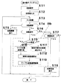
次に上記フロー図の(ST5)に示す自動観察を実行する際の処理フロー図について、図7を参照して説明する。ここでは、上記フロー図の(ST5)の先行ステップにて既に出力されているウェル番地のウェルを対象として、ウェル内の観察位置にカメラ13の撮像位置を順次移動させて、自動的に観察を行う処理を示している。
【0040】
まず観察位置番号(n)を1にセットして初期化し(ST21)、当該観察位置番号(n)への移動指令が出力される(ST22)。そして図6に示す(ST9)〜(ST13)と同様に位置決めプログラムが実行され(ST23)、次いで位置決めにより撮像位置に移動した観察位置27を撮像して得られた画像を対象とした画像処理が実行される(ST24)。画像処理結果は、評価結果記憶部22に記憶される。
【0041】
この後同一ウェル7a内に観察対象となる次の観察位置27があるか否かが判断される(ST25)。そして次の観察位置27ありの場合には観察位置番号のカウント数(n)を(n+1)に置き換え(ST26)、その後(ST22)に戻り、同様の観察処理を反復する。(ST25)にて次の観察位置27無しの場合には、観察対象となる次のウェル7aの有無を判断し(ST27)、次のウェル7aありの場合には当該次のウェル7aのウェル番地を移動指令として出力する(ST28)。その後(ST21)に戻り、同様の観察処理を反復する。そして(ST27)にて次のウェル7aがない場合には、全ての観察作業終了と判断して、自動観察を終了する。この自動観察においては、全てのウェル7aの全ての観察位置27が観察対象として設定されるとは限らず、マイクロプレート7の特定のウェル7aのみ、ウェル7a内の特定の観察位置27のみを観察対象として設定してもよい。
【0042】
すなわち上記生体試料の顕微鏡画像を撮像する顕微観察方法は、生体試料を収容するマイクロプレート7内における生体試料の観察位置を特定するための情報を、容器に定義された基準点を原点とした場合の試料収容部の位置座標とこの試料収容部の位置座標を原点とした場合の観察位置の相対位置座標とに分けて予め作成しておき、試料収容部の位置座標と観察位置の相対位置座標から観察位置の基準点を原点とする観察位置座標を求め、マイクロプレート7内の生体試料の顕微鏡画像をカメラ13によって撮像するに際し、このカメラ13に対してマイクロプレート7を相対的に移動させるテーブル移動機構11を求めた観察位置座標に基づいて制御することにより、マイクロプレート7の観察対象部位である特定のウェル7aの特定の観察位置27を、カメラ13による撮像位置に位置決めするものである。
【0043】
この顕微観察において、上記構成を用いることにより、マイクロプレート7の位置を手動操作によって微調整しながら撮像位置の位置決めを行っていた従来の方法と比較して、生体試料の顕微鏡画像を容易にかつ効率よく取得することができる。
【0044】
なお上記実施の形態では、生体試料を収容する容器として多数のウェル7aが格子状に形成されたマイクロプレート7を用いているが、本発明はこれに限定されるものではなく、これ以外の形態の容器であってもよい。例えば皿状の容器(ディッシュ)や、単なる板状のガラス基板などであっても、生体試料がこれら容器について予め設定された既知の位置に収納または載置され、これらの既知の位置に関するデータが試料収容部の位置情報として準備され、またこの試料収容部に対する相対座標で観察位置が設定されていれば、本発明の適用対象とすることができる。
【0045】
【発明の効果】
本発明によれば、容器内の生体試料の顕微鏡画像を撮像手段によって撮像するに際し、容器に定義された基準点を原点とする複数の試料収容部の位置座標とこの位置座標を原点とする観察位置の相対位置座標に基づいて、容器を保持して移動する移動手段を制御して複数の試料収容部を撮像手段による撮像位置に位置決めするようにしたので、生体試料の顕微鏡画像を効率よく取得することができる。
【図面の簡単な説明】
【図1】本発明の一実施の形態の顕微観察装置の斜視図
【図2】本発明の一実施の形態の顕微観察装置の構成を示すブロック図
【図3】本発明の一実施の形態の顕微観察装置の位置決め処理の処理機能を示す機能ブロック図
【図4】(a)本発明の一実施の形態の顕微観察装置のマイクロプレート情報の説明図
(b)本発明の一実施の形態の顕微観察装置の観察位置情報の説明図
【図5】本発明の一実施の形態の顕微観察装置の表示画面を示す図
【図6】本発明の一実施の形態の顕微観察方法の基本動作プログラムの処理フロー図
【図7】本発明の一実施の形態の顕微観察方法の自動観察プログラムの処理フロー図
【図8】本発明の一実施の形態の顕微観察装置の試料テーブルの平面図
【符号の説明】
3 顕微観察部
4 操作部
6 試料テーブル
7 マイクロプレート
7a ウェル
10a 表示モニタ
11 テーブル移動機構
14 機構制御部
15 処理部
18a マイクロプレート情報
18b 観察位置情報
19a 基本動作プログラム
19b 位置決めプログラム
19c 自動観察プログラム[0001]
BACKGROUND OF THE INVENTION
The present invention relates to a microscopic observation apparatus and a microscopic observation method for capturing a microscopic image of a biological sample such as an animal or plant cell.
[0002]
[Prior art]
In various tests in the biochemical field, a microscopic observation operation for observing a biological sample such as cells and microorganisms of animals and plants with a microscope and acquiring a microscopic image of the biological sample is frequently performed. A biological sample to be observed is usually stored in a container such as a microplate. Conventionally, when a microscopic image of a biological sample stored in such a microplate is taken, the microplate is placed on a sample stage of a microscope apparatus. A method of performing imaging after mounting and moving a sample by a manual operation and positioning a desired site to be observed in the field of view has been common.
[0003]
[Problems to be solved by the invention]
However, since the microscopic observation work generally needs to be performed on a large number of samples, the microscopic observation work by the above-described conventional method requires a lot of labor and time, leading to a decrease in the efficiency of the entire experimental work. , It was supposed to impose an excessive workload on the person in charge of the experiment.
[0004]
Accordingly, an object of the present invention is to provide a microscope observation apparatus and a microscope observation method that can efficiently acquire a microscope image of a biological sample.
[0005]
[Means for Solving the Problems]
The microscopic observation apparatus according to
[0006]
The microscopic observation apparatus according to
[0007]
The microscopic observation apparatus according to a third aspect is the microscopic observation apparatus according to the first aspect, wherein the display means displays an image indicating the position of the imaging position of the imaging means in the container, and the displayed image is based on the displayed image. Input means for instructing and inputting the observation position.
[0008]
The microscopic observation method according to
[0009]
According to the present invention, when a microscopic image of a biological sample in a container is picked up by an image pickup means, the position coordinates of a plurality of sample storage portions with the reference point defined in the container as the origin and the observation with the position coordinates as the origin Based on the relative position coordinates of the position, the moving means for holding and moving the container is controlled to position a plurality of sample storage portions at the imaging positions by the imaging means, thereby efficiently acquiring a microscopic image of the biological sample. Can do.
[0010]
DETAILED DESCRIPTION OF THE INVENTION
Next, embodiments of the present invention will be described with reference to the drawings. FIG. 1 is a perspective view of a microscopic observation apparatus according to an embodiment of the present invention, FIG. 2 is a block diagram showing the configuration of the microscopic observation apparatus according to an embodiment of the present invention, and FIG. 3 is an embodiment of the present invention. 4 is a functional block diagram showing the processing function of the positioning process of the microscopic observation apparatus, FIG. 4A is an explanatory diagram of microplate information of the microscopic observation apparatus of one embodiment of the present invention, and FIG. FIG. 5 is a diagram illustrating a display screen of the microscope observation apparatus according to the embodiment of the present invention, and FIG. 6 is a microscope observation method according to the embodiment of the present invention. FIG. 7 is a process flow diagram of the automatic observation program of the microscopic observation method according to the embodiment of the present invention, and FIG. 8 is a diagram of the sample table of the microscopic observation apparatus according to the embodiment of the present invention. It is a top view.
[0011]
First, the microscopic observation apparatus will be described with reference to FIGS. In FIG. 1, a
[0012]
FIG. 8A is a plan view of the sample table 6.
[0013]
FIG. 8B shows a plan view of the sample table 6 holding the
[0014]
Thereby, the desired position of the
[0015]
A
[0016]
Next, the configuration of the
[0017]
The
[0018]
The
[0019]
By specifying a well address that is a combination of the row number and column number of one
[0020]
Since the position coordinates in the coordinate system of the
[0021]
The
[0022]
The coordinates indicating these individual observation positions are relative position coordinates with respect to the well (position coordinates with the center point of the
[0023]
Therefore, by designating the observation position number together with the designation of the well address described above, the
[0024]
The
[0025]
The positioning process by the
[0026]
The observation position coordinate
[0027]
Therefore, the observation position coordinate calculation function realized by executing the
[0028]
The
[0029]
The operation /
[0030]
Next, an operation screen displayed on the
[0031]
The observation
[0032]
The captured
[0033]
The
[0034]
The
[0035]
By operating the
[0036]
This microscope observation apparatus is configured as described above, and the operation will be described below with reference to the drawings. First, processing performed by executing the basic operation program will be described with reference to the flowchart of FIG. In FIG. 6, when the apparatus is started, the operation screen shown in FIG. 5 is displayed on the
[0037]
If any input is performed in this state, it is determined whether or not an automatic observation button operation (
[0038]
When a movement command is output in (ST6),
[0039]
Next, a processing flow chart when executing the automatic observation shown in (ST5) of the above flow chart will be described with reference to FIG. Here, for the well at the well address already output in the preceding step (ST5) of the above flow diagram, the imaging position of the
[0040]
First, the observation position number (n) is set to 1 and initialized (ST21), and a movement command to the observation position number (n) is output (ST22). Then, a positioning program is executed in the same manner as (ST9) to (ST13) shown in FIG. 6 (ST23), and then image processing for an image obtained by imaging the
[0041]
Thereafter, it is determined whether or not there is a
[0042]
That is, in the microscopic observation method for capturing a microscopic image of the biological sample, the information for specifying the observation position of the biological sample in the
[0043]
In this microscopic observation, by using the above configuration, a microscope image of a biological sample can be easily and easily compared with the conventional method in which the position of the
[0044]
In the above embodiment, the
[0045]
【The invention's effect】
According to the present invention, when a microscopic image of a biological sample in a container is picked up by an image pickup means, the position coordinates of a plurality of sample storage portions with the reference point defined in the container as the origin and the observation with the position coordinates as the origin Based on the relative position coordinates, the moving means that holds and moves the container is controlled so that the plurality of sample storage portions are positioned at the imaging position by the imaging means, so that a microscopic image of the biological sample can be efficiently acquired. can do.
[Brief description of the drawings]
FIG. 1 is a perspective view of a microscopic observation apparatus according to an embodiment of the present invention.
FIG. 2 is a block diagram showing a configuration of a microscopic observation apparatus according to an embodiment of the present invention.
FIG. 3 is a functional block diagram showing processing functions of positioning processing of the microscope observation apparatus according to the embodiment of the present invention.
FIG. 4A is an explanatory diagram of microplate information of a microscopic observation apparatus according to an embodiment of the present invention.
(B) Explanatory drawing of the observation position information of the microscope observation apparatus of one embodiment of this invention
FIG. 5 is a diagram showing a display screen of the microscopic observation apparatus according to the embodiment of the present invention.
FIG. 6 is a processing flowchart of a basic operation program of the microscopic observation method according to the embodiment of the present invention.
FIG. 7 is a process flow diagram of an automatic observation program for a microscopic observation method according to an embodiment of the present invention.
FIG. 8 is a plan view of the sample table of the microscope observation apparatus according to the embodiment of the present invention.
[Explanation of symbols]
3 Microscopic observation part
4 Operation part
6 Sample table
7 Microplate
7a well
10a Display monitor
11 Table moving mechanism
14 Mechanism controller
15 Processing unit
18a microplate information
18b Observation position information
19a Basic operation program
19b Positioning program
19c Automatic observation program
Claims (4)
Priority Applications (2)
| Application Number | Priority Date | Filing Date | Title |
|---|---|---|---|
| JP2001106760A JP3661604B2 (en) | 2001-04-05 | 2001-04-05 | Microscopic observation apparatus and microscopic observation method |
| US10/114,328 US20020154216A1 (en) | 2001-04-05 | 2002-04-03 | Method and apparatus for microscopic observation |
Applications Claiming Priority (1)
| Application Number | Priority Date | Filing Date | Title |
|---|---|---|---|
| JP2001106760A JP3661604B2 (en) | 2001-04-05 | 2001-04-05 | Microscopic observation apparatus and microscopic observation method |
Publications (2)
| Publication Number | Publication Date |
|---|---|
| JP2002303801A JP2002303801A (en) | 2002-10-18 |
| JP3661604B2 true JP3661604B2 (en) | 2005-06-15 |
Family
ID=18959210
Family Applications (1)
| Application Number | Title | Priority Date | Filing Date |
|---|---|---|---|
| JP2001106760A Expired - Fee Related JP3661604B2 (en) | 2001-04-05 | 2001-04-05 | Microscopic observation apparatus and microscopic observation method |
Country Status (2)
| Country | Link |
|---|---|
| US (1) | US20020154216A1 (en) |
| JP (1) | JP3661604B2 (en) |
Families Citing this family (13)
| Publication number | Priority date | Publication date | Assignee | Title |
|---|---|---|---|---|
| DE102005025017A1 (en) * | 2005-05-30 | 2006-12-07 | Basf Ag | Use of amphiphilic block copolymers for the preparation of polymer blends |
| JP5034328B2 (en) * | 2006-06-08 | 2012-09-26 | 株式会社ニコン | Observation device and observation program |
| JP5208650B2 (en) * | 2008-09-29 | 2013-06-12 | オリンパス株式会社 | Microscope system |
| DK200801722A (en) | 2008-12-05 | 2010-06-06 | Unisensor As | Optical sectioning of a sample and detection of particles in a sample |
| RU2548597C2 (en) | 2009-12-04 | 2015-04-20 | Юнисенсор А/С | System and method for time-related microscopy of biological organisms |
| US8341193B2 (en) * | 2010-01-12 | 2012-12-25 | Microsoft Corporation | Data versioning through data transformations |
| JP5479950B2 (en) * | 2010-03-03 | 2014-04-23 | オリンパス株式会社 | Microscope device and observation position reproduction method |
| JP5769116B2 (en) | 2010-03-04 | 2015-08-26 | コーニンクレッカ フィリップス エヌ ヴェ | Flexible sample container |
| JP5585215B2 (en) * | 2010-05-31 | 2014-09-10 | 株式会社ニコン | Microscope control apparatus, imaging system, and program |
| JP5558601B2 (en) * | 2013-02-20 | 2014-07-23 | オリンパス株式会社 | Microscope system |
| JP6395251B2 (en) * | 2014-05-30 | 2018-09-26 | 国立研究開発法人理化学研究所 | Optical microscope system and screening device |
| JP6347287B2 (en) * | 2016-12-05 | 2018-06-27 | ソニー株式会社 | Measuring apparatus, program, and measuring method |
| JP6707207B2 (en) * | 2017-09-27 | 2020-06-10 | 富士フイルム株式会社 | Observation device, observation method, and observation program |
Family Cites Families (20)
| Publication number | Priority date | Publication date | Assignee | Title |
|---|---|---|---|---|
| US3792264A (en) * | 1972-12-27 | 1974-02-12 | T Lacey | Photographic apparatus |
| US4628026A (en) * | 1983-11-15 | 1986-12-09 | Dietlind Gardell | Method and apparatus for automated double fluorochromization analysis in lymphocytotoxicity testing |
| JPH0628144B2 (en) * | 1986-10-08 | 1994-04-13 | 株式会社日立製作所 | Device for driving sample stage such as microscope |
| US5216596A (en) * | 1987-04-30 | 1993-06-01 | Corabi International Telemetrics, Inc. | Telepathology diagnostic network |
| US6051834A (en) * | 1991-05-15 | 2000-04-18 | Hitachi, Ltd. | Electron microscope |
| JP3129015B2 (en) * | 1993-02-16 | 2001-01-29 | 株式会社日立製作所 | Inspection method and apparatus for dyed particles |
| US5587833A (en) * | 1993-07-09 | 1996-12-24 | Compucyte Corporation | Computerized microscope specimen encoder |
| US5976824A (en) * | 1993-11-24 | 1999-11-02 | Abbott Laboratories | Method and apparatus for collecting a cell sample from a liquid specimen |
| US5581487A (en) * | 1994-02-23 | 1996-12-03 | Science Applications International Corporation | Method and apparatus for microscopic screening of cytological samples |
| US6172363B1 (en) * | 1996-03-05 | 2001-01-09 | Hitachi, Ltd. | Method and apparatus for inspecting integrated circuit pattern |
| US6259960B1 (en) * | 1996-11-01 | 2001-07-10 | Joel Ltd. | Part-inspecting system |
| US6122562A (en) * | 1997-05-05 | 2000-09-19 | Applied Materials, Inc. | Method and apparatus for selectively marking a semiconductor wafer |
| JP3739550B2 (en) * | 1997-10-29 | 2006-01-25 | 大日本スクリーン製造株式会社 | Method for determining wafer measurement position |
| US6518570B1 (en) * | 1998-04-03 | 2003-02-11 | Brookhaven Science Associates | Sensing mode atomic force microscope |
| JP3540174B2 (en) * | 1998-10-12 | 2004-07-07 | ウシオ電機株式会社 | Proximity exposure method for irradiating light obliquely |
| US6738505B1 (en) * | 1999-05-04 | 2004-05-18 | Speedline Technologies, Inc. | Method and apparatus for detecting solder paste deposits on substrates |
| US6535626B1 (en) * | 2000-01-14 | 2003-03-18 | Accumed International, Inc. | Inspection system with specimen preview |
| JP4015352B2 (en) * | 2000-02-22 | 2007-11-28 | 株式会社日立製作所 | Inspection method using charged particle beam |
| US6958769B2 (en) * | 2000-10-20 | 2005-10-25 | S&S X-Ray Products, Inc. | High resolution sheet metal scanner with independent tracking light source |
| JP2004512845A (en) * | 2000-10-24 | 2004-04-30 | オンコシス リミテッド ライアビリティ カンパニー | Methods and devices for selectively targeting cells in a three-dimensional specimen |
-
2001
- 2001-04-05 JP JP2001106760A patent/JP3661604B2/en not_active Expired - Fee Related
-
2002
- 2002-04-03 US US10/114,328 patent/US20020154216A1/en not_active Abandoned
Also Published As
| Publication number | Publication date |
|---|---|
| JP2002303801A (en) | 2002-10-18 |
| US20020154216A1 (en) | 2002-10-24 |
Similar Documents
| Publication | Publication Date | Title |
|---|---|---|
| JP3661604B2 (en) | Microscopic observation apparatus and microscopic observation method | |
| US7630628B2 (en) | Microscope system and microscope observation method | |
| EP2541300A1 (en) | Manipulator system and method for manipulating microscopic object to be manipulated | |
| JP3962104B2 (en) | Method for operating an infrared microscope and apparatus for acquiring infrared data | |
| JPH07289757A (en) | Computerized sewing machine | |
| US20060176367A1 (en) | Photo-micrographing device and its control method | |
| JP2011186305A (en) | Virtual-slide creating device | |
| CN110712194B (en) | Object inspection device, object inspection system, and method of adjusting inspection position | |
| EP2232320B1 (en) | System for controlably scanning a cytological specimen | |
| US20080079932A1 (en) | Visual inspection apparatus and visual inspection method | |
| JP7459331B2 (en) | Microscope system control method, microscope system | |
| US7954069B2 (en) | Microscopic-measurement apparatus | |
| JP5677770B2 (en) | Medical diagnosis support device, virtual microscope system, and specimen support member | |
| JP2009078345A (en) | Manipulator, manipulator system, and image display device for manipulator, and manipulation system | |
| JPH05258705A (en) | Microscope image display device | |
| Mattos et al. | Semi-automated blastocyst microinjection | |
| JP2009211027A (en) | Manipulator system and method for operating minute object to be operated | |
| JP5091460B2 (en) | Inspection and measurement equipment | |
| CN106525624A (en) | Hardness test apparatus and hardness testing method | |
| JP2007033372A (en) | Visual inspection device | |
| JP2009042462A (en) | Microscope apparatus, observation method, and observed image processing method | |
| JP5257276B2 (en) | Manipulation system drive method | |
| JP4136099B2 (en) | Board inspection equipment | |
| JP2001211875A (en) | Device for collecting fine bodies and method of collecting the same | |
| JP2003030638A (en) | Image display device, image display method and control program therefor |
Legal Events
| Date | Code | Title | Description |
|---|---|---|---|
| A977 | Report on retrieval |
Free format text: JAPANESE INTERMEDIATE CODE: A971007 Effective date: 20050225 |
|
| TRDD | Decision of grant or rejection written | ||
| A01 | Written decision to grant a patent or to grant a registration (utility model) |
Free format text: JAPANESE INTERMEDIATE CODE: A01 Effective date: 20050301 |
|
| A61 | First payment of annual fees (during grant procedure) |
Free format text: JAPANESE INTERMEDIATE CODE: A61 Effective date: 20050314 |
|
| FPAY | Renewal fee payment (event date is renewal date of database) |
Free format text: PAYMENT UNTIL: 20080401 Year of fee payment: 3 |
|
| FPAY | Renewal fee payment (event date is renewal date of database) |
Free format text: PAYMENT UNTIL: 20090401 Year of fee payment: 4 |
|
| FPAY | Renewal fee payment (event date is renewal date of database) |
Free format text: PAYMENT UNTIL: 20100401 Year of fee payment: 5 |
|
| LAPS | Cancellation because of no payment of annual fees |