JP3651753B2 - Oil removal system and equipment - Google Patents
Oil removal system and equipment Download PDFInfo
- Publication number
- JP3651753B2 JP3651753B2 JP27060898A JP27060898A JP3651753B2 JP 3651753 B2 JP3651753 B2 JP 3651753B2 JP 27060898 A JP27060898 A JP 27060898A JP 27060898 A JP27060898 A JP 27060898A JP 3651753 B2 JP3651753 B2 JP 3651753B2
- Authority
- JP
- Japan
- Prior art keywords
- oil
- fat
- tank
- separation tank
- grease
- Prior art date
- Legal status (The legal status is an assumption and is not a legal conclusion. Google has not performed a legal analysis and makes no representation as to the accuracy of the status listed.)
- Expired - Lifetime
Links
- 239000003921 oil Substances 0.000 claims description 189
- 239000003925 fat Substances 0.000 claims description 129
- 238000000926 separation method Methods 0.000 claims description 66
- 239000004519 grease Substances 0.000 claims description 63
- 238000005406 washing Methods 0.000 claims description 37
- 238000004140 cleaning Methods 0.000 claims description 35
- XLYOFNOQVPJJNP-UHFFFAOYSA-N water Substances O XLYOFNOQVPJJNP-UHFFFAOYSA-N 0.000 claims description 33
- 239000007788 liquid Substances 0.000 claims description 13
- 239000002351 wastewater Substances 0.000 claims description 11
- 238000001179 sorption measurement Methods 0.000 claims description 9
- 235000014347 soups Nutrition 0.000 claims description 7
- 238000004851 dishwashing Methods 0.000 claims description 3
- 238000005086 pumping Methods 0.000 claims description 3
- 235000015067 sauces Nutrition 0.000 claims description 3
- 235000019198 oils Nutrition 0.000 description 169
- 238000010586 diagram Methods 0.000 description 11
- 238000010411 cooking Methods 0.000 description 5
- 239000010775 animal oil Substances 0.000 description 4
- 238000011084 recovery Methods 0.000 description 4
- 235000015112 vegetable and seed oil Nutrition 0.000 description 4
- 239000008158 vegetable oil Substances 0.000 description 4
- 239000003599 detergent Substances 0.000 description 3
- 235000021186 dishes Nutrition 0.000 description 3
- 230000000694 effects Effects 0.000 description 3
- 239000012535 impurity Substances 0.000 description 3
- 235000021190 leftovers Nutrition 0.000 description 3
- 235000014593 oils and fats Nutrition 0.000 description 3
- 241000209094 Oryza Species 0.000 description 2
- 235000007164 Oryza sativa Nutrition 0.000 description 2
- 238000011109 contamination Methods 0.000 description 2
- 230000005484 gravity Effects 0.000 description 2
- 238000010438 heat treatment Methods 0.000 description 2
- 230000002209 hydrophobic effect Effects 0.000 description 2
- 230000003993 interaction Effects 0.000 description 2
- 238000004064 recycling Methods 0.000 description 2
- 235000009566 rice Nutrition 0.000 description 2
- 238000002791 soaking Methods 0.000 description 2
- 239000002689 soil Substances 0.000 description 2
- 239000007787 solid Substances 0.000 description 2
- 238000007711 solidification Methods 0.000 description 2
- 230000008023 solidification Effects 0.000 description 2
- 238000010521 absorption reaction Methods 0.000 description 1
- 230000015556 catabolic process Effects 0.000 description 1
- 238000006731 degradation reaction Methods 0.000 description 1
- 235000015071 dressings Nutrition 0.000 description 1
- 239000010808 liquid waste Substances 0.000 description 1
- 230000007774 longterm Effects 0.000 description 1
- 239000002184 metal Substances 0.000 description 1
- 238000000034 method Methods 0.000 description 1
- 239000002480 mineral oil Substances 0.000 description 1
- 238000000746 purification Methods 0.000 description 1
- 238000000638 solvent extraction Methods 0.000 description 1
- 229910001220 stainless steel Inorganic materials 0.000 description 1
- 239000010935 stainless steel Substances 0.000 description 1
- 235000013311 vegetables Nutrition 0.000 description 1
- 239000002699 waste material Substances 0.000 description 1
Images



Landscapes
- Removal Of Floating Material (AREA)
- Water Treatment By Sorption (AREA)
Description
【0001】
【発明の属する技術分野】
本発明は動植物油を調理に多く使用する店、例えば中華料理店或いはラーメン店より出る残飯に混ざって厨房の洗浄槽に流れてしまう油脂分をグリーストラップ(阻集器)に入れる前で除去し、グリーストラップ(阻集器)が汚れるのを防止するようにした発明に関するものである。
【0002】
【従来の技術】
動植物油を調理に多く使用する店、例えば中華料理店或いはラーメン店の排水経路には残飯に混じって出る油脂分を下水道に流さない為のグリーストラップが設けられている。 これを図7を用いて説明すると、
30は厨房内に設置された洗浄槽(シンク)を示す、31はグリーストラップ、このグリーストラップ31は先の洗浄槽30と配管32で接続されている。
又、このグリーストラップ31は厨房外(建屋外)の土中に埋没されている他蓋33を有している、34はグリーストラップ31内の水を下水道或いは浄化槽(図示せず)等に流す為の配管である。この配管34は図からも明らかな如く、グリーストラップ31の底部に接続されている。尚、先の配管32はグリーストラップ31の上部に接続されている。
かかるグリーストラップ31を有する中華料理店或いはラーメン店の洗浄槽(シンク)30に投入される油脂分には図にも示す如く、液状残飯、スープ、或いは食器洗浄用洗剤等がある。
これらの油脂分等の排水は全てグリーストラップを経由するのでグリーストラップ31内で油脂分と水とに分離され、水だけが下水道に排水されるものであるが長年使用したり、水を多量に流したり、洗剤を多量に使ったりすると、既存のグリーストラップ31のみの油脂除去装置であった場合、次のような問題が起り易い。
例えば、配管32、配管34の内壁に油脂分が付着し、ついには油により目詰まりを起し易い、グリーストラップでの油脂分の分離がうまく行かず、下水道側に混じって油脂分を流してしまい、河川等を汚染する。或いは、グリーストラップ上部に溜った油脂分を蓋を開けて定期的に人力をもって取り除いてやらないと臭いが外に出て周囲環境を悪化させる。
更には、定期的に油脂分を除去しようとしても多量の水も採ってしまう為に採取した油脂分の処置に困ってしまう等の問題があった。
これらの問題の内、グリーストラップ上部に溜まった油脂分を蓋を開けて、定期的に人力をもって取り除く作業を自動化する提案もある。
以下、この提案を図8を用いて説明すると、
35は厨房内に設置された洗浄槽(シンク)この洗浄槽35には、図7で説明した液状残飯、スープを含む水等が流される。
36はグリーストラップ(阻集器)このグリーストラップ36は分離槽37を有している。又、このグリーストラップ36は厨房外の土中に図に示す如く埋設されている。而して、洗浄槽35に水(洗浄用)と共に流される油脂は導管38を経由してグリーストラップ36の入口39より分離槽37内に入る。入った水を含む油脂は先ずフィルター40で固体と液体に区分けされる。
その後分離槽37内にて、水と油脂分とに分離され、油脂分は分離槽37の上方に溜り、水はその下方に溜っている、下方に溜っている水は排水口41より下水道に排水される。
この時、提案されたグリーストラップ36は分離槽の上方に浮上する油脂分をポンプ42を使って人力に代わって汲み揚げるものである。ポンプ42によって汲み上げられた油脂分は油脂回収部43に集められるようにしたものである。
尚、上記した図7、図8に示すグリーストラップ31、36を備えた油脂分除去システムの例としては、特開平9−235776号、特開平7−284767号等の公報がある。
【0003】
【発明が解決しようとする課題】
従来提案されているものには、何れもグリーストラップ内に油脂分を流してしまうものであった為、長年使用したり、水を多量に流したり、或いは洗剤を多量に使ったりするとグリーストラップのもつ使命を果せなくなり、汚れ、臭いを発生し周囲環境を汚染することは勿論、下水道管(下水道でない場合には浄化槽、或いは河川であったりする)までも汚染してしまうと言う問題があつた。
尚、従来の方式では油脂分をリサイクルに回すと言うことは全く考えられていないものであった。
又、油脂分除去手段としてグリーストラップのみに頼っていたのでは、下水道に排水される水の浄化と言う点も不十分であった。
更に、周囲温度が変動する冬場においては油脂分の粘度が極端に下がりポンプ等に依る自動回収も出来ないと言う問題があった。
【0004】
【課題を解決するための手段】
本発明は前記課題を解決する為なされたものである。即ち厨房内の洗浄槽(シンク)と、油脂専用の洗浄槽を有し、厨房内の洗浄槽の排水はグリーストラップ(阻集器)に導かれるように配管され、油脂専用の洗浄槽の排水が、温度管理された油脂分離槽と、油脂分離槽内上方に溜まる油脂分を吸着作用により除去する手段とを有する油脂分除去装置に送られ、油脂分除去装置で油脂が取り除かれた排水は、厨房内の洗浄槽とグリーストラップの間に配管で接続されるようにしたものである。従ってグリーストラップに従来の如く、多量の油脂分が流れ込むことがないので該グリーストラップは常にその機能を果たすことが出来ることは勿論油脂分の処置効率の良い油脂分除去システムを提供するものである。例えば、吸着マットの場合の処理にしても水を含まない為焼却効率が上がるものである。
【0005】
又、油脂専用の洗浄槽には液状の残飯(ラーメンのスープ、たれ等)の他食器調理器具の汚れを落した排水を流し、グリーストラップに連結された厨房内洗浄槽には、上記油脂専用の洗浄槽で洗った後の食器調理器具の浸けおき水等の油脂分を比較的含まない排水を流すようにすると共に、上記油脂専用の洗浄槽内の排水は油脂分除去装置及びグリーストラップを経由して下水道等に流すようにしたものであるからグリーストラップを油脂を含んだ水が流れることが少なくなり、従来の如く頻繁にグリーストラップを人力等により清掃しなくとも済むものである。
【0006】
又、分離槽の水温を制御する温度制御手段と、駆動されるベルトで分離槽上面に溜まる油脂分を汲み揚げるオイルスキマーと、厨房内の洗浄槽とは別の洗浄槽であってその排水が前記分離槽に導入されるように設けられた油脂専用の洗浄槽と、駆動ベルトを介して、汲み揚げるオイルスキマーで捕獲した油脂を溜めるオイルタンクより成る油脂分除去装置としたものであるから、この油脂分除去装置を厨房内に設置し、油脂分を多く含むスープ等を厨房の洗浄槽に流さないで油脂専用の洗浄槽を利用することにより、効率よく油脂を回収できる他、グリーストラップの汚れ、ひいては河川の汚染をきたさないものである。
【0007】
更に、分離槽内に温度管理された第2の分離槽を作ると共に、この第2の分離槽上面に溜まる油脂分をモーターにより駆動されるベルトで油脂分のみを汲み揚げるオイルスキマーを設け、且つ分離槽の排水口近くには、二重管を利用して油脂を分離する補助分離器を設け、更に該分離槽上部に厨房の洗浄槽(シンク)とは別の油脂専用洗浄槽を設け、この油脂専用の洗浄槽からの排水を第2分離槽下部に導くようにしたものであるから、油脂専用洗浄槽に投入された油脂分の大半はオイルスキマーに捕獲され、グリーストラップに油脂分が流れることがないものである。
【0008】
【発明の実施の形態】
以下本発明の詳細を図1〜図6に示す一実施例で説明する。
図1は本発明の油脂分除去装置を含んだ油脂除去システムを説明する図,図2は図1中の油脂分除去装置の外観斜視説明図、図3は図2のA−A断面相当説明図、図4は油脂専用の洗浄槽と第2の分離槽との位置関係を示す図、図5は本発明の油脂分除去装置がもつ処理槽に補助分離器を取付けた状態を示す図、図6は補助分離器及び吸油マットでの油脂回収を説明する図である。
先ず、図1に於いて、本発明を備えた油脂除去システム(全体構成)を説明すると、1は厨房内に設置された油脂専用の洗浄槽(シンク)、この洗浄槽(シンク)1にはラーメンのスープ、普通のスープ、たれ、ドレッシング等の液状残飯が流される。勿論この油脂専用の洗浄槽(シンク)1にも図に示していないが固形物を下流に流さない為のスノコ(フィルター)が設けられている。
2は油脂分除去装置、この油脂分除去装置2には、先の油脂専用の洗浄槽(シンク)1に流された液状の残飯が、配管(後述するダクト15)を経由して流れ込む、この油脂分除去装置2には先の液状の残飯の他、食器、調理器具の汚れを落とした油脂を含む排水も油脂専用の洗浄槽を経てダクト15を経由して流れ込む、5は厨房内の洗浄槽(シンク)、この洗浄槽5には食器、調理器具の浸けおき水、食器洗浄機の排水、野菜の洗い水等、油脂を含まない排水が投入され配管6を経由してグリーストラップ(阻集器)7に送り込まれる、このグリーストラップ7は一般的に採用されているもので、油脂分以外を下水道8に流し、油脂分をグリーストラップ7内に溜め置くものである。
先に説明した油脂分除去装置2で油脂が取り除かれた排水は配管6の途中、換言すると洗浄槽5の後でグリーストラップ7の前に配管3をもって導入されるものである。
又、油脂分除去装置2と油脂専用の洗浄槽1は一体的に作られ、通常状態は厨房の洗浄槽5と併設される。
このようにすることにより、中華料理店で働く人たちは、通常作業として油脂分を含む液状残飯は油脂専用の洗浄槽1に、油脂分を含まない排水は洗浄槽5にとそれぞれ選択して排水することが出来るものである。
上述の如く、油脂分を含む液状残飯は、油脂分除去装置2を経由し、既存のグリーストラップ等を経由して下水道に排水される。これにより下水道は従来の如く、汚染することがないことは勿論、グリーストラップ自体の清掃頻度を大幅に減らすことが出来るものである。
【0009】
次に図2を用いて本発明が具備せる油脂分除去装置2の全体構成を説明すると、この油脂分除去装置2は厨房に設置されるのが好ましいが特に厨房外(建屋外)であっても支障はない。
又、この油脂分除去装置2の高さは厨房内の洗浄槽位の高さ(800〜1000ミリ)に作られているものである。9は油脂専用の洗浄槽、この油脂専用の洗浄槽9は液状残飯及び食器、調理器具の汚れ洗浄に使われる。換言すれと、油脂専用の洗浄槽(シンク相当)である。10はオイルスキマーで後述する分離槽11内に溜まる油脂を駆動する金属ベルトに油脂を付着(疎水相互作用による吸着)させ、分離槽11より汲み揚げる。12はオイルタンクで先のオイルスキマー10で汲み揚げた油脂を一次ストックして置く所である。このオイルタンク12に溜まる油脂は水分を含まないものであるから十分リサイクルに耐えるものである。11は分離槽であるがこのものの詳細について以下図3,図4をもって説明する。
図に於いて、9は油脂専用の洗浄槽、この洗浄槽9には先にも説明した如く、液状残飯等が投入される他,油脂で汚れた食器類13が投入され、ここで洗浄される。投入された液状残飯或いは洗浄後の油脂を含んだ水は排水口9aより、図4に示す如く、分離槽11を区画して作る第2の分離槽14の14aに設けられたダクト15を経由して吐出口16より第2の分離槽14内に取り込まれる、この第2の分離槽14は図4にも示す如く、分離槽11とは独立しており、分離槽11内に着脱自在に組み込まれているものである。これに伴い油脂専用の洗浄槽9も勿論着脱自在の組み込み式である。
【0010】
図3に戻って、22はガイド板で吐出口16より第2の分離槽14に入り、ここで液状残飯の油脂は上方に、水は下方に導びかる。10は油脂分を吸着作用により除去する手段の内の一つであるオイルスキマー、このオイルスキマー10は駆動モーター17により駆動される。例えば薄板ステンレス製ベルト18を図に示す如く回転し、油脂分をベルトとの疎水性相互作用等の吸着作用を利用し、上部に汲み揚げるものである。
従って、ベルト18の下端は油脂が溜る第2の分離槽14上方に浸漬している、このベルト18にて汲み揚げられた油脂は剥離板19によりベルト18より剥離され、補助分離タンク20を経由し、オイルタンク12に導かれるものである。
尚、剥離板19aはベルト18に付着した油脂が駆動モーター17部に至る前で剥離するように設けられているものである。
又、上記補助分離タンク20の役目は、オイルタンク12に油脂分のみを流し水等を含む、不純物を分離槽14に戻す役目を果たす。即ち、この補助分離タンク20には図に示す如く二重管分離装置が組み込まれており、下部に溜まる水等の不純物が矢印の如く分離槽14に戻されるものである。又、油脂分の吸着作用により除去する手段として吸着マット(図示せず)を、このオイルスキマーに代えて使うことも出来る。
21は第2の分離槽内14を加熱し、この第2の分離槽14内に有る油脂の固形化(低粘度化)を防止する加熱ヒーターである。鉱物油等と異なり、動植物性の油は低温になると低粘度化することは良く知られている。本発明の油脂分除去装置の特徴とする所の一つは、加熱手段を設け吸油マット(図示せず)若しくはオイルスキマー10を用いて分離槽より油脂を吸着或いは汲み揚げることが低温度にある油脂分に於いても可能としたものである。尚、効率の良い吸着等行うためには加熱手段の温度を50℃以上に維持すると良い。
この温度管理の面からも先の第2の分離槽14を分離槽11と区画して容積を小さくしておくことが、省電力等を考えるとき有利である。
又、上記過熱ヒーター21は当然温度制御部21a有し、常に最適状態で第2の分離槽14の温度を制御している。
従って、冬期などの如く周囲温度が動植物性油の低粘度若しくは固化温度になろうとも槽内では該油が低粘度化したり固化することはないものである。これは本油脂分除去装置2を建屋外に置いた時にもいえることである。
【0011】
23は分離槽11側に設けられた二重管の補助分離器である。この補助分離器23は図5、図6に示す如く、分離器11の底部に突設し、外側管23aは油脂面24aより上方に突出し、内側管23bは水面24bと同等に設定されている。そして図6に示す如く、外側管23aには排水面24bより下方に水取入れ口25が設けられている。水は内側管23b上端より内部に取り込むものである。尚、図中26は吸油マット、この吸油マット26は、分離槽14で捕獲されず補助分離器23迄達した油脂を最終的に処分するものである。この給油マット26は,使わない場合にはこの部分の油脂を定期的に人力をもって除去すると、本装置を長期にわたり効率良く活用出来るものである。
図3に戻って、27は上記補助分離器23にて分離された水を図1で説明したグリーストラップ(阻集器)に導く配管である。
このように本油脂分除去装置2の排水は直接下水道に排水されるものでなく既存のグリーストラップ7(図1参照)に排水されるのが特徴である。
28は分離槽11の底部に設けられた清掃用排水キャップ、槽内洗浄時には、この清掃用排水キャップ28を外し、分離槽11内の水を全て槽外に排出した後、分離槽11に組み込まれている油脂専用の洗浄槽9、オイルスキマー10、オイルタンク12、第2分離槽14、加熱ヒーター21等をそれぞれ順次取り外し洗浄するものである。
【0012】
次にかかる構成を有する油脂分除去装置2内の油脂除去工程を図3を用いて説明すると、先ず油脂専用の洗浄槽9に投入され、油脂は矢印▲1▼の如く排水口9aを通り、第2分離槽14に設けられたダクト15を経由して矢印▲2▼の如く吐出口16より第2の分離槽14内に投入される。
第2分離槽14内に入った油脂を含む排水はガイド板22により水と油脂に分けられ水は矢印▲3▼の如く、油脂は矢印▲4▼の如く比重差で分離槽14上方に浮き上がる、この矢印▲4▼により浮き上がった油脂はもともと第2分離槽14が加熱ヒーター21により加熱されていることもあって低粘度化(固形化)することなく適度な粘度を保って表面に浮いている。
この表面に浮いている油脂は、オイルスキマー10等により汲み揚げられる。汲み揚げられた油脂は補助分離タンク20を経てオイルタンク12に溜められリサイクルに廻される。
一方、油脂分が除去された水は矢印▲5▼の如く、ガイド板22の底部を通って矢印▲6▼部に至り、更には矢印▲7▼の如く第2の分離槽14より分離槽11に至る、分離槽11に至った排水の内、油脂分(オイルスキマー10で取りきれなかった油脂分)は、比重差により上方に浮き吸油マット26に吸着される。
油脂を含まない水は、二重管より成る補助分離器23に矢印▲8▼、▲9▼の如く入り内側管23b上端より配管27側に入りグリーストラップ7(図1参照)に導かれる。
このように油脂分除去装置2をグリーストラップ7の前に設置することにより該グリーストラップ7の汚染等を押さえることが出来るものである。
又、本油脂分除去装置2に示す如くキャスター29を備えているものであるから厨房内は勿論建屋外の移動も容易に行えるものである。換言すると、本油脂分除去装置はお店等で使い易い所に移動して使うことが出来ると言うことである。
【0013】
【発明の効果】
本発明は以上説明した如きシステム、装置を提供するものであるから下水道等の汚れを防止出来、油脂は回収してリサイクルに回せる等多大な効果を提供出来るものである。
特に、従来長期使用に耐えられなかったグリーストラップの機能低下が防止出来、周囲温度に関係なく油脂を回収出来、二重、三重の油脂除去機能で下水道に流れる排水の浄化を一段と向上させる等の効果を有するものである。
【図面の簡単な説明】
【図1】図1は本発明の油脂除去装置を含んだ油脂除去システムを説明する図
【図2】図2は図1中の油脂除去装置の外観斜視説明図
【図3】図3は図2のA−A断面相当説明図
【図4】 図4は油脂専用の洗浄槽と第2の分離槽の配置関係を示す図
【図5】図5は発明の油脂除去装置がもつ処理槽に補助分離器を取付けた状態を示す図
【図6】図6は補助分離器及び吸油マットでの油脂回収を説明する図
【図7】図7は従来の油脂除去システムをイラスト入りで説明した図
【図8】図8は図7とは異なるグリーストラップ(阻集器)を用いた油脂除去システムを説明する図である。
【符号の説明】
1 油脂専用の洗浄槽
2 油脂分除去装置
3 配管
5 洗浄槽
6 配管
7 グリーストラップ
8 下水道
9 油脂専用の洗浄槽
9a 排水口
10 オイルスキマー
11 分離槽
12 オイルタンク
13 食器類
14 第2の分離槽
14a 外壁面
15 ダクト
16 吐出口
17 駆動モーター
18 ベルト
19 剥離板
19a 第2の剥離板
20 補助タンク
21 加熱ヒーター
21a 温度制御部
22 ガイド板
23 補助分離器
23a 外側管
23b 内側管
24a 油脂面
24b 排水面
25 水取入れ口
26 吸油マット
27 配管
28 清掃用排水キャップ
29 キャスター
30 洗浄槽(シンク)
31 グリーストラップ
32 配管
33 蓋
34 配管
35 洗浄槽(シンク)
36 グリーストラップ
37 分離槽
38 導管
39 入口
40 フィルター
41 排水口
42 ポンプ
43 油脂回収部[0001]
BACKGROUND OF THE INVENTION
The present invention removes the fats and oils that flow into the washing tank of the kitchen mixed with the leftovers from stores that use a lot of animal and vegetable oils for cooking, such as Chinese restaurants or ramen stores, before putting them in the grease trap (interceptor), The present invention relates to an invention in which a grease trap (blocker) is prevented from becoming dirty.
[0002]
[Prior art]
Grease traps are provided in the drainage passages of stores that use a lot of animal and vegetable oils for cooking, for example, Chinese restaurants or ramen stores, to prevent the fats and oils mixed with leftovers from flowing into the sewer. This will be explained with reference to FIG.
Further, the
As shown in the figure, there are liquid residue, soup, dishwashing detergent, etc., as shown in the figure for the fats and oils put into the washing tank (sink) 30 of the Chinese restaurant or ramen shop having the grease trap 31.
Since all of these wastes such as fats and oils pass through the grease trap, they are separated into the fats and oils and water in the grease trap 31 and only the water is drained into the sewerage system. When flowing or using a large amount of detergent, the following problem is likely to occur if the existing
For example, oil and fats adhere to the inner walls of the
Furthermore, there has been a problem that, even if it is attempted to remove the oil and fat regularly, a large amount of water is collected, which makes it difficult to treat the collected oil and fat.
Among these problems, there is also a proposal to automate the work of removing the oil and fat accumulated in the upper part of the grease trap by manually opening the lid.
Hereinafter, this proposal will be described with reference to FIG.
36 is a grease trap (interceptor). This grease trap 36 has a
Then, in the
At this time, the proposed
Examples of the oil / fat removal system provided with the
[0003]
[Problems to be solved by the invention]
All of the conventional proposals cause oil and grease to flow into the grease trap, so if you use it for many years, or if you use a lot of water or a lot of detergent, the grease trap In addition to polluting the surrounding environment, it can contaminate the sewer pipes (septic tanks or rivers if they are not sewers). It was.
In the conventional system, it has not been considered at all that oil and fat is sent to recycling.
In addition, relying solely on the grease trap as the means for removing oils and fats is not sufficient for purifying water discharged into the sewer.
Furthermore, in winter when the ambient temperature fluctuates, there is a problem that the viscosity of the oil and fat is extremely low and automatic recovery using a pump or the like is not possible.
[0004]
[Means for Solving the Problems]
The present invention has been made to solve the above problems. That cleaning tank in the kitchen and (sink) has a cleaning tank oil only, drainage of the cleaning tank in the kitchen is the pipe to be led into the grease trap (interceptor device), drainage of the cleaning tank of oil only , a temperature-controlled oil separation tank, the grease reservoir or Ru upward in the oil fat separation tank is sent to the grease removal device having a means for removing by adsorption, fat has been removed by the grease removal device The drainage is connected between the cleaning tank in the kitchen and the grease trap by piping . Accordingly, since a large amount of oil and fat does not flow into the grease trap as in the prior art, the grease trap can always perform its function, and of course, it provides an oil and fat removal system with high oil and oil treatment efficiency. . For example, even in the case of an adsorption mat, incineration efficiency is increased because water is not included.
[0005]
In addition, liquid waste rice (ramen soup, sauce, etc.) and other dishwashing utensils are drained into the washing tank dedicated to fats and oils. The waste water in the washing tank dedicated to fats and oils is made to flow through a relatively small amount of oil and fat such as soaking water after washing in the washing tank. Since the oil trap is made to flow through to the sewer, etc., the grease trap is less likely to contain water containing oil, so that it is not necessary to frequently clean the grease trap manually or the like as in the prior art.
[0006]
Also, a temperature control means for controlling the water temperature of the separation tank, an oil skimmer for pumping up oil and fat accumulated on the upper surface of the separation tank by a driven belt, and a washing tank separate from the washing tank in the kitchen, the drainage of which is wherein the separation tank cleaning tank oil only provided so as to be introduced into, via the drive belt, since it is obtained by the oil and fat removal device comprising Ri by Oirutan click for storing the oil that captured an oil skimmer frying pumping In addition to being able to efficiently collect oil and fat by installing this oil and fat removal device in the kitchen and using a washing tank dedicated to fat and oil without flowing soup containing a lot of fat and oil into the washing tank of the kitchen, a grease trap It will not cause pollution of the river, and consequently river pollution.
[0007]
Furthermore, with making second separation tank which is temperature-controlled in the separation vessel, providing the second oil skimmer frying draw only grease the grease accumulated in the separation tank top belt which is more driven by the motor over In addition, an auxiliary separator for separating oil and fat using a double pipe is provided near the drain outlet of the separation tank, and an oil and fat dedicated washing tank separate from the kitchen washing tank (sink) is provided above the separation tank. Since the wastewater from the oil / fat washing tank is guided to the lower part of the second separation tank, most of the oil / fat in the oil / fat washing tank is captured by the oil skimmer and the oil / fat in the grease trap. The minute does not flow.
[0008]
DETAILED DESCRIPTION OF THE INVENTION
Details of the present invention will be described below with reference to an embodiment shown in FIGS.
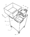
FIG. 1 is a diagram for explaining an oil and fat removal system including an oil and fat removal device of the present invention, FIG. 2 is an external perspective view of the fat and oil removal device in FIG. 1, and FIG. 3 is an AA cross-sectional explanation of FIG. FIG. 4 is a diagram showing the positional relationship between a cleaning tank dedicated to fats and oils and a second separation tank, and FIG. 5 is a diagram showing a state in which an auxiliary separator is attached to the processing tank of the oil and fat content removal apparatus of the present invention, FIG. 6 is a diagram for explaining oil and fat recovery in the auxiliary separator and the oil absorbing mat.
First, in FIG. 1, an oil removal system (whole structure) provided with the present invention will be described. 1 is a cleaning tank (sink) dedicated to oil and fat installed in a kitchen, and this cleaning tank (sink) 1 includes Liquid leftovers such as ramen soup, ordinary soup, sauce and dressing are washed away. Of course, this oil-and-fat dedicated washing tank (sink) 1 is also provided with a slat (filter) for preventing solids from flowing downstream, although not shown in the figure.
2 is an oil and fat removing device, and in this oil and
The drainage from which the oil / fat has been removed by the oil /
The oil /
By doing so, those who work in the Chinese restaurant, as a normal work, select the liquid residue containing fats and oils in the washing tank 1 dedicated to fats and oils and the waste water not containing fats and oils in the washing tank 5 respectively. It can drain.
As described above, the liquid residue containing oil and fat is drained to the sewer via the oil and
[0009]
Next, the overall configuration of the oil /
Moreover, the height of this oil-and-fat
In the figure, reference numeral 9 denotes a cleaning tank dedicated to fats and oils, and as described above, liquid left rice and the like, and
[0010]
Returning to FIG. 3,
Accordingly, the lower end of the
The peeling
The
From the standpoint of temperature control, it is advantageous to reduce the volume by dividing the
The
Therefore, even if the ambient temperature becomes the low viscosity or solidification temperature of animal and vegetable oils such as in winter, the oil does not become low viscosity or solidify in the tank. This is also true when the oil and
[0011]
Returning to FIG. 3,
As described above, the oil /
28 is a cleaning drain cap provided at the bottom of the
[0012]
Next, the fat removal process in the
The waste water containing the oil and fat that has entered the
The oil and fat floating on the surface is pumped up by the
On the other hand, the water from which the fats and oils have been removed passes through the bottom of the
Water containing no oil enters the
Thus, by installing the oil and fat
Moreover, since the
[0013]
【The invention's effect】
Since the present invention provides the system and apparatus as described above, it is possible to prevent contamination of sewers and the like, and to provide a great effect such that oils and fats can be collected and recycled.
In particular, it can prevent degradation of the grease trap function that could not withstand long-term use in the past, collect oil and fat regardless of the ambient temperature, and further improve the purification of wastewater flowing into the sewer with the double and triple oil removal function, etc. It has an effect.
[Brief description of the drawings]
FIG. 1 is a diagram for explaining an oil and fat removal system including an oil and fat removal device according to the present invention. FIG. 2 is an external perspective view of the oil and fat removal device in FIG. 1. FIG. FIG. 4 is a diagram showing the arrangement relationship between a cleaning tank dedicated to fats and oils and a second separation tank. FIG. 5 is a diagram showing a processing tank of the oil removing apparatus according to the invention. Fig. 6 is a diagram illustrating a state in which an auxiliary separator is attached. Fig. 6 is a diagram illustrating oil and fat recovery in the auxiliary separator and the oil absorbing mat. Fig. 7 is a diagram illustrating a conventional oil and fat removing system with illustrations. FIG. 8 is a diagram for explaining an oil removal system using a grease trap (interceptor) different from that in FIG. 7;
[Explanation of symbols]
DESCRIPTION OF SYMBOLS 1 Oil and fat-
31
36
Claims (4)
Priority Applications (1)
| Application Number | Priority Date | Filing Date | Title |
|---|---|---|---|
| JP27060898A JP3651753B2 (en) | 1998-09-08 | 1998-09-08 | Oil removal system and equipment |
Applications Claiming Priority (1)
| Application Number | Priority Date | Filing Date | Title |
|---|---|---|---|
| JP27060898A JP3651753B2 (en) | 1998-09-08 | 1998-09-08 | Oil removal system and equipment |
Publications (2)
| Publication Number | Publication Date |
|---|---|
| JP2000084542A JP2000084542A (en) | 2000-03-28 |
| JP3651753B2 true JP3651753B2 (en) | 2005-05-25 |
Family
ID=17488470
Family Applications (1)
| Application Number | Title | Priority Date | Filing Date |
|---|---|---|---|
| JP27060898A Expired - Lifetime JP3651753B2 (en) | 1998-09-08 | 1998-09-08 | Oil removal system and equipment |
Country Status (1)
| Country | Link |
|---|---|
| JP (1) | JP3651753B2 (en) |
Families Citing this family (4)
| Publication number | Priority date | Publication date | Assignee | Title |
|---|---|---|---|---|
| JP4527843B2 (en) * | 2000-05-02 | 2010-08-18 | 株式会社 大都技研 | Oil and fat removal device |
| JP4606574B2 (en) * | 2000-12-22 | 2011-01-05 | 株式会社 大都技研 | Oil and fat recovery device with dishwasher |
| JP2006102596A (en) * | 2004-10-01 | 2006-04-20 | Nakamura Kokusai Tsusho:Kk | Waste oil removing device |
| JP2010172895A (en) * | 2010-04-27 | 2010-08-12 | Daitogiken Inc | Oil-and-fat component removing device |
-
1998
- 1998-09-08 JP JP27060898A patent/JP3651753B2/en not_active Expired - Lifetime
Also Published As
| Publication number | Publication date |
|---|---|
| JP2000084542A (en) | 2000-03-28 |
Similar Documents
| Publication | Publication Date | Title |
|---|---|---|
| EP2788553B1 (en) | Apparatus for treating waste water | |
| CN106673243B (en) | Grease trapping device | |
| JP4128924B2 (en) | Separation and recovery processing system for solid residue and oil and fat, and separation and recovery method | |
| JP2010284578A (en) | Filter for wastewater | |
| US7427356B2 (en) | Fats, oil and grease interceptor | |
| KR100853253B1 (en) | Wastewater Collection Device for Kitchen | |
| CN106267986A (en) | Sewage residue removing device | |
| KR200459877Y1 (en) | Sewage treating trap capable of separating oil from leftover food | |
| JP4295399B2 (en) | Oil and fat removal equipment | |
| JP4346745B2 (en) | Oil and fat removal equipment | |
| JP4527843B2 (en) | Oil and fat removal device | |
| JP2000084542A (en) | Oil removal system and equipment | |
| NZ530182A (en) | Toilet system | |
| US12605654B2 (en) | Waste water treatment apparatus | |
| JP4270554B2 (en) | Sink system | |
| JP4606574B2 (en) | Oil and fat recovery device with dishwasher | |
| JP4605901B2 (en) | Washing table equipped with an oil and fat removal device | |
| JP2000042542A (en) | Automatic oil and scum processing equipment | |
| JP2001317117A (en) | Oil removal equipment | |
| CN215440047U (en) | Sewage treatment device | |
| JP4616443B2 (en) | Drainage system using sink to remove oil and fat from mixed oil drainage | |
| JP2001310184A (en) | Fat and oil recovery management system | |
| JP2005246343A (en) | Kitchen oil recovery equipment | |
| JP2010172895A (en) | Oil-and-fat component removing device | |
| JP3071824U (en) | Floating oil automatic recovery device |
Legal Events
| Date | Code | Title | Description |
|---|---|---|---|
| A621 | Written request for application examination |
Free format text: JAPANESE INTERMEDIATE CODE: A621 Effective date: 20040916 |
|
| A871 | Explanation of circumstances concerning accelerated examination |
Free format text: JAPANESE INTERMEDIATE CODE: A871 Effective date: 20041005 |
|
| A975 | Report on accelerated examination |
Free format text: JAPANESE INTERMEDIATE CODE: A971005 Effective date: 20041025 |
|
| A131 | Notification of reasons for refusal |
Free format text: JAPANESE INTERMEDIATE CODE: A131 Effective date: 20041101 |
|
| A521 | Written amendment |
Free format text: JAPANESE INTERMEDIATE CODE: A523 Effective date: 20041224 |
|
| TRDD | Decision of grant or rejection written | ||
| A01 | Written decision to grant a patent or to grant a registration (utility model) |
Free format text: JAPANESE INTERMEDIATE CODE: A01 Effective date: 20050201 |
|
| A61 | First payment of annual fees (during grant procedure) |
Free format text: JAPANESE INTERMEDIATE CODE: A61 Effective date: 20050217 |
|
| R150 | Certificate of patent or registration of utility model |
Free format text: JAPANESE INTERMEDIATE CODE: R150 |
|
| FPAY | Renewal fee payment (event date is renewal date of database) |
Free format text: PAYMENT UNTIL: 20080304 Year of fee payment: 3 |
|
| FPAY | Renewal fee payment (event date is renewal date of database) |
Free format text: PAYMENT UNTIL: 20140304 Year of fee payment: 9 |
|
| R250 | Receipt of annual fees |
Free format text: JAPANESE INTERMEDIATE CODE: R250 |
|
| R250 | Receipt of annual fees |
Free format text: JAPANESE INTERMEDIATE CODE: R250 |
|
| EXPY | Cancellation because of completion of term |