JP3643551B2 - Slot machine - Google Patents
Slot machine Download PDFInfo
- Publication number
- JP3643551B2 JP3643551B2 JP2001331587A JP2001331587A JP3643551B2 JP 3643551 B2 JP3643551 B2 JP 3643551B2 JP 2001331587 A JP2001331587 A JP 2001331587A JP 2001331587 A JP2001331587 A JP 2001331587A JP 3643551 B2 JP3643551 B2 JP 3643551B2
- Authority
- JP
- Japan
- Prior art keywords
- game
- medal
- game medium
- detection
- flow path
- Prior art date
- Legal status (The legal status is an assumption and is not a legal conclusion. Google has not performed a legal analysis and makes no representation as to the accuracy of the status listed.)
- Expired - Lifetime
Links
Images


Description
【0001】
【発明の属する技術分野】
本発明は、表示状態を変化させることが可能な可変表示装置の表示結果に応じて所定の入賞が発生可能なスロットマシンに関し、特には投入された遊技媒体のいわゆる飲み込みを防止することが出来るスロットマシンに関する。
【0002】
【従来の技術】
この種のスロットマシンは、一般的に例えば図20に示されるように、賭数を設定する際に使用する遊技媒体としてのメダルを投入可能なメダル投入口から投入されたメダルの流下通路R01、R02を構成する投入メダルセレクタ01が前面扉の裏面におけるメダル投入口の下方に設けられており、投入された真正なメダルは図示しない筐体内に導かれ、真正なメダルとは外径等が異なる偽メダルは返却されるようになっている。
【0003】
このような投入メダルセレクタ01は、前記流下通路R01、R02を流下するメダルの真偽を判別するメダル判別手段03と、該メダル判別手段により真正と判別されたメダルを検出するメダル検出手段04と、流下通路R02におけるメダル判別手段03と前記メダル検出手段04との間に位置し、ゲーム開始手段におけるゲームの開始要求の受付けに基づいて、メダル判別手段03により真正と判別されたメダルを遊技者に返却するために流下通路R2から排出するメダル排出手段05と、がそれぞれ設けられており、これらメダル検出手段やメダル排出手段の制御を行う制御部は、ゲーム開始手段におけるゲームの開始要求の受け付けに基づいてゲーム開始処理を実施した後における種々の不正行為を防止する目的で、ゲーム開始手段におけるゲームの開始要求の受付けに基づいてメダル検出手段04におけるメダルの検出を無効として、ゲーム開始中において賭数の設定処理等が実施されないようにしている。
【0004】
【発明が解決しようとする課題】
しかしながら、上記のようなスロットマシンにおいては、メダル投入口からメダル検出手段04まで所定距離あり、メダルが投入されてから検出されるまでに所定時間要するため、遊技者がメダルを投入するとほぼ同時か、早いタイミングでゲーム開始手段を操作すると、いわゆるメダルの飲み込みやメダル詰まりが発生するといった問題があった。
【0005】
すなわち、ゲーム開始手段が操作された時点でメダル排出手段05とメダル検出手段04との間を流下中のメダルがあり、このメダルがメダル検出手段04に達して検出されていてもその検出が完全に終了されていない場合、ゲーム開始手段の操作に基づくゲーム開始処理が優先されるようになっていたため、前述したように制御部によるメダルの検出が無効とされてしまい、メダル検出手段04を通過したにもかかわらず賭数やクレジットに加算されずに、筐体内に設けられたホッパータンク等に取り込まれてしまうことがあった。
【0006】
この現象を図21に示されるタイミングチャートに基づいて具体的に説明すると、まず、前回のゲームが終了した時点(Td1)において、前記制御部は、投入メダル検出手段04によるメダルの検出を有効にし、メダルの投入による賭数の設定を受け付ける状態とする。また、この状態においては賭数が設定されておらず、ゲームを開始することは出来ないため、ゲーム開始手段からのスタート操作を無効としている。
【0007】
Td1から所定時間経過後のTd2の時点で投入された1枚目のメダルが投入メダル検出手段04により検出され、投入メダル検出手段04からのメダル検出信号の受信が終了した時点(Td3)において、賭数の加算処理を実施する。これによりゲームを開始することが可能な状況となるため、スタート操作を有効とする。
【0008】
次いで2枚目のメダルが投入メダル検出手段04により検出された時点(Td4)から、この検出が終了する時点(Td5)を経て、3枚目のメダルが投入メダル検出手段04により検出される時点(Td6)までの間はスタート操作は有効のままとされる。
【0009】
そして、3枚目のメダルが投入メダル検出手段04により検出された時点(Td6)からこのメダル検出信号の受信が終了する時点(Td8)までの間の例えば所定時点(Td7)において、遊技者によりゲーム開始手段が操作されてスタート信号が出力された場合にあっては、スタート操作は有効とされているため、この時点(Td7)でスタート信号の出力に基づいてメダル検出手段04によるメダル検出を無効とし、ゲームを開始してしまう。
【0010】
すなわち、メダル検出中である時点(Td7)においてゲーム開始手段からのゲーム開始要求があった場合にはこれが受け付けられて投入メダル検出手段04によるメダルの検出が無効とされてしまうため、投入メダル検出手段04を通過中である検出中のメダルは、すでにメダル排出手段05を通過してしまっているので、遊技者に対してメダルが返却されることなく、しかも賭数もしくはクレジットとして加算されずに筐体内部のホッパータンク内に取り込まれてしまい、いわゆる飲み込みが発生するのである。
【0011】
また、メダルがメダル排出手段05を通過中である場合において、メダル排出手段05によるメダルの排出が上手く行われずにメダルが挟まる等してメダル詰まりが発生することがあった。
【0012】
本発明は、このような問題点に着目してなされたものであり、遊技媒体のいわゆる飲み込みを防止出来るスロットマシンを提供することを目的とする。
【0013】
【課題を解決するための手段】
上記課題を解決するために、本発明のスロットマシンは、1ゲームに対して賭数を設定することによりゲームが開始可能となるとともに、表示状態を変化させることが可能な可変表示装置の表示結果が導出表示されることにより1ゲームが終了し、該可変表示装置の表示結果に応じて所定の入賞が発生可能なスロットマシンであって、
前記賭数を設定するための遊技媒体を投入可能な遊技媒体投入口と、
該遊技媒体投入口から投入された遊技媒体が流下する流下通路と、
該流下通路を流下する遊技媒体の通路を遊技者に対して返却される遊技媒体が流下する返却遊技媒体流路に切り替える流路切替ソレノイドと、
前記流路切替ソレノイドが前記遊技媒体の流路を前記返却遊技媒体流路に切り替えたときに該遊技媒体が前記返却遊技媒体流路に排出されるように前記流下通路に形成された遊技媒体排出部と、
前記流下通路において前記遊技媒体排出部よりも該流下通路の下流側を流下する前記遊技媒体を検出する遊技媒体検出手段と、
前記遊技媒体検出手段が検出状態となった後、非検出状態となったことを条件に前記賭数の設定に使用可能な遊技媒体数を加算する遊技媒体数加算手段と、
遊技者の操作に基づいて前記ゲームの開始を要求するスタート信号を出力するゲーム開始手段と、
前記賭数の設定に使用可能な遊技媒体数が所定値に達したことを条件として、前記遊技媒体の流路を前記返却遊技媒体流路に切り替えるように前記流路切替ソレノイドを制御する制御手段と、
前記遊技媒体排出部よりも前記流下通路の下流側を流下する前記遊技媒体を検出する前記遊技媒体検出手段が検出状態となったときに、前記ゲーム開始手段のゲーム開始操作に基づくスタート信号の受付けを無効にし、該遊技媒体検出手段が非検出状態となったときに、前記スタート信号の受付けの無効を解除するゲーム開始操作無効手段と、
を備えることを特徴としている。
この特徴によれば、遊技媒体検出手段による遊技媒体の検出中においてゲーム開始手段のゲーム開始操作があった場合でも、該ゲーム開始手段の操作に基づくゲーム開始が無効とされることにより、前記ゲーム開始よりも遊技媒体検出手段による遊技媒体の検出が優位とされるため、いわゆる遊技媒体の飲み込みが防止される。
【0016】
本発明のスロットマシン前記流路切替ソレノイドが前記遊技媒体の流路を前記返却遊技媒体流路に切り替えたときに、前記流下通路における前記遊技媒体排出部から上流側を流下する前記遊技媒体を該流下通路から前記返却遊技媒体流路に強制的に排出させる遊技媒体排出手段を備えることが好ましい。
このようにすれば、ゲーム開始手段のゲーム開始操作がなされた時点で遊技媒体検出手段に到達していない遊技媒体を、前記遊技媒体検出手段により検出させることなく、確実に排出することが出来る。
【0017】
本発明のスロットマシンの前記遊技媒体排出部よりも前記流下通路の下流側を流下する前記遊技媒体検出手段は、前記流下通路の流路方向に向かって並設される少なくとも2つの検出センサからなり、
前記ゲーム開始操作無効手段は、最上流側の検出センサが検出状態となったときに前記スタート信号の受付けを無効にし、最下流側の検出センサが非検出状態となったときに、前記スタート信号の受付けの無効を解除することが好ましい。
本発明のスロットマシンの前記遊技媒体排出部よりも前記流下通路の下流側を流下する前記遊技媒体検出手段は、前記2つの検出センサと、該2つの検出センサの前記遊技媒体の流下方向に対して直交する方向に対向する箇所に設けられた補助検出センサと、からなり、前記2つの検出センサと前記補助検出センサとは前記遊技媒体を同時検出できるようになっていることが好ましい。
このようにすれば、遊技媒体の流下方向に向けて検出させることが出来、かつ、流下方向と反対側に引き出す際には検出されないような不正手段を用いた不正行為を効果的に防止出来る。
【0018】
本発明のスロットマシンは、前記スタート信号を受付け可能な旨を点灯により示すスタートランプを備えることが好ましい。
このようにすれば、ゲーム開始手段のゲーム開始操作が有効に受付けられる状態か否かを遊技者に対して報知できる。
本発明のスロットマシンは、遊技状態の制御を行う遊技制御部と、
遊技制御部から受信したコマンドに応じて演出制御を行う演出制御部と、
前記スタートランプを含む報知装置であって、遊技の進行に関わる情報を報知する必須報知装置と、
遊技の進行自体には影響を与えるものでなく、演出効果を主眼においた演出装置と、
を備え、
前記必須報知装置は前記遊技制御部によって制御され、前記演出装置は前記演出制御部によって制御されることが好ましい。
このようにすれば、演出制御部が故障したとしても、少なくとも遊技の進行に必要な情報が遊技者に提供されため、遊技者に不利な状態で遊技が進行してしまうことを防止できるばかりか、遊技制御部の制御の負荷が軽減される。
【0019】
【発明の実施の形態】
以下、本発明の実施の形態を図面に基づいて詳細に説明する。
【0020】
まず、本発明の実施例を図面を用いて説明すると、図1には、本発明が適用された遊技機の一例であるスロットマシンの全体正面図、図2及び図3にはスロットマシン1の内部構造図がそれぞれ示されている。スロットマシン1は、前面が開口する筐体2aと、この筺体2aの側端に回動自在に枢支された前面扉2bとから構成されており、前面扉2bの裏面に設けられた施錠装置3(図3参照)の鍵穴3aに挿入した所定のキーを時計回り方向に回動操作することにより施錠が解除されて前面扉2bを開放することができるようになっている。
【0021】
前面扉2bの前面上部には上部飾り枠4が設けられており、略逆台形状の上部には遊技効果ランプ部41、入賞図柄説明パネル5、液晶表示部15がそれぞれ設けられており、略楕円形状の中央部には、遊技パネル6や各種表示部が設けられている。上部飾り枠4の下部は遊技パネル6から前方に突出するように形成されており、この突出部にはメダル投入部34や各種操作ボタン35、36a、36b、37、40L、40C、40R、及びスタートレバー38等が設けられている。また、上部飾り枠4の中央部の周囲及び下部の左右側には、遊技効果ランプ部42〜45がそれぞれ設けられている。
【0022】
上部飾り枠4の下方には下部飾り枠7が設けられており、この枠内にはスロットマシン1の機種名称等が描かれたタイトルパネル8が設けられている。さらに下部飾り枠7の下方には、遊技媒体の一例となるメダルが払出されるメダル払出穴9が設けられているとともに、端部に灰皿10が設けられたメダル受皿11が設けられている。
【0023】
上部飾り枠4の上部左右側には、内部に設けられる高音用のスピーカ136a、136b(図3、図4参照)から出力される音を放音する放音部12a、12bがそれぞれ設けられているとともに、メダル払出穴9の側方には、内部に設けられる低音用のスピーカ137(図3、図4参照)から出力される音を放音する放音部13が設けられており、これら放音部12a、12b、13からは、各スピーカ136a、136b、137から出力される演出効果を高めるための音声やメロディ等の効果音が放音されるようになっている。
【0024】
遊技パネル6には、スロットマシン1の筐体2aに内設されたリール51L、51C、51Rを透視可能な透視窓14と、透視窓14の上方に位置する小役告知表示部20a、20b、20cと、透視窓14の左側に位置する1枚賭け表示部21、2枚賭け表示部22、23、3枚賭け表示部24、25と、透視窓14の右側に位置するゲームオーバー表示部26、リプレイ表示部27、ウェイト表示部28、スタート表示部29、投入指示表示部30と、透視窓14の下側に位置するクレジット表示部31、ゲーム回数表示部32、ペイアウト表示部33と、がそれぞれ設けられている。
【0025】
1枚賭け表示部21、2枚賭け表示部22、23、3枚賭け表示部24、25は遊技者がゲームに賭けた賭数を表示し、1枚賭け表示部21の内部には1枚賭けランプ112が、2枚賭け表示部22、23の内部には2枚賭けランプ113、114、3枚賭け表示部24、25の内部には3枚賭けランプ115、116がそれぞれ内蔵されている(図4参照)。各枚賭け表示部21〜25は、図のように透視窓14に描かれた5つの入賞ラインL1、L2、L2’、L3、L3’のいずれかと対応しており、賭数に応じて有効化された入賞ラインL1、L2、L2’、L3、L3’を識別可能に報知する有効ライン表示部と兼用されている。
【0026】
遊技パネル6における透視窓14の上部に設けられた小役告知表示部20a〜20cには、各々異なる入賞図柄が1つずつ描かれている。これら小役告知表示部20a〜20cは、所定の小役入賞を発生させることがスロットマシン1の制御部により許容されていること、すなわち、所定の小役入賞が内部当選していることを、その小役入賞に対応する入賞図柄が描かれた小役告知表示部20a〜20cの内部に内蔵された小役告知ランプ140a〜140c(図4参照)を点灯させることによって告知するための表示部であり、所定の条件が成立している場合に限り機能する。
【0027】
ゲームオーバー表示部26は、後述するビッグボーナスが終了することにより打ち止め状態となった場合、及び何らかのエラーが発生して遊技を進行させることができない状態となった場合に、その内部に内蔵されたゲームオーバーランプ117(図4参照)が点灯する。リプレイ表示部27は、リプレイ入賞が発生した場合に、その内部に内蔵されたリプレイランプ119(図4参照)が点灯する。スタート表示部29は、賭数が設定されることによりスタート操作をすることが可能となった場合に、その内部に内蔵されたスタートランプ118(図4参照)が点灯し、有効なスタート操作が検出されることにより消灯する。投入指示表示部30は、メダルを受付可能な状態である場合に、その内部に内蔵された投入指示ランプ111(図4参照)が点滅し、最大の賭数が設定され、かつ、クレジット数が予め定められた上限値に達した場合、ゲームが開始された場合等に消灯する。
【0028】
ウェイト表示部28は、ウェイトタイム中にスタート操作が検出された場合に、その内部に内蔵されたウェイトランプ139(図4参照)が点灯し、ウェイトタイムが経過した後に消灯する。ウェイトタイムは、ゲームがあまりに速く進行しすぎてしまうことを規制するために設定されたゲーム進行規制期間であり、このウェイトタイム中にスタート操作が検出されると、ウェイトタイムが経過した後にリールが始動するように設定されている。従って、十分な時間間隔を空けてゲームを進行する場合にはスタートレバー38の操作時にゲームの進行が規制されることはないが、短時間でゲームを進行しようとする場合にはウェイトタイムによってゲームの進行が一時的に規制され、ウェイトタイムが経過するまでの間リールの始動待ち状態となる。
【0029】
なお、このスロットマシン1では、前回のゲームでリールの回転が開始した時点を基準として、例えば4.1秒のゲーム進行規制期間が設定されており、前回のゲームでリールの回転が開始された時点から4.1秒が経過する前に、今回のスタート操作が検出された場合、ゲーム進行規制期間が経過した後にリールの回転が開始される。
【0030】
クレジット表示部31は、クレジット数が表示される。クレジットとは、遊技者所有の有価価値としてスロットマシン1内部の記憶部に記憶されているメダル数であり、メダル投入口へのメダルの投入、及び払出しのある入賞の発生等によって加算更新され、賭数を設定したり、精算操作に基づいてメダルを払出したりすることによって減算更新される。このスロットマシン1では、クレジットとして記憶可能な価値の上限値が最大でメダル50枚分とされており、この上限値(メダル50枚)に達した場合には投入指示表示部30が消灯する。そして、上限値を越えるクレジットの加算更新の要求が発生した場合にはその上限を越えるメダルがメダル払出穴9から払出される。
【0031】
ゲーム回数表示部32は、ビッグボーナス中のレギュラーボーナス入賞状況や、レギュラーボーナス中の入賞回数等を表示し、特にビッグボーナスが終了して打ち止め状態となった際には「END」という文字を表示して、遊技者に打ち止め状態である旨を報知する。さらにゲーム回数表示部32は、スロットマシン1に発生した各種の異常を表示するエラー表示器としても機能する。例えば、制御部により検出される異常種別には、「払出しすべきメダルの不足状態」、「メダル詰まり」、「払出条件が成立していないにも拘わらず入賞図柄の組み合わせが導出表示されたこと」等がある。これらの異常が制御部により検出された場合、その異常種別を特定可能なエラーコードが「E−1」や「E−2」等の態様により表示される。
【0032】
遊技パネル6から前面側に突出するように形成された上部飾り枠4の下部上面右側には、メダル投入口が形成されたメダル投入部34が設けられているとともに、左側には精算ボタン37、1枚BETボタン36a、MAXBETボタン36bがそれぞれ設けられている。
【0033】
1枚BETボタン36aは、1クレジットを賭ける際に押圧するボタンであり、MAXBETボタン36bは、1ゲームにおいて許容される賭数の最大数(本実施例ではメダル3枚分)をクレジットに記憶されている範囲内でゲームに賭ける際に押圧するボタンである。1枚BETボタン36aの内部にはBETボタンランプ121aが、また、MAXBETボタン36bの内部にはBETボタンランプ121bがそれぞれ内蔵されており(図4参照)、これらのBETボタンランプ121a、121bは、対応するBETボタンが押圧されて賭数を設定可能な状態にある場合に点灯し、賭数を設定不可能な状態の場合に消灯する。
【0034】
精算ボタン37は、記憶部に記憶されているクレジットの精算操作をする際に押圧するボタンであり、この精算ボタン37の押圧操作に伴い、クレジット表示部31に表示されているクレジット数が0になるまで減算更新されるとともに、クレジット相当数のメダルがメダル払出穴9から払出されるようになっている。
【0035】
上部飾り枠4の下部における前側面には、スタートレバー38、ストップボタン40L、40C、40R、メダル詰まり解除ボタン35がそれぞれ設けられている。スタートレバー38は、ゲームを開始する際に操作するレバーであり、賭数の設定終了後においてスタートレバー38を操作することにより各リール51L、51C、51Rの回転が開始される。
【0036】
各ストップボタン40L、40C、40Rは、ゲームが開始した後にリール51L、51C、51Rの回転を停止させる際に操作するボタンであり、ストップボタン40Lの内部には操作有効ランプ122Lが、ストップボタン40Cの内部には操作有効ランプ122Cが、ストップボタン40Rの内部には操作有効ランプ122Rが内蔵されている(図4参照)。これら操作有効ランプ122L、122C、122Rは、対応するストップボタン40L、40C、40Rの操作が有効である場合に点灯し、操作が無効である場合に消灯する。また、ストップボタン40L、40C、40Rが配列されたストップボタンユニット39は、ビッグボーナス入賞やレギュラーボーナス入賞の内部当選フラグが設定されている場合に、その内部に内蔵されたボーナス告知ランプ120(図4参照)が点灯する。
【0037】
メダル詰まり解除ボタン35は、メダル投入部34に投入されたメダルが内部で詰まった場合に、これを解消させる際に操作するボタンである。
【0038】
図2に示すように、筐体2a内略中央部には、複数種の図柄が印刷された透光性を有する帯状のリールシートが外周に巻回されたリール51L、51C、51R(ゲームの進行を実行するために用いるゲーム用リール)を有するリールユニット52からなる可変表示装置50が設けられている。それぞれのリール51L、51C、51Rは、各々に対応して設けられたステッピングモータからなるリールモータ54L、54C、54Rによりそれぞれ独立して縦方向に回転(駆動)、停止するように構成されており、各リール51L、51C、51Rが回転することにより、表示窓14には前記各種図柄が連続的に変化しつつ表示すようになっている。
【0039】
横方向に並設されたリール51Lとリール51Cとの間、及びリール51Cとリール51Rとの間には各リール間を閉塞する円弧状のリール間隠蔽部材53が設けられており、各リール間から内部が見えないようになっている。透視窓14のうち、リール間隠蔽部材53によって視界が仕切られることによって分割される3つの領域、すなわち、各リールが視認できる3つの領域部分を、各リールに対応させて左可変表示部、中可変表示部、右可変表示部(領域)と呼ぶ。
【0040】
透視窓14の各可変表示部からは、各リールに描かれた複数の図柄のうち、連続する3つの図柄が上段、中段、下段の位置に表示されるとともに、上段の上方部分には間もなく上段の位置に現れる図柄の一部が、下段の下方部分には間もなく可変表示部の下に隠れて見えなくなる図柄の一部がそれぞれ表示される。
【0041】
各リール51L、51C、51R内には各リールの基準位置を検出するリールセンサ56が設けられており、このリールセンサ56により所定の図柄の停止位置を導出できるようになっているとともに、各リール51L、51C、51Rにおける特定の表示領域(上、中、下段の表示領域)を裏面から個別に照射可能な複数のリールランプ55がそれぞれ上、中、下段に設けられており、これら各リールランプ55は、通常時において透視窓14に表示される各図柄を目立たせるように後方から点灯するバックライトとして機能するようになっている。
【0042】
筐体2aの背板85の上部前面には、後述するように主に遊技の進行を制御する制御部210や各種回路が設けられた遊技制御基板200が収納された収納ケース500が、取外し不能に固定されている。また、可変表示装置50を構成するリールユニット52における前方からみて右側の側板の内面上部には後述するリール中継基板203が、また、その下部には後述するリールランプ中継基板204がそれぞれ取り付けられている。
【0043】
筐体2aを前面側からみて右側の側板87の内面におけるリールユニット52の側方位置には、後述する外部出力基板205が取り付けられている。
【0044】
リールユニット52の下方には、メダル投入部34から投入されたメダルを貯留するホッパータンク57が、筐体2aを構成する下板上面に固設された案内レール58を介して前方に引出し可能に配設されている。また、ホッパータンク57の右側にはホッパータンク57からオーバーフローしたメダルが貯留されるオーバーフロータンク59が設けられている。このオーバーフロータンク59内にはメダルを検出可能な満タンセンサ60が設けられており、内部に貯留されたメダル貯留量が所定量以上となったことを報知できるようになっている。
【0045】
ホッパータンク57の下方部分にはホッパーモータ62が設けられており、このホッパーモータ62が回転することによりホッパータンク57内のメダルがメダル排出口63から排出される。排出されたメダルは、メダル排出口63の近傍に設けられる払出しメダルセンサ61により検出された後、後述する返却メダル流路73を介してメダル払出穴9よりメダル受皿11まで払い出される。なお、ホッパーモータ62は、払出しメダルセンサ61により所定枚数の払出メダルが検出された時点で停止するように制御されている。
【0046】
ホッパータンク57の側部には、メイン電源をON/OFFするメインスイッチ部65と、ビッグボーナスの終了時や遊技中にエラーが生じた場合等において再びゲームを続行可能な状態にリセットするための第2リセットボタン66と、入賞確率を変更可能とする設定ボタン67と、自動精算機能をON/OFFする自動精算選択スイッチ部68と、自動打止め機能をON/OFFする打止め選択スイッチ部69と、遊技場の管理者等が所持する特定のキーを挿入した状態で所定の操作を行うことで前記設定ボタン67の操作を可能、不可とする設定キー挿入部70と、が前面に設けられた電源ユニット64が配設されている。
【0047】
入賞確率は、本実施例では、予め定められた入賞確率の値を6つのパターンの設定値として記憶しており、これを上記設定ボタン67を操作することにより任意に選択することで、入賞確率の異なる遊技を行うことが可能となる。
【0048】
図3に示すように、前面扉2bの裏面略中央部には、メダル投入部34から投入されたメダルをホッパータンク57に導く流下通路を構成する投入メダルセレクタ71が固設されている。この投入メダルセレクタ71の上流側には偽メダル排出部72が設けられており、大きさや厚みが真正メダルと異なる偽メダルは、投入メダルセレクタ71の下方に設けられる返却メダル流路73の上部投入口に排出され、メダル払出穴9を介してメダル受皿11に返却されるようになっている。
【0049】
偽メダル排出部72の下流側には、流下するメダル流路を選択的に切替可能とする流路切替ソレノイド107が設けられている。通常時において流路切替ソレノイド107は励磁されており、流下するメダルは流路を切り替えられることなく流下し、その下流側に設けられた遊技媒体検出手段としての投入メダルセンサ106a、106b、及び補助検出手段としての投入メダルセンサ106cにより検出された後、ホッパータンク57内に貯留されるようになっている。そして、例えばスタートレバー38が操作されることによりリール51L、51C、51Rが回転してゲームが開始されている場合や、クレジット数が50に達している場合、または遊技者にメダルが払出されている場合において流路切替ソレノイド107の励磁が解除されて流路が切替わり、メダルは返却流路を経て返却メダル流路73に導かれるようになっている。なお、この投入メダルセレクタ71の詳細に関しては後述することとする。
【0050】
前面扉2bの裏面上部には、遊技に関連する所定の演出を制御する制御部230や各種回路等が設けられている演出制御基板201が収納された収納ケース550が取外し不能に固定されている。
【0051】
収納ケース550の左右側には、高音用のスピーカ136a、136bが前述した放音部12a、12bにそれぞれ臨むように固設されているとともに、前面扉2bにおける下部所定箇所裏面側には、低音用のスピーカ137が放音部13に臨むように固設されており、例えばメダルのメダル投入部34への投入、スタートレバー38の操作、ストップボタン40L、40C、40Rの操作等、遊技中において各種動作がなされた場合や、特定の図柄の組み合わせが有効化された有効ライン上に揃って表示されて所定の入賞条件が成立した場合、あるいはビッグボーナスやレギュラーボーナスが実行されている場合等の各種遊技状態において、該遊技状態に対応する所定の遊技効果音等が各スピーカ136a、136b、137から出力されるようになっている。
【0052】
次に、遊技者が遊技(ゲーム)を行うための操作や、該操作に伴う各種装置の作動状況を説明する。
【0053】
ゲームを開始する場合は、遊技者はまず投入指示ランプ111が点灯または点滅している時に、メダルやクレジットを使用して所望の大きさの有価価値を賭けて所望の大きさの賭数を設定する。賭数は、メダルをメダル投入部34から投入するか、あるいはクレジットを使用することにより設定できるようになっている。クレジットを使用するにはMAXBETボタン36b、または1枚BETボタン36aを押圧すればよく、MAXBETボタン36bが押圧されるとクレジット表示部31に表示されたクレジット数が、本実施例で1ゲームにおいて許容される賭数の最大数である「3」だけ減算表示されてメダル3枚分の賭数が設定され、また、1枚BETボタン36aが押圧されるとクレジット表示部31に表示されているクレジット数が「1」だけ減算表示されてメダル1枚分の賭数が設定される。なお、クレジット表示部31に表示されるクレジット数が3に満たない場合、設定可能な賭数の範囲はそのクレジット数の範囲内に限られる。
【0054】
遊技者により1枚のメダルがメダル投入部34から投入されるか、1枚BETボタン36aが押圧操作されると賭数が「1」に設定されるとともに、中段の横1列の入賞ラインL1が有効となり、この入賞ラインL1が有効となった旨を示す1枚賭けランプ112(図4参照)が点灯する。続けて2枚目のメダルがメダル投入部34から投入されるか、1枚BETボタン36aが2回押圧操作されると賭数が「2」に設定され、上、中、下段の横3列の入賞ラインL1、L2、L2’が有効となり、これらの入賞ラインL1、L2、L2’が有効となった旨を示す1枚賭けランプ112、2枚賭けランプ113、114が点灯する。続けて3枚目のメダルがメダル投入部34から投入されるか、1枚BETボタン36aが3回押圧操作されるか、あるいはMAXBETボタン36bが押圧されると賭数が「3」に設定され、上、中、下段の横3列の入賞ラインL1、L2、L2’及び斜め対角線上2列の入賞ラインL3、L3’が有効となり、これらの入賞ラインL1、L2、L2’、L3、L3’が有効となった旨を示す1枚賭けランプ112、2枚賭けランプ113、114、3枚賭けランプ115、116が点灯する。なお、賭数が最大数である「3」に設定された場合には、それを越える賭数を設定することはできないためBETボタンランプ121a、121bは消灯する。
【0055】
そして上記のように少なくとも最小数である「1」の賭数が設定された時点でスタートレバー38の操作が有効に受付けられる状態、すなわち、ゲームが開始可能な状態となり、このスタートレバー38の操作が有効に受付けられる状態になった旨を示すスタートランプ118が点灯される。
【0056】
なお、このようなメダルやクレジット等の設定される賭数に応じて有効化される有効ラインの本数、及び形状等は任意に変更可能であり、本実施例の形態に限定されるものではない。また、賭数に応じて有効化される有効ラインの本数も任意に設定変更可能であり、例えば1枚のメダル投入により上記5本全ての入賞ラインL1、L2、L2’、L3、L3’が有効化されるようになっていてもよい。
【0057】
スタートランプ118が点灯している状態でスタートレバー38を押圧操作すれば、可変表示装置50が作動して各リール51L、51C、51Rが回転し、透視窓14には複数種類の図柄が連続的に変化するように表示される。前述したようにリール51L、51C、51Rの回転が開始されてから所定時間が経過すれば各ストップボタン40L、40C、40Rの操作が有効になり、これらストップボタン40L、40C、40Rの操作が有効になった旨を示す操作有効ランプ122L、122C、122Rが点灯する。操作有効ランプが点灯している状態で遊技者がいずれかのストップボタン40L、40C、40Rを押圧操作すれば、対応する操作有効ランプ122L、122C、122Rが消灯するとともに、対応するリール51L、51C、51Rの回転が停止され、透視窓14からは対応する可変表示部の上、中、下段に図柄が表示される。
【0058】
また、遊技者がストップボタン40L、40C、40Rを押圧操作しない場合には、所定時間(例えば30秒)が経過した時点で例えばリール51L、51C、51Rの優先順序で自動的に順次停止する。
【0059】
そして3つのうちいずれか2つのリールの回転が停止された時点で、賭数に応じて有効化されたいずれかの入賞ラインL1、L2、L2’、L3、L3’上に同種の図柄が揃って停止表示された場合にはリーチが成立する。
【0060】
さらに全てのリール51L、51C、51Rが停止された時点で、賭数に応じて有効化されたいずれかの入賞ラインL1、L2、L2’、L3、L3’上に予め定められた図柄の組み合わせが表示された場合は入賞となり、各種遊技効果ランプ部41〜45の内部に内蔵された遊技効果ランプ130〜134(図4参照)や入賞ラインL1、L2、L2’、L3、L3’に対応するリールランプ55等が点灯するとともに、スピーカ136a、136b、137から効果音等が出力されること等による演出が実行される。そして、入賞内容に対応して予め定められた所定枚数のメダルが遊技者に対してクレジットとして払出されてクレジット表示部31に表示されたクレジット数が加算更新される。また、クレジット数が上限数に達した場合には、メダルが直接メダル払出穴9から払い出される。これらメダルの払出し枚数はペイアウト表示部33に表示される。
【0061】
また、特に予め定められた特別図柄の組み合わせが表示されて大当り入賞が発生した場合等にあっては、メダルの払出しが行なわれるとともに、通常遊技状態とは異なるとともに、遊技者にとって有利な、すなわち大量のメダルを獲得できる特別遊技状態が発生し、後述するようなビッグボーナス(以下BBと称する)やレギュラーボーナス(以下RBと称する)が遊技者に対して遊技価値として付与されるようになっている。
【0062】
なお、このように入賞することにより遊技者に対して付与される「遊技価値」は、メダル及びクレジット等の有価価値に限らず、上記のように大当たり入賞した場合等において遊技者に対して付与されるBBやRB等、遊技に関連する特典全てを含む。
【0063】
本実施例におけるスロットマシン1にあっては、賭数に応じて有効化されたいずれかの入賞ラインL1、L2、L2’、L3、L3’上に例えば「BAR−BAR−BAR」の図柄が揃えば、大当りであるRBに入賞したことになり、「BAR−BAR−BAR」の図柄が揃ったことの対価として例えば15枚のメダルが払出されるとともに、遊技者にとって有利な遊技状態であるRB(レギュラーボーナス)状態が発生し、以下に説明するレギュラーボーナスゲームが遊技価値として遊技者に対して付与される。このRB中では、プラム図柄のぞろめが揃うことにより所定枚数のメダルが払出されるJac賞の入賞が高確率で発生するJacゲームが最大で12回提供されるとともに、このJacゲームが12回実行されるか、あるいはJacゲームが12回に達する前にJac賞の入賞が8回発生されるか、いずれかの条件が満たされた時点で終了する。したがって、遊技者は12回のJacゲーム中に最大8回のJac賞の入賞の機会を得ることができる。
【0064】
一方、有効化された入賞ラインL1、L2、L2’、L3、L3’上に、例えば「黒7−黒7−黒7」または「白7−白7−白7」が揃えば、大当りであるBB(ビッグボーナス)に入賞したことになり、「黒7−黒7−黒7」または「白7−白7−白7」の図柄が揃ったことの対価として例えば15枚のメダルが払出されるとともに、遊技者にとって有利な特別遊技状態であるBB(ビッグボーナス)状態が発生し、以下に説明する小役ゲームが遊技価値として遊技者に対して付与される。具体的に説明すると、このBB中では、小役図柄(実施例ではスイカ、ベル、プラム)のぞろめが高確率で揃って所定枚数のメダルの払出しをともなう小役の入賞が高確率で発生する小役ゲームが最大で30回提供されるとともに、この小役ゲームを30回実行するまでの間にプラム図柄のぞろめが揃ってJacIn賞が入賞した場合には、特別遊技状態である前述のRB状態が発生してレギュラーボーナスゲームが提供されるようになっている。このRBは、BB中における発生可能な最大回数が予め定められており、本実施例では最大で3回発生し得るようになっている。そしてこのBBは、30回の小役ゲームを実行して終了する場合か、あるいは小役ゲームを30回に実行する前に3回のRBが提供されて3回目のRBが終了する場合のうち、少なくともいずれか一方の条件が満たされた時点で終了する。
【0065】
また、前記特別遊技状態以外の通常の遊技状態である場合においては、同種の図柄が有効化された1つの有効ライン上に揃って所定の賞が成立した場合には、その図柄の種類に応じて予め定められた所定枚数のメダルが遊技者に付与される。
【0066】
なお、賭数に応じて有効化された有効ラインが複数本存在する場合において、前述した単図柄のようにメダルが払出される図柄(図柄の組み合わせ)が複数本の入賞ライン上において同時に成立した場合には、各入賞ライン上の図柄の組み合わせによって付与されるメダル枚数の合計枚数に相当するメダルが付与されるのが原則である。しかし、1ゲームにおいて遊技者に付与されるメダルの上限が15枚と定められているために、15枚を越える場合にはその16枚目以降のメダルが無効となる。
【0067】
本実施例においては、前述のように通常遊技状態において黒7−黒7−黒7(黒7賞)、白7−白7−白7(白7賞)、BAR−BAR−BAR(BAR賞)、スイカ−スイカ−スイカ(スイカ賞)、チェリー(チェリー賞)、ベル−ベル−ベル(ベル賞)、黒7−スイカ−スイカ(黒7スイカ賞)、白7−スイカ−スイカ(白7スイカ賞)BAR−スイカ−スイカ(BARスイカ賞)またはプラム−プラム−プラム(再遊技;リプレイ)が入賞の対象となっており、そのうち黒7、または白7の図柄、及びBARの図柄のみが遊技者にとって利益の大きな賞である大当り入賞(BB、RB)の対象となる特別図柄とされて、その他スイカ、チェリー、ベルまたはプラム(再遊技)は遊技者にとって利益の小さな賞である小役入賞の対象となる図柄とされている。
【0068】
このような各賞の対象となる図柄の組み合わせ、及び該図柄の組み合わせに対応する払出しメダル枚数(入賞の発生確率等も含む)は、通常ゲーム時、及びBB時、RB時に対応してそれぞれ予め定められており、これらの設定内容は後述する制御部210のROM213に記憶された入賞判定テーブルに登録されている。
【0069】
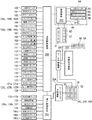
図4は、スロットマシン1に設けられた各種基板と電気部品との接続状況を説明するためのブロック図である。また、図5は、遊技制御基板200に設けられた制御部210の構成と、演出制御基板201に設けられた制御部230の構成と、を説明するためのブロック図である。
【0070】
スロットマシン1に設けられた各種基板のうち、遊技制御基板200によって主に遊技状態が制御され、演出制御基板201によって遊技状態に応じた演出制御等が実施される。また、電源基板202にはスロットマシン1の外部から電源が供給される。この電源基板202には、AC100Vの電源の供給を受けるための電源コード84と、メインスイッチ80とが接続されている。
【0071】
遊技制御基板200は、演出制御基板201、電源基板202、リール中継基板203と配線接続されているとともに、リール中継基板203を介して外部出力基板205と、また、演出制御基板201を介してリールランプ中継基板204と接続されている。
【0072】
遊技制御基板200の制御部210は、遊技状態がRB状態であることを示すRB中信号や、遊技状態がBB状態であることを示すBB中信号、各リール51L、51C、51Rに対応するリールモータ54L、54C、54Rを制御するためのリール制御信号(モータ位相信号)、ゲーム開始時において確定された賭数に応じて出力されるメダルin信号、メダルの払出に応じて出力されるメダルout信号、後述するデータ信号並びにストローブ信号などを、リール中継基板203を介して外部出力基板205からスロットマシン1の外部に出力する制御を行う。なお、ストップスイッチ103L、103C、103Rの操作がなされた旨を示すストップスイッチ信号は、後述するようにストップスイッチ103L、103C、103Rから直接出力された信号である。
【0073】
遊技制御基板200には、各種のスイッチ、センサ、ランプ、及び表示器からの配線が接続されている。
【0074】
例えば、電源基板202に配線接続された設定スイッチ83、設定キースイッチ82、第2リセットスイッチ81、払出しセンサ61、及びホッパーモータ62は、電源基板202によって中継されて遊技制御基板200と配線接続されており、それぞれのスイッチ及びセンサの検出信号は、遊技制御基板200の制御部210に入力される。また、制御部210は、メダルの払出し条件(メダルを払出す必要のある入賞の発生、精算スイッチ104からの検出信号の入力)が成立すると、ホッパーモータ62に制御信号を出力して、所定数のメダルを払出す払出し制御を実行する。
【0075】
リール中継基板203に配線接続されたリールモータ54L、54C、54R、及びリールセンサ56は、リール中継基板203によって中継されて遊技制御基板200に配線接続されており、リールセンサ56の検出信号は、遊技制御基板200の制御部210に入力される。リールランプ55は、リールランプ中継基板204によって中継されて演出制御基板201に配線接続されている。遊技制御基板200の制御部210は、始動条件(スタートスイッチ102の検出信号の入力)が成立すると、リールモータ54L、54C、54Rに制御信号を出力してリールの変動を開始させた後、表示結果を導出表示させる可変表示制御を実行する。
【0076】
遊技制御基板200に配線接続されたスイッチのうち、1枚BETスイッチ100は1枚BETボタン36aの操作を検出し、MAXBETスイッチ101はMAXBETボタン36bの操作を検知するスイッチであり、スタートスイッチ102はスタートレバー38の操作を検出するスイッチであり、左、中、右ストップスイッチ103L、103C、103Rは、左、中、右ストップボタン40L、40C、40Rの操作を検出するスイッチである。精算スイッチ104は、精算ボタン37の操作を検出するスイッチであり、第1リセットスイッチ105は、施錠装置3の鍵穴3aに挿入したキーによるスロットマシン1のリセット操作を検出するスイッチである。
【0077】
投入メダルセンサ106a〜106cは、メダル投入部34に投入されたメダルを検出するセンサである。流路切替ソレノイド107は、メダル投入部34に投入されたメダルの流路をホッパータンク57側もしくはメダル払出穴9側に切り替えるためのソレノイドである。
【0078】
ゲーム回数表示器108はゲーム回数表示部32を構成する表示器であり、クレジット表示器109はクレジット表示部31を構成する表示器であり、ペイアウト表示器110はペイアウト表示部33を構成する表示器である。
【0079】
投入指示ランプ111は、投入指示表示部30に内蔵されるランプであり、1枚賭けランプ112は1枚賭け表示部21に、2枚賭けランプ113、114は2枚賭け表示部22、23に、3枚賭けランプ115、116は3枚賭け表示部24、25に内蔵されるランプである。
【0080】
ゲームオーバーランプ117は、ゲームオーバー表示部26に内蔵されるランプであり、スタートランプ118は、スタート表示部29に内蔵されるランプであり、リプレイランプ119は、リプレイ表示部27に内蔵されるランプであり、なお、ボーナス告知ランプ120はストップボタンユニット39に内蔵されるランプである。BETボタンランプ121aは1枚BETボタン36aに、BETボタンランプ121bはMAXBETボタン36bに内蔵されるランプである。左操作有効ランプ122Lは、左ストップボタン40Lに内蔵されるランプであり、中操作有効ランプ122Cは、中ストップボタン40Cに内蔵されるランプであり、右操作有効ランプ122Rは、右ストップボタン40Rに内蔵されるランプであり、ウェイトランプ139はウェイト表示部28に内蔵されるランプである。
【0081】
電源基板202あるいはリール中継基板203を介して、あるいはこれらの基板を介することなく遊技制御基板200に配線接続された各種ランプ及び表示器は、遊技制御基板200に搭載された制御部210によって制御される。また、制御部210は、遊技制御基板200に接続され、または、電源基板202あるいはリール中継基板203を介して遊技制御基板200に接続された各種スイッチ及びセンサの検出信号を受け、遊技状態を制御する。
【0082】
特に、制御部210によって制御される「クレジット表示器109、ゲーム回数表示器108、ペイアウト表示器110、投入指示ランプ111、1枚賭けランプ112〜3枚賭けランプ116、スタートランプ118、リプレイランプ119、ボーナス告知ランプ120、ゲームオーバーランプ117、左、中、右操作有効ランプ122L、122C、122R、ウェイトランプ139」は、遊技の進行に関わる情報を報知するものであり、それが機能しなければ遊技を行うことに支障が出るような、いわば“必須報知装置”といえる。これらの“必須報知装置”が遊技状態を制御する制御部210によって制御されるために、たとえ、演出制御基板201が故障したとしても、少なくとも遊技の進行に必要な情報が遊技者に提供される。このため、遊技者に不利な状態で遊技が進行してしまうことを防止できる。
【0083】
遊技制御基板200に設けられた制御部210は、図5に示すように、制御動作を所定の手順で実行することのできるCPU(Central Processing Unit)211と、CPU211の制御プログラムを格納するROM(Read Only Memory)213と、必要なデータの書き込み及び読み出しができるRAM(Random Access Memory)212と、CPU211と外部回路との信号の整合性をとるためのI/Oポート214とを含む。
【0084】
また、遊技制御基板200には、電源投入時にCPU211にリセットパルスを与える初期リセット回路217と、CPU211にクロック信号を与えるクロック発生回路218と、クロック発生回路218からのクロック信号を分周して割込パルスを定期的にCPU211に与えるパルス分周回路(割込パルス発生回路)219と、一定範囲の乱数を高速で連続的に発生している乱数発生回路221と、乱数発生回路221から乱数をサンプリングするサンプリング回路222と、バッファ回路220とが設けられる。さらに、遊技制御基板200には、各種スイッチからの信号が入力されるスイッチ回路215や、モータ回路216、その他、図示しないソレノイド回路等が設けられている。さらに、遊技制御基板200には、停電時にRAM212の記憶を保持させるためのバックアップ電源223が設けられている。RAM212には、各種表示器(クレジット表示器109、ゲーム回数表示器108、ペイアウト表示器110)に表示するべき情報、賭数、内部当選フラグ、各種遊技状態等を示す各種設定フラグ、出玉率の設定値等、遊技に必要な情報や後述するデータ送信テーブル等の試験信号の出力に必要な情報が記憶され、停電時にこれらの情報がバックアップされるために、停電の回復後に、停電発生前の状態に復帰できる。
【0085】
制御部210のROM213には、前記制御プログラムに加えて、各賞に対応するサンプリング値の割り当て範囲が、各入賞確率の設定値並びにゲームの賭数、遊技状態(通常ゲーム時、BB時、RB時)別に対応してそれぞれ登録されているとともに、各賞に対応する入賞図柄の組み合わせやメダルの払出枚数、入賞に伴い設定される各種設定内容が、各遊技状態(通常ゲーム時、BB時、RB時)別に対応してそれぞれ登録されている入賞判定テーブル(図示略)が記憶されている。この入賞判定テーブルには、前述のように各賞のサンプリング値の割り当て範囲が登録されており、これらサンプリング値の割り当て範囲の設定により、後述の内部抽選処理において内部当選可能な賞の入賞確率が設定されるようになっている。
【0086】
また、前記ROM213には、各リール51L、51C、51Rの図柄番号毎に、各リール51L、51C、51Rの停止操作がなされてから該当するリールが停止するまでに移動する図柄のコマ数が、遊技状態(通常ゲーム時、BB時、RB時)や内部当選フラグの成立状況、他のリールの回転状況、有効ラインL1、L2、L2’、L3、L3’上に位置する各リール51L、51C、51Rの図柄番号等の各種状況に応じて各々登録されているリール制御テーブル(図示略)が記憶されている。
【0087】
遊技制御基板200の制御部210から演出制御基板201へは、バッファ回路220を介して後述する各種コマンドが出力される。バッファ回路220は、遊技制御基板200の内部から外部への信号の出力を許容するが遊技制御基板200の外部から内部へ信号が入力されることを阻止するように機能する。このため、遊技制御基板200と演出制御基板201との間において、遊技制御基板200から演出制御基板201への一方向通信が担保され、コマンドの伝送経路を介して遊技制御基板200に信号を入力させて不正な制御動作を行わせる不正行為を防止できる。
【0088】
演出制御基板201には、遊技効果ランプ130〜134と、液晶表示器135と、放音部12a、12b、13に内蔵されるスピーカ136a、136b、137と、タイトルパネル8及び遊技パネル6を内側から照らす各蛍光灯138と、小役告知ランプ140a、140b、140cと、がそれぞれ接続され、さらに、リールランプ中継基板204を介してリール51L、51C、51Rに内蔵されているリールランプ55が接続されている。
【0089】
演出制御基板201には、制御部230と、各スピーカ136a、136b、137から音を出力させるためのスピーカ駆動回路235と、液晶表示器135を表示制御するための表示駆動回路236と、各種ランプを点灯あるいは点滅させるためのランプ駆動回路237と、バックアップ電源238とが搭載されている。
【0090】
制御部230は、CPU231と、必要なデータの書き込み、及び書き出しができるRAM232と、制御プログラムを格納するROM233と、I/Oポート234と、を含む。RAM232の記憶データはバックアップ電源238によりバックアップされているため、制御部230は、停電の回復時に停電発生前に記憶されていたデータに基づいて演出制御を再開できる。
【0091】
制御部230のROM233には、遊技制御基板200から送信される各種コマンドに基づいてゲーム状態や内部当選状況等を特定可能なデータが登録されたコマンドテーブルが記憶されているとともに、前記遊技制御基板200から送信される各種コマンドに基づき特定されるゲーム状況に対応して演出パターンを定めた演出パターンテーブルが記憶されている。この演出パターンテーブルは、各遊技効果ランプ130〜134、液晶表示器135、各スピーカ136a、136b、137、各蛍光灯138、小役告知ランプ140a〜140c、別に分類されており、例えば所定の遊技状態を示すコマンドを受信した場合、制御部230はその遊技状態に応じた演出パターンを抽出し、この抽出した演出パターンに応じて各遊技効果ランプ130〜134、液晶表示器135、各スピーカ136a、136b、137、各蛍光灯138、小役告知ランプ140a〜140c、及びリールランプ55等を制御する。
【0092】
演出制御基板201によって制御される各遊技効果ランプ130〜134、液晶表示器135、各スピーカ136a、136b、137、各蛍光灯138、小役告知ランプ140a〜140c、リールランプ55は、遊技制御基板200によって制御される各種表示器などに比較すると、それが機能しなくても遊技の進行自体には影響を与えるものでなく、演出効果を主眼においた、いわば、“演出装置”と呼べるものである。このため、たとえ、演出制御基板201に故障が発生したとしても、遊技者に不利な状況が提供されてしまうことはないばかりか、制御部210の制御の負荷が軽減される。
【0093】
図5に戻って、スタートスイッチ102の検出信号は、スイッチ回路215を介して制御部210に入力されるとともに、サンプリング回路222に入力される。制御部210は、スタートスイッチ102の検出信号を受け、モータ回路216を介してリール制御信号を出力する。このリール制御信号はリール中継基板203を介して各リール51L、51C、51R別に設けられたリールモータ54L、54C、54Rに入力される。また、リール制御信号は、リール中継基板203及び外部出力基板205を介して外部出力される。
【0094】
これにより、各リール51L、51C、51Rが変動し始める。また、リール制御信号の伝送経路は、リール中継基板203においてリールモータ54L、54C、54R側と外部出力基板205側とに分岐されており、外部出力基板205側へ出力されたリール制御信号は、外部出力基板205からスロットマシン1の外部へも出力される。このように、外部出力基板205から出力されるリール制御信号は、外部出力用に加工された信号ではなく、リールモータ54L、54C、54Rを駆動制御する信号そのものである。
【0095】
一方、サンプリング回路222は、スタートスイッチ102の検出信号が入力されたタイミングで乱数発生回路221から1個の乱数をサンプリングし、その乱数をCPU211に引き渡す。CPU211は、そのサンプリングされた乱数と、ROM213内に格納されている入賞判定テーブルとを参照して、入賞の発生を許容するか否かを入賞役別に決定し、その決定結果をRAM212に記憶させる。これにより、スタート操作がされたタイミングとほぼ等しいタイミングで、後述の内部抽選処理が実施され、入賞役の当選の有無が決定される。制御部210は、その後、入賞役別の当選結果に応じてリールを制御する。
【0096】
また、各ストップスイッチ103L、103C、103Rから出力されたストップスイッチ信号は、遊技制御基板200、リール中継基板203、および外部出力基板205を往復する信号経路を伝送された後、遊技制御基板200のスイッチ回路215に入力される。さらに、ストップスイッチ103L、103C、103Rから出力されたストップスイッチ信号は直接、外部出力基板205を介して外部に出力されるように構成されている。
【0097】
ストップスイッチ信号の入力を受けた制御部210は、ストップスイッチ信号に対応するリールモータ54L、54C、54Rのリール制御信号の出力を所定のタイミングで停止する。これに基づき外部出力基板205から出力されるリール制御信号も停止される。
【0098】
外部出力基板205から出力されるリール制御信号や各ストップスイッチ信号は、例えば、第3者機関が型式試験を行う際に利用可能である。この型式試験では、例えば、各ストップボタン40L、40C、40Rの操作から190ms以内に各ストップボタン40L、40C、40Rに対応する各リール51L、51C、51Rが停止するか否かが確認される。このスロットマシン1の場合、各ストップスイッチ103L、103C、103Rから出力されたストップスイッチ信号が直接、外部出力基板205から出力されるために、各ストップボタン40L、40C、40Rが操作されたタイミングをスロットマシンの外部で正確に把握できる。同様に、モータ回路216から出力されるリール制御信号が直接、外部出力基板205から出力されるために、各リール51L、51C、51Rの始動および停止タイミングをスロットマシンの外部で正確に把握できる。このため、外部出力基板205から出力される信号を用いて、「各ストップボタン40L、40C、40Rの操作から190ms以内に各ストップボタン40L、40C、40Rに対応する各リール51L、51C、51Rが停止するか否かの試験」を行った場合には、正確な試験結果が得られる。また、「遊技制御基板200の制御部210で一旦、信号を取り込んでから外部出力基板205に信号を出力するような構成」とした場合には、遊技制御基板200側で信号を加工して出力するような不正がなされるおそれもあるが、本実施の形態によると、かかる不正行為をも防止できる。
【0099】
次に、本実施例における制御部210がゲームの進行に伴い実行する各種制御内容を、図6のフローチャートに基づいて以下に説明していく。
【0100】
まずSa1においては、ゲームスタートに備えるための初期処理を実行する。具体的には、次のゲームの遊技状態を設定し、この設定した遊技状態を示す遊技状態コマンドを演出制御基板201の制御部230に送信した後、投入指示ランプ111を点灯させ、メダルやクレジットを受付け可能な状態で待機する。
【0101】
特に電源の立ち上げ時等においては、前述した各種装置の接続、及び作動状況、各種フラグの成立状況を確認し、例えば設定ボタン67の設定状況に基づく入賞確率の設定や、リール51L、51C、51Rの初期位置の設定等の種々の設定を実行した後、次のゲームの遊技状態を設定し、投入指示ランプ111を点灯させ、メダルやクレジットを受付け可能な状態で待機する。
【0102】
Sa2においては、メダルの賭数が選択され、スタートレバー38が押圧操作された時点でメダルの賭数を設定するBET処理を実行する。具体的には、投入されたメダル枚数、またはBETボタン36a、またはMAXBETボタン36bの押圧操作によるベット数に応じて所定の表示ランプ112〜116を順次点灯させ、1枚以上のメダルが投入された時点、または1枚BETボタン36a、またはMAXBETボタン36bの押圧操作により1以上のクレジットが使用された時点でスタートランプ118を点灯させ、スタートレバー38の押圧操作を可能とするとともに、スタートレバー38が押圧操作された時点でメダルの賭数を確定し、スタートランプ118を消灯する。
【0103】
なお、スタートレバー38の押圧操作がなされるまでの間において、全ての表示ランプ112〜116が点灯された状態からさらにメダル投入があった場合には、投入されたメダル枚数分に相当する有価価値をクレジットとしてRAM212に記憶し、これをクレジット表示部31にて表示する。
【0104】
また、前回のゲームでリプレイが入賞した場合には、メダルの投入やBETボタン36a、36bの入力を無効とし、前回のゲームの賭数に応じて所定の表示ランプ112〜116を点灯させるとともに、スタートランプ118を点灯させ、スタートレバー38の押圧操作を可能とするとともに、スタートレバー38が押圧操作された時点で前回のゲームと同じ賭数を確定し、スタートランプ118を消灯する。
【0105】
Sa3においては、Sa2におけるスタートレバー38の押圧操作によるゲームスタートに伴い、前述したいずれかの賞(BB、RB、その他遊技者にとって利益の小さな賞である小役)の入賞を許容するか否かを決定する内部抽選処理を実行する。この内部抽選処理とは、全てのリール51L、51C、51Rが停止される前の段階において、いずれかの賞への入賞を許容するか否かを決定するために実行されるものである。すなわち、この抽選により当選したいずれかの賞に該当する内部当選フラグが設定された場合に限り入賞することが許容されるのである。すなわち、制御部210はいずれかの賞に入賞することを許容するか否かを決定する入賞の事前決定手段としての機能を有している。
【0106】
Sa4においては、Sa3の内部抽選処理の終了に伴い各リール51L、51C、51Rを回転させるリール回転処理を実施する。このリール回転処理においては、リール51L、51C、51R回転中の基準位置チェックによるエラーチェックは、所定時間毎のタイマ割り込みで随時確認される。また、全てのリール51L、51C、51Rが回転した時点でストップボタン40L、40C、40Rの押圧操作を有効とし、操作有効ランプ122L、122C、122Rを点灯するとともに、リール停止用のタイマカウントを開始する。
【0107】
Sa5においては、遊技者による停止ボタン40L、40C、40Rの押圧操作がなされるか、各リール51L、51C、51Rの回転開始時から遊技者によるストップボタン40L、40C、40Rの押圧操作がなされることなく所定時間である30秒が経過したことにより図柄を停止表示するための条件が満たされた時点で各々のリール51L、51C、51Rの停止フラグの設定を行い、この停止フラグの設定に基づいて押圧操作のあった停止ボタン40L、40C、40Rに対応する操作有効ランプ122L、122C、122Rを消灯するとともに、対応するリール51L、51C、51Rの回転を停止させるリール停止処理を実施する。
【0108】
また、本実施例では、前述した入賞の抽選によりいずれかの賞に該当する内部当選フラグが設定された場合に限り、その賞に該当する図柄の組み合わせが所定の有効ライン上に揃うように停止制御し、また、いずれの賞にも該当する内部当選フラグが設定されていない場合は、最終的に前記賞に該当する図柄の組み合わせが有効化された有効ライン上に揃わないように停止制御する。すなわち、入賞の抽選によりいずれかの賞に当選しない限り上記各賞に入賞することはなく、また、これにより繰り返し行われるゲーム中において各賞が平均的に発生することになる。
【0109】
Sa6においては、Sa5において全てのリール51L、51C、51Rの回転が停止されたと判定した時点で、可変表示装置50に表示された表示内容と、Sa3において当選し、設定された内部当選フラグの内容とを照合して入賞内容の判定を行う入賞判定処理を実行するとともに、特にいずれかの賞に入賞したと判定した場合にあっては、入賞内容に対応した各種設定を実行する。この設定内容としては、例えば入賞内容に対応する払出しメダル枚数、遊技状態、再遊技等の設定がある。
【0110】
Sa7においては、Sa6において判定された入賞内容に対応して設定された設定内容に基づく処理を実行する。具体的には、設定された払出しメダル枚数分のメダルの払出処理や、遊技状態の変更(通常遊技状態から特別遊技状態へ、または特別遊技状態から通常遊技状態への変更等)処理等を実行する。
【0111】
また、このステップにおいては、入賞の有無に関わらず、BB及びRB以外の賞(スイカ賞、チェリー賞、ベル賞、(黒7スイカ賞)、(白7スイカ賞)、(BARスイカ賞)またはリプレイ(再遊技))に該当する内部当選フラグが設定されている場合はこれをクリアしてゲームを終了する。尚、このように設定されているいずれかの賞に該当する内部当選フラグは、1回のゲームの終了とともに解除されるようにしたり、当選した賞に入賞するまで継続するように設定することが可能である。本実施例では、BB及びRBの内部当選フラグは入賞するまで継続されるように設定され、前述した小役の内部当選フラグは1ゲーム毎に解除されるように設定されている。なお、各ゲームにおいて実行される入賞の抽選により同時に2種の内部当選フラグが1ゲーム中に同時に設定されることはないが、BB及びRBの内部当選フラグが継続して設定されている間に小役の内部当選フラグが設定されることはある。
【0112】
次に、前述した投入メダルセレクタ71の詳細な構造を、図7〜図13に基づいて説明する。
【0113】
投入メダルセレクタ71は、図7に示されるように、メダル投入部34から投入されるメダルをホッパータンク57に案内する流下通路を構成する横長の金属製のベースプレート300により主に構成されており、このベースプレート300は、図中左側上部がメダル投入部34に臨むように、長手方向両端に形成された取付片301a、301bを介して、図中左側から右側に向かって下方に傾斜した状態で前面扉2bの裏面にネジ固定されている。
【0114】
ベースプレート300における上流側前面には、図7及び図10に示されるように、合成樹脂製のカバープレート302が、その上部に設けられた軸部材303を介して前方に回転自在に軸支されており、前記軸部材303に巻回されたコイルバネ304(図10参照)の付勢力により常時ベースプレート300の前面を覆い、ベースプレート300とカバープレート302との間に、上端がメダル投入部34に連通する流下通路R1と、該流下通路R1の下端から斜め下方に向けて延設される流下通路R2の一部とを構成している。なお、これらベースプレート300とカバープレート302との間の幅は、真正なメダルの厚みよりも若干大寸とされている。
【0115】
ベースプレート300におけるカバープレート302の取付位置下方には、流下通路R1の下方から流下通路R2の下流側に向かって延びる断面円形状の棒材305が、流下方向を向く軸306を介して回転自在に取り付けられており、この棒材305によって流下通路R1、R2の底面が構成されている。ベースプレート300における棒材305の上方には長方形状の開口部307が形成されている。
【0116】
開口部307の上部には、流下通路R2を通過する真正な大きさのメダルの上端にわずかに摺接して、カバープレート302に設けられた摺接部材310を介してメダルが開口部307側に付勢されるのを防止する保持板308が取り付けられているとともに、この保持板308の前面側には、真正なメダルよりも直径が大きなメダルの流下を規制する規制板309が取り付けられている。規制板309は、その下端が真正な大きさのメダルの上端に接触することがないように保持板308の下端よりもやや上方に位置するように取り付けられているとともに、上流側には流下方向に向かって下方に傾斜するテーパ面309aが形成されている。
【0117】
なお、図10に示されるように、開口部307の後側にはカバープレート302における軸部材303近傍から下方に向けて略くの字状に延設される屈曲片311の下端が望んでおり、前面扉2bへの取付け時において、メダル詰まり解除ボタン35の押圧操作により図示しない押圧部材により押圧されて反時計回りに回転するようになっている。よって、例えば流下通路R2における開口部307付近にメダルが詰まってメダル詰まり解除ボタン35の押圧操作がなされた場合、カバープレート302及び屈曲片311が反時計回りに回転し、開口部307を通して前方に突出する屈曲片311によってメダルが前方に押圧され、棒材305の上端に載置されているメダルの下端が逸脱され、開放したカバープレート302の下端と棒材305との間に形成される隙間からメダルが落下することになる。
【0118】
また、カバープレート302の下端における開口部307に対応する箇所には切欠部302aが形成されており、これにより棒材305との間にメダル排出部72を構成する空間部Sが形成されるので、後述するように真正メダルよりも小さなメダルが落下されるようになっている。
【0119】
よって、このように流下通路R1及び流下通路R2における上流側には、メダルの真偽を判別する遊技媒体判別手段が構成されており、真正なメダルよりも肉厚や外径の異なる偽メダル等の流下通路R1、R2の流下が規制されるようになっている。
【0120】
ベースプレート300におけるメダル排出部72の下流側には、図7及び図11に示されるように、前述した流路切替ソレノイド107が、ベースプレート300の上端から前方に向けて連設される下向き略L字状の取付片312に後ろ向きに固定されている。流路切替ソレノイド107の前方には、遊技媒体排出手段を構成するメダル排出レバー313が、その上端を取付片312における上端に形成された挿通孔314の近傍に設けられた支持片315を介して回動自在に枢支されている。
【0121】
メダル排出レバー313は、挿通孔314より上方に突出した上端と、取付片312に形成された上向きの突出片316との間を連結するコイルバネ317を介して支持片315を中心にして時計回りに付勢されているため、流路切替ソレノイド107が駆動されていない状態においては、図11(b)に示されるように、その下端の押圧部313aが流下通路R2内に位置した状態で保持されるようになっている。また、流路切替ソレノイド107が駆動すると励磁されて、図11(a)に示されるように、その下端の押圧部313aが流下通路R2から退避した位置にて保持されるようになっている。
【0122】
なお、特に図示しないが、押圧部313aにおける流下通路R2の上流側端部には、下流側に向かってベースプレート300方向に近づくように傾斜するテーパ面が形成されているため、押圧部313aが流下通路R2内に位置にある場合には、流下通路R2を流下してきたメダルの上端部に当接し、メダルの上端部がベースプレート300側に傾くように案内されるようになっている。
【0123】
ベースプレート300におけるメダル排出レバー313の下方前面には、図7及び図11に示されるように、下流側端部まで延びる金属製のカバープレート318が取り付けられており、流下通路R2の側壁を構成している。このベースプレート300とカバープレート318との間の幅は、真正なメダルの厚みよりも若干大寸とされている。カバープレート318におけるメダル排出レバー313の下部には、前方に向かって斜め方向に傾斜する傾斜片319が形成されて流下通路R2の下方部が開放されており、メダル排出部320が形成されている。
【0124】
ベースプレート300におけるメダル排出レバー313の対向位置には、図11に示されるように、流下通路R2の長手方向に向かって所定長さに形成された合成樹脂製のメダル案内レバー321が、その上部に設けられた軸部材322を介して回転自在に軸支されており、前記軸部材322に巻回されたコイルバネ323の付勢力により常時反時計回り方向に付勢されている。メダル案内レバー321における軸部材322寄りには、ベースプレート300に形成された開口部324を挿通してメダル排出レバー313に当接する当接片321aが突設されているとともに、その下端は開口部324を通して流下通路R2に臨むように屈曲され、開口部324を通過するメダルを案内する案内片321bが形成されている。
【0125】
このようにメダル案内レバー321は軸部材322を中心にして反時計回りに付勢されているため、図11(a)に示されるように、流路切替ソレノイド107が駆動して、コイルバネ317の付勢力に抗してメダル排出レバー313が励磁されている状態において、メダル案内レバー321に当接する当接片321aにより、案内片321bが開口部324を通して流下通路R2に臨む位置に保持されている。そして流路切替ソレノイド107の駆動がoffとなり、図11(b)に示されるように、流路切替ソレノイド107の励磁が解除されてメダル排出レバー313が支持片315を介して時計回りに回転して押圧部313aが流下通路R2内に位置するとともに、メダル案内レバー321は、回転するメダル排出レバー313によりコイルバネ323の付勢力に抗して当接片321aが押圧されて軸部材322を中心に時計回りに回転するようになっている。
【0126】
ベースプレート300における開口部324の下端縁部からは、後述するようにメダル排出レバー313により倒されたメダルをメダル排出部320から排出させる案内片325が、上方に向かって外方に傾斜するように形成されている。また、ベースプレート300の下端は内向きに屈曲されて流下通路R2の底板325を構成している。
【0127】
次に、このように構成された投入メダルセレクタ71の作用を説明する。
【0128】
まず、真正メダルよりも外径が大きいメダルがメダル投入部38から投入された場合、図8に示されるように、流下通路R1を通過して流下通路R2に進入した際に、規制板309のテーパ面309aにメダルMの上端が当接し、流下が阻止されることになる。なお、このように流下通路R2の途中でメダルが詰まった場合においては、前述したようにメダル詰まり解除ボタン35を押圧して、カバープレート302を軸部材303を中心に回転させれば、図11に示されるように、流下通路R2の側方が開放されるとともに、屈曲片311が流下通路R2内に突出してメダルの側方下部が押圧されるため、図11(b)に示されるように、メダルの下端が棒材305上から逸脱し、傾いた状態で滑り落ちて偽メダル排出部72から排出される。排出されたメダルMは、返却メダル流路73を流下してメダル払出穴9からメダル受皿11に返却される。
【0129】
次に、真正メダルよりも外径が小さいメダルがメダル投入部38から投入された場合、図9に示されるように、流下通路R1を通過して流下通路R2に進入するが、開口部307を流下する際において、メダルMにおけるベースプレート300側の側面上部が保持板308に当接せず、かつ、カバープレート302側の側面中央部が摺接部材310に摺接するため、図10(b)中2点鎖線で示されるようにメダルMの上部が開口部307側に倒れてメダルMの下端が棒材305上から逸脱し、傾いた状態で滑り落ちて偽メダル排出部72から排出される。排出されたメダルMは、返却メダル流路73を流下してメダル払出穴9からメダル受皿11に返却される。
【0130】
次に、真正メダルがメダル投入部38から投入された場合を説明する。図7に示されるように、メダル投入部38から投入されたメダルMは、流下通路R1を通過して流下通路R2に進入する。開口部307を流下する際においては、特に図10(a)に示されるように、メダルMにおけるベースプレート300側の側面上部が保持板308に当接し、かつ、カバープレート302側の側面中央部が摺接部材310に摺接されることにより姿勢が保持されるため、偽メダル排出部72から排出されることなく流下する。なお、この際メダルMの上端部は規制板309の下端よりも下方に位置するため、規制板309により流下が阻止されることない。
【0131】
次いで、図11(a)に示されるように流路切替ソレノイド107が駆動してメダル排出レバー313が励磁されている状態において、流下通路R2における流路切替ソレノイド107に到達したメダルMは底板325上を転動することになるが、その際に、メダルMにおけるベースプレート300側の側面下部がベースプレート300に、また、その上部所定箇所が開口部324を介して流下通路R2に臨む当接片321aに当接するとともに、カバープレート318側の側面中央部がカバープレート318に、また、その上部が流下通路R2に臨む押圧部313aに当接することにより姿勢が保持されるため、メダル排出部320から排出されることなく流下する。
【0132】
ここで、メダルMがメダル排出部320付近を流下している際に、例えばスタートレバー38が操作されることによりリール51L、51C、51Rが回転してゲームが開始された場合や、該メダルMよりも前を流下するメダルが投入メダルセンサ106a〜106cにより検出されてクレジット数が50に達した場合等において、流路切替ソレノイド107の励磁が解除されると、図11(b)に示されるようにメダル排出レバー313が支持片315を中心に時計回りに回転して流下通路R2内に突出する。これによりメダルMの側面上部が押圧部313aによりベースプレート300側に押圧されるとともに、メダル排出レバー313の回転によりメダル案内レバー321が軸部材322を中心に時計回りに回転し、押圧部313aにより開口部324側に倒されたメダルMの側面が支持される。
【0133】
押圧部313aにより押圧されて姿勢が傾けられたメダルMは、その下端が底板325から逸脱されてメダル排出部320側を向くため、案内片325の上面を滑り落ちてメダル排出部320から排出される。排出されたメダルMは、返却メダル流路73を流下してメダル払出穴9からメダル受皿11に返却される。
【0134】
また、メダルMが流路切替ソレノイド107に到達する前に、例えばスタートレバー38が操作されることによりリール51L、51C、51Rが回転してゲームが開始されている場合や、クレジット数が50に達している場合、または遊技者にメダルが払出されており、流路切替ソレノイド107の励磁が解除されて図11(b)に示されるようにメダル排出レバー313の押圧部313aが流下通路R2内に突出している場合にあっては、前述したように押圧部313aにおける上流側端部に形成された図示しないテーパ面により、上端がベースプレート300側に案内されて姿勢が傾けられるため、案内片325の上面を滑り落ちてメダル排出部320から排出され、返却メダル流路73を流下してメダル払出穴9からメダル受皿11に返却されることになる。
【0135】
メダル排出部320から排出されることなく流下して投入メダルセンサ106a〜106cに到達したメダルMは、投入メダルセンサ106a〜106cにより検出された後にメダル排出部340から排出され、ホッパータンク57に導かれる。
【0136】
このように本実施例における投入メダルセレクタ71にあっては、流下通路R2を流下するメダルMの流路を、メダル排出部320から排出されるように切り替える場合において、押圧部313aをメダルMの流下通路R2内に突出させ、メダル排出レバー313によりメダルMの姿勢を強制的に傾けることにより流路を切り替えるため、メダルMを確実に排出させることが出来る。
【0137】
次に、流下通路R2におけるメダル排出部320の下流側近傍には、図7及び図12(a)に示されるように、投入されたメダルMを検出する遊技媒体検出手段としての投入メダルセンサ106a、106b、及び補助検出手段としての投入メダルセンサ106cが設けられており、メダルMを検出した時点で制御部210にメダル検出信号を出力する。本実施例における投入メダルセンサ106a〜106cは、発光及び受光素子からなるフォトセンサにより構成されているが、これら遊技媒体検出手段及び補助検出手段はフォトセンサに限定されるものではなく、近接センサや接触式のマイクロスイッチ等であってもよい。
【0138】
投入メダルセンサ106a、106bは、流下通路R2の上部所定箇所に、流下通路R2の長手方向に並設されており、投入メダルセンサ106cは、流下通路R2を挟んで投入メダルセンサ106a、106bと対向する流下通路R2の下部所定箇所に、流下するメダルMを、投入メダルセンサ106a、106bと同時に検出するように設けられている。
【0139】
これら投入メダルセンサ106a〜106cによるメダルMの検出状況を説明すると、図12(b)に示されるように、流下してきたメダルMは、まずTa1の時点で投入メダルセンサ106aにより検出されるとともに、次いで投入メダルセンサ106aによるメダルMの検出中であるTa2の時点で投入メダルセンサ106cにより検出され、さらに投入メダルセンサ106a及び投入メダルセンサ106cによるメダルMの検出中であるTa3の時点で投入メダルセンサ106cにより検出されるようになっている。そして、Ta3の時点から投入メダルセンサ106aによる検出が終了するTa4の時点までは全ての投入メダルセンサ106a〜106cにより検出され、次いでTa4の時点から投入メダルセンサ106cによる検出が終了するTa5の時点までは投入メダルセンサ106b、106cにより検出され、Ta5の時点からTa6の時点までは投入メダルセンサ106cのみにより検出される。
【0140】
このように、投入されたメダルMを検出する遊技媒体検出手段は、本実施例においては、流下通路R2の長手方向に並設された投入メダル検出センサ106a、106bとから構成されていることにより、それぞれのセンサ106a、106bから出力される検出信号のタイミングにより、メダルMの検出とともに流下方向を判定することが出来るため、例えば投入メダル検出センサ106a、106bを一旦通過させて検出させたメダルM等を糸等により引き戻して再度検出させることにより賭数やクレジットを増加させる等の不正行為が効果的に防止される。
【0141】
しかしながら、このように流下通路R2の長手方向に並設される2つの投入メダルセンサ106a、106bのみにより投入されたメダルMを検出する場合において、例えば図13に示されるように、メダル投入部34から流下通路R1、R2内に挿入することが出来る変形自在な中空状のパイプ材326の先端に、真正なメダルMと同径をなすとともに、投入メダルセンサ106a、106bにより検出させるための遮光部327を一部に形成した透明円盤体328が回動自在に軸着され、メダル投入部34外部に延出されたパイプ材326の他端から何らかの機構を介して透明円盤体328を自在に回動出来るようにした不正部材により不正されることがあった。
【0142】
この不正行為は、まず図13(a)に示されるように、メダル投入部34から挿入した透明円盤体328を投入メダルセンサ106a、106bの位置にて停止させた状態で、メダル投入部34の外部から透明円盤体328を時計回りに回転させる。これにより、遮光部327は投入メダルセンサ106a、投入メダルセンサ106bの順に通過するため、真正なメダルMが投入メダルセンサ106a、106bを通過した場合と同様にメダル検出信号が出力されることになる。よって、メダル検出エラー等が発生することがないので、透明円盤体328の回転を続けることで容易に賭数やクレジットを増加させることが出来る。
【0143】
透明円盤体328を引き出す場合には、図13(b)に示されるように遮光部327を下方に位置させてからパイプ材326を介して引き出すことが出来るため、遮光部327が投入メダルセンサ106b、投入メダルセンサ106aの順に通過してエラーが発生することがないので、不正行為が行われたことが判別出来ないのである。
【0144】
本実施例においては、補助検出手段である投入メダルセンサ106cが、流下通路R2を挟んで投入メダルセンサ106a、106bと対向する流下通路R2の下部所定箇所に、流下するメダルMを投入メダルセンサ106a、106bと同時に検出するように設けられているため、図13に基づいて説明した透明円盤体328を用いた不正行為がなされても、図14(a)に示されるように、遮光部327を投入メダルセンサ106a、投入メダルセンサ106bの順に通過させる場合において、投入メダルセンサ106a、もしくは投入メダルセンサ106bからメダル検出信号が出力されている際において、反対側の投入メダルセンサ106cからはメダル検出信号が出力されないため、検出エラーとなるとともに、また、図14(b)に示されるように、透明円盤体328を引き出す場合においても、遮光部327を下方に位置させた場合に投入メダルセンサ106cからメダル検出信号が出力されてしまうことになるため、検出エラーとなる。
【0145】
よって、上記のように流下通路R2の上部に設けられた2つの投入メダルセンサ106a、106b及び流下通路R2の下部に設けられた投入メダルセンサ106cにより投入されたメダルMを同時に検出するようにすることにより、流下通路R2に挿入する際には投入メダルセンサにより検出され、引き戻す際には投入メダルセンサにより検出されないような不正部材による不正行為を効果的に防止出来る。
【0146】
なお、本実施例における投入メダルセンサ106cは、投入メダルセンサ106aと投入メダルセンサ106bとによる検出中においてもメダルMを検出するように設けられていたが、本発明はこれに限定されるものではなく、投入メダルセンサ106aもしくは投入メダルセンサ106bのうち、少なくともいずれか一方のセンサによるメダルMの検出中においてそのメダルMを同時に検出するように設けられていれば、両投入メダルセンサ106a、106bと同時にメダルMを検出するように設けなくてもよい。
【0147】
また、本実施例においては、メダルMの流下方向を、遊技媒体検出手段としての2つの投入メダルセンサ106a、106bから出力されるメダル検出信号の受信順序に基づいて判定するようになっていたが、2つ以上の複数の投入メダルセンサを用いて判定するようにしてもよい。また、この場合、例えば遊技媒体検出手段としての2つの投入メダルセンサ106a、106bの他に補助遊技媒体検出手段としての投入メダルセンサ106cを加え、各投入メダルセンサ106a〜106cそれぞれから出力されるメダル検出信号の受信順序(実施例では投入メダルセンサ106a→106c→106bの順序)に基づいて判定するようにしてもよい。さらにこのような場合、言うまでもなくメダル検出信号の受信順序は、センサの設置状況に応じて変わることになる。
【0148】
また、本実施例においては、投入メダルセンサ106a、106bから出力されるメダル検出信号の受信順序と、全ての投入メダルセンサ106a〜106cによる全体のメダル検出時間(例えば図12(b)におけるTa1〜Ta6におけるメダル検出時間)と、に基づいてメダルの検出が有効な検出であったか否かを判定するようになっていたが、投入メダルセンサ106a、106b、あるいは投入メダルセンサ106a〜106cそれぞれから出力されるメダル検出信号の受信順序と、各投入メダルセンサ106a〜106cから出力されるメダル検出信号に基づく所定期間における検出信号の受信時間等(例えば図12(b)におけるTa1〜Ta2、Ta2〜Ta3、Ta3〜Ta4、Ta4〜Ta5、Ta5〜Ta6におけるメダル検出時間等)と、に基づいてメダルの検出が有効な検出であったか否かを判定するようにしてもよく、このようにすることで上記したような不正行為をより効果的に防止することが出来る。
【0149】
また、本実施例においては、遊技媒体検出手段としての投入メダルセンサ106a、106bが流下通路R2の上部に設けられているとともに、補助遊技媒体検出手段としての投入メダルセンサ106cが流下通路R2を挟んで投入メダルセンサ106a、106bに対向するように流下通路R2の下部に設けられていたが、遊技媒体検出手段としての投入メダルセンサ106a、106bを流下通路R2の下部に設け、補助遊技媒体検出手段としての投入メダルセンサ106cを流下通路R2の上部に設けてもよい。
【0150】
次に、このように遊技媒体排出手段としてのメダル排出レバー313を回動させる流路切替ソレノイド107や、遊技媒体検出手段としての投入メダルセンサ106a〜106cによるメダルMの検出に基づく処理の制御を実施するための制御内容を説明する。
【0151】
図15は、遊技制御部210がSa2において実行するBET処理の制御内容を示すフローチャートである。
【0152】
この処理で遊技制御部210は、今回のゲームがリプレイゲームであるかを確認する(Sb1)。リプレイゲームであるかは、前回のゲームで設定された遊技状態に基づいて判定される。
【0153】
この判定においてリプレイゲームであると判定した場合には、前回のゲームで設定された賭数を設定し(Sb20)、スタートレバー38の操作待ちの状態となり(Sb21)、この状態でスタートレバー38が操作されると賭数を確定し(Sb12)、この確定した賭数に基づくゲームが開始される。
【0154】
Sb1の判定においてリプレイゲームでないと判定した場合には、流路切替ソレノイド107をonとして(Sb2)、投入されたメダルが投入メダルセンサ106a〜106cを通過してホッパータンク57に導かれるようにし、メダル投入部34から投入されるメダルに基づく賭数の設定を許可する。
【0155】
次いで投入メダルセンサ106a〜106cからの出力があるか否かを判定し(Sb3)、出力がないと判定した場合には1枚BETボタン36aもしくはMAXBETボタン36bの操作があるか否かを判定する(Sb4)。Sb4において操作があると判定した場合には、1枚BETスイッチ100もしくはMAXBETスイッチ101からの出力に基づいて賭数の加算処理を実施するとともに(Sb5)、この賭数加算処理の実施により、賭数=3、すなわち賭数が最大値に達し、かつ、クレジットが50であるか否かを判定する(Sb6)。ここで1枚BETスイッチ100もしくはMAXBETスイッチ101からの出力に基づいて賭数の加算処理を実施した場合にはクレジットが50に達していることはないので、そのままスタート操作を有効としてゲーム開始を許可した後(Sb8)、スタートレバー38の操作があるか否かを判定する(Sb9)。
【0156】
また、例えば後述するメダル検出に基づいてSb5において賭数加算処理が実施され、Sb6において賭数が最大値に達し、かつ、クレジットが50に達していると判定された場合は、流路切替ソレノイド107の駆動をoffにしてSb8に進むことになる。
【0157】
なお、本実施例における通常ゲーム時における最大賭数が3とされているため、Sb6においては賭数=3であるか否かを判定することで賭数が最大値に達しているか否かを判定しているが、最大賭数が3でない遊技状態(例えばRB時等)中等においては、Sb6において判定する数値は変わることになる。
【0158】
Sb4において1枚BETボタン36aもしくはMAXBETボタン36bの操作があると判定した場合には、賭数=0であるか否か、すなわち、賭数が設定されているか否かを判定し(Sb13)、賭数が設定されていると判定した場合にはSb9に進み、賭数が設定されていないと判定した場合にはSb3に戻って投入メダルセンサ106a〜106cからの出力があるか否かを判定する。
【0159】
Sb9においてスタートレバー38の操作があると判定した場合には、流路切替ソレノイド107をoffとして(Sb10)、投入されたメダルが返却メダル流路73に導かれるようにメダルの流路を切替えるとともに、スタートレバー38操作を無効として、投入メダルセンサ106a〜106cから出力されるメダル検出信号の受付けを無効とする(Sb11)とともに、その時点で設定されている賭数を確定し(Sb12)、この確定した賭数に基づくゲームが開始される。
【0160】
また、Sb3において投入メダルセンサ106a〜106cからの出力があると判定した場合には、スタートレバー38操作を無効とし(Sb14)、投入メダルセンサ106bからのメダル検出信号の出力終了待ち状態となる(Sb15)。投入メダルセンサ106bからのメダル検出信号の出力終了後、賭数<3であるか、すなわち、その時点で設定されている賭数が本実施例における最大賭数である3未満であるか否かを判定し(Sb16)、賭数が3未満であると判定した場合はSb5に進んで賭数加算処理を実施することになり、また、賭数が3未満でないと判定した場合はクレジットの加算処理を実施し(Sb17)、このクレジット加算処理によりクレジットが50に達したか否かを判定し(Sb18)、クレジットが50に達しなかったと判定した場合にはそのままSb8に進み、クレジットが50に達した場合には流路切替ソレノイド107をoffとして(Sb19)、その後投入されるメダルが返却メダル流路73に導かれるようにメダルの流路を切替える。
【0161】
ここで、遊技制御部210が上記のフローチャートに基づいて実施するBET処理制御内容を、図16に示されるタイミングチャートに基づいて具体的に説明する。
【0162】
まず、前回のゲームが終了した時点(Tb1)において、遊技制御部210は、投入メダルセンサ106a〜106cによるメダルの検出を有効にし、メダルの投入による賭数の設定を受け付ける状態とする。また、この状態においては賭数が設定されていないため、ゲームを開始することは出来ないため、スタート操作を無効としている。
【0163】
Tb1から所定時間経過後のTb2の時点で投入された1枚目のメダルが投入メダルセンサ106aにより検出され、投入メダルセンサ106bからのメダル検出信号の受信が終了した時点(Tb3)において、賭数が3未満の場合は賭数1の加算処理を実施し、賭数が3である場合はクレジット加算処理を実施する。これによりゲームを開始することが可能な状況となるため、スタート操作を有効とする。
【0164】
次いで2枚目のメダルが投入メダルセンサ106aにより検出された時点(Tb4)においては、有効としていたスタート操作を無効とするとともに、この時点(Tb4)から投入メダルセンサ106bからのメダル検出信号の受信が終了する時点(Tb5)においてスタート操作を有効とする。すなわち、賭数が設定された時点から、メダルの検出中以外の時にスタート信号を受信するまでの間にメダルの検出がある場合には、スタート操作の無効処理を繰り返すことになる。
【0165】
よって、3枚目のメダルが投入メダルセンサ106aにより検出された時点(Tb6)から投入メダルセンサ106bからのメダル検出信号の受信が終了する時点(Tb8)までの間の例えば所定時点(Tb7)において、遊技者によりスタートレバー38が操作されてスタート信号が出力された場合にあっては、スタート操作を無効としているので、このスタート信号は無効とされる。すなわち、メダル検出中である時点(Tb7)において投入メダルセンサ106a〜106cによるメダルの検出を無効としてゲームを開始してしまうことはないので、投入メダルセンサ106a〜106cを通過中である検出中のメダルは賭数もしくはクレジットとして加算されないままホッパータンク57内に取り込まれ、かつ、遊技者に対してメダルが返却されることもない、いわゆる飲み込みが発生することがない。
【0166】
そして3枚目のメダルにおける投入メダルセンサ106bからのメダル検出信号の受信が終了した時点(Tb8)経過後から4枚目のメダルが投入メダルセンサ106aにより検出されるまでの間の所定時点(Tb9)においてスタート信号が出力された場合にあってはこのスタート操作を受け付け、投入メダルセンサ106a〜106cによるメダルの検出を無効とするとともに、流路切替ソレノイド107をoffとして、その後投入されるメダルは返却メダル流路73に導かれるようにメダルの流路を切替える。
【0167】
このように本実施例においては、従来例にて説明したように、賭数が設定されている状態において、遊技者によりスタートレバー38が操作された場合、遊技制御部210はこのゲームスタート操作に基づいて、流路切替ソレノイド107をoffにし、投入されるメダルMをメダル排出部320から排出させて遊技者に返却するようにしてメダルMを受け付けない状態にするとともに、投入メダルセンサ106a〜106cによる投入されたメダルMの検出を無効にする処理を実施するようになっているが、賭数が設定された状態における投入メダルセンサ106a〜106cによるメダルの検出中においてはスタート操作を無効としているので、ゲーム開始を要求するスタートレバー38操作があった場合、このスタートレバー38が操作されることにより出力されるスタート信号を受付けて、この検出が無効とされることがない。よって、いわゆるメダルの飲み込みを回避出来る。
【0168】
次に、投入メダルセンサ106a〜106cによるメダルの検出中においてゲーム開始を要求するスタートレバー38操作があった場合において、投入メダルセンサ106a〜106cによるメダルの検出が無効とされることを防止するための他の実施例を図17及び図18に基づいて説明する。
【0169】
図17は、遊技制御部210がSa2において実行するBET処理の他の実施例としての制御内容を示すフローチャートである。
【0170】
この処理で遊技制御部210は、今回のゲームがリプレイゲームであるかを確認する(Sc1)。リプレイゲームであるかは、前回のゲームで設定された遊技状態に基づいて判定される。
【0171】
この判定においてリプレイゲームであると判定した場合には、前回のゲームで設定された賭数を設定し(Sc23)、スタートレバー38の操作待ちの状態となり(Sc24)、この状態でスタートレバー38が操作されると賭数を確定し(Sc13)、この確定した賭数に基づくゲームが開始される。
【0172】
Sc1の判定においてリプレイゲームでないと判定した場合には、流路切替ソレノイド107をonとして(Sc2)、投入されたメダルが投入メダルセンサ106a〜106cを通過してホッパータンク57に導かれるようにし、メダル投入部34から投入されるメダルに基づく賭数の設定を許可する。
【0173】
次いで投入メダルセンサ106a〜106cからの出力があるか否かを判定し(Sc3)、出力がないと判定した場合には1枚BETボタン36aもしくはMAXBETボタン36bの操作があるか否かを判定する(Sc4)。Sc4において操作があると判定した場合には、1枚BETスイッチ100もしくはMAXBETスイッチ101からの出力に基づいて賭数の加算処理を実施するとともに(Sc5)、この賭数加算処理の実施により、賭数=3、すなわち賭数が最大値に達し、かつ、クレジットが50であるか否かを判定する(Sb6)。ここで1枚BETスイッチ100もしくはMAXBETスイッチ101からの出力に基づいて賭数の加算処理を実施した場合にはクレジットが50に達していることはないので、そのままスタート操作を有効としてゲーム開始を許可した後(Sc8)、後述するSc22においてスタートフラグが設定されているか否かを判定する(Sc9)。
【0174】
また、例えば後述するメダル検出に基づいてSc5において賭数加算処理が実施され、Sc6において賭数が最大値に達し、かつ、クレジットが50に達していると判定された場合は、流路切替ソレノイド107の駆動をoffにしてSc8に進むことになる。
【0175】
なお、本実施例における通常ゲーム時における最大賭数が3とされているため、Sc6においては賭数=3であるか否かを判定することで賭数が最大値に達しているか否かを判定しているが、最大賭数が3でない遊技状態(例えばRB時等)中等においては、Sc6において判定する数値は変わることになる。
【0176】
Sc9においてスタートフラグが設定されていると判定した場合は、既に遊技者によるスタート操作がなされているとして、スタート操作に基づく処理として流路切替ソレノイド107をoffとする(Sc11)。また、Sc9においてスタートフラグが設定されていないと判定した場合はスタート操作があるか否かを判定し(Sc10)、スタート操作があると判定した場合はSc11に進む。
【0177】
Sc4において1枚BETボタン36aもしくはMAXBETボタン36bの操作があると判定した場合には、賭数=0であるか否か、すなわち、賭数が設定されているか否かを判定し(Sc14)、賭数が設定されていると判定した場合にはSc10に進み、賭数が設定されていないと判定した場合にはSc3に戻って投入メダルセンサ106a〜106cからの出力があるか否かを判定する。
【0178】
Sc10においてスタートレバー38の操作があると判定した場合、及びSc9においてスタートフラグが設定されていると判定した場合には、流路切替ソレノイド107をoffとして(Sc11)、投入されたメダルが返却メダル流路73に導かれるようにメダルの流路を切替えるとともに、スタートレバー38操作を無効として、投入メダルセンサ106a〜106cから出力されるメダル検出信号の受付けを無効とする(Sc12)とともに、その時点で設定されている賭数を確定し(Sc13)、この確定した賭数に基づくゲームが開始される。
【0179】
また、Sc3において投入メダルセンサ106a〜106cからの出力があると判定した場合には、スタート操作を無効とした後(Sc15)、投入メダルセンサ106bからのメダル検出信号の出力終了待ち状態となる(Sc16)。この投入メダルセンサ106bからのメダル検出信号の出力終了待ち状態中においては、その間にスタートレバー38の操作があるか否かを判定し(Sc21)、操作があった場合にはスタートフラグを設定した後(Sc22)、再びSc16に戻るとともに、Sc21においてスタートレバー38の操作がないと判定した場合にはそのままSc16に戻る。
【0180】
そして投入メダルセンサ106bからのメダル検出信号の出力終了後、賭数<3であるか、すなわち、その時点で設定されている賭数が本実施例における最大賭数である3未満であるか否かを判定し(Sc17)、賭数が3未満であると判定した場合はSc5に進んで賭数加算処理を実施することになり、また、賭数が3未満でないと判定した場合はクレジットの加算処理を実施し(Sc18)、このクレジット加算処理によりクレジットが50に達しなかった場合にはそのままSc9に進み、クレジットが50に達した場合には流路切替ソレノイド107をoffとして(Sc20)、その後投入されるメダルが返却メダル流路73に導かれるようにメダルの流路を切替える。
【0181】
ここで、遊技制御部210が図17のフローチャートに基づいて実施するBET処理制御内容を、図18に示されるタイミングチャートに基づいて具体的に説明する。
【0182】
まず、前回のゲームが終了した時点(Tc1)において、遊技制御部210は、投入メダルセンサ106a〜106cによるメダルの検出を有効にし、メダルの投入による賭数の設定を受け付ける状態とする。また、この状態においては賭数が設定されていないため、ゲームを開始することは出来ないため、スタート操作を無効としている。
【0183】
Tc1から所定時間経過後のTc2の時点で投入された1枚目のメダルが投入メダルセンサ106aにより検出され、投入メダルセンサ106bからのメダル検出信号の受信が終了した時点(Tc3)において、賭数が3未満の場合は賭数1の加算処理を実施し、賭数が3である場合はクレジット加算処理を実施する。これによりゲームを開始することが可能な状況となるため、スタート操作を有効とする。
【0184】
次いで2枚目のメダルが投入メダルセンサ106aにより検出された時点(Tc4)においては、有効としていたスタート操作を無効とするとともに、この時点(Tc4)から投入メダルセンサ106bからのメダル検出信号の受信が終了する時点(Tc5)においてスタート操作を有効とする。すなわち、賭数が設定された時点から、メダルの検出中以外の時にスタート信号を受信するまでの間にメダルの検出がある場合には、スタート操作の無効処理を繰り返すことになる。
【0185】
そして、3枚目のメダルが投入メダルセンサ106aにより検出された時点(Tc6)から投入メダルセンサ106bからのメダル検出信号の受信が終了する時点(Tc8)までの間の例えば所定時点(Tc7)において、遊技者によりスタートレバー38が操作されてスタート信号が出力された場合にあっては、スタート操作は無効とされているため、ここではこのスタート信号の出力に基づいてスタートフラグを設定しておくのみで、投入メダルセンサ106a〜106cにおけるメダルの検出を無効とする等のスタート操作に基づく処理の実施は留保される。
【0186】
すなわち、メダル検出中である時点(Tc7)において投入メダルセンサ106a〜106cによるメダルの検出を無効としてゲームを開始してしまうことはないので、投入メダルセンサ106a〜106cを通過中である検出中のメダルは賭数もしくはクレジットとして加算されないままホッパータンク57内に取り込まれ、かつ、遊技者に対してメダルが返却されることもない、いわゆる飲み込みが発生することがない。
【0187】
そして3枚目のメダルにおける投入メダルセンサ106bからのメダル検出信号の受信が終了した時点(Tc8)でスタート操作を有効とし、スタートフラグが設定されているか否かを判定するため、Tc7の時点で設定されて留保されていたスタート操作に基づく処理、すなわち、流路切替ソレノイド107の駆動をoffとして、その後投入されるメダルは返却メダル流路73に導かれるようにメダルの流路を切替えるとともに、投入メダルセンサ106a〜106cにおけるメダルの検出を無効とし、リール51L、51C、51Rを回転させてゲームを開始する。
【0188】
このような制御を実施することで、賭数が設定された状態において、投入メダルセンサ106a〜106cによるメダルの検出中においてゲーム開始を要求するスタートレバー38操作があった場合、このスタートレバー38による操作が受付けられてメダルの検出が無効とされてしまうことがないため、いわゆるメダルの飲み込みを回避出来るばかりか、スタート操作に基づく処理の実施は無効とされることなく、メダルの検出が終了する時点まで留保され、メダル検出終了時点において実施されるため、遊技者は、メダルが飲み込まれることなく、かつ、その時点でスタートレバー38の操作が受け付けられることになるため、スタートレバー38操作を繰り返す必要がない。
【0189】
なお、ここでは、遊技者に違和感を感じさせることがないように、メダル検出中においてスタート操作に基づく処理の実施を、メダルMの検出終了後において即座に実施するようにしているが、メダル検出中になされたスタート操作に基づく処理の実施の留保期間、すなわち、前記処理の開始時点をどの時点で行うかは任意に変更可能であり、そのメダルの検出終了時点に実施するものに限定されるものではない。
【0190】
また、上記各実施例においては、投入メダル検出センサ106a〜106cによるメダルMの検出中においてスタートレバー38が操作されるとスタート信号は出力されるようになっており、このようにメダルMの検出中において出力されたスタート信号を遊技制御部210が無効としたり、あるいは所定時点まで留保することで、メダル検出中におけるスタート操作を無効としたり所定時点まで留保するようになっているが、本発明はこれに限定されるものではなく、例えば投入メダル検出センサ106a〜106cによるメダルMの検出中においてスタートレバー38が操作された場合にスタート信号が出力されないようにすることでスタート操作を無効としたり、あるいは投入メダル検出センサ106a〜106cによるメダルMの検出中においてスタートレバー38が操作された場合に遅延回路等を介してスタート信号を所定時点まで留保した後に出力するようにすることでスタート操作を留保するようにしてもよい。
【0191】
さらに、メダル検出中においてスタート操作を無効としたり、留保する方法としては、上記したようなスタート信号の受付けに基づいて実施するゲームスタートに関連する処理の実施を無効としたり所定時点まで留保するものに限定されるものではなく、メダル検出中においてスタートレバー38を機械的なロック状態として、遊技者がスタートレバー38を押圧することが出来ないようにすることによりスタート操作を無効としたり留保することも含まれる。
【0192】
また、上記実施例では、メダル検出中でない場合やメダル検出中におけるスタート操作が留保された場合においては、スタートレバー38の操作により出力されたスタート信号が有効に受付けられた時点でリール51L、51C、51Rが回転されるように記載されていたが、例えばスタートレバー38の操作により出力されたスタート信号が受付けられた時点が前述したウェイトタイム内である場合においては、設定されたウェイトタイムが経過するまでの間、リール51L、51C、51Rは駆動するものの、回転開始はウェイトタイム経過後になることから、必ずしもスタートレバー38の操作により出力されたスタート信号が受付けられた時点でリール51L、51C、51Rが回転されるものではない。
【0193】
さらに、上記のような制御に加えて、スタートレバー38操作に基づいてメダル流路を切り替えるために、流路切替ソレノイド107をoffとして上記メダル排出レバー313等によりメダルの姿勢を強制的に傾けること等により流路を切り替えるようにすることで、メダルのいわゆる飲み込みを極力防止することが出来る。
【0194】
さらにより好ましくは、メダル排出レバー313と投入メダル検出センサ106a〜106cとの間を出来るだけ近づけ、流下するメダルMがメダル排出レバー313によりメダルを排出出来ない位置に達した時点では、既に投入メダル検出センサ106a〜106cによるメダルMの検出が行われているように構成しておけばよい。
【0195】
また、投入されて流下通路R2を流下するメダルの流路を切り替えて返却メダル流路73に導く遊技媒体排出手段は、流下するメダルを流下通路R2から強制的に排出出来るように構成されていれば、図11に示されるように構成されるものに限定されるものではなく、例えば図19に示されるように構成されていてもよい。
【0196】
例えば図19に示される投入メダルセレクタ329は、メダル判別手段及び遊技媒体検出手段は上記投入メダルセレクタ71と同様に構成されている。なお、投入メダルセレクタ71と同様の部位には同様の符号を付すことにより、ここでの詳細な説明を省略するものとする。
【0197】
上記メダル判別手段と遊技媒体検出手段メダル判別手段との間に設けられる流路切替ソレノイド330は、ベースプレート331のベースプレート331の前面を覆うように取り付けられたカバープレート332の表面に取付けられた取付板333の表面に取り付けられており、ベースプレート331とカバープレート332との間に流下通路R2が形成されている。
【0198】
取付板333の上部からは支持片334が突設されており、その支持片334の先端には、メダル排出手段の一部を構成する側面視L字状の回動板335の上端が回動自在に枢支されている。回動板335は、その上端がコイルバネ336を介して取付板333の上端と連結されており、流路切替ソレノイド330が駆動して励磁されることにより、図19(a)に示されるように、その下端片335aの先端が流下通路R2の下方に位置し、流下通路R2の底板として機能するようになっているとともに、流路切替ソレノイド330の駆動がoffとされることにより、コイルバネ336が作用して図19(b)に示されるように図中反時計回りに回動するようになっている。これにより流下通路R2の底板がなくなってメダル排出部337が形成され、流下通路R2を流下してきたメダルMはメダル排出部337から落下するようになっている。
【0199】
また、ベースプレート331における流路切替ソレノイド330の下流側には、図19(c)に示されるように、遊技媒体排出手段の一部を構成するメダルMを押し出し可能な略T字状の押出しバー338を、流下通路R2から退避した位置と、流下通路R2内に突出して流下するメダルMに当接する位置との間で進退自在とする電磁弁339が設けられている。押出しバー338は、流路切替ソレノイド330が駆動して回動板335が励磁されている状態においてはメダル排出部337の下流側に退避されており、流路切替ソレノイド330の駆動がoffとされて回動板335の励磁が解除されると同時に流下通路R2に向けて斜め下向きに突出され、流下してきたメダルMを図11(c)に示されるように流下方向と逆方向からメダル排出部337に向けて押し出すようになっている。
【0200】
なお、この流路切替ソレノイド330の駆動、駆動offのタイミングは上記実施例における流路切替ソレノイド107と同様であるため、ここでの詳細な説明は省略するが、このような流路切替ソレノイド330の駆動、駆動offによりメダルMの流路を切替ることにより、前述の実施例と同様の作用、効果が得られることになる。
【0201】
このように、流路切替ソレノイド330の駆動がoffとされて回動板335の励磁が解除されることによりメダル排出部337が形成され、このメダル排出部337から流下してきたメダルMを単に自重で落下させることによりメダルMの流路を切り替えるのではなく、例えば上記実施例におけるメダル排出レバー313のように流下通路R2内に突出して、メダルMの姿勢を強制的に変更させることにより流路を切り替えるようにしたり、上記押出しバー338のように流下通路R2内に突出して、メダルMの流下方向と逆の方向からメダルMを排出方向に向けて押し出すことにより強制的に流路を切り替えるようにすることで、より確実にメダルMの流路を切り替えて排出させることが出来るため、前述したようなメダルMの検出に関わる制御方法に加えて、このようなメダル排出手段を設けることで、前述したようなメダルの飲み込みを効果的に防止出来る。
【0202】
前記実施例における各要素は、本発明に対して以下のように対応している。
【0203】
本発明の請求項1は、1ゲームに対して賭数を設定することによりゲームが開始可能となるとともに、表示状態を変化させることが可能な可変表示装置50の表示結果が導出表示されることにより1ゲームが終了し、該可変表示装置50の表示結果に応じて所定の入賞が発生可能なスロットマシン(1)であって、
前記賭数を設定するための遊技媒体(メダル)を投入可能な遊技媒体投入口(メダル投入部34)と、
該遊技媒体投入口から投入された遊技媒体が流下する流下通路(R1、R2)と、
該流下通路を流下する前記遊技媒体の真偽を判別する遊技媒体判別手段(開口部307及び保持板308及び規制板309)と、
該遊技媒体判別手段により真正と判別された前記遊技媒体を検出する遊技媒体検出手段(投入メダルセンサ106a〜106c)と、
前記ゲームの開始を要求するためのゲーム開始手段(スタートレバー38)と、該ゲーム開始手段における前記ゲームの開始要求の受付けに基づき、前記遊技媒体検出手段における前記遊技媒体の検出を無効とする遊技媒体検出無効手段(遊技制御部210)と、
前記遊技媒体検出手段における前記遊技媒体の検出中において、前記ゲーム開始手段のゲーム開始操作に基づくゲーム開始処理の実施を無効にするゲーム開始操作無効手段(遊技制御部210)と、を備える。
【0204】
本発明の請求項2は、1ゲームに対して賭数を設定することによりゲームが開始可能となるとともに、表示状態を変化させることが可能な可変表示装置50の表示結果が導出表示されることにより1ゲームが終了し、該可変表示装置50の表示結果に応じて所定の入賞が発生可能なスロットマシン(1)であって、
前記賭数を設定するための遊技媒体(メダル)を投入可能な遊技媒体投入口(メダル投入部34)と、
該遊技媒体投入口から投入された遊技媒体が流下する流下通路(R1、R2)と、
該流下通路を流下する前記遊技媒体の真偽を判別する遊技媒体判別手段(開口部307及び保持板308及び規制板309)と、
該遊技媒体判別手段により真正と判別された前記遊技媒体を検出する遊技媒体検出手段(投入メダルセンサ106a〜106c)と、
前記ゲームの開始を要求するためのゲーム開始手段(スタートレバー38)と、該ゲーム開始手段における前記ゲームの開始要求の受付けに基づき、前記遊技媒体検出手段における前記遊技媒体の検出を無効とする遊技媒体検出無効手段(遊技制御部210)と、
前記遊技媒体検出手段における前記遊技媒体の検出中において、前記ゲーム開始手段のゲーム開始操作に基づくゲーム開始処理の実施を所定時点まで留保するゲーム開始操作留保手段(遊技制御部210)と、を備える。
【0205】
本発明の請求項3は、前記所定時点は、前記遊技媒体検出手段(投入メダルセンサ106a〜106c)における前記遊技媒体(メダル)の検出が終了した時点である。
【0206】
本発明の請求項4は、前記流下通路(R1、R2)における所定位置には、前記ゲーム開始手段(スタートレバー38)における前記ゲームの開始要求の受付けに基づいて、前記遊技媒体判別手段により真正と判別された前記遊技媒体を前記流下通路から強制的に排出させる遊技媒体排出手段(メダル排出レバー313、回動板335)が設けられている。
【0207】
本発明の請求項5は、前記遊技媒体検出手段(投入メダルセンサ106a、106b)は、前記流下通路(R1、R2)における上方もしくは下方に設けられているとともに、前記流下通路を挟んで前記遊技媒体検出手段と対向する箇所には、前記遊技媒体検出手段とは別個の補助遊技媒体検出手段(投入メダルセンサ106c)が、前記遊技媒体検出手段において検出中の前記遊技媒体(メダル)を検出可能に設けられている。
【0208】
本発明の請求項6は、前記遊技媒体検出手段は、前記流下通路の流路方向に向かって並設される少なくとも2つの検出センサ(投入メダルセンサ106a、106b)からなる。
【0209】
以上、本発明の実施例を図面により説明してきたが、本発明はこれら実施例に限定されるものではなく、本発明の主旨を逸脱しない範囲における変更や追加があっても本発明に含まれることは言うまでもない。
【0210】
【発明の効果】
本発明は以下の効果を奏する。
【0211】
(a)請求項1項の発明によれば、遊技媒体検出手段による遊技媒体の検出中においてゲーム開始手段のゲーム開始操作があった場合でも、該ゲーム開始手段の操作に基づくゲーム開始が無効とされることにより、前記ゲーム開始よりも遊技媒体検出手段による遊技媒体の検出が優位とされるため、いわゆる遊技媒体の飲み込みが防止される。
【0214】
(b)請求項2項の発明によれば、ゲーム開始手段のゲーム開始操作がなされた時点で遊技媒体検出手段に到達していない遊技媒体を、前記遊技媒体検出手段により検出させることなく、確実に排出することが出来る。
【0215】
(c)請求項4項の発明によれば、遊技媒体の流下方向に向けて検出させることが出来、かつ、流下方向と反対側に引き出す際には検出されないような不正手段を用いた不正行為を効果的に防止出来る。
【0216】
(d)請求項6項の発明によれば、ゲーム開始手段のゲーム開始操作が有効に受付けられる状態か否かを遊技者に対して報知できる。
(e)請求項7項の発明によれば、演出制御部が故障したとしても、少なくとも遊技の進行に必要な情報が遊技者に提供されため、遊技者に不利な状態で遊技が進行してしまうことを防止できるばかりか、遊技制御部の制御の負荷が軽減される。
【図面の簡単な説明】
【図1】本発明が適用された実施例のスロットマシンを示す正面図である。
【図2】図1のスロットマシンの内部構造図である。
【図3】図1のスロットマシンの前面扉の裏面図である。
【図4】本実施例のスロットマシンの全体構成を示すブロック図である。
【図5】本実施例のスロットマシンにおける回路構成を示すブロック図である。
【図6】本実施例のスロットマシンにおいて遊技制御基板の制御部が実施するゲームの進行処理を示すフローチャートである。
【図7】投入メダルセレクタの構造を示す正面図である。
【図8】図7の投入メダルセレクタの作用を示す図である。
【図9】同じく図7の投入メダルセレクタの作用を示す図である。
【図10】(a)は図7のA−A断面図であり、(b)はメダルを排出する状態を示す断面図である。
【図11】(a)は図7のB−B断面図であり、(b)はメダルを排出する状態を示す断面図である。
【図12】(a)は投入メダルセンサによるメダル検出状態を示す概略図であり、(b)は各センサにおけるメダル検出タイミングを示すタイミングチャートである。
【図13】(a)、(b)は従来の投入メダルセンサによるメダル検出における不正行為の一例を示す図である。
【図14】(a)、(b)は、図13に示される不正行為を、本実施例における投入メダルセンサによるメダル検出一例を示す図である。
【図15】遊技制御部が実施するBET処理を示すフローチャートである。
【図16】図15のBET処理に基づいて遊技制御部が実施する処理状態の一例を示すタイミングチャートである。
【図17】遊技制御部が実施する他の実施例としてのBET処理を示すフローチャートである。
【図18】図17のBET処理に基づいて遊技制御部が実施する処理状態の一例を示すタイミングチャートである。
【図19】(a)〜(c)は、メダル排出手段の他の実施形態を示す図である。
【図20】従来の投入メダルセレクタを示す正面図である。
【図21】図20の投入メダルセレクタによるメダルの検出時における制御状況の一例を示すタイミングチャートである。
【符号の説明】
1 スロットマシン
2a 筐体
2b 前面扉
3 施錠装置
3a 鍵穴
4 上部飾り枠
5 入賞図柄説明パネル
6 遊技パネル
7 下部飾り枠
8 タイトルパネル
9 メダル払出穴
10 灰皿
11 メダル受皿
12a、12b 放音部
13 放音部
14 透視窓
15 液晶表示部
20a〜20c 小役告知表示部
21 1枚賭け表示部
22、23 2枚賭け表示部
24、25 3枚賭け表示部
26 ゲームオーバー表示部
27 リプレイ表示部
28 ウェイト表示部
29 スタート表示部
30 投入指示表示部
31 クレジット表示部
32 ゲーム回数表示部
33 ペイアウト表示部
34 メダル投入部
35 メダル詰まり解除ボタン
36a 1枚BETボタン
36b MAXBETボタン
37 精算ボタン
38 スタートレバー
39 ストップボタンユニット
40L、40C、40R ストップボタン
41〜45 遊技効果ランプ部
50 可変表示装置
51L、51C、51R リール
52 リールユニット
53 リール間隠蔽部材
54L、54C、54R リールモータ
55 リールランプ
56 リールセンサ
57 ホッパータンク
58 案内レール
59 オーバーフロータンク
60 満タンセンサ
61 払出メダルセンサ
62 ホッパーモータ
63 メダル排出口
64 電源ユニット
65 メインスイッチ部
66 第2リセットボタン
67 設定ボタン
68 自動精算選択スイッチ部
69 打止め選択スイッチ部
70 設定キー挿入部
71 メダルセレクタ
72 偽メダル排出部
73 返却メダル流路
80 メインスイッチ
81 第2リセットスイッチ
82 設定キースイッチ
83 設定スイッチ
84 電源コード
85 背板
86、87 側板
100 1枚BETスイッチ
101 MAXBETスイッチ
102 スタートスイッチ
103L、103C、103R ストップスイッチ
104 精算スイッチ
105 第1リセットスイッチ
106、106b 投入メダルセンサ
107 流路切替ソレノイド
108 ゲーム回数表示器
109 クレジット表示器
110 ペイアウト表示器
111 投入指示ランプ
112 1枚賭けランプ
113、114 2枚賭けランプ
115、116 3枚賭けランプ
117 ゲームオーバーランプ
118 スタートランプ
119 リプレイランプ
120 ボーナス告知ランプ
121a、121b BETボタンランプ
122L、122C、122R 操作有効ランプ
130〜134 遊技効果ランプ
135 液晶表示器
136a、136b、137 スピーカ
138 蛍光灯
139 ウェイトランプ
140a〜140c 小役告知ランプ
200 遊技制御基板
201 演出制御基板
202 電源基板
203 リール中継基板
204 リールランプ中継基板
205 外部出力基板
210 制御部
211 CPU
212 RAM
213 ROM
214 I/Oポート
215 スイッチ回路
216 モータ回路
217 初期リセット回路
218 クロック発生回路
219 パルス分周回路
220 バッファ回路
221 乱数発生回路
222 サンプリング回路
223 バックアップ電源
224 バッファ回路
225 バッファ回路
226 バッファ回路
230 制御部
231 CPU
232 RAM
233 ROM
234 I/Oポート
235 スピーカ駆動回路
236 表示駆動回路
237 ランプ駆動回路
238 バックアップ電源
300 ベースプレート
301a 取付片
302 カバープレート
302a 切欠部
303 軸部材
304 コイルバネ
305 棒材
306 軸
307 開口部
308 保持板
309 規制板
309a テーパ面
310 摺接部材
311 屈曲片
312 取付片
313 メダル排出レバー
313a 押圧部
314 挿通孔
315 支持片
316 突出片
317 コイルバネ
318 カバープレート
319 傾斜片
320 メダル排出部
321 メダル案内レバー
321a 当接片
321b 案内片
322 軸部材
323 コイルバネ
324 開口部
325 底板
325 案内片
326 パイプ材
327 透明円盤体
327 遮光部
328 透明円盤体
329 投入メダルセレクタ
330 流路切替ソレノイド
331 ベースプレート
332 カバープレート
333 取付板
334 支持片
335a 下端片
335 回動板
336 コイルバネ
337 メダル排出部
338 押出しバー
339 電磁弁
500 収納ケース
550 収納ケース
L1、L2、L2’、L3、L3’ 入賞ライン[0001]
BACKGROUND OF THE INVENTION
The present invention relates to a slot machine capable of generating a predetermined prize according to a display result of a variable display device capable of changing a display state, and in particular, a slot capable of preventing so-called swallowing of an inserted game medium. About the machine.
[0002]
[Prior art]
Generally, for example, as shown in FIG. 20, this type of slot machine has a flow-down passage R01 for medals inserted from a medal insertion slot that can insert medals as game media used when setting the number of bets. The inserted
[0003]
The inserted
[0004]
[Problems to be solved by the invention]
However, in the slot machine as described above, there is a predetermined distance from the medal insertion slot to the medal detection means 04, and it takes a predetermined time until the medal is detected after the medal is inserted. When the game starting means is operated at an early timing, there is a problem that medals are swallowed or medals are clogged.
[0005]
That is, there is a medal that is flowing between the medal discharging means 05 and the medal detecting means 04 at the time when the game starting means is operated, and even if this medal reaches the
[0006]
This phenomenon will be described in detail based on the timing chart shown in FIG. 21. First, at the time when the previous game is finished (Td1), the control unit enables the medal detection by the inserted medal detection means 04. Then, it is assumed that the setting of the bet number by the insertion of medals is accepted. Further, in this state, the number of bets is not set and the game cannot be started, so the start operation from the game starting means is invalidated.
[0007]
At a time point (Td3) when the first medal inserted at the time Td2 after the lapse of a predetermined time from Td1 is detected by the inserted
[0008]
Next, the time point when the third medal is detected by the inserted
[0009]
Then, for example, at a predetermined time (Td7) from the time (Td6) when the third medal is detected by the inserted medal detection means 04 to the time (Td8) when reception of the medal detection signal ends, the player When the game start means is operated and a start signal is output, the start operation is valid. At this time (Td7), the medal detection means 04 detects the medal based on the output of the start signal. Invalidate and start the game.
[0010]
That is, if there is a game start request from the game starting means at the time (Td7) during medal detection, this is accepted and the detection of medals by the inserted medal detection means 04 is invalidated, so that the inserted medal detection is performed. Since the detected medal that is passing the
[0011]
Further, when a medal is passing through the medal discharging means 05, the medal discharging means 05 may not be successfully discharged, and the medal may be jammed due to the medal being caught.
[0012]
The present invention has been made paying attention to such problems, and an object thereof is to provide a slot machine that can prevent so-called swallowing of game media.
[0013]
[Means for Solving the Problems]
In order to solve the above-described problems, the slot machine of the present invention is capable of starting a game by setting the number of bets for one game and displaying a display result of a variable display device capable of changing a display state. Is a slot machine capable of generating a predetermined winning according to the display result of the variable display device, with one game being ended by being displayed and displayed.
A game medium slot capable of inserting a game medium for setting the bet number;
A downflow passage through which the game medium input from the game medium input port flows down;
The game medium returned to the player flows down the path of the game medium flowing down the downflow path.Return game media flow pathSwitch toFlow path switching solenoidWhen,
A game medium discharge formed in the flow-down passage so that the game medium is discharged to the return game medium flow path when the flow path switching solenoid switches the game medium flow path to the return game medium flow path. And
In the downflow passageGame media discharge unitthanOf the downflow passageGame medium detecting means for detecting the game medium flowing down the downstream side;
A game medium number adding means for adding the number of game media that can be used for setting the bet number on the condition that the game medium detecting means is in a non-detection state after the game medium detection means is in a detection state;
Game start means for outputting a start signal for requesting the start of the game based on a player's operation;
Control means for controlling the flow path switching solenoid to switch the flow path of the game medium to the return game medium flow path on condition that the number of game media that can be used for setting the bet amount has reached a predetermined value. When,
Detecting the game medium flowing down the downstream side of the flow-down passage from the game medium discharge unitWhen the game medium detection means is in the detection state, the start signal reception based on the game start operation of the game start means is invalidated, and when the game medium detection means is in the non-detection state, the start signal Game start operation invalidation means for canceling the invalidation of acceptance of
It is characterized by having.
According to this feature, even when there is a game start operation of the game start means during the detection of the game medium by the game medium detection means, the game start based on the operation of the game start means is invalidated, so that the game Since the detection of the game medium by the game medium detection means is superior to the start, so-called swallowing of the game medium is prevented.
[0016]
Slot machine of the present inventionWhen the flow path switching solenoid switches the game medium flow path to the return game medium flow path, In the downflow passageGame media discharge unitThe game medium flowing down the upstream side from the flow pathReturn game media flow pathGame media discharge means to force thePrepareIt is preferable.
In this way, the game medium that has not reached the game medium detection means when the game start operation of the game start means is performed can be reliably discharged without being detected by the game medium detection means.
[0017]
The slot machine of the present inventionIt flows down the downstream side of the downflow passage from the game medium discharge part.The game medium detection means comprises at least two detection sensors arranged in parallel in the flow path direction of the flow-down passage,
The game start operation invalidating means invalidates the reception of the start signal when the most upstream detection sensor is in a detection state, and the start signal when the most downstream detection sensor is in a non-detection state. It is preferable to cancel the invalidation of acceptance.
The slot machine of the present inventionIt flows down the downstream side of the downflow passage from the game medium discharge part.The game medium detecting means includes the two detection sensors and an auxiliary detection sensor provided at a position of the two detection sensors facing the direction perpendicular to the flow-down direction of the game medium. Preferably, the two detection sensors and the auxiliary detection sensor can detect the game medium at the same time.
In this way, it is possible to detect the game medium in the downward direction of the game medium, and it is possible to effectively prevent illegal acts using illegal means that are not detected when the game medium is pulled out in the direction opposite to the downward direction.
[0018]
The slot machine of the present invention isA start lamp is provided to indicate that the start signal can be received by lighting.It is preferable.
In this way, it is possible to notify the player whether or not the game start operation of the game start means is effectively accepted.
The slot machine of the present invention includes a game control unit that controls a gaming state,
An effect control unit that performs effect control according to a command received from the game control unit;
An informing device including the start lamp, an essential informing device for informing information relating to the progress of the game,
There is no effect on the progress of the game itself.
With
Preferably, the essential notification device is controlled by the game control unit, and the effect device is controlled by the effect control unit.
In this way, even if the production control unit breaks down, at least information necessary for the progress of the game is provided to the player, so that it is possible not only to prevent the game from proceeding in a disadvantageous state for the player. The control load of the game control unit is reduced.
[0019]
DETAILED DESCRIPTION OF THE INVENTION
Hereinafter, embodiments of the present invention will be described in detail with reference to the drawings.
[0020]
First, an embodiment of the present invention will be described with reference to the drawings. FIG. 1 is an overall front view of a slot machine which is an example of a gaming machine to which the present invention is applied, and FIGS. Each internal structure diagram is shown. The
[0021]
An upper
[0022]
A lower
[0023]
On the upper left and right sides of the upper
[0024]
The
[0025]
The one-
[0026]
One small winning symbol is drawn on each of the small role notification display portions 20a to 20c provided in the upper portion of the see-through
[0027]
The game over
[0028]
When a start operation is detected during the wait time, the
[0029]
In this
[0030]
The
[0031]
The number-of-
[0032]
On the right side of the lower upper surface of the upper
[0033]
The one-
[0034]
The
[0035]
A
[0036]
The
[0037]
The medal
[0038]
As shown in FIG. 2,
[0039]
Between the
[0040]
From each variable display part of the see-through
[0041]
Each
[0042]
On the upper front surface of the
[0043]
An external output board 205 (to be described later) is attached to a side position of the
[0044]
Below the
[0045]
A
[0046]
On the side of the
[0047]
In this embodiment, the winning probability is stored in the form of a predetermined winning probability value as set values of six patterns, and can be selected arbitrarily by operating the
[0048]
As shown in FIG. 3, an
[0049]
On the downstream side of the fake
[0050]
A
[0051]
On the left and right sides of the
[0052]
Next, an operation for a player to play a game (game) and operating states of various devices accompanying the operation will be described.
[0053]
When starting the game, the player first sets a desired number of bets by betting a desired value of value using medals and credits when the
[0054]
When a player inserts one medal from the
[0055]
When the minimum bet number “1” is set as described above, the operation of the
[0056]
Note that the number and shape of the activated lines activated according to the number of bets set such as medals and credits can be arbitrarily changed, and are not limited to the embodiment. . In addition, the number of active lines activated according to the number of bets can be arbitrarily set and changed. For example, when one medal is inserted, all the five winning lines L1, L2, L2 ′, L3, and L3 ′ are changed. It may be activated.
[0057]
If the
[0058]
When the player does not press the
[0059]
At the time when the rotation of any two reels of the three is stopped, the same kind of symbols are arranged on any of the winning lines L1, L2, L2 ', L3, L3' activated according to the number of bets. If the display is stopped, reach is established.
[0060]
Furthermore, when all the
[0061]
In particular, in the case where a combination of predetermined special symbols is displayed and a big win is generated, the medal is paid out, which is different from the normal gaming state, and is advantageous to the player. A special gaming state in which a large amount of medals can be obtained occurs, and a big bonus (hereinafter referred to as BB) or a regular bonus (hereinafter referred to as RB) as described later is given to the player as a gaming value. Yes.
[0062]
The “game value” given to the player by winning in this way is not limited to the valuable value such as medals and credits, but is given to the player in the case of winning a big win as described above. All the benefits related to the game such as BB and RB to be played are included.
[0063]
In the
[0064]
On the other hand, if "Black 7-Black 7-
[0065]
Also, in the case of a normal gaming state other than the special gaming state, if a predetermined prize is established on one active line where the same type of symbols are activated, the type of symbol is A predetermined number of medals are awarded to the player.
[0066]
In addition, when there are multiple activated lines activated according to the number of bets, the symbol (combination of symbols) from which medals are paid out as shown in the above-mentioned single symbol is simultaneously established on the multiple winning lines. In this case, in principle, medals corresponding to the total number of medals awarded by the combination of symbols on each winning line are awarded. However, since the upper limit of 15 medals given to a player in one game is determined, when the number exceeds 15, the 16th and subsequent medals become invalid.
[0067]
In this embodiment, as described above, in the normal gaming state, black 7-black 7-black 7 (black 7 award), white 7-white 7-white 7 (white 7 award), BAR-BAR-BAR (BAR award) ), Watermelon-watermelon-watermelon (watermelon award), cherry (cherry award), bell-bell-bell (bell award), black 7-watermelon-watermelon (black 7 watermelon award), white 7-watermelon-watermelon (white 7) Watermelon Award) BAR-Watermelon-Watermelon (BAR Watermelon Award) or Plum-Plum-Plum (Replay; Replay) are eligible for winning, of which only the 7 black or 7 white symbols and the BAR symbol It is considered as a special symbol for the jackpot winning prize (BB, RB), which is a big prize for the player, and other watermelons, cherries, bells or plums (re-games) are small prizes that are a little profit for the player. Eligible for a prize There is a pattern.
[0068]
The combination of symbols to be awarded for each prize and the number of payout medals corresponding to the combination of symbols (including the probability of winning a prize) are preliminarily set in advance for the normal game, BB, and RB, respectively. These setting contents are registered in a winning determination table stored in the
[0069]
FIG. 4 is a block diagram for explaining a connection state between various boards and electrical components provided in the
[0070]
Of the various boards provided in the
[0071]
The
[0072]
The
[0073]
The
[0074]
For example, the setting switch 83, the setting key switch 82, the second reset switch 81, the
[0075]
The
[0076]
Among the switches connected to the
[0077]
The inserted
[0078]
The game
[0079]
The
[0080]
The game over
[0081]
Various lamps and displays connected to the
[0082]
In particular, the “
[0083]
As shown in FIG. 5, the
[0084]
The
[0085]
In the
[0086]
In addition, the
[0087]
Various commands to be described later are output from the
[0088]
On the
[0089]
The
[0090]
The
[0091]
The
[0092]
The
[0093]
Returning to FIG. 5, the detection signal of the
[0094]
Thereby, each
[0095]
On the other hand, the
[0096]
The stop switch signals output from the stop switches 103L, 103C, and 103R are transmitted through signal paths that reciprocate between the
[0097]
Receiving the input of the stop switch signal, the
[0098]
The reel control signal and each stop switch signal output from the
[0099]
Next, various control contents executed by the
[0100]
First, in Sa1, an initial process for preparing for a game start is executed. Specifically, after setting the gaming state of the next game and transmitting a gaming state command indicating the set gaming state to the
[0101]
In particular, when the power is turned on, the connection and operation statuses of the various devices described above and the establishment status of various flags are confirmed. For example, the winning probability is set based on the setting status of the
[0102]
In Sa2, the bet number of medals is selected, and a BET process for setting the bet number of medals is executed when the
[0103]
In the case where more medals are inserted from the state in which all the
[0104]
When the replay is won in the previous game, the insertion of medals and the input of the
[0105]
In Sa3, with the start of the game by pressing the
[0106]
In Sa4, a reel rotation process for rotating the
[0107]
In Sa5, the player presses the
[0108]
Also, in this embodiment, only when the internal winning flag corresponding to one of the prizes is set by the above-described winning lottery, the combination of symbols corresponding to the prize is stopped so as to be aligned on a predetermined active line. If the internal winning flag corresponding to any award is not set, the stop control is performed so that the combination of symbols corresponding to the award is not finally aligned on the activated effective line. . In other words, each prize will not be won unless one of the prizes is won by a lottery of winning prizes, and each prize will be generated on average during a game repeated.
[0109]
In Sa6, when it is determined that the rotation of all the
[0110]
In Sa7, processing based on the set content set corresponding to the winning content determined in Sa6 is executed. Specifically, processing of medal payout processing for the set number of payout medals and game state change (change from normal game state to special game state, or change from special game state to normal game state, etc.) To do.
[0111]
In this step, a prize other than BB and RB (watermelon prize, cherry prize, bell prize, (black 7 watermelon prize), (white 7 watermelon prize), (BAR watermelon prize) or If an internal winning flag corresponding to “Replay (Replay)” is set, it is cleared and the game is ended. It should be noted that the internal winning flag corresponding to one of the prizes set in this way may be set so as to be canceled at the end of one game, or to be continued until the winning prize is won. Is possible. In this embodiment, the internal winning flags for BB and RB are set so as to continue until winning, and the internal winning flag for the small role described above is set so as to be released for each game. Note that two types of internal winning flags are not set simultaneously during one game by winning lottery executed in each game, but while the internal winning flags of BB and RB are continuously set. The internal winning flag for a small role may be set.
[0112]
Next, the detailed structure of the inserted
[0113]
As shown in FIG. 7, the
[0114]
As shown in FIGS. 7 and 10, a synthetic
[0115]
Below the attachment position of the
[0116]
In the upper part of the
[0117]
As shown in FIG. 10, the lower end of the
[0118]
Further, a
[0119]
Therefore, a game medium discriminating means for discriminating the authenticity of medals is configured on the upstream side of the flow-down passage R1 and the flow-down passage R2 as described above. The downflow of the downflow passages R1, R2 is regulated.
[0120]
As shown in FIGS. 7 and 11, on the downstream side of the
[0121]
The
[0122]
Although not particularly illustrated, a taper surface that is inclined toward the
[0123]
As shown in FIGS. 7 and 11, a
[0124]
As shown in FIG. 11, a
[0125]
Since the
[0126]
From the lower edge of the
[0127]
Next, the operation of the inserted
[0128]
First, when a medal having an outer diameter larger than the genuine medal is inserted from the
[0129]
Next, when a medal having an outer diameter smaller than the genuine medal is inserted from the
[0130]
Next, a case where a genuine medal is inserted from the
[0131]
Next, in the state where the flow
[0132]
Here, when the medal M flows down in the vicinity of the
[0133]
The medal M whose posture is tilted by being pressed by the
[0134]
Further, before the medal M reaches the flow
[0135]
The medals M that flow down without being discharged from the
[0136]
As described above, in the
[0137]
Next, in the vicinity of the downstream side of the
[0138]
The inserted
[0139]
The detection status of the medal M by the inserted
[0140]
As described above, the game medium detection means for detecting the inserted medal M is constituted by the inserted
[0141]
However, when the medal M inserted by only the two inserted
[0142]
First, as shown in FIG. 13 (a), this fraudulent act is performed when the
[0143]
When the
[0144]
In this embodiment, the inserted
[0145]
Therefore, as described above, the medal M inserted by the two inserted
[0146]
The inserted
[0147]
In this embodiment, the flow direction of the medal M is determined based on the receiving order of the medal detection signals output from the two inserted
[0148]
In the present embodiment, the reception order of the medal detection signals output from the inserted
[0149]
In this embodiment, the inserted
[0150]
Next, control of processing based on the detection of the medal M by the flow
[0151]
FIG. 15 is a flowchart showing the control content of the BET process executed by the
[0152]
In this process, the
[0153]
If it is determined in this determination that the game is a replay game, the number of bets set in the previous game is set (Sb20), and the
[0154]
If it is determined in Sb1 that the game is not a replay game, the flow
[0155]
Next, it is determined whether or not there is an output from the inserted
[0156]
Further, for example, when a bet number addition process is performed in Sb5 based on medal detection described later, and it is determined in Sb6 that the bet number has reached the maximum value and the credit has reached 50, the flow path switching solenoid The driving of 107 is turned off and the process proceeds to Sb8.
[0157]
Since the maximum bet number in the normal game in this embodiment is 3, in Sb6, it is determined whether or not the bet number has reached the maximum value by determining whether or not the bet number is 3. Although the determination is being made, the numerical value determined in Sb6 changes during a gaming state where the maximum bet number is not 3, such as during RB.
[0158]
When it is determined in Sb4 that the
[0159]
When it is determined in Sb9 that the
[0160]
If it is determined in Sb3 that there is an output from the inserted
[0161]
Here, the content of the BET process control performed by the
[0162]
First, at the time when the previous game ends (Tb1), the
[0163]
The first medal inserted at time Tb2 after a lapse of a predetermined time from Tb1 is detected by the inserted
[0164]
Next, when the second medal is detected by the inserted
[0165]
Therefore, for example, at a predetermined time (Tb7) from the time when the third medal is detected by the inserted
[0166]
A predetermined time (Tb9) from when the medal detection signal from the inserted
[0167]
As described above, in this embodiment, as described in the conventional example, when the
[0168]
Next, in order to prevent the medal detection by the inserted
[0169]
FIG. 17 is a flowchart showing the control contents as another example of the BET process executed by the
[0170]
In this process, the
[0171]
If it is determined in this determination that the game is a replay game, the number of bets set in the previous game is set (Sc23), and the
[0172]
If it is determined in Sc1 that the game is not a replay game, the flow
[0173]
Next, it is determined whether or not there is an output from the inserted
[0174]
Further, for example, when the betting number addition process is performed in Sc5 based on medal detection described later, and it is determined in Sc6 that the betting number has reached the maximum value and the credit has reached 50, the flow path switching solenoid The drive of 107 is turned off and the process proceeds to Sc8.
[0175]
Since the maximum bet number in the base game in this embodiment is 3, in Sc6, it is determined whether or not the bet number has reached the maximum value by determining whether or not the bet number is 3. Although the determination is being made, the numerical value determined in Sc6 changes during a gaming state where the maximum bet number is not 3, such as during RB.
[0176]
If it is determined in Sc9 that the start flag is set, the flow
[0177]
If it is determined in Sc4 that the
[0178]
If it is determined in Sc10 that the
[0179]
If it is determined in Sc3 that there is an output from the inserted
[0180]
Then, after the output of the medal detection signal from the inserted
[0181]
Here, the content of the BET process control performed by the
[0182]
First, at the time when the previous game ends (Tc1), the
[0183]
The number of wagers at the time (Tc3) when the first medal inserted at the time Tc2 after the elapse of a predetermined time from Tc1 is detected by the inserted
[0184]
Next, when the second medal is detected by the inserted
[0185]
For example, at a predetermined time (Tc7) from the time when the third medal is detected by the inserted
[0186]
In other words, since the medal detection by the inserted
[0187]
At the time of Tc7, the start operation is validated when the reception of the medal detection signal from the inserted
[0188]
By performing such control, when the
[0189]
Here, in order not to make the player feel uncomfortable, the processing based on the start operation is performed immediately after the detection of the medal M during the medal detection. The reservation period of the execution of the process based on the start operation performed inside, that is, at which time the process start time is performed can be arbitrarily changed, and is limited to that performed at the end of detection of the medal. It is not a thing.
[0190]
In each of the above embodiments, when the
[0191]
Further, as a method of invalidating or reserving the start operation during medal detection, the above-described processing related to the game start performed based on the reception of the start signal is invalidated or retained until a predetermined time. It is not limited to the above, and the start operation is disabled or reserved by making the
[0192]
In the above-described embodiment, when the medal detection is not being performed or when the start operation is stopped during the medal detection, the
[0193]
Further, in addition to the control as described above, in order to switch the medal flow path based on the operation of the
[0194]
Even more preferably, when the
[0195]
Further, the game medium discharging means that switches the flow path of medals that are inserted and flows down the flow-down passage R2 and leads them to the return
[0196]
For example, the inserted
[0197]
A flow
[0198]
A
[0199]
Further, on the downstream side of the flow
[0200]
The timing of driving and driving off of the flow
[0201]
As described above, the driving of the flow
[0202]
Each element in the embodiment corresponds to the present invention as follows.
[0203]
According to the first aspect of the present invention, the game can be started by setting the number of bets for one game, and the display result of the
A game medium slot (medal slot 34) through which a game medium (medal) for setting the bet number can be inserted;
A downflow passage (R1, R2) through which the game medium input from the game medium input port flows down;
Game medium discriminating means (opening 307 and holding
Game medium detecting means (inserted
Game starting means for requesting the start of the game (start lever 38), and a game that invalidates the detection of the game medium by the game medium detecting means based on acceptance of the game start request by the game starting means Medium detection invalidating means (game control unit 210);
Game start operation invalidating means (game control unit 210) for invalidating execution of the game start process based on the game start operation of the game start means during detection of the game medium by the game medium detection means.
[0204]
According to
A game medium slot (medal slot 34) through which a game medium (medal) for setting the bet number can be inserted;
A downflow passage (R1, R2) through which the game medium input from the game medium input port flows down;
Game medium discriminating means (opening 307 and holding
Game medium detecting means (inserted
Game starting means for requesting the start of the game (start lever 38), and a game that invalidates the detection of the game medium by the game medium detecting means based on acceptance of the game start request by the game starting means Medium detection invalidating means (game control unit 210);
A game start operation reservation unit (game control unit 210) that reserves execution of a game start process based on a game start operation of the game start unit until a predetermined time during detection of the game medium by the game medium detection unit; .
[0205]
According to a third aspect of the present invention, the predetermined time point is a time point when the game medium (medal) detection by the game medium detection means (inserted
[0206]
According to a fourth aspect of the present invention, the game medium discriminating means authenticates the predetermined position in the flow-down passage (R1, R2) based on acceptance of the game start request from the game start means (start lever 38). There is provided game medium discharge means (
[0207]
According to a fifth aspect of the present invention, the game medium detecting means (inserted
[0208]
According to a sixth aspect of the present invention, the game medium detection means includes at least two detection sensors (inserted
[0209]
Although the embodiments of the present invention have been described with reference to the drawings, the present invention is not limited to these embodiments, and modifications and additions within the scope not departing from the gist of the present invention are included in the present invention. Needless to say.
[0210]
【The invention's effect】
The present invention has the following effects.
[0211]
(A) According to the invention of
[0214]
(bClaim2According to the above invention, the game medium that has not reached the game medium detection means at the time when the game start operation of the game start means is performed can be reliably discharged without being detected by the game medium detection means. .
[0215]
(cClaim4According to the invention of the paragraph,It is possible to detect the game medium in the downward direction, and to effectively prevent illegal acts using illegal means that are not detected when the game medium is pulled out in the opposite direction.
[0216]
(dAccording to the invention of
(E) According to the invention of
[Brief description of the drawings]
FIG. 1 is a front view showing a slot machine of an embodiment to which the present invention is applied.
2 is an internal structural diagram of the slot machine of FIG. 1. FIG.
3 is a rear view of the front door of the slot machine of FIG. 1. FIG.
FIG. 4 is a block diagram showing an overall configuration of the slot machine of the present embodiment.
FIG. 5 is a block diagram showing a circuit configuration in the slot machine of the present embodiment.
FIG. 6 is a flowchart showing a game progress process performed by the control unit of the game control board in the slot machine of the present embodiment.
FIG. 7 is a front view showing the structure of the inserted medal selector.
8 is a diagram illustrating the operation of the inserted medal selector of FIG. 7;
9 is a diagram showing the operation of the inserted medal selector of FIG. 7 as well.
10A is a cross-sectional view taken along line AA of FIG. 7, and FIG. 10B is a cross-sectional view illustrating a state in which medals are discharged.
11A is a cross-sectional view taken along line BB in FIG. 7, and FIG. 11B is a cross-sectional view illustrating a state in which medals are discharged.
12A is a schematic diagram showing a medal detection state by a inserted medal sensor, and FIG. 12B is a timing chart showing medal detection timing in each sensor.
FIGS. 13A and 13B are diagrams showing an example of fraud in medal detection by a conventional inserted medal sensor.
FIGS. 14A and 14B are diagrams showing an example of medal detection by the inserted medal sensor in the present embodiment for the fraud shown in FIG.
FIG. 15 is a flowchart showing a BET process performed by the game control unit.
16 is a timing chart showing an example of a processing state performed by the game control unit based on the BET processing in FIG.
FIG. 17 is a flowchart showing a BET process as another embodiment performed by the game control unit.
18 is a timing chart showing an example of a processing state performed by the game control unit based on the BET processing of FIG.
FIGS. 19A to 19C are views showing another embodiment of the medal discharging means.
FIG. 20 is a front view showing a conventional insertion medal selector.
FIG. 21 is a timing chart showing an example of a control situation when a medal is detected by the inserted medal selector of FIG. 20;
[Explanation of symbols]
1 slot machine
2a housing
2b Front door
3 Locking device
3a Keyhole
4 upper decorative frame
5 winning design explanation panel
6 game panels
7 Lower decorative frame
8 Title panel
9 Medal payout hole
10 Ashtray
11 Medal tray
12a, 12b Sound emission part
13 Sound emission part
14 perspective windows
15 Liquid crystal display
20a-20c small role notification display section
21 One-sheet betting display
22, 23 Two-sheet betting display section
24, 25 3 sheets bet display section
26 Game over display
27 Replay display section
28 Weight display section
29 Start display
30 Input instruction display section
31 credit display
32 game count display
33 Payout display
34 medal insertion part
35 Medal jam release button
36a Single BET button
36b MAXBET button
37 Checkout button
38 Start lever
39 Stop button unit
40L, 40C, 40R Stop button
41-45 Game effect lamp part
50 Variable display device
51L, 51C, 51R reel
52 reel unit
53 Reel concealment member
54L, 54C, 54R reel motor
55 reel lamp
56 reel sensor
57 Hopper tank
58 Guide rail
59 Overflow tank
60 Full sensor
61 Payout medal sensor
62 Hopper motor
63 Medal outlet
64 power supply unit
65 Main switch
66 Second reset button
67 Setting button
68 Automatic checkout selection switch
69 Stopper selection switch
70 Setting key insertion part
71 medal selector
72 Fake medal discharge unit
73 Return medal flow path
80 Main switch
81 Second reset switch
82 Setting key switch
83 Setting switch
84 Power cord
85 Backboard
86, 87 side plate
100 1-sheet BET switch
101 MAXBET switch
102 Start switch
103L, 103C, 103R Stop switch
104 Checkout switch
105 First reset switch
106, 106b Inserted medal sensor
107 Flow path switching solenoid
108 game number display
109 credit indicator
110 Payout indicator
111 Input instruction lamp
112 Single betting lamp
113, 114 Two-sheet betting lamp
115, 116 3 betting lamps
117 Game Overramp
118 Start lamp
119 Replay lamp
120 Bonus notification lamp
121a, 121b BET button lamp
122L, 122C, 122R Operation valid lamp
130-134 Game effect lamp
135 Liquid crystal display
136a, 136b, 137 Speaker
138 Fluorescent light
139 Weight lamp
140a-140c Small role notification lamp
200 Game control board
201 Production control board
202 Power supply board
203 Reel Relay Board
204 Reel lamp relay board
205 External output board
210 Control unit
211 CPU
212 RAM
213 ROM
214 I / O port
215 Switch circuit
216 Motor circuit
217 Initial reset circuit
218 Clock generation circuit
219 Pulse divider circuit
220 Buffer circuit
221 random number generator
222 Sampling circuit
223 Backup power supply
224 Buffer circuit
225 Buffer circuit
226 Buffer circuit
230 Control unit
231 CPU
232 RAM
233 ROM
234 I / O port
235 Speaker drive circuit
236 Display drive circuit
237 Lamp drive circuit
238 Backup power supply
300 Base plate
301a Mounting piece
302 Cover plate
302a Notch
303 Shaft member
304 Coil spring
305 Bar
306 axis
307 opening
308 Holding plate
309 Regulatory plate
309a Tapered surface
310 Sliding member
311 Bending piece
312 Mounting piece
313 Medal eject lever
313a Pressing part
314 Insertion hole
315 Support piece
316 Protruding piece
317 Coil spring
318 Cover plate
319 Tilting piece
320 medal ejector
321 Medals guide lever
321a Contact piece
321b Guide piece
322 Shaft member
323 Coil spring
324 opening
325 Bottom plate
325 guide piece
326 Pipe material
327 Transparent disk
327 Shading part
328 Transparent disk
329 medal selector
330 Flow path switching solenoid
331 Base plate
332 Cover plate
333 Mounting plate
334 support piece
335a Bottom piece
335 Rotating plate
336 Coil Spring
337 Medal discharge section
338 extrusion bar
339 Solenoid valve
500 storage case
550 storage case
L1, L2, L2 ', L3, L3' winning line
Claims (6)
前記賭数を設定するための遊技媒体を投入可能な遊技媒体投入口と、
該遊技媒体投入口から投入された遊技媒体が流下する流下通路と、
該流下通路を流下する遊技媒体の通路を遊技者に対して返却される遊技媒体が流下する返却遊技媒体流路に切り替える流路切替ソレノイドと、
前記流路切替ソレノイドが前記遊技媒体の流路を前記返却遊技媒体流路に切り替えたときに該遊技媒体が前記返却遊技媒体流路に排出されるように前記流下通路に形成された遊技媒体排出部と、
前記流下通路において前記遊技媒体排出部よりも該流下通路の下流側を流下する前記遊技媒体を検出する遊技媒体検出手段と、
前記遊技媒体検出手段が検出状態となった後、非検出状態となったことを条件に前記賭数の設定に使用可能な遊技媒体数を加算する遊技媒体数加算手段と、
遊技者の操作に基づいて前記ゲームの開始を要求するスタート信号を出力するゲーム開始手段と、
前記賭数の設定に使用可能な遊技媒体数が所定値に達したことを条件として、前記遊技媒体の流路を前記返却遊技媒体流路に切り替えるように前記流路切替ソレノイドを制御する制御手段と、
前記遊技媒体排出部よりも前記流下通路の下流側を流下する前記遊技媒体を検出する前記遊技媒体検出手段が検出状態となったときに、前記ゲーム開始手段のゲーム開始操作に基づくスタート信号の受付けを無効にし、該遊技媒体検出手段が非検出状態となったときに、前記スタート信号の受付けの無効を解除するゲーム開始操作無効手段と、
を備えることを特徴とするスロットマシン。By setting the number of bets for one game, the game can be started, and the display result of the variable display device capable of changing the display state is derived and displayed. A slot machine capable of generating a predetermined winning according to a display result of a display device,
A game medium slot capable of inserting a game medium for setting the bet number;
A downflow passage through which the game medium input from the game medium input port flows down;
A flow path switching solenoid that switches a path of the game medium flowing down the flow down path to a return game medium flow path through which the game medium returned to the player flows down;
A game medium discharge formed in the flow-down passage so that the game medium is discharged to the return game medium flow path when the flow path switching solenoid switches the game medium flow path to the return game medium flow path. And
A game medium detecting means for detecting the game medium flowing down the downstream side of the flow path from the game medium discharge section in the flow path;
A game medium number adding means for adding the number of game media that can be used for setting the bet number on the condition that the game medium detecting means is in a non-detection state after the game medium detection means is in a detection state;
Game start means for outputting a start signal for requesting the start of the game based on a player's operation;
Control means for controlling the flow path switching solenoid to switch the flow path of the game medium to the return game medium flow path on condition that the number of game media that can be used for setting the bet amount has reached a predetermined value. When,
Acceptance of a start signal based on a game start operation of the game start means when the game medium detection means for detecting the game medium flowing down the downstream side of the flow passage from the game medium discharge section is in a detection state. A game start operation invalid means for canceling invalidity of acceptance of the start signal when the game medium detection means is in a non-detection state,
A slot machine comprising:
前記ゲーム開始操作無効手段は、最上流側の検出センサが検出状態となったときに前記スタート信号の受付けを無効にし、最下流側の検出センサが非検出状態となったときに、前記スタート信号の受付けの無効を解除する請求項1または2に記載のスロットマシン。 The game medium detection means that flows down the downstream side of the flow-down passage from the game medium discharge unit includes at least two detection sensors arranged in parallel in the flow path direction of the flow-down passage,
The game start operation invalidating unit invalidates the reception of the start signal when the most upstream detection sensor is in a detection state, and the start signal when the most downstream detection sensor is in a non-detection state. The slot machine according to claim 1 or 2, wherein the invalidation of the acceptance of the is canceled.
遊技制御部から受信したコマンドに応じて演出制御を行う演出制御部と、
前記スタートランプを含む報知装置であって、遊技の進行に関わる情報を報知する必須報知装置と、
遊技の進行自体には影響を与えるものでなく、演出効果を主眼においた演出装置と、
を備え、
前記必須報知装置は前記遊技制御部によって制御され、前記演出装置は前記演出制御部によって制御される請求項5に記載のスロットマシン。A game control unit for controlling the game state;
An effect control unit that performs effect control according to a command received from the game control unit;
An informing device including the start lamp, an essential informing device for informing information related to the progress of the game,
There is no effect on the progress of the game itself.
With
The slot machine according to claim 5, wherein the essential notification device is controlled by the game control unit, and the effect device is controlled by the effect control unit.
Priority Applications (1)
| Application Number | Priority Date | Filing Date | Title |
|---|---|---|---|
| JP2001331587A JP3643551B2 (en) | 2001-10-29 | 2001-10-29 | Slot machine |
Applications Claiming Priority (1)
| Application Number | Priority Date | Filing Date | Title |
|---|---|---|---|
| JP2001331587A JP3643551B2 (en) | 2001-10-29 | 2001-10-29 | Slot machine |
Publications (3)
| Publication Number | Publication Date |
|---|---|
| JP2003126341A JP2003126341A (en) | 2003-05-07 |
| JP3643551B2 true JP3643551B2 (en) | 2005-04-27 |
| JP2003126341A5 JP2003126341A5 (en) | 2005-05-19 |
Family
ID=19147136
Family Applications (1)
| Application Number | Title | Priority Date | Filing Date |
|---|---|---|---|
| JP2001331587A Expired - Lifetime JP3643551B2 (en) | 2001-10-29 | 2001-10-29 | Slot machine |
Country Status (1)
| Country | Link |
|---|---|
| JP (1) | JP3643551B2 (en) |
Families Citing this family (14)
| Publication number | Priority date | Publication date | Assignee | Title |
|---|---|---|---|---|
| JP2005261929A (en) * | 2004-02-17 | 2005-09-29 | Sanyo Product Co Ltd | Game machine |
| JP4852849B2 (en) * | 2004-02-17 | 2012-01-11 | 株式会社三洋物産 | Game machine |
| JP2010279844A (en) * | 2004-02-17 | 2010-12-16 | Sanyo Product Co Ltd | Game machine |
| JP2005261928A (en) * | 2004-02-17 | 2005-09-29 | Sanyo Product Co Ltd | Game machine |
| JP4714435B2 (en) * | 2004-07-23 | 2011-06-29 | 株式会社大都技研 | Amusement stand |
| JP2006061576A (en) * | 2004-08-30 | 2006-03-09 | Newgin Corp | Game machine |
| JP2006110188A (en) * | 2004-10-15 | 2006-04-27 | Aisin Kiko Co Ltd | Token selector |
| JP2006280451A (en) * | 2005-03-31 | 2006-10-19 | Saxa Inc | Coin processing device |
| JP2006320541A (en) * | 2005-05-19 | 2006-11-30 | Taiyo Elec Co Ltd | Rotary drum type game machine |
| JP4970913B2 (en) * | 2006-11-29 | 2012-07-11 | 山佐株式会社 | Medals selector |
| JP5118953B2 (en) * | 2007-12-14 | 2013-01-16 | 株式会社三共 | Slot machine |
| JP4523985B2 (en) * | 2008-12-25 | 2010-08-11 | Kpe株式会社 | Medal selector and gaming machine |
| JP4931968B2 (en) * | 2009-07-23 | 2012-05-16 | Kpe株式会社 | Medal selector and gaming machine |
| JP5379780B2 (en) * | 2010-11-16 | 2013-12-25 | 株式会社三共 | Slot machine |
-
2001
- 2001-10-29 JP JP2001331587A patent/JP3643551B2/en not_active Expired - Lifetime
Also Published As
| Publication number | Publication date |
|---|---|
| JP2003126341A (en) | 2003-05-07 |
Similar Documents
| Publication | Publication Date | Title |
|---|---|---|
| JP5581543B2 (en) | Slot machine | |
| JP6385093B2 (en) | Slot machine | |
| JP5294895B2 (en) | Slot machine | |
| JP3643551B2 (en) | Slot machine | |
| JP2003265692A (en) | Slot machine | |
| JP2003260193A (en) | Slot machine | |
| JP2003305173A (en) | Slot machine | |
| JP2015208595A (en) | Slot machine | |
| JP4768932B2 (en) | Slot machine | |
| JP6385313B2 (en) | Slot machine | |
| JP2003260183A (en) | Slot machine | |
| JP6417093B2 (en) | Slot machine | |
| JP5705922B2 (en) | Slot machine | |
| JP2003088606A (en) | Slot machine using game ball | |
| JP6257205B2 (en) | Slot machine | |
| JP2018161528A (en) | Slot machine | |
| JP2003299773A (en) | Slot machine | |
| JP2003126352A (en) | Slot machine using game ball | |
| JP2017169915A (en) | Game machine | |
| JP2003126351A (en) | Slot machine using game ball | |
| JP2003093592A (en) | Slot machine using game ball | |
| JP2003159374A (en) | Slot machine using game ball | |
| JP6603443B2 (en) | Slot machine | |
| JP2018117801A (en) | Slot machine | |
| JP3889606B2 (en) | Slot machine using game balls |
Legal Events
| Date | Code | Title | Description |
|---|---|---|---|
| A521 | Written amendment |
Free format text: JAPANESE INTERMEDIATE CODE: A523 Effective date: 20040713 |
|
| A871 | Explanation of circumstances concerning accelerated examination |
Free format text: JAPANESE INTERMEDIATE CODE: A871 Effective date: 20040713 |
|
| A975 | Report on accelerated examination |
Free format text: JAPANESE INTERMEDIATE CODE: A971005 Effective date: 20040726 |
|
| A131 | Notification of reasons for refusal |
Free format text: JAPANESE INTERMEDIATE CODE: A131 Effective date: 20040803 |
|
| A521 | Written amendment |
Free format text: JAPANESE INTERMEDIATE CODE: A523 Effective date: 20041004 |
|
| TRDD | Decision of grant or rejection written | ||
| A01 | Written decision to grant a patent or to grant a registration (utility model) |
Free format text: JAPANESE INTERMEDIATE CODE: A01 Effective date: 20050118 |
|
| A61 | First payment of annual fees (during grant procedure) |
Free format text: JAPANESE INTERMEDIATE CODE: A61 Effective date: 20050128 |
|
| R150 | Certificate of patent or registration of utility model |
Ref document number: 3643551 Country of ref document: JP Free format text: JAPANESE INTERMEDIATE CODE: R150 Free format text: JAPANESE INTERMEDIATE CODE: R150 |
|
| FPAY | Renewal fee payment (event date is renewal date of database) |
Free format text: PAYMENT UNTIL: 20080204 Year of fee payment: 3 |
|
| FPAY | Renewal fee payment (event date is renewal date of database) |
Free format text: PAYMENT UNTIL: 20110204 Year of fee payment: 6 |
|
| R250 | Receipt of annual fees |
Free format text: JAPANESE INTERMEDIATE CODE: R250 |
|
| S531 | Written request for registration of change of domicile |
Free format text: JAPANESE INTERMEDIATE CODE: R313531 |
|
| FPAY | Renewal fee payment (event date is renewal date of database) |
Free format text: PAYMENT UNTIL: 20110204 Year of fee payment: 6 |
|
| R350 | Written notification of registration of transfer |
Free format text: JAPANESE INTERMEDIATE CODE: R350 |
|
| FPAY | Renewal fee payment (event date is renewal date of database) |
Free format text: PAYMENT UNTIL: 20110204 Year of fee payment: 6 |
|
| FPAY | Renewal fee payment (event date is renewal date of database) |
Free format text: PAYMENT UNTIL: 20110204 Year of fee payment: 6 |
|
| FPAY | Renewal fee payment (event date is renewal date of database) |
Free format text: PAYMENT UNTIL: 20120204 Year of fee payment: 7 |
|
| R250 | Receipt of annual fees |
Free format text: JAPANESE INTERMEDIATE CODE: R250 |
|
| FPAY | Renewal fee payment (event date is renewal date of database) |
Free format text: PAYMENT UNTIL: 20120204 Year of fee payment: 7 |
|
| FPAY | Renewal fee payment (event date is renewal date of database) |
Free format text: PAYMENT UNTIL: 20130204 Year of fee payment: 8 |
|
| R250 | Receipt of annual fees |
Free format text: JAPANESE INTERMEDIATE CODE: R250 |
|
| FPAY | Renewal fee payment (event date is renewal date of database) |
Free format text: PAYMENT UNTIL: 20130204 Year of fee payment: 8 |
|
| FPAY | Renewal fee payment (event date is renewal date of database) |
Free format text: PAYMENT UNTIL: 20130204 Year of fee payment: 8 |
|
| R250 | Receipt of annual fees |
Free format text: JAPANESE INTERMEDIATE CODE: R250 |
|
| R250 | Receipt of annual fees |
Free format text: JAPANESE INTERMEDIATE CODE: R250 |
|
| R250 | Receipt of annual fees |
Free format text: JAPANESE INTERMEDIATE CODE: R250 |
|
| R250 | Receipt of annual fees |
Free format text: JAPANESE INTERMEDIATE CODE: R250 |
|
| R250 | Receipt of annual fees |
Free format text: JAPANESE INTERMEDIATE CODE: R250 |
|
| R250 | Receipt of annual fees |
Free format text: JAPANESE INTERMEDIATE CODE: R250 |
|
| R250 | Receipt of annual fees |
Free format text: JAPANESE INTERMEDIATE CODE: R250 |
|
| R250 | Receipt of annual fees |
Free format text: JAPANESE INTERMEDIATE CODE: R250 |
|
| R250 | Receipt of annual fees |
Free format text: JAPANESE INTERMEDIATE CODE: R250 |
|
| EXPY | Cancellation because of completion of term |