JP3636470B2 - Femoral intramedullary fixation nail - Google Patents
Femoral intramedullary fixation nail Download PDFInfo
- Publication number
- JP3636470B2 JP3636470B2 JP51470796A JP51470796A JP3636470B2 JP 3636470 B2 JP3636470 B2 JP 3636470B2 JP 51470796 A JP51470796 A JP 51470796A JP 51470796 A JP51470796 A JP 51470796A JP 3636470 B2 JP3636470 B2 JP 3636470B2
- Authority
- JP
- Japan
- Prior art keywords
- openings
- axis
- opening
- central longitudinal
- hole
- Prior art date
- Legal status (The legal status is an assumption and is not a legal conclusion. Google has not performed a legal analysis and makes no representation as to the accuracy of the status listed.)
- Expired - Lifetime
Links
Images


Classifications
-
- A—HUMAN NECESSITIES
- A61—MEDICAL OR VETERINARY SCIENCE; HYGIENE
- A61B—DIAGNOSIS; SURGERY; IDENTIFICATION
- A61B17/00—Surgical instruments, devices or methods, e.g. tourniquets
- A61B17/56—Surgical instruments or methods for treatment of bones or joints; Devices specially adapted therefor
- A61B17/58—Surgical instruments or methods for treatment of bones or joints; Devices specially adapted therefor for osteosynthesis, e.g. bone plates, screws, setting implements or the like
- A61B17/68—Internal fixation devices, including fasteners and spinal fixators, even if a part thereof projects from the skin
- A61B17/72—Intramedullary pins, nails or other devices
- A61B17/7233—Intramedullary pins, nails or other devices with special means of locking the nail to the bone
- A61B17/7241—Intramedullary pins, nails or other devices with special means of locking the nail to the bone the nail having separate elements through which screws pass
-
- A—HUMAN NECESSITIES
- A61—MEDICAL OR VETERINARY SCIENCE; HYGIENE
- A61B—DIAGNOSIS; SURGERY; IDENTIFICATION
- A61B17/00—Surgical instruments, devices or methods, e.g. tourniquets
- A61B17/16—Bone cutting, breaking or removal means other than saws, e.g. Osteoclasts; Drills or chisels for bones; Trepans
- A61B17/17—Guides or aligning means for drills, mills, pins or wires
- A61B17/1721—Guides or aligning means for drills, mills, pins or wires for applying pins along or parallel to the axis of the femoral neck
-
- A—HUMAN NECESSITIES
- A61—MEDICAL OR VETERINARY SCIENCE; HYGIENE
- A61B—DIAGNOSIS; SURGERY; IDENTIFICATION
- A61B17/00—Surgical instruments, devices or methods, e.g. tourniquets
- A61B17/16—Bone cutting, breaking or removal means other than saws, e.g. Osteoclasts; Drills or chisels for bones; Trepans
- A61B17/17—Guides or aligning means for drills, mills, pins or wires
- A61B17/1725—Guides or aligning means for drills, mills, pins or wires for applying transverse screws or pins through intramedullary nails or pins
Abstract
Description
本発明は、一般に大腿骨骨折の治療に用いられる装置に関し、より詳細には、髄内固定ロッドおよび釘に関する。
大腿骨骨折を治療するのに用いられる装置には様々の種類のものがある。転子下および大腿骨骨幹(shaft)骨折は、髄内固定釘の助力により治療されており、それら髄内固定釘は大腿骨の髄内管(marrow canal)のなかに挿入され骨折した大腿骨部分を固定する。角度をつけた交差釘あるいは固定ネジが大腿骨および髄内固定ロッドの近位端に挿入される。ある種のものでは、1つ以上のネジが、大腿骨骨幹および髄内固定釘の遠位端を通って挿入されてもよい。標準の髄内釘は、大腿骨骨幹の下部における骨折を治療することに用いられ、成功をおさめている。
大腿骨の頸部、頭部あるいは転子の骨折は、一般に筒状部材(barrel member)、ラグネジおよび圧縮ネジを有する圧縮プレートを備えたある種の圧縮ネジアセンブリによって取り扱われ、成功をおさめてきた。圧縮プレートは大腿骨の外側に固定され、筒状部材は大腿骨頭の方向に予めあけた穴に挿入される。ネジ切り部分と滑らかな部分を有するラグネジは、それが破断部(break)を横切って大腿骨頭の中に延伸するように筒状部材を通って挿入される。ネジ切り部分は大腿骨頭に係合する。圧縮ネジはラグネジをプレートに接続する。圧縮ネジの張力を調節することにより、骨折の圧縮(減少)を調節することができる。ラグネジの滑らかな部分は、圧縮ネジの調節ができるようにするため、自由に筒状部材の中を摺動できる必要がある。ブラムフィールド(Brumfield)およびこの出願の譲受人に与えられたいくつかの特許は、米国特許第4,827,917号、第5,167,663号、および第5、312、406号を含む、横方向および対角線方向に延伸する骨ネジを有する髄内固定釘補綴に関するものである。
テネシー州メンフィスのスミス & ネフュー リチャーズ(株)によって製造されたラッセル−テイラーの連結(interlocking)釘システムは、その近位端を通る、2対の穴を有する髄内固定ロッドを備えている。穴の対の軸は、1つの固定ネジを挿入する右あるいは左の方向を与えるため、交差している。ネジは、より大きな転子から、より小さな転子の方にに通過してゆくように設計されている。大腿骨頭の方向に装填されたとき第二の穴の対が釘を弱めるので、その方向に固定ネジを使用する十分な機械的支持がない。さらに、固定ネジは全体をネジ切りしたネジであって、髄内固定ロッドに対するネジの摺動を許さない。
圧縮ネジアセンブリは、次の特許に示されている。フィクセル(Fixel)の米国特許第4,432,358号、キャレン ダージュニア(Callender jr.)の米国特許第3,374,786号、プー他(Pugh et al.)の米国特許第2,702,543号、グリッグス(Griggs)の米国特許4,530,355号、ブロッサー(Blosser)の米国特許第3,094,120号、およびワーグナー(Wagner)の米国特許第3,842,825号。ブロッサーおよびワーグナー特許は、圧縮プレートおよび筒状部材に対するラグネジの回転を防止するための、いくつかの(multiple)ネジの使用を記載している。ラグネジおよび圧縮ネジのように機能するが、圧縮プレートを備えていない外科用骨ピンが、コクラン他(Cochran et al.)の米国特許第3,103,926号において公知である。
英国特許GB第2,167,775A号は、破断した長い骨を固定するための髄内固定釘を開示している。釘は頭部と、シャンクおよび、釘を骨に固定するために、骨の軸を横切って骨の中に予め挿入されたボルトに係合するための開口端を有する溝を備える先端部分を持っている。マレノ(Mareno)の特許4,733,654号は、大腿骨粉砕骨折の内部固定に適合するようにした髄内固定釘アセンブリを開示しており、それは従来の大腿骨固定釘、および延伸部、および釘とその延伸部に連結した1組のピンを組み合わせたものである。延伸部は、大腿骨釘の近位端に挿入するように設計されており、大腿骨頚部にいくつかが斜めに延伸するピンを受け入れるように、予めドリルで穴をあけている。延伸部の近位端に挿入することのできるドリルガイドは、大腿骨を適切な場所および適切な角度で予めドリルで穴をあけるための都合の良い道具(tool)を提供する。釘自身も、ベンチに取り付けたドリルガイドの上にピンを受け入れるように予めドリルすることができる。
チャップマン(Chapman)の特許は、外傷、疾病あるいは先天的欠陥に起因する大腿骨の異常の治療に用いられるモジュラー式の大腿骨固定システムを開示している。その装置は、少なくとも3つの相互接続可能な部品からなる。それらは、
1)細長い、骨端/骨幹端のインプラント、
2)髄内固定ロッド、および
3)外部皮質壁(cortical wall)に固定するよう適合させた細長いプレート部と大腿骨の中に延伸するように適合させた中空のスリーブとを備える角度をつけたサイドプレートである。骨端/骨幹端のインプラントは、角度をつけたサイドプレートあるいは髄内固定ロッドのいずれかに接続することができる。システムはまた、角度をつけたサイドプレートに接続可能な細長い骨プレートと、可変長の1つ以上の別の骨端/骨幹端のインプラントと、角度をつけた別のサイドプレートと、細長い骨プレートに接続可能な遠位支持壁(buttress)プレート、および一般的なデザインの複数の骨ネジを備えることができる。システムのこれらの部品の多くあるいは全部が内側の弾性チタニウムベースの合金でできていることが好ましい。
ニュージャージー州ラザーフォードのハウメディカカンパニー(Howmedica Company)製のグロス−ケンプフ(Grosse−Kempf)釘は、合衆国に紹介された最も初期の髄内釘固定装置の1つと信じられている。グロス−ケンプフ釘は、連結ネジを受け入れるために髄内固定ロッドにネジ切り穴を有する。完全にネジ切りしたものはこのネジ切り穴に滑り込むことができず、上記の圧縮ネジアセンブリに見られる圧縮型が使用できない。さらに、ネジ切り穴の軸が大転子と小転子間の線に一致し、大腿骨頸部の方向に一致しない。
1969年3月18日に発行されたジッケル(Zickel)の米国特許第3、433、220号は、大腿骨の転子下部の上部3分の1に発生する骨折の治療に有益な髄内固定ロッドと交差ネジアセンブリを開示している。ジッケルの釘は、大腿骨頭の方向に挿入される、単一の近位のトリ−フランジ(tri−flange)交差釘を有する固い髄内固定釘である。髄内固定ロッドは、大腿骨の形状に似せて2つの平面で曲げられている。固い交差部は、ガイドロッドを越える挿入を許さず、従って、閉鎖式外科技術が実行できないので、ジッケルの釘を大腿骨の粉砕骨折および遠位骨折には使用できない。交差釘は逆戻りして出るのを防ぐために止めネジによって固定しなければならないので、固いトリ−フランジ交差釘は、大腿骨頸部骨折の治療には適さない。十分な圧縮が達成できない。上述したように、摺動圧縮ネジは大腿骨頸部骨折の治療に非常に有効であることがわかっている。
市販のクンチャー(Kuntscher)Y−釘は、単一の大腿骨頸部釘の穴を通して挿入される、フランジのついたクローバー型の髄内固定釘である。そのロッドは、縦スリットを有する。クンチャーの装置は、転子の不安定骨折にのみと指示されている。クンチャーの装置もジッケルの装置も遠位の固定手段を持たないので、遠位の骨折を治療するのに有益ではない。大腿骨頸部の方に角度つけられているクンチャーの装置の大腿骨頸部釘は、髄内固定ロッドによって固定される。従って、クンチャーのY−釘は、大腿骨頚骨折にも指示されていない。
「十字」釘穴の手段で左右の方向付けを可能にする骨ネジがエンター(Enter)の米国特許第4、475、545号によって示されている。
転子下の不安定骨折では、極端な負荷によって、股間接圧縮ネジプレート等のインプラントがうまく機能しないことがしばしばあった。大腿骨骨幹の重大な粉砕の場合、現存の連結ネジでは十分な強度が得られないことがときどきあった。
大腿骨頸部および骨幹の骨折の現行の治療は、大腿骨釘(骨幹の骨折の場合)とレコン(recon)釘(大腿骨頸部と骨幹の骨折が組合わさった場合)2つの釘によってなされる。大腿骨釘は、近位の固定のため、単一の下方向に斜めのネジを備える。レコン釘は、2つの上方に斜めのネジを備える。
大腿骨釘は左右に用いることができるが、レコン釘は左側または右側に特異的である。上方に斜めのネジは取付が難しく、骨幹の骨折の治療には薦められない。この方法で用いられれば危険を伴うかもしれない。従って、レコン釘はこの方法で用いられない。レコン釘は、頸部と骨幹の骨折を固定するのに用いられる同じ側の大腿骨骨折の治療には用いられない。
レコン釘は、反対側の足に用いることで大腿骨釘として用いることができる。例えば、右のレコン釘は左脚に挿入された場合、左大腿骨釘として機能することができ、1つの穴が空で、1つのネジ穴が単一の下方向に斜めの固定ネジに適合する。しかしながら、単一の現行のレコン釘は1つの脚の双方の骨折を治療できない。従って、病院は多額の費用で異なる大きさの多くの異なる大腿骨釘とレコン釘を用意しなければならない。
単なる大腿骨骨幹骨折の釘固定手術中に大腿骨頸部骨折が見つけられることがある。この場合、頸部骨折に危険を及ぼすかもしれないので大腿骨釘の除去は薦められない。カニューレ挿入をしたネジは釘の回りの頸部に取り付けられ、骨折を固定するが、難しい作業である。
この発明は、大腿骨の首と軸の破損を処置するために用いられる。この発明によれば、上端部、下端部及び中央縦貫通孔を有する細長い釘本体と、その中央縦貫通孔と釘本体の中央縦軸に一致する軸とに連絡する中空貫通孔とその中空貫通孔を囲む円筒状壁とを有する上端部における頭部とを備え、壁が、互いに約180度離れた第1及び第2の複数の開口部を有し、第1の複数の開口部は、2つのほぼ平行な下部開口部と、その2つの下部開口部の各々の軸に対しある角度をなす中央軸を有する第3の開口部とからなり、第2の複数の開口部は、2つの開口部からなり、その1つは第1の複数の開口部の平行な開口部の一方の開口部の軸にほぼ整列し、他の1つは2つの交差する円筒状貫通孔からなる、患者の大腿骨の補修に使用する骨髄内固定釘移植組織片が提供される。
この発明は、3つの基部固定ネジ通路を有し、2つが上方に傾斜した通路で1つが下方に傾斜した通路からなる改良された骨髄内固定釘を提供する。この発明の釘は、発生した骨折を共通に固定するために必要とされるレコン(recon)及び大腿骨の釘の在庫品を減じることになる。
本発明の1対の髄内固定釘は、大腿骨釘および2つのレコン釘に取って変わり、在庫を33%減らすことができよう。また、外科医は、手術中に、転移頚骨折を危険にさらすことなく釘の大腿骨方式からレコン方式に変更することが可能になり、手術時間を減らすことができるあろう。本発明の髄内固定釘に必要とされる器具備品は、大腿骨およびレコン釘に必要とされるものより少なく、手術室供給室の乱雑さを減らすであろう。
本発明は、患者の大腿骨を修復に用いられる、改良型の髄内固定釘インプラントを提供する。本発明の装置は、一体型の釘もしくは接続可能な上部端と中央部、下部端部を有する釘本体および中央縦貫通孔からなるモジュール式の釘であってよい。テーパ固定またはモース(morse)テーパ接続をそれらの部分の間に用いて端と端で接続するをことができる。
釘本体の上部端部は、中央縦貫通孔に連通し、釘本体の中央縦軸と一致する軸を持つ中空の貫通孔を有する拡大した頭部を持つ。
近位の部分は、中空の貫通孔を取り囲み、かつ釘本体の中央及び下端の部分の壁の厚さよりも大きい壁の厚さを提供する、円筒形状の壁を有する。
近位部分の壁は、それを貫通する5つの開口部を有し、そのうち3つが開口部が第1群をなし、2つが第2群をなしており、それらの群は互いに約180度離れた位置に置かれている。
第1群の開口部は、2つの全体的に平行な下方の開口部と、それら2つの下方開口部のそれぞれの軸と角度をなす中心軸を有する第3の上方開口部とを備えている。第2群の開口部は2つの開口部を有し、そのうち1つの開口部は第1群の開口部の平行な開口部の1つの軸と全体として一直線上にならんでいる、開口部のなかでもっとも大きいもう1つの開口部は2つの交差する円筒状貫通孔からなる。
従って、この発明の他の実施態様においては、上端部、中央部、下端部及び中央縦貫通孔を有する細長い釘本体を備え、上端部は、その中央縦貫通孔と釘本体の中央縦軸に一致する軸とに連絡する中空貫通孔を有し、釘本体の中央及び下端部の壁厚より大きい壁厚を有し、その中空貫通孔を囲む円筒状壁を有する、拡大された頭部、を備え、壁が、第1グループの3つの開口部と第2グループの2つの開口部からなる5つの貫通開口部を有し、各グループは互いに180度離れて配置され、第1グループの開口部は、2つのほぼ平行な下部開口部と、その2つの下部開口部の各々の軸に対し、ある角度をなす中央軸を有する第3上部開口部とからなり、第2グループの開口部は、2つの開口部からなり、その1つは第1グループの開口部の平行な開口部の一方の軸にほぼ整列し、他の1つはすべての開口部の中で最も大きく2つの交差する円筒状開口部からなる、患者の大腿骨の補修に使用する骨髄内固定釘移植組織片が提供される。
この発明のさらに他の実施態様においては、上端部、下端部及び中央縦貫通孔を有する細長い釘本体、及びその中央縦貫通孔と釘本体の中央縦軸に一致する軸とに連絡する中空貫通孔を有し、その中空貫通孔を囲む円筒状壁を有する、上端部の拡大する頭部、を備え、壁が、互いに約180度離れた第1及び第2の複数の貫通開口部を有し、第1の複数の開口部は、2つのほぼ平行な下部開口部と、その2つの下部開口部の各々の軸に対しある角度をなす中央軸を有する第3の開口部とからなり、第2の複数の開口部は、2つの開口部からなり、その1つは、第1の複数の開口部の平行な開口部の一方の軸にほぼ整列し、他の1つは、2つの交差する円筒状貫通孔からなる、患者の大腿骨の補修に使用する骨髄内固定釘移植組織片が提供される。
本発明の性質と目的を更に理解するために、添付図面と関連した詳細な説明が参照されるべきである。添付図面において、同様の部分には同様の参照番号が付けられている。添付図面中、
図1は本発明の装置の好ましい実施態様の部分断面正面図である。
図2は本発明の装置の好ましい実施態様の部分正面図である。
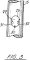
図3は本発明の装置の好ましい実施態様の別の部分断面正面図である。
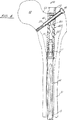
図4は大腿骨方式を示す本発明の装置の好ましい実施態様の正面図である。
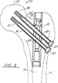
図5はレコン方式を示す本発明の装置の好ましい実施態様の正面図である。
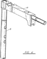
図6はドリルガイドを付けた使用で示す本発明の装置の好ましい実施態様の斜視図である。
図1−5は、一般的に番号10で表される本発明の装置の好ましい具体例を示している。骨髄内固定釘10は、一体型の釘本体又はモジュール式である釘本体11を備える。図1−5でモジュール式釘が示されている。図中、近位端12は、遠位部分13に接続している中央14につながっているテーパー状ソケット16を持つ頭部15の形である。(図4参照)そのようなモジュール式骨髄内固定釘の構造や使用は一般に、ブロス ナーン、ジェームズ、リー、ラッセルを発明者とする1994年7月14日出願の先の米国特許出願番号08/275,806に見られ、ここに引用により本発明の一部とする。
頭部15には隣接する中央部釘部分14とのテーパー固定結合のような、結合を作成するためのソケット16を備える。骨髄内固定釘10は中央縦部貫通孔を備える。貫通孔17(図2)は頭部15の下部に、釘のために縦に伸びる貫通孔である。頭部15は中央縦貫通孔18を備える。好ましい具体例の中においては貫通孔17と18は、共通の中央縦軸20を有する。
頭部15は開口頂部19を与える。貫通孔18が釘10を除くのを助けるため、開口頂部19にてネジ切りされる。更に、開口頂部19はそこへドリルガイド55を取りつけるための場所を提供する(図6参照)。
複数の5つの開口部21−25は、頭部15の壁15Aを通じて伸びている。これら5つの開口部21−25は、組み合わさって骨ネジ40と41を受け入れるための3つの分離した通路を与える。
図1では、開口部23と24は、共通軸26を有する円筒形状の開口部である。開口部25は大きな開口部で(図3参照)、図3に示すように向かい合った突出部31と32を形成する、一対の円筒部29と30からなっている。円筒状部分29と30はそれぞれ中央軸27と28を有している。軸27と28により形成される角度は70度から105度の間が好ましく、85度が望ましい。
広げられた開口部25の円筒状に形作られた部分29と30は、それぞれ開口部21と22と協力する。開口部21は軸28を有する円筒状に形作られた開口部で、開口部25の円筒部分29と一直線上にならんでいる。それゆえ、骨ネジは開口部21と円筒部分29を通じ、軸28に沿って通路に載置できる。(図4参照)同様に、骨ネジは開口部22と開口部25の円筒部分30を通じ、軸27に沿って通路に載置できる。軸26と27はそれぞれ、釘10の中央軸20と、30度から65度の鋭角、好ましくは45度を形成する。
図4と5では、大腿骨の方式(図4)とレコン方式(図5)が、患者の大腿骨51、大腿骨頭52、大腿骨頸部53、骨髄内管54に関しては、図示されている。
図4では、骨ネジ39が、開口部21と開口部25の円筒状に形づくられた部分29とで定義される通路を通じて載置されている。骨ネジ39は、開口部21の内壁33と円筒状部分29の内壁37に適合する外側の壁を有する円筒状に形作られた、非ネジ切りの滑らかな部分42を備える。
図5では、レコン方式が、それぞれ開口部22と23を通じて設置されている骨ネジ40と41で示されている。骨ネジ40は開口部22と開口部25の円筒部分30とで定義される通路を通じて軸27に沿って伸びている。骨ネジ41は開口部23と開口部24で形成される通路を通じ、軸26に沿って伸びている。
骨ネジ40と41の滑らかな非ネジ切り部43と44は、それぞれ内壁34と38又は35と36と係合している。図4と5では、骨ネジ39−41のそれぞれは、ネジ切り部45、46、47を備える。更に、各骨ネジ39−41は拡大された頭部48−50を与える。
次の表は、ここで使用されたり、ここに添付した図形部分中の、部分の番号と説明が列挙してある。
部分一覧表
部分番号 説明
10 骨髄内固定釘
11 釘本体
12 近体端
13 遠位端
14 中央
15 頭部
15A 壁
16 テーパー状ソケット
17 貫通孔
18 貫通孔
19 開口頂部
20 中央縦軸
21 開口部
22 開口部
23 開口部
24 開口部
25 開口部
26 軸
27 軸
28 軸
29 円筒部
30 円筒部
31 突出部
32 突出部
33 内壁
34 内壁
35 内壁
36 内壁
37 内壁
38 内壁
39 骨ネジ
40 骨ネジ
41 骨ネジ
42 非ネジ切り部
43 非ネジ切り部
44 非ネジ切り部
45 ネジ切り部
46 ネジ切り部
47 ネジ切り部
48 頭部
49 頭部
50 頭部
51 大腿骨
52 大腿骨頭
53 大腿骨頸部
54 骨髄内管
55 ドリルガイド
数多くの様々な異なった具体例が、ここに教えられた発明概念の範囲内でなされ、又、法に記述された要求に従ってここに記述された具体例に、多くの改良がなされ得るため、ここの記述は例示的なものであり、限定的意味では解釈されない。The present invention relates generally to devices used to treat femoral fractures, and more particularly to intramedullary fixation rods and nails.
There are various types of devices used to treat femoral fractures. Subtrochanteric and femoral shaft fractures are treated with the help of intramedullary fixation nails, which are inserted into the intramedullary canal of the femur and the fractured femur Fix the part. Angled cross nails or fixation screws are inserted into the proximal end of the femur and intramedullary fixation rod. In some, one or more screws may be inserted through the distal end of the femoral shaft and the intramedullary fixation nail. Standard intramedullary nails have been used successfully to treat fractures in the lower part of the femoral shaft.
Femoral neck, head, or trochanteric fractures have been successfully treated with some compression screw assemblies that typically have a compression plate with a barrel member, lag screw and compression screw. . The compression plate is fixed to the outside of the femur, and the tubular member is inserted into a hole that is pre-drilled in the direction of the femoral head. A lag screw having a threaded portion and a smooth portion is inserted through the tubular member such that it extends across the break and into the femoral head. The threaded portion engages the femoral head. The compression screw connects the lag screw to the plate. By adjusting the tension of the compression screw, the compression (reduction) of the fracture can be adjusted. The smooth part of the lag screw needs to be able to slide freely in the tubular member so that the compression screw can be adjusted. Several patents granted to Brumfield and the assignee of this application extend laterally and diagonally, including US Pat. Nos. 4,827,917, 5,167,663, and 5,312,406. The present invention relates to an intramedullary fixation nail prosthesis having a bone screw.
The Russell-Taylor interlocking nail system manufactured by Smith & Nephew Richards, Inc., Memphis, Tennessee, includes an intramedullary fixation rod with two pairs of holes through its proximal end. The axis of the hole pair intersects to provide a right or left direction for inserting one fixing screw. The screw is designed to pass from a larger trochanter to a smaller trochanter. Since the second pair of holes weakens the nail when loaded in the direction of the femoral head, there is not enough mechanical support to use a fixation screw in that direction. Furthermore, the fixing screw is a screw that is entirely threaded and does not allow the screw to slide relative to the intramedullary fixing rod.
A compression screw assembly is shown in the following patent. US Pat. No. 4,432,358 to Fixel, US Pat. No. 3,374,786 to Callender jr., US Pat. No. 2,702,543 to Pugh et al., US Pat. No. 4,530,355 to Griggs. Blosser, U.S. Pat. No. 3,094,120, and Wagner, U.S. Pat. No. 3,842,825. The Blosser and Wagner patents describe the use of multiple screws to prevent rotation of the lag screw relative to the compression plate and tubular member. A surgical bone pin that functions like a lag screw and compression screw, but without a compression plate, is known from US Pat. No. 3,103,926 to Cochran et al.
British Patent GB 2,167,775A discloses an intramedullary fixation nail for fixing a long fractured bone. The nail has a head and a tip portion with a shank and a groove with an open end for engaging a bolt previously inserted into the bone across the bone axis to secure the nail to the bone. ing. Mareno patent 4,733,654 discloses an intramedullary fixation nail assembly adapted for internal fixation of a femoral comminuted fracture, which includes a conventional femoral fixation nail and extension, and a nail and its nail This is a combination of a pair of pins connected to the extending portion. The extension is designed to be inserted into the proximal end of the femoral nail and is pre-drilled to accept pins that extend diagonally in the femoral neck. A drill guide that can be inserted into the proximal end of the extension provides a convenient tool for pre-drilling the femur in the right place and at the right angle. The nail itself can also be pre-drilled to accept the pin over a drill guide attached to the bench.
The Chapman patent discloses a modular femoral fixation system used for the treatment of femoral abnormalities resulting from trauma, disease or birth defects. The device consists of at least three interconnectable parts. They are,
1) an elongated, epiphysis / metaphyseal implant,
Angled with 2) an intramedullary fixation rod, and 3) an elongated plate section adapted to be secured to the external cortical wall and a hollow sleeve adapted to extend into the femur It is a side plate. The epiphysis / metaphysis implant can be connected to either an angled side plate or an intramedullary fixation rod. The system also includes an elongated bone plate that can be connected to an angled side plate, one or more other epiphyseal / metaphyseal implants of variable length, another angled side plate, and an elongated bone plate A distal buttress plate that can be connected to and a plurality of bone screws of general design. It is preferred that many or all of these parts of the system are made of an inner elastic titanium-based alloy.
Grosse-Kempf nails manufactured by Howmedica Company in Rutherford, NJ are believed to be one of the earliest intramedullary nail fixation devices introduced to the United States. The Gross-Kempf nail has a threaded hole in the intramedullary fixation rod to accept the connecting screw. Fully threaded cannot slide into this threaded hole and the compression mold found in the compression screw assembly described above cannot be used. Furthermore, the axis of the threaded hole coincides with the line between the greater trochanter and the lesser trochanter and does not coincide with the direction of the femoral neck.
Zickel's US Patent 3,433,220, issued March 18, 1969, is useful for the treatment of fractures occurring in the upper third of the lower trochanter of the femur. A rod and cross screw assembly is disclosed. The Zickel nail is a rigid intramedullary nail with a single proximal tri-flange cross nail inserted in the direction of the femoral head. The intramedullary fixation rod is bent in two planes to resemble the shape of the femur. The hard crossing does not allow insertion beyond the guide rod, and therefore a closed surgical technique cannot be performed, so the Zickel nails cannot be used for femoral comminuted and distal fractures. A rigid tri-flange cross nail is not suitable for the treatment of femoral neck fractures because the cross nail must be secured with a set screw to prevent it from turning back out. Sufficient compression cannot be achieved. As mentioned above, sliding compression screws have been found to be very effective in treating femoral neck fractures.
A commercial Kuntscher Y-nail is a flanged clover-type intramedullary fixation nail that is inserted through the hole of a single femoral neck nail. The rod has a longitudinal slit. Kunchar's device is indicated only for unstable trochanteric fractures. Neither the Kuncher device nor the Zickel device has a distal anchoring means and is not beneficial for treating distal fractures. The femur neck nail of Kuncher's device angled towards the femoral neck is secured by an intramedullary fixation rod. Therefore, Kuncher's Y-nail is not indicated for femoral neck fractures.
A bone screw that allows left and right orientation by means of a “cross” nail hole is shown by Enter US Pat. No. 4,475,545.
In unstable fractures under the trochanter, an implant such as a crotch indirect compression screw plate often failed due to extreme loading. In the case of severe crushing of the femoral shaft, sometimes the existing connection screws do not provide sufficient strength.
The current treatment of femoral neck and shaft fractures is done with two nails (a femoral nail in the case of a shaft fracture) and a recon nail (in a combination of a femoral neck and a shaft fracture). The The femoral nail is provided with a single downwardly sloping screw for proximal fixation. Recon nails are provided with two diagonal screws above.
Femoral nails can be used on the left and right, while recon nails are specific on the left or right side. The upper diagonal screw is difficult to install and is not recommended for treatment of diaphyseal fractures. It may be dangerous if used in this way. Therefore, recon nails are not used in this way. Recon nails are not used to treat the same side of the femoral fracture that is used to fix neck and shaft fractures.
The recon nail can be used as a femoral nail when used on the opposite foot. For example, when the right recon nail is inserted into the left leg, it can function as a left femoral nail, one hole is empty and one screw hole fits a single downward slanting fixation screw To do. However, a single current recon nail cannot treat both fractures of one leg. Therefore, the hospital must prepare many different femoral and recon nails of different sizes at a large cost.
A femoral neck fracture may be found during a nailing operation of a mere femoral shaft fracture. In this case, removal of the femoral nail is not recommended as it may pose a risk to the neck fracture. The cannulated screw is attached to the neck around the nail to fix the fracture, which is a difficult task.
The present invention is used to treat femoral neck and shaft breakage. According to the present invention, an elongated nail body having an upper end portion, a lower end portion and a central longitudinal through hole, a hollow through hole communicating with the central longitudinal through hole and an axis coinciding with the central longitudinal axis of the nail body, and the hollow through hole thereof A head at the upper end having a cylindrical wall surrounding the hole, the wall having a first and second plurality of openings separated from each other by about 180 degrees, wherein the first plurality of openings comprises: Two substantially parallel lower openings and a third opening having a central axis that forms an angle with respect to the axis of each of the two lower openings, the second plurality of openings being two A patient comprising an opening, one of which is substantially aligned with the axis of one of the parallel openings of the first plurality of openings, the other comprising two intersecting cylindrical through-holes An intramedullary fixation nail graft for use in repairing a femur is provided.
The present invention provides an improved intramedullary fixation nail having three base fixation screw passages, two upwardly inclined passages and one downwardly inclined passage. The nail of the present invention will reduce the recon and femur nail inventory required to commonly fix the fractures that have occurred.
The pair of intramedullary fixation nails of the present invention could be replaced by a femoral nail and two recon nails, reducing inventory by 33%. The surgeon will also be able to change the nail femur system to the recon system during surgery without reducing the risk of metastatic cervical fractures and reduce operating time. The equipment required for the intramedullary fixation nail of the present invention will be less than that required for the femur and recon nail and will reduce the complexity of the operating room supply room.
The present invention provides an improved intramedullary nail implant for use in repairing a patient's femur. The device of the present invention may be a unitary nail or a modular nail consisting of a connectable upper and lower ends, a nail body having a lower end and a central longitudinal through hole. Tapered or morse taper connections can be used between the portions to connect end to end.
The upper end of the nail body has an enlarged head with a hollow through hole that communicates with the central longitudinal through hole and has an axis that coincides with the central longitudinal axis of the nail body.
The proximal portion has a cylindrical wall that surrounds the hollow through hole and provides a wall thickness that is greater than the wall thickness of the central and lower end portions of the nail body.
The proximal wall has five openings therethrough, three of which form the first group and two form the second group, which groups are approximately 180 degrees apart from each other. It is placed in the position.
The first group of openings comprises two generally parallel lower openings and a third upper opening having a central axis that is angled with the respective axes of the two lower openings. . The second group of openings has two openings, one of which is generally aligned with one axis of the parallel openings of the first group of openings. The other largest opening consists of two intersecting cylindrical through holes.
Accordingly, in another embodiment of the present invention, an elongate nail body having an upper end portion, a central portion, a lower end portion and a central longitudinal through hole is provided, and the upper end portion is disposed on the central longitudinal through hole and the central longitudinal axis of the nail body. An enlarged head having a hollow through hole communicating with a matching shaft, having a wall thickness greater than the wall thickness of the center and lower end of the nail body, and having a cylindrical wall surrounding the hollow through hole; And the wall has five through-openings consisting of three openings of the first group and two openings of the second group, each group being arranged 180 degrees apart from each other, the openings of the first group The portion comprises two substantially parallel lower openings and a third upper opening having a central axis that is at an angle with respect to the axis of each of the two lower openings, the second group of openings being It consists of two openings, one of which is parallel to the first group of openings. An intramedullary fixation nail implant used to repair a patient's femur, approximately aligned with one axis of the mouth and the other being the largest of all the openings and consisting of two intersecting cylindrical openings A tissue piece is provided.
In yet another embodiment of the present invention, an elongated nail body having an upper end, a lower end and a central longitudinal through hole, and a hollow penetration communicating with the central longitudinal through hole and an axis coinciding with the central longitudinal axis of the nail body. A top wall having a cylindrical wall surrounding the hollow through hole and having an enlarged upper end, the wall having first and second through openings that are approximately 180 degrees apart from each other. And the first plurality of openings comprises two substantially parallel lower openings and a third opening having a central axis that forms an angle with respect to the axis of each of the two lower openings, The second plurality of openings comprises two openings, one of which is substantially aligned with one axis of the parallel openings of the first plurality of openings and the other is two An intramedullary fixation nail graft for use in repairing a patient's femur is provided that consists of intersecting cylindrical through-holes.
For a further understanding of the nature and objects of the invention, reference should be made to the detailed description taken in conjunction with the accompanying drawings. In the accompanying drawings, like reference numerals designate like parts. In the attached drawings,
FIG. 1 is a partial cross-sectional front view of a preferred embodiment of the apparatus of the present invention.
FIG. 2 is a partial front view of a preferred embodiment of the apparatus of the present invention.
FIG. 3 is another partial cross-sectional front view of a preferred embodiment of the apparatus of the present invention.
FIG. 4 is a front view of a preferred embodiment of the device of the present invention showing the femoral system.
FIG. 5 is a front view of a preferred embodiment of the apparatus of the present invention showing a recon system.
FIG. 6 is a perspective view of a preferred embodiment of the apparatus of the present invention shown in use with a drill guide.
1-5 show a preferred embodiment of the device of the present invention, generally designated by the numeral 10. The intramedullary fixation nail 10 includes an integral nail body or a nail body 11 that is modular. A modular nail is shown in FIGS. 1-5. In the figure, the proximal end 12 is in the form of a
The
The
The plurality of five openings 21-25 extend through the
In FIG. 1, the openings 23 and 24 are cylindrical openings having a
The cylindrically shaped
4 and 5, the femur system (FIG. 4) and the recon system (FIG. 5) are illustrated with respect to the patient's
In FIG. 4, the bone screw 39 is placed through a passage defined by the
In FIG. 5, the recon system is shown with
Smooth
The following table lists part numbers and descriptions in the graphic parts used or attached here.
Part list part number Description
10 Intramedullary fixation nails
11 Nail body
12 near edge
13 Distal end
14 center
15 heads
15A wall
16 Tapered socket
17 Through hole
18 Through hole
19 Opening top
20 Center vertical axis
21 opening
22 opening
23 opening
24 opening
25 opening
26 axes
27 axes
28 axes
29 Cylindrical part
30 Cylindrical part
31 Protrusion
32 Protrusion
33 inner wall
34 Inner wall
35 inner wall
36 inner wall
37 inner wall
38 inner wall
39 Bone screw
40 bone screws
41 bone screw
42 Non-threaded part
43 Non-threaded part
44 Non-threaded part
45 Threaded part
46 Threaded part
47 Threaded part
48 heads
49 head
50 heads
51 Femur
52 femoral head
53 Femoral neck
54 Intramedullary canal
55 Drill Guide Many different embodiments are possible within the scope of the inventive concept taught herein, and many improvements may be made to the embodiments described herein in accordance with the requirements set forth in the law. Thus, the description herein is exemplary and is not to be construed in a limiting sense.
Claims (8)
b)その中央縦孔(17)に連通し釘本体(11)の中央縦軸(20)に一致する軸(20)を有する中央縦孔(18)と、その中央縦孔(18)を囲む円筒状壁(15A)とを有する、上端部(12)における頭部(15)、を備え、
c)壁(15A)が、中央縦孔(18)を挟んで互いに対向 するように配置された第1(21−23)の複数の開口部及び第2(24,25)の複数の開口部を有し、
d)第1(21−23)の複数の開口部は、ほぼ平行な第1(26)及び第2(27)軸を有する第1(23)及び第2(22)下部開口部と、第1(23)及び第2(22)下部開口部の各々の軸(26,27)に対しある角度をなす第3軸(28)を有する第3(21)上部開口部とからなり、
e)第2(24,25)の複数の開口部は、第1(23)及び第2(22)開口部の1方の開口部の軸(26,27)にほぼ整列する軸(26)を有する第4(24)開口部と、2つの交差する円筒孔(29,30)を有する第5開口部(25)、
からなる、
患者の大腿骨の補修に使用する骨髄内固定釘インプラン ト(10)。a) an elongated nail body (11) having an upper end (12), a lower end (13) and a central longitudinal hole (17,18) with a central longitudinal axis (20);
b) a Hisashitate hole (18) in which chromatic axis (20) that matches the central longitudinal axis (20) of the communicating nail body to the central longitudinal bore (17) (11), among which Hisashitate bore (18 A head ( 15 ) at the upper end (12), with a cylindrical wall (15A) surrounding
c) the wall (15A) is a plurality of openings and a plurality of openings of the second (24, 25) of the first (21-23) which are arranged so as to face each other across a central vertical hole (18) Have
d) a plurality of first (21-23) openings comprising first (23) and second (22) lower openings having first (26) and second (27) axes substantially parallel; A third (21) upper opening having a third axis (28) that forms an angle with respect to each axis (26, 27) of each of the first (23) and second (22) lower openings;
e) A plurality of second (24,25) openings are axes (26) that are substantially aligned with the axes (26,27) of one of the first (23) and second (22) openings. A fourth (24) opening having a fifth opening (25) having two intersecting cylindrical holes (29, 30);
Consist of,
Intramedullary locking nail-in plan that you want to use in the repair of the patient's femur (10).
b)上端部(12)は、その中央縦孔(17)に連通し釘本体(11)の中央縦軸(20)に一致する軸を有する中央縦孔(18)と、釘本体(11)の中央部(14)及び下端部(13)の壁厚より大きい壁厚で中央縦孔(18)を囲む円筒状壁(15A)とを有する、拡大された頭部(15)を備え、
c)壁(15A)が、第1グループの3つの開口部(21−23)と第2グループの2つの開口部(24,25)からなる5つの貫通開口部(21−25)を有し、両グループは中央縦 孔(18)を挟んで互いに対向するように配置され、
d)第1グループの開口部(21−23)は、第1(23)及び第2(22)下部開口部と、ほぼ平行な第1(26)及び第2(27)軸と、第1(23)及び第2(22)下部開口部の各々の軸に対しある角度をなす第3軸(28)を有する第3(21)上部開口部とからなり、
e)第2グループの開口部(24,25)は、第1(23)及び第2(22)開口部の一方の軸(26,27)にほぼ整列する軸(26)を有する第4(24)開口部と、すべての開口部の中で最も大きく2つの交差する円筒状貫通孔(28,30)を備える第5開口部(25)を備えてなる、
患者の大腿骨の補修に使用する骨髄内固定釘インプラン ト(10)。a) An elongated nail body (11) provided with an upper end (12), a central part (14), a lower end (13), and a central longitudinal hole ( 17, 18) having a central longitudinal axis (20) Prepared,
b) an upper end (12) includes a Hisashitate hole (18) in which have the axis coincident to a central longitudinal axis (20) of the nail body communicating with the central longitudinal bore (17) (11), nail body ( and a cylindrical wall surrounding the medium Hisashitate hole (18) (15A) in the wall thickness greater than the wall thickness of the central portion (14) and lower ends (13) of 11), enlarged head (15) Prepared,
c) The wall (15A) has five through openings (21-25) consisting of three openings (21-23) in the first group and two openings (24, 25) in the second group. , both groups across the central longitudinal bore (18) is arranged so as to face each other,
d) The first group of openings (21-23) includes first (23) and second (22) lower openings, first (26) and second (27) axes substantially parallel, and first A third (21) upper opening having a third axis (28) that forms an angle with respect to each axis of the (23) and second (22) lower openings,
e) The second group of openings (24, 25) has a fourth (26) axis (26) that is substantially aligned with one of the first (23) and second (22) opening axes (26, 27). 24) comprising an opening and a fifth opening (25) comprising the largest two intersecting cylindrical through-holes (28, 30) among all openings;
Intramedullary locking nail-in plan that you want to use in the repair of the patient's femur (10).
b)その中央縦孔(17)と釘本体(11)の中央縦軸(20)に一致する軸を有する中央縦孔(18)と、その中央 縦孔(18)を囲む円筒状壁(15A)とを有する、上端部(12)において拡大する頭部(15)、を備え、
c)壁(15A)が、中央縦孔(18)を挟んで互いに対向 する第1(21−23)及び第2(24,25)の複数の貫通開口部を有し、
d)第1の複数(21−23)の開口部は、ほぼ平行な第1(26)及び第2(27)軸を有する第1(23)及び第2(22)下部開口部と、第1(23)及び第2(22)下部開口部の各々の軸(26,27)に対しある角度をなす第3軸(28)を有する第3(21)上部開口部とからなり、
e)第2(24,25)の複数の開口部は、第1(23)及び第2(22)開口部の一方の軸にほぼ整列する第4(24)開口部と、2つの交差する円筒状貫通孔を有する第5開口部(25)を備えてなる、患者の大腿骨の補修に使用する骨髄内固定釘インプラント(10)。a) an elongated nail body (11) having an upper end (12), a lower end (13) and a central longitudinal hole ( 17, 18) with a central longitudinal axis (20);
b) a cylindrical wall surrounding the Hisashitate hole (18) in having an axis coincident to a central longitudinal axis (20) of the central longitudinal bore (17) and the nail body (11), the inside central longitudinal bore (18) A head (15) that extends at the upper end (12),
c) the wall (15A) has a first (21-23) and a plurality of through openings of the second (24, 25) across the central vertical hole (18) facing each other,
d) the first plurality (21-23) of openings are first (23) and second (22) lower openings having first (26) and second (27) axes substantially parallel; A third (21) upper opening having a third axis (28) that forms an angle with respect to each axis (26, 27) of each of the first (23) and second (22) lower openings;
e) The second (24,25) openings have two intersections with the fourth (24) opening that is substantially aligned with one axis of the first (23) and second (22) openings. An intramedullary fixation nail implant (10) for use in repairing a patient's femur comprising a fifth opening (25) having a cylindrical through hole.
Applications Claiming Priority (3)
| Application Number | Priority Date | Filing Date | Title |
|---|---|---|---|
| US08/332,343 | 1994-10-31 | ||
| US08/332,343 US5549610A (en) | 1994-10-31 | 1994-10-31 | Femoral intramedullary nail |
| PCT/US1995/013757 WO1996013220A1 (en) | 1994-10-31 | 1995-10-25 | Femoral intramedullary nail |
Publications (2)
| Publication Number | Publication Date |
|---|---|
| JP2000513593A JP2000513593A (en) | 2000-10-17 |
| JP3636470B2 true JP3636470B2 (en) | 2005-04-06 |
Family
ID=23297805
Family Applications (1)
| Application Number | Title | Priority Date | Filing Date |
|---|---|---|---|
| JP51470796A Expired - Lifetime JP3636470B2 (en) | 1994-10-31 | 1995-10-25 | Femoral intramedullary fixation nail |
Country Status (11)
| Country | Link |
|---|---|
| US (1) | US5549610A (en) |
| EP (1) | EP0793451B1 (en) |
| JP (1) | JP3636470B2 (en) |
| AT (1) | ATE221755T1 (en) |
| AU (1) | AU689982B2 (en) |
| CA (1) | CA2204035A1 (en) |
| DE (1) | DE69527723T2 (en) |
| DK (1) | DK0793451T3 (en) |
| ES (1) | ES2180662T3 (en) |
| PT (1) | PT793451E (en) |
| WO (1) | WO1996013220A1 (en) |
Families Citing this family (162)
| Publication number | Priority date | Publication date | Assignee | Title |
|---|---|---|---|---|
| GB9411693D0 (en) * | 1994-06-10 | 1994-08-03 | Matthews Michael G | Surgical intramedullary nail for stabilisation of condylar and supracondylar fractures |
| DE19619093B4 (en) * | 1996-05-06 | 2004-02-26 | Aap Implantate Ag | Intramedullary nail system for fracture healing or bone extension |
| US6648890B2 (en) | 1996-11-12 | 2003-11-18 | Triage Medical, Inc. | Bone fixation system with radially extendable anchor |
| US6632224B2 (en) | 1996-11-12 | 2003-10-14 | Triage Medical, Inc. | Bone fixation system |
| US20050143734A1 (en) * | 1996-11-12 | 2005-06-30 | Cachia Victor V. | Bone fixation system with radially extendable anchor |
| DE29620327U1 (en) * | 1996-11-22 | 1998-03-26 | Howmedica Gmbh | Locking nail with adjustable openings for locking screws |
| EP1342453B1 (en) * | 1997-03-19 | 2005-08-24 | Stryker Trauma GmbH | Modular intramedullary nail |
| US6010506A (en) * | 1998-09-14 | 2000-01-04 | Smith & Nephew, Inc. | Intramedullary nail hybrid bow |
| US6120504A (en) * | 1998-12-10 | 2000-09-19 | Biomet Inc. | Intramedullary nail having dual distal bore formation |
| US6221074B1 (en) * | 1999-06-10 | 2001-04-24 | Orthodyne, Inc. | Femoral intramedullary rod system |
| US7018380B2 (en) | 1999-06-10 | 2006-03-28 | Cole J Dean | Femoral intramedullary rod system |
| US6926719B2 (en) | 1999-10-21 | 2005-08-09 | Gary W. Sohngen | Modular intramedullary nail |
| ES2214071T3 (en) * | 1999-12-03 | 2004-09-01 | Synthes Ag Chur | INTRAMEDULAR KEY. |
| US6579293B1 (en) * | 2000-08-02 | 2003-06-17 | Rama E. Chandran | Intramedullary rod with interlocking oblique screw for tibio-calcaneal arthrodesis |
| US6527775B1 (en) | 2000-09-22 | 2003-03-04 | Piper Medical, Inc. | Intramedullary interlocking fixation device for the distal radius |
| US6887243B2 (en) | 2001-03-30 | 2005-05-03 | Triage Medical, Inc. | Method and apparatus for bone fixation with secondary compression |
| US6511481B2 (en) * | 2001-03-30 | 2003-01-28 | Triage Medical, Inc. | Method and apparatus for fixation of proximal femoral fractures |
| US6652528B2 (en) | 2001-07-17 | 2003-11-25 | Biomet, Inc. | Intramedullary nail with modular sleeve |
| US6685706B2 (en) | 2001-11-19 | 2004-02-03 | Triage Medical, Inc. | Proximal anchors for bone fixation system |
| US6793678B2 (en) | 2002-06-27 | 2004-09-21 | Depuy Acromed, Inc. | Prosthetic intervertebral motion disc having dampening |
| US7824429B2 (en) | 2002-07-19 | 2010-11-02 | Interventional Spine, Inc. | Method and apparatus for spinal fixation |
| EP1528895A1 (en) | 2002-08-10 | 2005-05-11 | H. Simon William | Method and apparatus for repairing the mid-food region via an intermedullary nail |
| DE20213166U1 (en) * | 2002-08-28 | 2004-01-08 | Stryker Trauma Gmbh | humeral |
| AU2002328245A1 (en) * | 2002-10-03 | 2004-04-23 | Synthes Ag Chur | Device for bone fixation |
| DE10246386B4 (en) * | 2002-10-04 | 2008-08-07 | Biedermann Motech Gmbh | Bone screw, bone fixation device and retaining element |
| US7070601B2 (en) | 2003-01-16 | 2006-07-04 | Triage Medical, Inc. | Locking plate for bone anchors |
| JP4579697B2 (en) * | 2003-03-07 | 2010-11-10 | ジンテーズ ゲゼルシャフト ミト ベシュレンクテル ハフツング | Set screw for intramedullary nail |
| US7185015B2 (en) | 2003-03-14 | 2007-02-27 | Websense, Inc. | System and method of monitoring and controlling application files |
| US7529754B2 (en) | 2003-03-14 | 2009-05-05 | Websense, Inc. | System and method of monitoring and controlling application files |
| WO2004082494A1 (en) * | 2003-03-21 | 2004-09-30 | Synthes Ag Chur | Intramedullary nail |
| WO2004098453A2 (en) * | 2003-05-06 | 2004-11-18 | Triage Medical, Inc. | Proximal anchors for bone fixation system |
| WO2004110290A1 (en) * | 2003-06-12 | 2004-12-23 | Synthes Ag Chur | Surgical nail |
| CA2531541C (en) * | 2003-06-12 | 2011-05-10 | Synthes (U.S.A.) | Surgical nail |
| DE50311031D1 (en) * | 2003-07-30 | 2009-02-12 | Synthes Gmbh | SURGICAL NAIL |
| WO2005020830A1 (en) * | 2003-08-29 | 2005-03-10 | Synthes Gmbh | Intramedullary nail |
| US20050055024A1 (en) * | 2003-09-08 | 2005-03-10 | James Anthony H. | Orthopaedic implant and screw assembly |
| NZ546545A (en) * | 2003-10-21 | 2008-11-28 | Synthes Gmbh | Intramedullary nail |
| AU2004294998B2 (en) | 2003-12-01 | 2011-03-24 | Smith & Nephew, Inc. | Humeral nail with insert for fixing a screw |
| US8092454B2 (en) * | 2004-03-11 | 2012-01-10 | Sohngen Gary W | Fixation instrument for treating a bone fracture |
| US7771428B2 (en) * | 2004-06-11 | 2010-08-10 | Synthes Usa, Llc | Intramedullary rod with spiraling flutes |
| AU2004320725A1 (en) * | 2004-06-22 | 2005-12-29 | Synthes Gmbh | Intramedullary nail |
| CA2571672C (en) * | 2004-06-24 | 2012-08-28 | Synthes (U.S.A.) | Intramedullary nail |
| ATE504251T1 (en) * | 2004-06-30 | 2011-04-15 | Synthes Gmbh | SURGICAL NAIL |
| US7955357B2 (en) | 2004-07-02 | 2011-06-07 | Ellipse Technologies, Inc. | Expandable rod system to treat scoliosis and method of using the same |
| US7588577B2 (en) | 2004-07-15 | 2009-09-15 | Wright Medical Technology, Inc. | Guide assembly for intramedullary fixation and method of using the same |
| US20060015101A1 (en) | 2004-07-15 | 2006-01-19 | Wright Medical Technology, Inc. | Intramedullary fixation assembly and devices and methods for installing the same |
| US20060089647A1 (en) * | 2004-08-20 | 2006-04-27 | Culbert Brad S | Method and apparatus for delivering an agent |
| DK1639953T3 (en) * | 2004-09-27 | 2008-09-29 | Orthofix Srl | Endomedullary stitch for the treatment of proximal femur fractures |
| KR101230768B1 (en) * | 2004-10-14 | 2013-02-06 | 신세스 게엠바하 | Intramedullary pin for insertion in medullary cavity of femur |
| US7604657B2 (en) * | 2005-09-19 | 2009-10-20 | Depuy Products, Inc. | Bone fixation plate with complex suture anchor locations |
| US8394130B2 (en) | 2005-03-17 | 2013-03-12 | Biomet C.V. | Modular fracture fixation system |
| DE102005005637A1 (en) * | 2005-02-05 | 2006-08-17 | Dieter Marquardt Medizintechnik Gmbh | Femoral nail for provision of thigh and neck fracture, has thigh head-screw connected with thigh head, trochanter-screw inserted into additional cross hole and connected with trochanter major and boreholes to position screws |
| US7410488B2 (en) | 2005-02-18 | 2008-08-12 | Smith & Nephew, Inc. | Hindfoot nail |
| EP1850763B1 (en) * | 2005-02-22 | 2016-09-07 | Smith & Nephew, Inc. | Instrument for targeting blocking screws |
| US7232442B2 (en) | 2005-02-22 | 2007-06-19 | Advanced Orthopaedic Solutions | Humeral nail |
| US9060820B2 (en) | 2005-05-18 | 2015-06-23 | Sonoma Orthopedic Products, Inc. | Segmented intramedullary fracture fixation devices and methods |
| WO2006124764A1 (en) | 2005-05-18 | 2006-11-23 | Sonoma Orthopedic Products, Inc. | Minimally invasive actuable bone fixation devices, systems and methods of use |
| US8961516B2 (en) | 2005-05-18 | 2015-02-24 | Sonoma Orthopedic Products, Inc. | Straight intramedullary fracture fixation devices and methods |
| US20070123874A1 (en) * | 2005-10-31 | 2007-05-31 | Czartoski Timothy J | Multiple purpose nail with oblique openings |
| US20070123873A1 (en) | 2005-10-31 | 2007-05-31 | Czartoski Timothy J | Intramedullary nail with oblique openings |
| US20070123875A1 (en) * | 2005-10-31 | 2007-05-31 | Czartoski Timothy J | Intramedullary nail |
| US20070123876A1 (en) * | 2005-10-31 | 2007-05-31 | Czartoski Timothy J | Multiple purpose nail, nail assembly and associated method |
| US8453243B2 (en) | 2005-12-28 | 2013-05-28 | Websense, Inc. | Real time lockdown |
| US20070233103A1 (en) * | 2006-03-31 | 2007-10-04 | Metzinger Anthony J | Intramedullary nail, intramedullary nail assembly and method |
| US20070233104A1 (en) * | 2006-03-31 | 2007-10-04 | Metzinger Anthony J | Intramedullary nail implant assembly, kit and method |
| US20070233100A1 (en) * | 2006-03-31 | 2007-10-04 | Metzinger Anthony J | Variable angle intramedullary nail |
| CA2651587C (en) * | 2006-05-09 | 2016-03-22 | Synthes (U.S.A.) | Nail system and method for an olecranon osteotomy |
| US10687869B2 (en) * | 2006-07-05 | 2020-06-23 | Advanced Orthopaedic Solutions, Inc. | Trochanteric nail with locking opening |
| US7862502B2 (en) | 2006-10-20 | 2011-01-04 | Ellipse Technologies, Inc. | Method and apparatus for adjusting a gastrointestinal restriction device |
| CA2670263A1 (en) | 2006-11-22 | 2008-05-29 | Sonoma Orthopedic Products, Inc. | Fracture fixation device, tools and methods |
| US8105382B2 (en) | 2006-12-07 | 2012-01-31 | Interventional Spine, Inc. | Intervertebral implant |
| US9320551B2 (en) | 2007-01-26 | 2016-04-26 | Biomet Manufacturing, Llc | Lockable intramedullary fixation device |
| US8303590B2 (en) * | 2007-01-26 | 2012-11-06 | Ebi, Llc | Lockable intramedullary fixation device |
| US9308031B2 (en) | 2007-01-26 | 2016-04-12 | Biomet Manufacturing, Llc | Lockable intramedullary fixation device |
| US8430879B2 (en) | 2007-03-22 | 2013-04-30 | Sonoma Orthopedic Products, Inc. | Segmented intramedullary structure |
| US8784430B2 (en) * | 2007-04-26 | 2014-07-22 | Zimmer, Inc. | Nail cap cannula |
| US9597129B2 (en) * | 2007-05-25 | 2017-03-21 | Zimmer Gmbh | Reinforced intramedullary nail |
| US7998176B2 (en) | 2007-06-08 | 2011-08-16 | Interventional Spine, Inc. | Method and apparatus for spinal stabilization |
| US8900307B2 (en) | 2007-06-26 | 2014-12-02 | DePuy Synthes Products, LLC | Highly lordosed fusion cage |
| EP3069672B1 (en) | 2007-10-16 | 2019-11-13 | Biomet Manufacturing, LLC | Apparatus for orthopedic fixation |
| US20090112263A1 (en) | 2007-10-30 | 2009-04-30 | Scott Pool | Skeletal manipulation system |
| US8771283B2 (en) | 2007-12-17 | 2014-07-08 | Wright Medical Technology, Inc. | Guide assembly for intramedullary fixation and method of using the same |
| EP2237748B1 (en) | 2008-01-17 | 2012-09-05 | Synthes GmbH | An expandable intervertebral implant |
| US11202707B2 (en) | 2008-03-25 | 2021-12-21 | Nuvasive Specialized Orthopedics, Inc. | Adjustable implant system |
| CA2720580A1 (en) | 2008-04-05 | 2009-10-08 | Synthes Usa, Llc | Expandable intervertebral implant |
| WO2009152273A1 (en) | 2008-06-10 | 2009-12-17 | Sonoma Orthopedic Products, Inc. | Fracture fixation device, tools and methods |
| CA2738478A1 (en) | 2008-09-26 | 2010-04-01 | Sonoma Orthopedic Products, Inc. | Bone fixation device, tools and methods |
| US11241257B2 (en) | 2008-10-13 | 2022-02-08 | Nuvasive Specialized Orthopedics, Inc. | Spinal distraction system |
| WO2010043380A1 (en) | 2008-10-15 | 2010-04-22 | Zimmer Gmbh | Intramedullary nail |
| US8382756B2 (en) | 2008-11-10 | 2013-02-26 | Ellipse Technologies, Inc. | External adjustment device for distraction device |
| US8197490B2 (en) | 2009-02-23 | 2012-06-12 | Ellipse Technologies, Inc. | Non-invasive adjustable distraction system |
| US9526620B2 (en) | 2009-03-30 | 2016-12-27 | DePuy Synthes Products, Inc. | Zero profile spinal fusion cage |
| US9622792B2 (en) | 2009-04-29 | 2017-04-18 | Nuvasive Specialized Orthopedics, Inc. | Interspinous process device and method |
| CA2765376C (en) * | 2009-06-30 | 2017-06-06 | Smith & Nephew, Inc. | Orthopaedic implant and fastener assembly |
| KR101710741B1 (en) | 2009-09-04 | 2017-02-27 | 누베이시브 스페셜라이즈드 오소페딕스, 인크. | Bone growth device and method |
| US9393129B2 (en) | 2009-12-10 | 2016-07-19 | DePuy Synthes Products, Inc. | Bellows-like expandable interbody fusion cage |
| JP5497194B2 (en) | 2009-12-11 | 2014-05-21 | スモール・ボーン・イノベーションズ・インコーポレーテッド | Ankle fusion device, instrument, and method |
| US8540714B2 (en) * | 2010-05-11 | 2013-09-24 | Orthopediatrics Corp. | Pediatric intramedullary nail |
| DE102010023640B4 (en) * | 2010-06-14 | 2015-04-09 | Bernhard Clasbrummel | Nail screw system for angular stable osteosynthesis |
| US9907560B2 (en) | 2010-06-24 | 2018-03-06 | DePuy Synthes Products, Inc. | Flexible vertebral body shavers |
| US8979860B2 (en) | 2010-06-24 | 2015-03-17 | DePuy Synthes Products. LLC | Enhanced cage insertion device |
| AU2011271465B2 (en) | 2010-06-29 | 2015-03-19 | Synthes Gmbh | Distractible intervertebral implant |
| US9248043B2 (en) | 2010-06-30 | 2016-02-02 | Ellipse Technologies, Inc. | External adjustment device for distraction device |
| WO2012021378A2 (en) | 2010-08-09 | 2012-02-16 | Ellipse Technologies, Inc. | Maintenance feature in magnetic implant |
| US9402732B2 (en) | 2010-10-11 | 2016-08-02 | DePuy Synthes Products, Inc. | Expandable interspinous process spacer implant |
| WO2012112396A2 (en) | 2011-02-14 | 2012-08-23 | Ellipse Technologies, Inc. | Device and method for treating fractured bones |
| CN103796602B (en) | 2011-09-16 | 2017-03-29 | 斯泰克欧洲控股一有限责任公司 | Multiaxis lockhole apparatus |
| US10743794B2 (en) | 2011-10-04 | 2020-08-18 | Nuvasive Specialized Orthopedics, Inc. | Devices and methods for non-invasive implant length sensing |
| US9265541B2 (en) * | 2011-10-28 | 2016-02-23 | Stryker Trauma Gmbh | Intramedullary nail locking hole arrangement |
| US10016220B2 (en) | 2011-11-01 | 2018-07-10 | Nuvasive Specialized Orthopedics, Inc. | Adjustable magnetic devices and methods of using same |
| US20130338714A1 (en) | 2012-06-15 | 2013-12-19 | Arvin Chang | Magnetic implants with improved anatomical compatibility |
| US8940052B2 (en) | 2012-07-26 | 2015-01-27 | DePuy Synthes Products, LLC | Expandable implant |
| US20140067069A1 (en) | 2012-08-30 | 2014-03-06 | Interventional Spine, Inc. | Artificial disc |
| US9044281B2 (en) | 2012-10-18 | 2015-06-02 | Ellipse Technologies, Inc. | Intramedullary implants for replacing lost bone |
| EP2722016A1 (en) * | 2012-10-19 | 2014-04-23 | Rapido Med GmbH | Attachment for the proximal end of a bone marrow nail |
| CN104902854B (en) | 2012-10-29 | 2017-10-03 | 诺威适骨科专科公司 | The adjustable apparatus scorching for treating knee endoprosthesis |
| DE102012024687A1 (en) * | 2012-12-18 | 2014-06-18 | Cornelius Bobbert | Lockable intramedullary nail with at least one insert for receiving a locking screw |
| US9522070B2 (en) | 2013-03-07 | 2016-12-20 | Interventional Spine, Inc. | Intervertebral implant |
| US9179938B2 (en) | 2013-03-08 | 2015-11-10 | Ellipse Technologies, Inc. | Distraction devices and method of assembling the same |
| US9522028B2 (en) | 2013-07-03 | 2016-12-20 | Interventional Spine, Inc. | Method and apparatus for sacroiliac joint fixation |
| US10226242B2 (en) | 2013-07-31 | 2019-03-12 | Nuvasive Specialized Orthopedics, Inc. | Noninvasively adjustable suture anchors |
| US9801734B1 (en) | 2013-08-09 | 2017-10-31 | Nuvasive, Inc. | Lordotic expandable interbody implant |
| US10751094B2 (en) | 2013-10-10 | 2020-08-25 | Nuvasive Specialized Orthopedics, Inc. | Adjustable spinal implant |
| US9770278B2 (en) | 2014-01-17 | 2017-09-26 | Arthrex, Inc. | Dual tip guide wire |
| US9839454B2 (en) | 2014-03-21 | 2017-12-12 | Biomet C.V. | Intramedullary device with compound fastener trajectories |
| JP6626458B2 (en) | 2014-04-28 | 2019-12-25 | ニューヴェイジヴ スペシャライズド オーソペディクス,インコーポレイテッド | System for information magnetic feedback in adjustable implants |
| US9814499B2 (en) | 2014-09-30 | 2017-11-14 | Arthrex, Inc. | Intramedullary fracture fixation devices and methods |
| EP3777732A1 (en) | 2014-10-23 | 2021-02-17 | NuVasive Specialized Orthopedics, Inc. | Remotely adjustable interactive bone reshaping implant |
| US10398482B2 (en) | 2014-11-25 | 2019-09-03 | Swemac Innovation Ab | Intramedullary nail |
| JP6847341B2 (en) | 2014-12-26 | 2021-03-24 | ニューベイシブ スペシャライズド オーソペディックス,インコーポレイテッド | Systems and methods for extension |
| US10238427B2 (en) | 2015-02-19 | 2019-03-26 | Nuvasive Specialized Orthopedics, Inc. | Systems and methods for vertebral adjustment |
| US11426290B2 (en) | 2015-03-06 | 2022-08-30 | DePuy Synthes Products, Inc. | Expandable intervertebral implant, system, kit and method |
| EP3884892B1 (en) * | 2015-04-24 | 2023-09-27 | Biomet Manufacturing, LLC | Humeral nail |
| US9913727B2 (en) | 2015-07-02 | 2018-03-13 | Medos International Sarl | Expandable implant |
| WO2017066774A1 (en) | 2015-10-16 | 2017-04-20 | Nuvasive Specialized Orthopedics, Inc. | Adjustable devices for treating arthritis of the knee |
| EP4275631A3 (en) | 2015-12-10 | 2024-02-28 | NuVasive Specialized Orthopedics, Inc. | External adjustment device for distraction device |
| CN113598921A (en) | 2016-01-28 | 2021-11-05 | 诺威适骨科专科公司 | System for bone migration |
| WO2017139548A1 (en) | 2016-02-10 | 2017-08-17 | Nuvasive Specialized Orthopedics, Inc. | Systems and methods for controlling multiple surgical variables |
| EP3474783B1 (en) | 2016-06-28 | 2023-05-03 | Eit Emerging Implant Technologies GmbH | Expandable, angularly adjustable intervertebral cages |
| US11596523B2 (en) | 2016-06-28 | 2023-03-07 | Eit Emerging Implant Technologies Gmbh | Expandable and angularly adjustable articulating intervertebral cages |
| US10492803B2 (en) | 2016-09-22 | 2019-12-03 | Globus Medical, Inc. | Systems and methods for intramedullary nail implantation |
| US10751096B2 (en) | 2016-09-22 | 2020-08-25 | Bala Sundararajan | Systems and methods for intramedullary nail implantation |
| US11045242B2 (en) | 2016-09-22 | 2021-06-29 | Globus Medical, Inc. | Systems and methods for intramedullary nail implantation |
| US11083503B2 (en) | 2016-09-22 | 2021-08-10 | Globus Medical, Inc. | Systems and methods for intramedullary nail implantation |
| US10299847B2 (en) | 2016-09-22 | 2019-05-28 | Globus Medical, Inc. | Systems and methods for intramedullary nail implantation |
| US10537436B2 (en) | 2016-11-01 | 2020-01-21 | DePuy Synthes Products, Inc. | Curved expandable cage |
| US10888433B2 (en) | 2016-12-14 | 2021-01-12 | DePuy Synthes Products, Inc. | Intervertebral implant inserter and related methods |
| US10398563B2 (en) | 2017-05-08 | 2019-09-03 | Medos International Sarl | Expandable cage |
| US11344424B2 (en) | 2017-06-14 | 2022-05-31 | Medos International Sarl | Expandable intervertebral implant and related methods |
| US10940016B2 (en) | 2017-07-05 | 2021-03-09 | Medos International Sarl | Expandable intervertebral fusion cage |
| US11446072B2 (en) | 2017-10-10 | 2022-09-20 | DePuy Synthes Products, Inc. | Self-retaining nail to insertion handle interface |
| EP3694430A1 (en) | 2017-10-11 | 2020-08-19 | Tornier, Inc. | Humeral fixation plate guides |
| KR102153796B1 (en) * | 2018-10-16 | 2020-09-08 | 주식회사 아이키 | Intramedulary lod for bone joint |
| US11446156B2 (en) | 2018-10-25 | 2022-09-20 | Medos International Sarl | Expandable intervertebral implant, inserter instrument, and related methods |
| EP3922039A1 (en) | 2019-02-07 | 2021-12-15 | NuVasive Specialized Orthopedics, Inc. | Ultrasonic communication in medical devices |
| US11589901B2 (en) | 2019-02-08 | 2023-02-28 | Nuvasive Specialized Orthopedics, Inc. | External adjustment device |
| US11633219B2 (en) | 2019-06-26 | 2023-04-25 | Globus Medical, Inc. | Fenestrated pedicle nail |
| US11426286B2 (en) | 2020-03-06 | 2022-08-30 | Eit Emerging Implant Technologies Gmbh | Expandable intervertebral implant |
| US11806054B2 (en) | 2021-02-23 | 2023-11-07 | Nuvasive Specialized Orthopedics, Inc. | Adjustable implant, system and methods |
| US11850160B2 (en) | 2021-03-26 | 2023-12-26 | Medos International Sarl | Expandable lordotic intervertebral fusion cage |
| US11752009B2 (en) | 2021-04-06 | 2023-09-12 | Medos International Sarl | Expandable intervertebral fusion cage |
| US11737787B1 (en) | 2021-05-27 | 2023-08-29 | Nuvasive, Inc. | Bone elongating devices and methods of use |
Family Cites Families (4)
| Publication number | Priority date | Publication date | Assignee | Title |
|---|---|---|---|---|
| US4976258A (en) * | 1983-03-09 | 1990-12-11 | Howmedica International, Inc. | Locking nail |
| US4622959A (en) * | 1985-03-05 | 1986-11-18 | Marcus Randall E | Multi-use femoral intramedullary nail |
| US5167663A (en) * | 1986-12-30 | 1992-12-01 | Smith & Nephew Richards Inc. | Femoral fracture device |
| US5122141A (en) * | 1990-08-30 | 1992-06-16 | Zimmer, Inc. | Modular intramedullary nail |
-
1994
- 1994-10-31 US US08/332,343 patent/US5549610A/en not_active Expired - Lifetime
-
1995
- 1995-10-25 CA CA002204035A patent/CA2204035A1/en not_active Abandoned
- 1995-10-25 ES ES95938891T patent/ES2180662T3/en not_active Expired - Lifetime
- 1995-10-25 AT AT95938891T patent/ATE221755T1/en not_active IP Right Cessation
- 1995-10-25 PT PT95938891T patent/PT793451E/en unknown
- 1995-10-25 AU AU40107/95A patent/AU689982B2/en not_active Expired
- 1995-10-25 DE DE69527723T patent/DE69527723T2/en not_active Expired - Lifetime
- 1995-10-25 EP EP95938891A patent/EP0793451B1/en not_active Expired - Lifetime
- 1995-10-25 DK DK95938891T patent/DK0793451T3/en active
- 1995-10-25 WO PCT/US1995/013757 patent/WO1996013220A1/en active IP Right Grant
- 1995-10-25 JP JP51470796A patent/JP3636470B2/en not_active Expired - Lifetime
Also Published As
| Publication number | Publication date |
|---|---|
| EP0793451B1 (en) | 2002-08-07 |
| DE69527723D1 (en) | 2002-09-12 |
| EP0793451A1 (en) | 1997-09-10 |
| AU689982B2 (en) | 1998-04-09 |
| ATE221755T1 (en) | 2002-08-15 |
| CA2204035A1 (en) | 1996-05-09 |
| DE69527723T2 (en) | 2003-05-15 |
| WO1996013220A1 (en) | 1996-05-09 |
| EP0793451A4 (en) | 1998-08-12 |
| ES2180662T3 (en) | 2003-02-16 |
| JP2000513593A (en) | 2000-10-17 |
| DK0793451T3 (en) | 2002-12-02 |
| AU4010795A (en) | 1996-05-23 |
| US5549610A (en) | 1996-08-27 |
| PT793451E (en) | 2002-12-31 |
Similar Documents
| Publication | Publication Date | Title |
|---|---|---|
| JP3636470B2 (en) | Femoral intramedullary fixation nail | |
| US5167663A (en) | Femoral fracture device | |
| US5312406A (en) | Method of treating an intertrochanteric fracture | |
| US11123118B2 (en) | Periprosthetic bone plates | |
| JP3009232B2 (en) | Hip intramedullary screw | |
| EP0381462B1 (en) | Apparatus for treating a fracture | |
| JP2766641B2 (en) | Kit used to treat femoral disorders | |
| US7976570B2 (en) | Bone plate | |
| US10010355B2 (en) | Intramedullary nail with oblique openings | |
| US6706046B2 (en) | Intramedullary fixation device for metaphyseal long bone fractures and methods of using the same | |
| US5484439A (en) | Modular femur fixation device | |
| US20010034523A1 (en) | Orthopedic implant used to repair intertrochanteric fractures and a method for inserting the same | |
| JP2007125386A (en) | Multipurpose nail, nail assembly, and related method | |
| JP2007125388A (en) | Multipurpose nail having slanting opening | |
| US20080262498A1 (en) | Double locked hip implant | |
| US20240024003A1 (en) | Distal tibial plating system | |
| JP2007125387A (en) | Intramedullary nail | |
| US8758345B2 (en) | Interlocking nail geometry and method of use | |
| EP3398526A1 (en) | Bone fracture plates und systems | |
| Mubark et al. | Locking plate fixation system for intracapsular fracture neck of femur in young patients | |
| US20230338070A1 (en) | Retrograde Nail with Bone Plate | |
| DE4237520C2 (en) | Set screw to fix the femoral epiphysis against dislocation due to softening of the epiphyseal plate |
Legal Events
| Date | Code | Title | Description |
|---|---|---|---|
| A131 | Notification of reasons for refusal |
Free format text: JAPANESE INTERMEDIATE CODE: A131 Effective date: 20040803 |
|
| A521 | Request for written amendment filed |
Free format text: JAPANESE INTERMEDIATE CODE: A523 Effective date: 20041019 |
|
| TRDD | Decision of grant or rejection written | ||
| A01 | Written decision to grant a patent or to grant a registration (utility model) |
Free format text: JAPANESE INTERMEDIATE CODE: A01 Effective date: 20041207 |
|
| A61 | First payment of annual fees (during grant procedure) |
Free format text: JAPANESE INTERMEDIATE CODE: A61 Effective date: 20050105 |
|
| R150 | Certificate of patent or registration of utility model |
Free format text: JAPANESE INTERMEDIATE CODE: R150 |
|
| FPAY | Renewal fee payment (event date is renewal date of database) |
Free format text: PAYMENT UNTIL: 20080114 Year of fee payment: 3 |
|
| FPAY | Renewal fee payment (event date is renewal date of database) |
Free format text: PAYMENT UNTIL: 20090114 Year of fee payment: 4 |
|
| FPAY | Renewal fee payment (event date is renewal date of database) |
Free format text: PAYMENT UNTIL: 20090114 Year of fee payment: 4 |
|
| FPAY | Renewal fee payment (event date is renewal date of database) |
Free format text: PAYMENT UNTIL: 20100114 Year of fee payment: 5 |
|
| FPAY | Renewal fee payment (event date is renewal date of database) |
Free format text: PAYMENT UNTIL: 20110114 Year of fee payment: 6 |
|
| FPAY | Renewal fee payment (event date is renewal date of database) |
Free format text: PAYMENT UNTIL: 20110114 Year of fee payment: 6 |
|
| FPAY | Renewal fee payment (event date is renewal date of database) |
Free format text: PAYMENT UNTIL: 20120114 Year of fee payment: 7 |
|
| FPAY | Renewal fee payment (event date is renewal date of database) |
Free format text: PAYMENT UNTIL: 20130114 Year of fee payment: 8 |
|
| FPAY | Renewal fee payment (event date is renewal date of database) |
Free format text: PAYMENT UNTIL: 20130114 Year of fee payment: 8 |
|
| R250 | Receipt of annual fees |
Free format text: JAPANESE INTERMEDIATE CODE: R250 |
|
| R250 | Receipt of annual fees |
Free format text: JAPANESE INTERMEDIATE CODE: R250 |
|
| EXPY | Cancellation because of completion of term |