JP3628016B2 - Telecommunications configuration - Google Patents
Telecommunications configuration Download PDFInfo
- Publication number
- JP3628016B2 JP3628016B2 JP51886894A JP51886894A JP3628016B2 JP 3628016 B2 JP3628016 B2 JP 3628016B2 JP 51886894 A JP51886894 A JP 51886894A JP 51886894 A JP51886894 A JP 51886894A JP 3628016 B2 JP3628016 B2 JP 3628016B2
- Authority
- JP
- Japan
- Prior art keywords
- station
- configuration
- subscriber
- masfs
- radio
- Prior art date
- Legal status (The legal status is an assumption and is not a legal conclusion. Google has not performed a legal analysis and makes no representation as to the accuracy of the status listed.)
- Expired - Lifetime
Links
Images


Classifications
-
- H—ELECTRICITY
- H04—ELECTRIC COMMUNICATION TECHNIQUE
- H04W—WIRELESS COMMUNICATION NETWORKS
- H04W84/00—Network topologies
- H04W84/02—Hierarchically pre-organised networks, e.g. paging networks, cellular networks, WLAN [Wireless Local Area Network] or WLL [Wireless Local Loop]
- H04W84/10—Small scale networks; Flat hierarchical networks
- H04W84/14—WLL [Wireless Local Loop]; RLL [Radio Local Loop]
-
- H—ELECTRICITY
- H04—ELECTRIC COMMUNICATION TECHNIQUE
- H04B—TRANSMISSION
- H04B7/00—Radio transmission systems, i.e. using radiation field
- H04B7/24—Radio transmission systems, i.e. using radiation field for communication between two or more posts
- H04B7/26—Radio transmission systems, i.e. using radiation field for communication between two or more posts at least one of which is mobile
- H04B7/2603—Arrangements for wireless physical layer control
- H04B7/2606—Arrangements for base station coverage control, e.g. by using relays in tunnels
-
- H—ELECTRICITY
- H04—ELECTRIC COMMUNICATION TECHNIQUE
- H04B—TRANSMISSION
- H04B7/00—Radio transmission systems, i.e. using radiation field
- H04B7/24—Radio transmission systems, i.e. using radiation field for communication between two or more posts
- H04B7/26—Radio transmission systems, i.e. using radiation field for communication between two or more posts at least one of which is mobile
- H04B7/2603—Arrangements for wireless physical layer control
- H04B7/2609—Arrangements for range control, e.g. by using remote antennas
-
- H—ELECTRICITY
- H04—ELECTRIC COMMUNICATION TECHNIQUE
- H04W—WIRELESS COMMUNICATION NETWORKS
- H04W16/00—Network planning, e.g. coverage or traffic planning tools; Network deployment, e.g. resource partitioning or cells structures
- H04W16/24—Cell structures
- H04W16/26—Cell enhancers or enhancement, e.g. for tunnels, building shadow
Abstract
Description
技術分野
本発明は、請求項1の最初の部分で述べた無線通信構成に関する。
現在まで、圧倒的多数の公衆電話加入者との接続および住宅、事務所との接続は配線によりなされている。これは、回路網が例えば衛星等の無線技術により実現されても、回路網の最終部分では大部分配線が使用されること、すなわち大概の自局内接続は配線の形で行われることを意味している。しかしながら、例えば住宅、事務所等のローカルループに対して配線接続を設置することは、時間を消費し相当な回路網コストを伴う。したがって、ローカルループにおける配線に代わるものとして、無線技術の可能性を研究することに関心が高まっている。高速設置が可能でありかつ局部移動性が利点として得られるため、とりわけこれは新しい第2および第3の公衆網オペレータに対する一般的な関心事である。最初の支配的なオペレータに対しては、少なくとも適切な市場に対する関心がある。一般的ではないが単にある国にだけ関連するもう一つの問題点は、これら特定の国々の公衆電話オペレータに対する規制により、PSTN/ISDN(Public Switched Telephone Network/Integrated Service Digital Network)における移動性の提供が妨げられることである。
従来の技術
加入者との無線リンク接続を使用する試みがいくつかなされている。その概念自体は、ローカルループ内無線(Radio in the Local Loop)、略してRLLと呼ばれる。従来の有線接続は、以下では、有線ローカルループ(Wired Local Loop)すなわちWLLと呼ばれる。第1図に、公衆加入者、住宅および事務所との有線ローカルループ、WLL接続および無線ローカルループ、RLL接続を簡単に示す。BSは基地局を表す。
ローカルループ内無線、RLLの概念に関して、これは2つの基本概念、すなわちいわゆるローカルループ内固定無線(Fixed Radio in the Local Loop)、FRLLおよびローカルループ内移動無線(Mobile Radio in the Local Loop)、MRLLに分割することができる。これら2つの概念をそれぞれ第2図および第3図に示す。
第2図はローカルループ内固定無線の概念を示す。この場合、加入者は、自分の電話機4'を接続する電話ソケット6'を一つ以上有している。また、加入者には違いが判らないので、有線ローカルループとした場合に較べて実際上違いは無い。電話機4'は電話ソケット6'に接続され、電話ソケット6'はいわゆる加入者固定局(Subscriber Fixed Station)SFS、2'に接続され、加入者固定局2'はさらに建物等の屋上に配置されたアンテナ7'に接続され、アンテナ7'を介して基地局BS1',1"との無線接続が確立される。短い破線矢印は隣接基地局1'、1"間にほとんど干渉が無いことを示している。現在までのところ、ローカルループ内固定無線、FRLL概念は、非常に限定された範囲でしか実現されていない。無線マイクロ波リンク接続や特別に開発された無線技術は、孤島や遠隔農場等の電話サービスにしか使用されていない。しかしながら、最近になって、公衆有線電話網の容量が一般的に不足している国々で、既存のアナログセルラー技術に基づいたFRLLシステムが設置されつつある。一つの実施例は、パンフレットLZT120217に詳細に記載されたエリクソン無線アクセスAB(Ericsson Radio Access AB)による無線アクセスシステムRAS 1000である。デジタル無線アクセス技術が必要とされるものを達成するのに、一般的な応用では、高品質音声およびISDN(Integrated Services Digital Network)サービスの有効な暗号化を必要とするため、これらのシステムは時間制限市場に向けられている。ローカルループ内固定無線、FRLLの本質的な特徴は、指向性固定屋上アンテナを加入者の建物に設置できるため、周波数および電力に関して経済的な設置が可能となることである。例えば15dBのアンテナ利得により20〜30dBのバック−フロント絶縁が得られ、再使用クラスターサイズは1まで低下し、後記するローカルループ内移動無線、MRLL、に較べて代表的に10倍高い周波数効率が得られる。この周波数効率は、ISDNサービスだけでなく高い音声品質に必要な高いビットレートを得るのに重要である。また、指向性アンテナにより、時間分散による品質低下の危険性も低減される。しかしながら、FRLLの重大な欠点は、顧客が移動性の利点を得られないことである。
移動性はMRLLにより一つの利点として与えられる。しかしながら、この概念にも欠点があり、例えば無線インフラストラクチュアは、非常に周波数効率が低く、距離制限により非常に費用のかかる基地局を設置する必要がある。その理由は、建築材料、地下室、地形、携帯電話機の仮配置等に無関係に家屋のあらゆる部分で完全な無線接続が要求されることである。これを達成するのは非常に困難で費用がかかる。さらに、顧客側ではアンテナ利得は得られず、移動ユニットを高電力ユニットとすることができない。そのため、FRLLに較べて経路損失は容易に40dBも高くなる。D4伝搬モデルに対する40dBの経路損失により、送信電力が同じである場合のFRLL概念に較べて、基地局(BS)は100倍にもなる(本質的に最悪事態距離が10倍小さいため)。さらに、前記したように、国によっては、電話オペレーターは国の特別な規定により移動性を提供することを防止される。さらに、前記制約により、MRLLは、現在までのところ、テスト方式としてしか利用できず、商業的にはまだ実現されていない。これは、ICC'86、トロント、カナダ、1986年6月22日〜25日のD.C.コックス等の文献“ユニバーサル・デジタル→携帯通信:応用研究展望”に詳しく記載されている。
MRLL概念を第3図に略示する。加入者移動局、SMS、5'(携帯電話機)は、無線接続を介して基地局1',1"と直接通信している。図からお判りのように、屋外だけでなく屋内に対しても、直接接続が行われる。長い破線は、基地局間に高いレベルの干渉があることを示している。
もちろん、所望により、市販の標準コードレス電話機を個人的に購入することにより、通常のWLLもしくはFRLLを有する宅内移動性を提供することができる。これを第4図に示す。独立したコードレス固定部(CFP)が加入者ソケット9に接続されている。CFPはコードレス携帯部(CPP)と通信することができる。しかしながら、コードレス電話機は、オペレーターが提供する基本的なローカルループの一部ではなく、単なる特別に許可された内線にすぎない。さらに、2つの独立した無線システムをタンデム接続しなければならないため、費用がかさむだけでなく、音声信号がさらに遅延する。さらに、コードレスホーンがデジタル送信を使用する場合には、デジタル音声符号化/復号化を2度行わなければならない。移動性も制限され、構内および公衆リンクにそれぞれ異なる周波数帯域を必要とする。
発明の要約
本発明の目的は、信頼度が高く、費用がかさまず、周波数効率が高く、同時に移動性を提供する構成により、前記した問題点を解決することである。さらに、この構成は高い音声品質を提供しなければならず、サービス等級、GOS、は有線接続と同じでなければならない。したがって、本発明は、前記したFRLL方式の利点を前記したMRLL方式の利点と結合するものと言うことができる。基地局、BS、と住宅や事務所内もしくはその周りの携帯電話機との間に周波数効率の高い無線接続を提供することが、本発明の一つの目的である。以後単に住宅と呼ぶ住宅や事務所内の携帯電話機間に効率的に低コストのインターホン機能を提供することが、本発明のもう一つの目的である。例えば前記したような国における場合のように、電話オペレーターが移動性を提供することが許可されないような場合に、プライベートなライセンスにより屋内無線接続を登録する可能性を提供することが、本発明のさらにもう一つの目的である。本発明のもう一つの目的は、広範な移動性を提供することである。もう一つの目的は、公衆リンクだけでなく構内リンクに対しても同じ周波数帯域を使用する可能性を与えることである。
これらおよびその他の目的は、請求項1の特徴部に記載された特徴を有する構成により、達成される。
本発明の他の目的および利点は、本発明の以下の説明から明らかとなる。有利な実施例では、例えば分散ダイナミックチャネル分配を利用して、周波数計画が回避される。
本発明により、第2回に示すいわゆる加入者固定局、SFS、2'は、無線交換局を形成する単純な無線多元接続加入者固定局(Multiple Access Subscriber Fixed Station)、MASFS、にグレードアップされる。それにより、独立した加入者局間だけでなく、基地局と住宅内もしくは住宅まわりの携帯加入者移動局との間の無線接続が行われる。本発明によれば、1台の共通トランシーバ(送信機/受信機)を有する無線スイッチが使用されるため、2つの独立したシステムをタンデム接続しなければならない場合に較べて、音声信号の遅延は著しく小さくなる。一実施例では、加入者局は、MASFSだけでなく到達距離内の基地局(BS)にも直接接続することができる。
本発明の一実施例では、いわゆるマルチキャリア時分割多元接続時分割二重化、MC/TDMA/TDD、技術が使用され、そこでは連続もしくは瞬時ダイナミックチャネル分配が使用されている。これについては、エリクソン無線システムABの本発明の発明者であるD.エーカーベルク(Akerberg)の1992年10月19日〜21日に開催されたIEEEのパーソナル、屋内および移動無線通信に関する第3回国際シンポジュームにおける論文“第3世代移動無線システムに有用な新しい無線接続原理”に詳記されている。ここで参照Aと呼ぶこの参照によれば、選定時点において局すなわちスイッチは全住宅の全加入者局に共通する周波数リソースから最善のチャネルを選定することを連続ダイナミックチャネル選定(Continuous Dynamic Channel Selection)、CDCS、が示唆している。このようにして、基地局や個別加入者に対する周波数計画が回避される。
請求項26には、基地と移動局と携帯制御ハンドオフによるダイナミックチャネル分配(DCA)を利用した無線時分割多元接続(TDMA)時分割二重化(TDD)とを具備するシステムに関する特定実施例が開示されている。
ワイヤレス基地局を挿入すれば、このようなセルラーシステムの覆域(カバレージ)および自局内トラフィック容量をさらに拡張することができる。
前記技術に基づくワイヤレスシステムは、多数の移動局にサービスを提供する有線基地局を設置することにより、ある領域を覆域することができる。これらのシステムは、広域屋外応用に対するマクロセルから屋内高密度応用に対するマイクロおよびピコセルまでのさまざまなスケールで存在する。この技術を応用して、パーソナル通信サービス(PCS)に対するワイヤレス通信もしくはローカルループの配線を置換するワイヤレス通信を提供しようとする関心が高まっている。このような応用では、覆域は依然として計画および有線接続の設置の問題点である。そのため、ワイヤレス基地局を付加することにより覆域を拡張することに、関心が寄せられている。このような構成は非常にフレキシブルとなり、効率的な覆域計画を行うことができる。さらに、このような構成により、局所呼を処理する局所移動性およびトラフィック容量が得られる。
この実施例は、例えばデジタル欧州コードレス電気通信標準(DECT)、ETS300175、を参照したDCAおよび携帯制御ハンドオフによるTDMA技術に基づいたシステムの応用に、より詳細に関連している。DECT標準は12の二重化チャネルの10キャリアを有するMC/TDMA/TDD技術により構成され、フレームサイクル時間は10[ms]である。
本実施例により、例えばDECTのようなシステムにおいては、移動局は、TDDフレームが同期化されるため、有線および無線基地局へ同時にアクセスすることができ、そのダウンリンク送信がフレームの同じ半部だけに生じるようにされる。このような一つのシステム内での基地局のこのようなフレーム同期化は、基地局間ローミングおよびハンドオーバーをサポートするのに必要である。
前記実施例により、ワイヤレス基地局は標準有線基地局およびワイヤレス端末と完全にコンパチブルとなるが、さらに、ワイヤレス基地局は有線基地局と同じ要求を満たすことができる。すなわち、ワイヤレス端末は有線および無線基地局間の違いを調べる必要がない。そのため、ワイヤレス基地局は無線システム網の一部とすることができる。また、ワイヤレス基地局はそのTDMAアーキテクチャにより呼の局所切り替えを行うことができ、そのため、ユーザーの点からワイヤレス網の自局内トラフィック容量を追加することができる。
これらおよび他の実施例は従属項に記載されている。
【図面の簡単な説明】
次に、添付図を参照して制約的意味合いのない例に従って本発明の詳細な説明を行い、ここに、
第5図は加入者移動局と基地局とを相互接続する第2の局を示し、
第6a図は12の二重化チャネルからなる時分割多元接続(TDMA)フレームを示し、
第6b図は“制御データ”が規則的にアクセス権アイデンティティ情報を含むスロット上の送信データの例であり、
第7図はさまざまな同時接続に対してさまざまなタイムスロットを使用する一つのTDMA無線機を示し、
第8図はTDMAタイムスロット同期化および無線機を介した情報の流れを示し、
第9図は多元接続加入者固定局(MASFS)相互通信機能を示し、
第10a図は周波数分割二重化による時分割多元接続(TDMA/FDD)に基づいた構成の周波数帯域を示し、
第10b図は第10a図に従ったシステム内の送信および受信スロットのシフトを示し、
第10c図はインターリーブTDMA/TDD方式の概略を示し、
第11図は構内移動性拡張からなる構成を示し、
第12図は基地局間の同期化を示し、
第13図は全体網の同期化の概略を示し、
第14図は基地局(BS)のブロック図を示し、
第15図はMASFSの形式の無線交換機のブロック図を示し、
第16図は加入者移動局(SMS)のブロック図を示し、
第17図はMASFSに接続された付加加入者固定局を示し、
第18図は一つのMASFSに接続された2つの付加加入者固定局の概略を示し、
第19図は第1の固定局から第2の固定局へ移動局がどのようにハンドオフを行うかを示し、
第20図は特定のハンドオフ要求を満たすMASFSのスロット分配の実施例を示す。
発明の詳細な説明
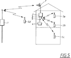
第5図に、基地局(BS)1と低コスト単一無線加入者局の形式の第2の局2と4台の加入者移動局すなわち移動ユニット5a,5b,5c,5d(SMS)とからなる構成を示す。この場合、いわゆる多元接続加入者固定局、MASFS2、である加入者固定局2は、屋上アンテナ7を介して基地局1と接続を行う公衆接続を含んでいる。3台の加入者移動局(SMS)5a〜5cは全て、住宅内もしくはその付近に配置され、屋内アンテナもしくは各加入者移動局5a〜5cのアンテナを介した短距離アンテナ8を介して、前記したように多元接続加入者固定局、MASFS、である加入者固定局2に接続されている。MASFSが屋上アンテナ7を介した公衆接続を屋内アンテナ8を介した加入者移動局5への自局内接続へ切り替えると、移動性が提供される。屋内アンテナを介した2つの自局内接続が相互接続されると、インターホン機能が提供される。一つのTDMAMASFを介してこれがどのように行われるかを第9図を参照して詳細に説明する。また、携帯すなわち加入者移動局5dに、基地局1もしくは一般的にFRLL(Fixed Radio in the Local Loop)基地局網への直接的な付加アクセス権を持たせることもできる。これにより、さらに広範な移動性が得られる。
第2の局2には、さらに、標準(2線)ソケットインターフェイス9(破線が接続を示す)を設けることもできる。第2の局2は一つしか図示されていないが、もちろん2つ以上とすることができる。短距離アンテナ8はいわゆるOMNIアンテナとすることができるが、そうすべき必要性はない。
この概念は、例えばTDMAもしくはTDM無線技術の形式の時分割技術を使用したローカルループ内固定無線システムに基づいている。したがって、第6a図に示すTDMA/TDM(時分割二重化)は、有利な実施例を構成する。第6a図にはいわゆるTDMAフレームが示されており、それは12の二重化チャネルと12の受信スロットと12の送信スロットとを有している。もちろん、異なる数の受信および送信スロットを使用することもできる。一実施例では、この構成がデジタル欧州コードレス電気通信標準、DECT、に適用される。DECT標準は12x12タイムスロットである。フレームサイクル時間TFは、DECT方式に対しては、およそ10[ms]である。参照Aを参照。図において、TおよびRはそれぞれ送信および受信スロットを示し、数字は二重接続のリンクされたスロットを示す。しかしながら、一般的に、TDMAフレームのサイクル時間であるTFの代表的な値は、10msである。
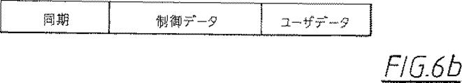
代表的なスロット構造を第6b図に示す。制御データは、アイデンティティおよびアクセス権、同期化基準、利用可能サービス等に関する多重化された情報を規則的に含んでいる。ページングおよび呼設定手順も制御チャネルを介して伝えられる。これは前記した参照Aに詳記されている。代表的な音声コーディックは32kb ADPCMである。これは、各音声呼に対して各フレーム(TF=10ms)中に320ビットを送信および受信しなければならないことを意味する。したがって、ユーザーデータは音声に対して320ビットを含まなければならない。制御データは代表的に64ビットおよび同期化フィールド32ビットを必要とする。ガードスペースを含めると、スロット当たり総ビット数は480となる。フレームが12送信および12受信スロットを有する場合、ビットレートは480×24×100ビット/秒すなわち1152kbit/秒となる。
この実施例では、システムはマルチキャリア、MC、システムである。変調方法に応じて、1.0〜1.8MHzのキャリア間隔で、10のキャリアがある。その一例はDECT標準である。ここに組み入れられている参照Aには、ダイナミックチャネル選定を使用してどのようにチャネルが選定されるかが記載されている。そこで引用されている参照も参照され、それはETSIである。“無線装置およびシステム(RES):デジタル欧州コードレス電気通信(DECT)共通インターフェイス".ETS 300175−1から−9、ETSI,“デジタル欧州コードレス電気通信標準ドキュメント”、ETR 015,ETSI“無線装置およびシステム(RES):デジタル欧州コードレス電気通信(DECT)共通インターフェイスサービスおよび施設要求仕様",ETR 043,およびETSI,“無線装置およびシステム:シミュレーション結果を含む、トラフィック容量および高無線リンク送信品質の維持に影響を及ぼすDECT特徴のデジタル欧州コードレス電気通信(DECT)A案内”、ETR 042である。マルチキャリアTDMA/TDDを使用する実施例については、十分なチャネル(周波数/タイムスロット組み合わせ)を与えるために、BSおよびMSFS2はやはり1台のトランシーバとすることができるが、スロット間のガード帯域ではキャリアを変える可能性があり、それについては参照Aおよび特許第SE−B−466279号に標準基地局概念として詳記されている。このようにして、MSFS2(および携帯加入者局SMS 5)では、1台の無線機により多数のチャネルにアクセスすることができる。
第5図に戻って、第2の局2は、いわゆる多元接続加入者固定局(MSFS)を具備しており、2本の時分割アンテナ7,8に接続されている。屋外アンテナ7すなわち屋上アンテナは、一実施例では、長距離に対する方向性利得(例えば10〜18dB)を有し、最も近い基地局1に向けられているが、短距離用屋内アンテナ8にはアンテナ利得はない。時分割多元接続により、SFS,加入者固定局、2には、さまざまな接続に対してさまざまなタイムスロットを使用して1台の無線機によりいくつかの同時アクティブ接続を行う手段が提供され、それについては、インターホン機能を示す第7図に関して詳細に説明する。そこには、1台のTDMA無線機によりどのようにして低コスト無線スイッチが提供されるかが示されている。すなわち、例えばR4の一つの受信スロット内の第1の加入者局5fから受信したユーザデータを第2の加入者局5gが使用する例えばT7の送信スロットへ単にシフトするだけで、相互接続スイッチが提供される。シフトは、例えば必要な送信スロットT7の時間を合わせるために出力R4が遅延されるデジタル・ファーストイン・ファーストアウト,FIFO,メモリにより、実施される。図において、受信スロットはRで示され、送信スロットはTで示され、いずれも対応する数字が付されている。
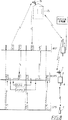
多元接続加入者固定局、MASFS2がスロット対7を使用して屋上アンテナすなわち屋外アンテナ7を介してFRLL BSの基地局1との公衆接続を形成し、同時にスロット対1を使用して屋内アンテナ8を介して加入者移動局すなわち携帯電話機5との接続を形成する様子が、第8図に詳しく示されている。基地局1は、この場合スロット対3を使用する屋上アンテナシステム7aである、長距離すなわち屋外アンテナ7aを備えた例えばもう一つの加入者固定局2a(破線で示す)に接続することもできる。図は、基地局1(BS),加入者固定局2(MASFS)および加入者移動局5(SMS)間のTDMAタイムスロット同期化および無線機を介した情報の流れを示そうとするものである。基地局1は配線により公衆市内交換機に接続されている。第14図に詳しく示すように、公衆交換機からの音声は符号化されかつ基地局1内のTDMA/TDDフレーム内へ多重化される。第15図に詳しく示すように、MASF、2、は、さらに、1台の無線機内でスロット対7を介した構内接続への公衆接続をスロット対1を介した携帯局、SMS、5へ相互接続する。MASFS相互接続は、第7図に関して詳記したいわゆるFIFOメモリを使用して行われる。同期化については後で説明する。
第9図に、加入者固定局すなわちMASFS 2を介した2つの呼の例を示す。一方の呼は基地局1と加入者局すなわち携帯SMS5aとの間の接続を形成し、他方の呼は2つの加入者局5b,5c、特に2つの携帯SMS 5aおよびSMS 5b間の接続を形成する。アンテナ7を介した公衆接続が携帯電話機5aへの構内接続に接続されておれば、移動性が提供されている。2つの構内接続が相互接続されている場合、すなわち加入者局5bおよび加入者局5cへの接続がされている場合には、インターホン機能も提供されている。
第9図に従った実施例では、公衆市内交換機からの配線は基地局1に接続される。
第7図に関して詳細に説明したように、ファーストイン・ファーストアウトメモリすなわちFIFOを介した相互接続機能により音声情報の処理が付加されることはないことを理解されたい。したがって、品質が影響を受けたり低下することはない。音声符号化は基地局1および加入者局5,SMS,だけで行われる。しかしながら、TFmsの2方向遅延の増分に等しい遅延が導入される。ここに、TFはTDMAフレームのサイクルタイムである。これは第7図から引き出され、付加2方向遅延はTA+TB=1/2TF−T1+1/2TF+T1=TFとなる。
FRLL基地局は、通常、一意的な公衆アクセス権アイデンティティを同報している。参照Aを参照されたい。同じ公衆アクセス権を有する加入者固定局、SFS、もしくは加入者移動局、SMS、だけがFRLL BSに固定される。MASFS 2は内部アンテナ8を介して一意的な構内アクセス権キーを送信する。同じ構内アクセス権キーを有する加入者局もしくは加入者移動局、SMS 5、だけがMASFS 2に固定され、受呼および/もしくは発呼の準備が完了する。加入者移動局5は公衆および構内アクセス権キーの両方を備えることができ、それにより、自分の住宅や事務所内およびその付近だけでなくFRLL BSの到達距離内であればどこででも、移動性が与えられる。次に、第8図に戻って、スロットT3,T7,R3,R7が公衆接続を運び、スロットR1,T1が構内接続を運ぶ様子が示されている。
これにより、公衆および構内接続の両方に共通周波数帯域を使用ししかもさまざまな通常隣接する帯域を使用する可能性が得られる。
前記したように、オペレータが移動性を提供することを許可されない場合には、加入者には、標準電話ソケット9eを有する有線内線のある加入者固定局(SFS)を提供することができる。これを第11図に示す。したがって、加入者固定局、SFS、は、認可されたローカルループアプリケーションおよびコードレス構内(非認可)住宅および事務所システムの両方が共通周波数帯域を介して許可される標準的なDECT(参照A)に従って構築されると考えることができる。システム内のさまざまな局に対する周波数計画は、やはり前記参照Aに詳記され例示されているダイナミックチャネル選定により回避される。移動性を要求したい場合、顧客は、メーカーもしくは必要に応じて関連する当局から、構内固定部アクセス権アイデンティティ、屋内アンテナ8eおよびFIFOによるアセンブリカード10eおよび移動加入者局(携帯ハンドセット)5eを入手することができる。一意的な構内アクセス権アイデンティティはMASFS 2eおよび加入者移動局5eへプログラムされる。外部アンテナ7eの公衆リンクには、一意的な公衆アクセス権キーを使用して、構内アクセス権キーしかないSMSが(図示せぬ)基地局BSと通信するのを防止する。したがって、SFSは、第9図に示したように、インターホン機能を含むことができる構内住宅もしくは事務所コードレス電話システムの付加機能を有するMASFSへグレードアップされている。
第6図〜第9図に示す実施例は、低廉で効率的な本発明を実施する一方法を示す時分割二重化による時分割多元接続、TDMA/TDDの使用に関連している。しかしながら、別の実施例では、周波数分割二重化による時分割多元接続すなわちTDMA/FDDを使用することができる。これを第10a図および第10b図に示す。第10a図には、送信帯域TBおよび受信帯域RBを有する周波数軸が示されており、二重化距離dも示されている。第10b図には、送信Tおよび受信Rスロットがそれぞれ示されており、携帯すなわち加入者移動局においてフィルターを二重化する必要性を回避するために、受信機スロット番号は送信スロットに対してシフトされている。この場合、基地局はさまざまな周波数で同時に送受信を行い、そのため、基地局はより費用がかさむようになり、図示するように送信および受信を異なるタイムスロットで実施しないかぎり、通常二重フィルターが必要となる。しかしながら、MASFSは低コストアイテムでなければならないため、受信および送信はすべて異なるスロットで行わなければならず、そのため、接続可能な数は利用可能な送信スロットの半分に制限される。
別の実施例では、第10c図に略示するいわゆるインターリーブTDD方式を使用することができる。
さらに説明を行うために、それぞれ基地局、第2の局(MASFS)および加入者移動局(SMS)のブロック図を示し、各々が二重送信のための12スロット対を有する1台のMC/TDMA/TDD無線機を使用している。
第14図に基地局のブロック図を示す。そこには、市内交換機への有線接続31がある。これは、12の同時呼までのトランクすなわちマルチライン接続である。これらの呼は音声コーディック29によりADPCMフォーマットへ変換される。中央制御及びアプリケーション論理27が着信呼を検出して発信呼を制御し、キャリアとタイムスロットの適切な組み合わせを選定し、マルチプレクサ28を介してさまざまな接続や適切なタイムスロットを併合する。第8図は、基地局が2つの異なる接続に対してどのようにスロット対3および7を選定するかの例を示す。第8図および第9図には、キャリア周波数の選定は示されていない。第14図の基地局は、スロット送受信タイミングを制御するフレーム及びスロット同期化ユニット26を有している。タイミング基準は、内部発生されるかもしくは公衆交換機から有線で送られる同期化信号から引き出される。また、第12図および第13図に示すように、マスター基地局から受信機を介して引き出すこともできる。
中央制御論理27は、T/Rスイッチ23およびアンテナダイバシティが実行される場合のアンテナダイバシティスイッチ22も制御する。アンテナダイバシティが実行されない場合には、スイッチ22は必要ではない。接続が悪い場合、制御論理は最初に他のアンテナ22を試み、これが役に立たない場合には、無線チャネルを変える。
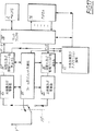
第15図にMASFS 2のブロック図を示す。これは基地局のブロック図とほとんど同じである。主な違いは、第1に指向性である屋外アンテナおよび1本(アンテナダイバシティの場合は2本)の屋内アンテナがあり、第2に4−2線ハイブリッド回路35および標準電話接続のための標準ソケット36で終端された1台の音声コーディック29しかなく、第3に無線交換のためのFIFO 16があることである。DTMFトーン信号およびリング信号の検出と発生は基準ユニット34内で行われる。制御論理27'は、基地局BSと連絡しているタイムスロット用外部アンテナを接続し22'、第8図参照、かつ加入者移動局、SMS、と連絡しているタイムスロット用内部アンテナを接続する。第8図では、スロット番号7は基地局BSとMASFS間の接続用に選定されている。MASFS受信機24'(第15図)は送信T7に固定されている。第8図。第8図のT7の制御フィールド、第6b図、から、フレーム及びスロット同期化26'のための同期化基準が引き出される。第15図。
MASFS 2は、FRLL BSへの接続が切れた時に使用される内部時間基準を有している。
スロットT7およびR7、第8図、のデータ部は、コーディック29'へ切り替えて復号することができ、第15図、標準ソケット36において利用できる標準有線電話信号へ変換するか、もしくはFIFO 16へ多重化して制御フィールド、第6b図、内の新しいアクセス権コードによりSMSへ再送信することができる。第7図では、スロット1はMASFSおよびSMS間の接続のために選定されている。T7およびR7は公衆アクセス権アイデンティティを有し、T1およびR1は構内アクセス権アイデンティティを有している。スロット2および6を使用して第9図の2つのSMS間の送信を行うのに、アンテナやアクセス権アイデンティティが変えられることはない。2つの接続からのデータはマルチプレクサ28'を介してFIFO 16へシフトされ、制御論理27'は、第7図に示すように、正しい時間にマルチプレクサへデータを戻す。
第16図のブロック図に示すSMSは、MASFSと同じ機能を有している。1本のアンテナ7"および1台のコーディック29"だけがマイクロホン37およびスピーカ36およびディスプレイ38付きキーパッドに接続されている。それ自体は携帯コードレス電話の設計から周知されていることである。それ以外のユニットや機能は、第15図に示すようなユニットに対応している。
アクティブな接続がない場合、基地局はそのアクセス権アイデンティティを含む低容量ビーコン信号を送信することができ、MASFはそのアクセス権アイデンティティにより屋内アンテナを介して同じことを行うことができる。このようにして、MASFは基地局、BS、の範囲内であることを知り、SMSはMASFの範囲内であることを知る。このようなビーコン概念は参照Aに記載されている。
第19図および第20図にさらに示す特定実施例では、第18図のMASFSとBS間およびMASFSとASFS間およびASFS間でハンドオーバを行うことができる。代表的なハンドオーバ手順は前記参照Aに記載されている。
第19図は、移動局がどのようにして第1の固定局のチャネル2を介した接続を第2の固定局のチャネル4を介した接続にハンドオーバするかを示している。
大概のシステムでは、ハンドオーバ等のアプリケーションは、2つの固定局のフレームおよび送信および受信スロットが第19図に示すように同期化されていることが必要である。前記したように、携帯電話機はBSおよびMASFSの両方にアクセス権を有することができる。これにより、MASFSおよびBS(基地局)間でハンドオーバを行うことが開始される。第8図はMASFSを介して移動性を提供する基本原理を示す。しかしながら、そこでは、BSおよびMASFS間のハンドオーバ手順は改良も最適化もされていない。第8図およびそこに示す実施例から、MASFSからSMSへの送信(および受信)スロットは、第19図に示す簡単なハンドオーバの場合に必要であるMSと同じ半フレーム内に現れることはないことを理解されたい。
第19図は、トラフィックチャネル2を使用した例えばMASFS等の固定局1(FS1)への第1の接続を示す。MSは移動局を示している。例えばBS1等の固定局2、FS2へのハンドオーバには、新しいトラフィックチャネル4が使用される。
したがって、第20図には、これらのハンドオーバ要求を満たすMASFSのスロット分配の別の実施例が示されている。SMS接続用送信スロットがフレームの先の半部分に移動され、受信スロットがフレームの後の半部分に配置されている点を除けば、MASFSは第8図に関して記載したのと全く同じ性質および機能を有している。したがって、MASFSに接続されたBSおよび移動局への直接移動接続は、同じ半フレーム内で同期化された送信および受信スロットを有している。したがって、簡単なハンドオーバに対する条件が満たされる。第7図に示す実施例に対する付加ループ遅延はTFとなる。
MASFSの低利得アンテナは、本発明の一般的応用に対して屋内型とする必要はないが、より一般的なサービスにおいて局所覆域および局所移動性を提供するのに使用することができる。
次に、第20図の例に関する詳細説明を行う。
参照Aに記載されているように、BS1は少なくとも一つの送信チャネルにおいて常にアクティブである。各ダウンリンク送信チャネルにより、BSアイデンティティ、アクセス権アイデンティティ、同期化等の情報が同報される。着信呼要求も同報される。先の半フレーム中に、MASFSは、MASFSからSMSへの送信に使用されない全スロットを介したBS1からの送信を聴取し、BSからのアクティブ送信の一つに固定され、設定要求を待つ。
また、先の半フレーム中に、MASFSは少なくとも1つのスロットを介して送信も行う。これにより、MASFSから全てのSMSへ情報が同報される。MASFSは特定のBSアイデンティティ(BS1と同じではない)および特定のアクセス権アイデンティティによりSMSへの基地局として作用する。全てのSMSが先の半フレーム中にMASFSダウンリンク送信に固定される。後の半フレーム中に、MASFSは(MASFSからBS1への送信に使用されない)全スロットを介してSMSからの設定要求を聴取する。
MASFSは、BS1に向かっては移動ユニットとして作用し、SMSに向かっては基地局として作用する。呼設定およびハンドオーバの詳細については参照Aに記載されている。
呼設定、チャネル品質制御、チャネル選定、およびセル間ハンドオーバは、リンクBS1−MASFSおよびリンクMASFS−SMSに対して独立に処理される。
これらのリンクが独立しているため、ユーザデータ、第6b図、だけがMASFSに対してトランスペアレントとなる。制御データ部、第6b図、は、同報情報、呼設定情報、品質情報および2つのリンクの各々にとって一意的なハンドオーバ情報を含んでいる。したがって、MASFSのユーザデータリピータ機能はMASFS概念の一体機能の一部にすぎない。
本発明によれば、基地局1から加入者移動局5への呼は2つ以上となることがある。MASFS2は基地局からいくつかの加入者局5へのいくつかの呼を与えられる可能性がある。また、呼接続は、例えば通常の音声呼よりも多くの帯域幅を必要とする転送ISDN(Integrated Service Digital Network)等への、一つの接続に対していくつかのスロットを利用することもできる。
さらに、例えば事務所内のトラフィックが多い場合には,MASFSすなわち第2の局2および基地局1は2台以上のデジタル無線機構成とすることができる。移動局と通信を行う屋内アンテナだけからなる一つ以上の固定局(第17図)をMASFSに付加することができる。MASFSと付加局ASFS 2f間の接続、第17図参照、はマルチプレクサ28を介して行われる。したがって、2つのSFS局間のスイッチ機能は、一方の局で1スロットを介して受信したデータをマルチプレクサを介して他方の局の1スロットへ転送して行われる。第18図は、2つの第2の付加局2f、e、eいわゆる加入者固定局ASFSが例えば配線により接続されているMASFS2の概略を示す。したがって、MASFS2とASFS 2f間でハンドオーバを行うことができる。
本発明のもう一つの実施例は、MASFS2が数台の無線機を具備する場合に関連しており、前記無線機は、さまざまな位置に分布されていて、全ての屋内接続に対する屋内ピコセルラーシステムを形成し、そこでは、1台以上の無線機が、通常、外部アンテナを介してFRLL BS専用とされている。
指向性アンテナおよび通常の屋内型アンテナを使用したポイント・ツー・ポイント屋外接続の概念により、その2つの利用間の干渉を非常に低く抑えながら屋外および屋内接続の両方に同じ周波数スペクトルを利用できる可能性が開ける。外部アンテナのアンテナ利得が15〜20dBで、屋内無線機により少なくとも15dBの減衰が加わる場合、サービス間で30〜35dBのアイソレーションが得られる。したがって、平均的に、全周波数スペクトルを屋内または屋外に再使用することができる。しかしながら、例えば加入者移動システムすなわちハンドセットがバルコニー等の高所で使用されるような場合には、干渉が生じることもある。したがって、簡単にするために一般的には単に“アンテナ”として示してきたが第1および第2の手段すなわちアンテナの各々がそれぞれ屋内および屋外用のアンテナシステムすなわち2台以上のアンテナを具備することができるさまざまなアンテナ構成すなわちシステムを有するこの概念を、ダイナミックチャネル分配、参照Aを参照、と組み合わせると、ハンドオーバは一時的で偶発的な干渉から免れるため、各サービスの品質がハイレベルに維持される。
基地局間(第12図)だけでなく全体網(第13図)の同期化をどのように有利に実施できるかについて、以下に説明する。この実施例では、同期化は基地局1a,1M間の無線機を介して行われる。基地局近くで時間同期化することが重要な場合もある。基地局1a,1Mが互いに同期化されていない場合には、システム容量が低下することがある。同期化は、第13図に示すいわゆるマスター基地局1Mを割り当てることにより行われる。(呼称のない)他の全ての基地局はいわゆるスレーブ基地局である。マスター基地局1Mの聴取は、いわゆるスレーブ基地局において指向性アンテナを介して行われる。各基地局では少なくとも1チャネルが常にアクティブであるため、スレーブ基地局には常にいくつかの聴取すべき送信がある。第12図には、スレーブ基地局である基地局1aおよびマスター基地局である基地局1Mが示されている。送信および受信スロットには、例えば第6a図に示すように、一意的に番号が付されている。スロット番号は、送信された制御データ(第6b図)内に規則正しく含まれている。したがって、スレーブ基地局1aは、マスター基地局1M送信の一つを聴取し、スロット番号を読み取り、第12図に示すようにスレーブ基地局1aの送受信フレームをマスター基地局1Mの送受信フレームと一致させることができる。
第13図に、全体網がどのように同期化されるかの例を示す。同期化信号を受信するスロットは、少なくとも加入者固定局が使用するのと同じ利得で、指向性アンテナに接続しなければならない。
他の近隣スレーブ送信機よりも著しく高い電界強度をマスター送信機から得るために、アンテナ利得は15〜22dB程度としなければならない。
本発明は図示した実施例だけに限定はされず、添付する請求の範囲内で自由に変更することができる。例えばDECT標準と組み合わせる必要性はなく、任意簡便なシステムもしくは標準と組み合わせた構成とすることができる。Technical field
The invention relates to a wireless communication arrangement as described in the first part of
Up to now, connections to overwhelming majority of public telephone subscribers and connections to houses and offices have been made by wiring. This means that even if the network is realized by radio technology such as satellites, most of the wiring is used in the final part of the network, that is, most local connections are made in the form of wiring. ing. However, installing wiring connections for local loops such as houses, offices, etc. is time consuming and involves considerable circuitry costs. Therefore, there is growing interest in studying the potential of wireless technology as an alternative to wiring in local loops. Among other things, this is a general concern for new second and third PSTN operators, as high speed installation is possible and local mobility is an advantage. For the first dominant operator, there is at least an interest in the appropriate market. Another issue that is not common but only relevant to certain countries is the provision of mobility in PSTN / ISDN (Public Switched Telephone Network / Integrated Service Digital Network) due to restrictions on public telephone operators in these specific countries Is to be hindered.
Conventional technology
Some attempts have been made to use wireless link connections with subscribers. The concept itself is called Radio in the Local Loop, or RLL for short. Conventional wired connections are referred to below as Wired Local Loops or WLLs. FIG. 1 briefly shows a wired local loop, a WLL connection, a wireless local loop, and an RLL connection with public subscribers, houses, and offices. BS represents a base station.
With regard to the concept of local intra-loop radio, RLL, there are two basic concepts: the so-called Fixed Radio in the Local Loop, FRLL and Mobile Radio in the Local Loop, MRLL Can be divided into These two concepts are shown in FIGS. 2 and 3, respectively.
FIG. 2 shows the concept of local loop fixed radio. In this case, the subscriber has one or more telephone sockets 6 'for connecting his telephone 4'. Also, since the subscriber does not know the difference, there is practically no difference compared to the case where a wired local loop is used. The telephone 4 'is connected to a telephone socket 6', the telephone socket 6 'is connected to a so-called Subscriber Fixed Station SFS, 2', and the subscriber fixed station 2 'is further arranged on the roof of a building or the like. And a wireless connection is established with the base station BS1 ', 1 "via the antenna 7'. A short dashed arrow indicates that there is almost no interference between
Mobility is given as an advantage by MRLL. However, this concept also has drawbacks, for example, the wireless infrastructure requires the installation of base stations that are very low in frequency efficiency and very expensive due to distance limitations. The reason is that a complete wireless connection is required in every part of the house regardless of building materials, basement, topography, temporary placement of mobile phones, etc. This is very difficult and expensive to achieve. Furthermore, no antenna gain is obtained on the customer side and the mobile unit cannot be a high power unit. Therefore, the path loss is easily increased by 40 dB compared to FRLL. D Four Due to the 40 dB path loss for the propagation model, the base station (BS) is 100 times more than the FRLL concept for the same transmit power (because the worst-case distance is essentially 10 times smaller). In addition, as noted above, in some countries, telephone operators are prevented from providing mobility by country specific regulations. Furthermore, due to the above limitations, MRLL can only be used as a test method so far and has not yet been implemented commercially. This is described in detail in the document “Universal Digital → Mobile Communications: Application Research Perspective” by DCCox, etc., June 22-25, 1986, ICC'86, Toronto, Canada.
The MRLL concept is shown schematically in FIG. The subscriber mobile station, SMS, 5 '(cell phone) communicates directly with the
Of course, if desired, a commercially available standard cordless telephone can be personally purchased to provide in-home mobility with a normal WLL or FRLL. This is shown in FIG. An independent cordless fixing (CFP) is connected to the subscriber socket 9. CFP can communicate with cordless portable parts (CPP). However, a cordless telephone is not part of the basic local loop provided by the operator, but merely a specially authorized extension. Furthermore, since two independent wireless systems must be connected in tandem, this is not only expensive but also delays the audio signal. Furthermore, if the cordless horn uses digital transmission, the digital speech encoding / decoding must be performed twice. Mobility is also limited, requiring different frequency bands for the campus and public links.
Summary of invention
An object of the present invention is to solve the above-described problems by a configuration that is highly reliable, inexpensive, has high frequency efficiency, and provides mobility at the same time. In addition, this configuration must provide high voice quality and the service grade, GOS, must be the same as the wired connection. Therefore, it can be said that the present invention combines the advantages of the FRLL scheme described above with the advantages of the MRLL scheme described above. It is an object of the present invention to provide a frequency efficient wireless connection between a base station, BS, and a mobile phone in or around a house or office. It is another object of the present invention to efficiently provide a low-cost intercom function between a house and a mobile phone in the office, hereinafter referred to simply as a house. Providing the possibility to register an indoor wireless connection with a private license when the telephone operator is not allowed to provide mobility, for example in the country as described above, Yet another purpose. Another object of the present invention is to provide a wide range of mobility. Another purpose is to give the possibility to use the same frequency band not only for public links but also for private links.
These and other objects are achieved by a configuration having the features set forth in the features of
Other objects and advantages of the present invention will become apparent from the following description of the invention. In an advantageous embodiment, frequency planning is avoided, for example using distributed dynamic channel distribution.
According to the present invention, the so-called subscriber fixed station, SFS, 2 'shown in the second round, is upgraded to a simple multiple access subscriber fixed station, MASFS, which forms a radio switching center. The Thereby, not only between the independent subscriber stations but also between the base station and the mobile subscriber mobile station in or around the house is established. According to the present invention, since a wireless switch with one common transceiver (transmitter / receiver) is used, the delay of the audio signal is less than when two independent systems have to be connected in tandem. Remarkably smaller. In one embodiment, a subscriber station can connect directly to a base station (BS) within reach as well as MASFS.
In one embodiment of the present invention, so-called multicarrier time division multiple access time division duplexing, MC / TDMA / TDD, techniques are used, where continuous or instantaneous dynamic channel distribution is used. This is the third edition of IEEE's personal, indoor and mobile radio communications held 19-19-21 1992 by D. Akerberg, inventor of the present invention of Ericsson Radio System AB. It is described in detail in the paper “New wireless connection principle useful for 3rd generation mobile radio systems” in the International Symposium. According to this reference, referred to herein as reference A, the station or switch at the time of selection refers to the selection of the best channel from the frequency resources common to all subscriber stations in all homes (Continuous Dynamic Channel Selection). , CDCS, suggests. In this way, frequency planning for base stations and individual subscribers is avoided.
If a wireless base station is inserted, the coverage of such a cellular system and the intra-station traffic capacity can be further expanded.
A wireless system based on the technology can cover a certain area by installing a wired base station that provides services to a large number of mobile stations. These systems exist at a variety of scales, from macrocells for wide-area outdoor applications to micro and picocells for indoor high density applications. There is growing interest in applying this technology to provide wireless communications for personal communications services (PCS) or wireless communications that replace local loop wiring. In such applications, coverage is still a problem for planning and installation of wired connections. Therefore, there is interest in extending coverage by adding wireless base stations. Such a configuration is very flexible and enables efficient coverage planning. Furthermore, such a configuration provides local mobility and traffic capacity for handling local calls.
This embodiment relates in more detail to the application of systems based on TDMA technology with DCA and portable control handoff, eg referring to the Digital European Cordless Telecommunications Standard (DECT), ETS300175. The DECT standard is composed of MC / TDMA / TDD technology with 10 carriers of 12 duplex channels, and the frame cycle time is 10 [ms].
According to this embodiment, in a system such as DECT, the mobile station can access the wired and wireless base stations simultaneously because the TDD frame is synchronized, and its downlink transmission is the same half of the frame. Only to occur. Such frame synchronization of base stations within one such system is necessary to support inter-base station roaming and handover.
According to the above embodiments, the wireless base station is fully compatible with standard wired base stations and wireless terminals, but moreover, the wireless base station can meet the same requirements as the wired base station. That is, the wireless terminal does not need to examine the difference between wired and wireless base stations. Thus, the wireless base station can be part of a wireless system network. In addition, the wireless base station can perform local switching of calls due to its TDMA architecture, so that it can add intra-station traffic capacity of the wireless network from the user's point of view.
These and other embodiments are described in the dependent claims.
[Brief description of the drawings]
The present invention will now be described in detail with reference to the accompanying drawings, in accordance with non-limiting examples, where
FIG. 5 shows a second station interconnecting the subscriber mobile station and the base station;
Figure 6a shows a time division multiple access (TDMA) frame consisting of 12 duplex channels,
FIG. 6b is an example of transmission data on a slot whose “control data” regularly contains access right identity information,
Figure 7 shows one TDMA radio using different time slots for different simultaneous connections,
Figure 8 shows the TDMA time slot synchronization and information flow through the radio,
Figure 9 shows the multiple access subscriber fixed station (MASFS) intercommunication function,
Figure 10a shows a frequency band with a configuration based on time division multiple access (TDMA / FDD) with frequency division duplexing,
FIG. 10b shows the transmission and reception slot shifts in the system according to FIG. 10a,
Figure 10c shows an overview of the interleaved TDMA / TDD scheme,
FIG. 11 shows a configuration comprising on-site mobility extension,
Figure 12 shows the synchronization between base stations,
Figure 13 shows the outline of the synchronization of the whole network,
Figure 14 shows a block diagram of the base station (BS)
Figure 15 shows a block diagram of a wireless switch in the MASFS format,
Figure 16 shows a block diagram of a subscriber mobile station (SMS)
Figure 17 shows an additional subscriber fixed station connected to MASFS,
FIG. 18 shows the outline of two additional subscriber fixed stations connected to one MASFS.
FIG. 19 shows how the mobile station performs a handoff from the first fixed station to the second fixed station,
FIG. 20 shows an example of MASFS slot distribution that satisfies a specific handoff request.
Detailed Description of the Invention
FIG. 5 shows a base station (BS) 1, a
The
This concept is based on a local intra-loop fixed radio system using a time division technique, for example in the form of TDMA or TDM radio technology. Therefore, TDMA / TDM (time division duplexing) shown in FIG. 6a constitutes an advantageous embodiment. FIG. 6a shows a so-called TDMA frame, which has 12 duplex channels, 12 receive slots and 12 transmit slots. Of course, different numbers of receive and transmit slots can be used. In one embodiment, this configuration applies to the digital European cordless telecommunications standard, DECT. The DECT standard is a 12x12 time slot. Frame cycle time T F Is approximately 10 [ms] for the DECT method. See reference A. In the figure, T and R indicate transmit and receive slots, respectively, and the numbers indicate dual-connected linked slots. However, in general, the TDMA frame cycle time is T F A typical value of is 10 ms.
A typical slot structure is shown in FIG. 6b. The control data regularly includes multiplexed information regarding identities and access rights, synchronization criteria, available services, etc. Paging and call setup procedures are also conveyed over the control channel. This is described in detail in Reference A above. A typical speech codec is 32kb ADPCM. This is because each frame (T F = Means that 320 bits must be transmitted and received during 10 ms). Therefore, user data must contain 320 bits for voice. Control data typically requires 64 bits and a synchronization field of 32 bits. Including the guard space, the total number of bits per slot is 480. If the frame has 12 transmit and 12 receive slots, the bit rate is 480 × 24 × 100 bits / second or 1152 kbit / second.
In this embodiment, the system is a multi-carrier, MC, system. Depending on the modulation method, there are 10 carriers with a carrier spacing of 1.0 to 1.8 MHz. One example is the DECT standard. Reference A incorporated herein describes how a channel is selected using dynamic channel selection. There is also a reference cited there, which is ETSI. “Radio Equipment and Systems (RES): Common Interface for Digital European Cordless Telecommunications (DECT)”. ETS 300175-1 to -9, ETSI, “Digital European Cordless Telecommunications Standard Document”, ETR 015, ETSI “Radio Equipment and Systems (RES): Digital European Cordless Telecommunications (DECT) Common Interface Service and Facility Requirements Specification ", ETR 043, and ETSI," Radio Equipment and Systems: Impact on Maintaining Traffic Capacity and High Radio Link Transmission Quality, including Simulation Results ETR 042, a digital European cordless telecommunications (DECT) A guide to DECT features. For embodiments using multi-carrier TDMA / TDD, BS and MSFS2 can still be a single transceiver to provide sufficient channels (frequency / time slot combination), but in the guard band between slots There is a possibility of changing the carrier, which is described in detail in reference A and patent SE-B-466279 as a standard base station concept. In this way, MSFS2 (and mobile subscriber station SMS 5) can access multiple channels with a single radio.
Returning to FIG. 5, the
A multiple access subscriber fixed station, MASFS2, uses
FIG. 9 shows an example of two calls via a subscriber fixed station,
In the embodiment according to FIG. 9, the wiring from the public local exchange is connected to the
As described in detail with respect to FIG. 7, it should be understood that processing of audio information is not added by the interconnect function via a first-in first-out memory or FIFO. Thus, quality is not affected or degraded. Speech coding is performed only by the
FRLL base stations typically broadcast a unique public access right identity. See Reference A. Only subscriber fixed stations, SFS, or subscriber mobile stations, SMS, which have the same public access rights, are fixed in the FRLL BS. The
This provides the possibility of using a common frequency band for both public and private connections and using various normally adjacent bands.
As described above, if the operator is not allowed to provide mobility, the subscriber can be provided with a subscriber fixed station (SFS) with a wired extension having a
The embodiment shown in FIGS. 6-9 relates to the use of time division multiple access with time division duplexing, TDMA / TDD, which illustrates one way to implement the present invention at low cost and efficiency. However, in another embodiment, time division multiple access with frequency division duplexing or TDMA / FDD can be used. This is shown in FIGS. 10a and 10b. FIG. 10a shows a frequency axis having a transmission band TB and a reception band RB, and also shows a duplex distance d. In FIG. 10b, the transmit T and receive R slots are shown respectively, and the receiver slot number is shifted with respect to the transmit slot to avoid the need to duplicate filters in the mobile or subscriber mobile station. ing. In this case, the base station transmits and receives at different frequencies simultaneously, which makes the base station more expensive and usually requires a double filter unless the transmission and reception are performed in different time slots as shown. It becomes. However, since MASFS must be a low cost item, reception and transmission must all be done in different slots, so the number that can be connected is limited to half of the available transmission slots.
In another embodiment, the so-called interleaved TDD scheme shown schematically in FIG. 10c can be used.
For further explanation, a block diagram of a base station, a second station (MASFS) and a subscriber mobile station (SMS), respectively, is shown, one MC / each having 12 slot pairs for duplex transmission. You are using a TDMA / TDD radio.
FIG. 14 shows a block diagram of the base station. There is a
FIG. 15 shows a block diagram of
The data portion of slots T7 and R7, FIG. 8, can be switched to codec 29 ′ for decoding and converted to a standard wired telephone signal available at
The SMS shown in the block diagram of FIG. 16 has the same function as MASFS. Only one
If there is no active connection, the base station can send a low capacity beacon signal containing that access right identity, and MASF can do the same via the indoor antenna with that access right identity. In this way, MASF knows that it is within the range of the base station, BS, and SMS knows that it is within the range of MASF. Such a beacon concept is described in Reference A.
In the specific embodiment further illustrated in FIGS. 19 and 20, handover can be performed between MASFS and BS, MASFS and ASFS, and ASFS in FIG. A typical handover procedure is described in Reference A above.
FIG. 19 shows how the mobile station hands over the connection through
In most systems, applications such as handover require that the two fixed station frames and the transmit and receive slots be synchronized as shown in FIG. As described above, the mobile phone can have access rights to both BS and MASFS. As a result, the handover between the MASFS and the BS (base station) is started. FIG. 8 shows the basic principle of providing mobility through MASFS. There, however, the handover procedure between BS and MASFS has not been improved or optimized. From FIG. 8 and the embodiment shown therein, the transmission (and reception) slot from MASFS to SMS should not appear in the same half-frame as the MS required for the simple handover shown in FIG. I want you to understand.
FIG. 19 shows a first connection to the fixed station 1 (FS1) such as MASFS using the
Accordingly, FIG. 20 shows another embodiment of MASFS slot distribution satisfying these handover requests. Except for the fact that the sending slot for SMS connection is moved to the first half of the frame and the receiving slot is located in the second half of the frame, MASFS has exactly the same properties and functions as described with respect to FIG. have. Thus, direct mobile connections to BSs and mobile stations connected to MASFS have transmission and reception slots synchronized within the same half frame. Therefore, the condition for simple handover is satisfied. The additional loop delay for the embodiment shown in FIG. F It becomes.
The MASFS low gain antenna need not be indoor for the general application of the present invention, but can be used to provide local coverage and mobility in more general services.
Next, a detailed description will be given regarding the example of FIG.
As described in reference A, BS1 is always active in at least one transmission channel. Each downlink transmission channel broadcasts information such as BS identity, access right identity, and synchronization. An incoming call request is also broadcast. During the previous half frame, MASFS listens for transmissions from BS1 through all slots not used for transmissions from MASFS to SMS, is fixed to one of the active transmissions from the BS, and waits for a setup request.
Also, during the previous half frame, MASFS also transmits through at least one slot. This will broadcast information from MASFS to all SMS. MASFS acts as a base station for SMS with a specific BS identity (not the same as BS1) and a specific access right identity. All SMS is fixed to MASFS downlink transmission during the previous half frame. During the latter half frame, MASFS listens for setup requests from SMS through all slots (not used for transmission from MASFS to BS1).
MASFS acts as a mobile unit towards BS1 and acts as a base station towards SMS. Details of call setup and handover are described in Reference A.
Call setup, channel quality control, channel selection, and inter-cell handover are handled independently for link BS1-MASFS and link MASFS-SMS.
Because these links are independent, only user data, Fig. 6b, is transparent to MASFS. The control data portion, FIG. 6b, includes broadcast information, call setup information, quality information and handover information unique to each of the two links. Therefore, the MASFS user data repeater function is only part of the integrated function of the MASFS concept.
According to the present invention, there may be two or more calls from the
Further, for example, when there is a lot of traffic in the office, the MASFS, that is, the
Another embodiment of the present invention relates to the case where the
Point-to-point outdoor connection concept using directional antennas and regular indoor antennas allows the same frequency spectrum to be used for both outdoor and indoor connections with very low interference between the two Sex opens. If the antenna gain of the external antenna is 15 to 20 dB and at least 15 dB of attenuation is applied by the indoor radio, an isolation of 30 to 35 dB can be obtained between services. Thus, on average, the entire frequency spectrum can be reused indoors or outdoors. However, interference may occur, for example, when a subscriber mobile system or handset is used at a high altitude such as a balcony. Thus, although generally indicated simply as "antenna" for simplicity, each of the first and second means or antennas comprises an indoor and outdoor antenna system, ie two or more antennas, respectively. Combining this concept with various antenna configurations or systems capable of dynamic channel distribution, see reference A, keeps the quality of each service at a high level, because handover is free from temporary and accidental interference. The
The following describes how the synchronization of the entire network (FIG. 13) as well as between base stations (FIG. 12) can be advantageously performed. In this embodiment, synchronization is performed via a radio between the
FIG. 13 shows an example of how the entire network is synchronized. The slot that receives the synchronization signal must be connected to the directional antenna with at least the same gain used by the subscriber fixed station.
In order to obtain a field strength from the master transmitter that is significantly higher than other neighboring slave transmitters, the antenna gain must be on the order of 15-22 dB.
The invention is not limited to the embodiments shown, but can be varied freely within the scope of the appended claims. For example, it is not necessary to combine with the DECT standard, and it can be configured in combination with any convenient system or standard.
Claims (45)
前記各第2の無線局(2;2,2a;2e)が少なくとも一つのデジタル無線構成(50)と、前記第1の局(1)と前記少なくとも一つの加入者局(5;5a,5b,5c;5e;5f,5g)と の間でそれぞれ双方向通信を行うための第1および第2の手段(7,8)と、を具備し、前記第1の手段(7;7a;7e)が第1の局すなわち基地局(1)との接続用の少なくとも1本の長距離アンテナを具備し、前記第2の手段(8;8e)が前記加入者局(5;5a,5b,5c;5e,5f,5g)の少なくとも一つとの接続用の少なくとも1本のアンテナを具備し、前記デジタル無線構成(50)が前記第1の局 (1)と少なくとも一つの加入者局(5;5a,5b,5c;5e;5f,5g)との間を双方向でワイヤレス通信ができるように リンクする1台の共通トランシーバを有する無線スイッチを具備し、
全てのリンクはダイナミックチャネル選定を使用するこ とを特徴とする前記無線通信構成。At least one first station or base station (1) with several second radio station (2; 2, 2a; 2e) and a number of encountered wireless communication configuration Do that from a subscriber station (5) And
Each of the second radio stations (2; 2, 2a; 2e) has at least one digital radio configuration (50) , the first station (1) and the at least one subscriber station (5; 5a, 5b). , 5c; 5e; 5f, comprises a first and second means (7,8), for two-way communication respectively between 5 g), said first means (7; 7a; 7e ) is provided with at least one long range antenna for connection with the first station or base station (1), said second means (8; 8e) is the subscriber stations (5; 5a, 5b, 5c; at least one antenna for connection with at least one of 5e, 5f, 5g), wherein the digital radio configuration (50) comprises the first station (1) and at least one subscriber station (5 And 5a, 5b, 5c; 5e; 5f, 5g) having a wireless switch having a common transceiver linked so as to enable two-way wireless communication ;
All links the wireless communication arrangement, characterized in that you use the dynamic channel selection.
Applications Claiming Priority (3)
| Application Number | Priority Date | Filing Date | Title |
|---|---|---|---|
| SE9300495-0 | 1993-02-16 | ||
| SE9300495A SE516173C2 (en) | 1993-02-16 | 1993-02-16 | Device for telecommunications |
| PCT/SE1993/001002 WO1994019877A1 (en) | 1993-02-16 | 1993-11-19 | Arrangement for telecommunication |
Publications (2)
| Publication Number | Publication Date |
|---|---|
| JPH08507183A JPH08507183A (en) | 1996-07-30 |
| JP3628016B2 true JP3628016B2 (en) | 2005-03-09 |
Family
ID=20388902
Family Applications (1)
| Application Number | Title | Priority Date | Filing Date |
|---|---|---|---|
| JP51886894A Expired - Lifetime JP3628016B2 (en) | 1993-02-16 | 1993-11-19 | Telecommunications configuration |
Country Status (22)
| Country | Link |
|---|---|
| US (1) | US5533027A (en) |
| EP (1) | EP0636290B1 (en) |
| JP (1) | JP3628016B2 (en) |
| CN (1) | CN1134999C (en) |
| AT (1) | ATE204105T1 (en) |
| AU (1) | AU679960B2 (en) |
| BR (1) | BR9306259A (en) |
| CA (1) | CA2133735C (en) |
| DE (1) | DE69330559T2 (en) |
| DK (1) | DK0636290T3 (en) |
| ES (1) | ES2161754T3 (en) |
| FI (1) | FI114262B (en) |
| HK (1) | HK1014302A1 (en) |
| MX (1) | MX9400872A (en) |
| MY (1) | MY109970A (en) |
| NO (1) | NO309917B1 (en) |
| NZ (1) | NZ259444A (en) |
| RU (1) | RU2146850C1 (en) |
| SE (1) | SE516173C2 (en) |
| SG (1) | SG49789A1 (en) |
| TW (1) | TW260853B (en) |
| WO (1) | WO1994019877A1 (en) |
Families Citing this family (149)
| Publication number | Priority date | Publication date | Assignee | Title |
|---|---|---|---|---|
| US6359872B1 (en) * | 1997-10-28 | 2002-03-19 | Intermec Ip Corp. | Wireless personal local area network |
| US6594471B1 (en) | 1993-04-05 | 2003-07-15 | Ambit Corp | Radiative focal area antenna transmission coupling arrangement |
| US6885845B1 (en) * | 1993-04-05 | 2005-04-26 | Ambit Corp. | Personal communication device connectivity arrangement |
| GB2282731C (en) * | 1993-10-08 | 2006-09-06 | Nokia Telecommunications Oy | Dual mode subscriber terminal and a handover procedure of the dual mode subscriber terminal in a mobile telecommunications network |
| DE4407795A1 (en) * | 1994-03-09 | 1995-09-14 | Sel Alcatel Ag | Method and circuit arrangement for coordinating the access of several message sources to a bus |
| EP0688139A3 (en) * | 1994-06-16 | 1998-12-16 | Ascom Business Systems Ag | Device for extending the operating range of a digital cordless telephone system |
| US5555258A (en) * | 1994-06-17 | 1996-09-10 | P. Stuckey McIntosh | Home personal communication system |
| US5805582B1 (en) * | 1994-06-17 | 1999-11-09 | Home Wireless Networks Inc | Home personal communications system |
| US6418131B1 (en) | 1994-06-17 | 2002-07-09 | Lake Communications Limited | Spectrum monitoring for PSTN subscribers |
| US6058104A (en) * | 1994-06-17 | 2000-05-02 | Home Wireless Networks, Inc. | Communications webs for PSTN subscribers |
| US6404761B1 (en) | 1994-06-17 | 2002-06-11 | Home Wireless Networks, Inc. | Communications webs with personal communications links for PSTN subscribers |
| GB2291564B (en) * | 1994-07-13 | 1999-02-10 | Nec Corp | Mobile communication for a mobile station near the boundary of or outside a service area of a base station |
| US5673308A (en) * | 1994-10-12 | 1997-09-30 | Bell Atlantic Network Services, Inc. | Personal phone number system |
| JPH11504776A (en) * | 1995-05-09 | 1999-04-27 | テレフオンアクチーボラゲツト エル エム エリクソン(パブル) | A method for estimating system requirements for cellular wireless communication networks using terrain data |
| DE19520024A1 (en) * | 1995-05-31 | 1996-12-05 | Siemens Ag | Universal mobile telecommunication system |
| SE504356C2 (en) * | 1995-05-31 | 1997-01-20 | Ericsson Telefon Ab L M | Method and apparatus for establishing a connection in a telecommunications system |
| US5890055A (en) * | 1995-07-28 | 1999-03-30 | Lucent Technologies Inc. | Method and system for connecting cells and microcells in a wireless communications network |
| GB2303999B (en) * | 1995-08-03 | 2000-01-26 | Nokia Mobile Phones Ltd | Radio telephones and methods of operation |
| US5675629A (en) | 1995-09-08 | 1997-10-07 | At&T | Cordless cellular system base station |
| US5911120A (en) * | 1995-09-08 | 1999-06-08 | At&T Wireless Services | Wireless communication system having mobile stations establish a communication link through the base station without using a landline or regional cellular network and without a call in progress |
| FI113223B (en) * | 1995-10-23 | 2004-03-15 | Nokia Corp | Method, apparatus and telecommunications network for collision avoidance in radio communication |
| US6134227A (en) * | 1995-12-04 | 2000-10-17 | Advanced Micro Devices | Secondary channel for radio frequency communications |
| WO1997021287A1 (en) * | 1995-12-04 | 1997-06-12 | Advanced Micro Devices, Inc. | System and method for frequency division duplex/time division duplex radio frequency communications |
| US6301482B1 (en) * | 1995-12-11 | 2001-10-09 | Stanford Telecommunications, Inc. | DMA cellular radio system with a channel quality criterion |
| US6075831A (en) * | 1995-12-29 | 2000-06-13 | Advanced Micro Devices | FIFO and system synchronization system and method |
| JP2904093B2 (en) * | 1996-01-19 | 1999-06-14 | 日本電気株式会社 | Indoor / outdoor mobile communication system |
| GB2310571B (en) * | 1996-02-21 | 2000-06-28 | Dsc Communications | Testing a subscriber terminal of a wireless telecommunications system |
| DE19610008A1 (en) * | 1996-03-14 | 1997-09-18 | Sel Alcatel Ag | Device for reducing transmission capacity |
| DE19610334C2 (en) * | 1996-03-18 | 2000-09-28 | Bernhard Walke | Point-to-multipoint radio system with dynamic channel selection and simultaneous operation in different frequency bands due to radio propagation |
| SE9601618D0 (en) * | 1996-04-29 | 1996-04-29 | Startskottet 37900 Ab | Subscriber terminal arrangement |
| US6055268A (en) * | 1996-05-09 | 2000-04-25 | Texas Instruments Incorporated | Multimode digital modem |
| DE19620198C2 (en) * | 1996-05-20 | 1998-02-26 | Siemens Ag | Method for coupling telecommunication terminals to a hybrid telecommunication system, in particular an RNT-specific telecommunication system |
| FI111894B (en) * | 1996-05-24 | 2003-09-30 | Nokia Corp | Method of establishing data transfer connections, terminal device and data transfer system |
| US5822313A (en) * | 1996-05-24 | 1998-10-13 | National Semiconductor Corporation | Seamless handover in a cordless TDMA system |
| US6226528B1 (en) | 1996-08-01 | 2001-05-01 | Telefonaktiebolaget Lm Ericsson | Wireless multi-cell radio telecommunication system |
| US5926755A (en) * | 1996-08-07 | 1999-07-20 | Telefonaktiebolaget Lm Ericsson | Method and an arrangement for conducting multiple calls simultaneously |
| EP0828363A3 (en) * | 1996-09-04 | 2000-04-05 | Texas Instruments Incorporated | Multicode modem with a plurality of analogue front ends |
| DE19636758C1 (en) * | 1996-09-10 | 1998-06-10 | Siemens Ag | Method for controlling the establishment of telecommunication connections in telecommunication subsystems serving as local message transmission loops of telecommunication systems with different network terminations with regard to the transmission channel requirements, in particular "ISDN / PSTNÛDECT-specific RLL / WLL" systems |
| US6501771B2 (en) | 1997-02-11 | 2002-12-31 | At&T Wireless Services, Inc. | Delay compensation |
| US5933421A (en) * | 1997-02-06 | 1999-08-03 | At&T Wireless Services Inc. | Method for frequency division duplex communications |
| US6584144B2 (en) | 1997-02-24 | 2003-06-24 | At&T Wireless Services, Inc. | Vertical adaptive antenna array for a discrete multitone spread spectrum communications system |
| US7103380B1 (en) * | 1997-04-04 | 2006-09-05 | Ditzik Richard J | Wireless handset communication system |
| US5983073A (en) | 1997-04-04 | 1999-11-09 | Ditzik; Richard J. | Modular notebook and PDA computer systems for personal computing and wireless communications |
| WO1998048528A1 (en) * | 1997-04-24 | 1998-10-29 | Ntt Mobile Communications Network Inc. | Mobile communication method and mobile communication system |
| US6347217B1 (en) * | 1997-05-22 | 2002-02-12 | Telefonaktiebolaget Lm Ericsson (Publ) | Link quality reporting using frame erasure rates |
| US6810257B1 (en) * | 1997-06-26 | 2004-10-26 | At&T Wireless Services, Inc. | Method and apparatus for providing partitioned telecommunication services |
| US6370388B1 (en) * | 1997-07-29 | 2002-04-09 | U.S. Phillips Corporation | Telephony device transmitting divided messages |
| DE19733857C1 (en) * | 1997-08-05 | 1999-02-18 | Nokia Mobile Phones Ltd | Cellular telecommunication system |
| US6070085A (en) | 1997-08-12 | 2000-05-30 | Qualcomm Inc. | Method and apparatus for controlling transmit power thresholds based on classification of wireless communication subscribers |
| US6304560B1 (en) * | 1997-09-30 | 2001-10-16 | Vlsi Technology, Inc. | Personal handy-phone system wireless local loops and methods of transmitting information within personal handy-phone systems |
| US7184426B2 (en) | 2002-12-12 | 2007-02-27 | Qualcomm, Incorporated | Method and apparatus for burst pilot for a time division multiplex system |
| US9118387B2 (en) | 1997-11-03 | 2015-08-25 | Qualcomm Incorporated | Pilot reference transmission for a wireless communication system |
| EP0915628B1 (en) * | 1997-11-07 | 2008-05-14 | Lucent Technologies Inc. | Cellular wireless communication system with fixed terminals |
| CA2250515A1 (en) * | 1997-11-07 | 1999-05-07 | Hai Zhou | Cellular wireless communication system for communication between base stations and mobile or fixed terminals |
| US6131033A (en) * | 1997-11-19 | 2000-10-10 | Ericsson, Inc. | Methods and systems of performing system channel planning for wireless local loop communication |
| DE19752197A1 (en) * | 1997-11-25 | 1999-05-27 | Siemens Ag | Transmission system for the transmission of digital signals in a radio access network |
| US6141531A (en) * | 1997-11-26 | 2000-10-31 | Direct Wireless Corporation | Local wireless communication system with external communications link |
| US6643281B1 (en) | 1998-03-05 | 2003-11-04 | At&T Wireless Services, Inc. | Synchronization preamble method for OFDM waveforms in a communications system |
| SE512120C2 (en) * | 1998-03-20 | 2000-01-31 | Ericsson Telefon Ab L M | Way to operate communication device for transmission in two different radio systems, and device therefor |
| WO1999052239A1 (en) * | 1998-04-07 | 1999-10-14 | 3Com Corporation | Controlled aliasing to simplify service selection |
| US6374078B1 (en) | 1998-04-17 | 2002-04-16 | Direct Wireless Corporation | Wireless communication system with multiple external communication links |
| JP2000023241A (en) * | 1998-06-30 | 2000-01-21 | Kyocera Corp | Radio communication system |
| US5978365A (en) * | 1998-07-07 | 1999-11-02 | Orbital Sciences Corporation | Communications system handoff operation combining turbo coding and soft handoff techniques |
| US6418316B2 (en) | 1998-08-06 | 2002-07-09 | Harris Corporation | Increasing channel capacity of wireless local loop via polarization diversity antenna distribution scheme |
| US6760778B1 (en) * | 1998-09-09 | 2004-07-06 | At&T Wireless Services, Inc. | System and method for communication between airborne and ground-based entities |
| DE19844099A1 (en) * | 1998-09-25 | 2000-03-30 | Siemens Ag | In-house subsystem in a cellular network |
| US6904024B1 (en) * | 1998-10-16 | 2005-06-07 | Alcatel Canada Inc. | Cellular base station with integrated multipoint radio access and intercell linking |
| KR100551893B1 (en) * | 1998-11-20 | 2006-06-22 | 주식회사 팬택앤큐리텔 | Wireless Subscriber Network Subscriber Registration Device with Wireless Private Switching Adapter |
| US6366584B1 (en) * | 1999-02-06 | 2002-04-02 | Triton Network Systems, Inc. | Commercial network based on point to point radios |
| KR100291039B1 (en) * | 1999-03-12 | 2001-05-15 | 윤종용 | Method for synchronizing radio port and radio interface unit in wireless local loop |
| KR100312310B1 (en) * | 1999-03-12 | 2001-11-03 | 윤종용 | Method for managing a plurality of radio links in wireless local loop |
| US7177939B2 (en) * | 1999-05-14 | 2007-02-13 | Cingular Wireless Ii, Llc | Aircraft data communications services for users |
| US6901261B2 (en) * | 1999-05-19 | 2005-05-31 | Inria Institut Nationalde Recherche En Informatique Etaen Automatique | Mobile telephony device and process enabling access to a context-sensitive service using the position and/or identity of the user |
| FR2794332B1 (en) * | 1999-05-28 | 2001-07-13 | Sagem | LOCAL RADIOTELEPHONY NETWORK COMPRISING A PLURALITY OF RADIO BASES AND BASE OF SUCH A NETWORK |
| US6300881B1 (en) | 1999-06-09 | 2001-10-09 | Motorola, Inc. | Data transfer system and method for communicating utility consumption data over power line carriers |
| US6804536B1 (en) | 1999-06-24 | 2004-10-12 | Parkervision, Inc. | Wireless communications interface |
| US6535742B1 (en) * | 1999-06-29 | 2003-03-18 | Nortel Networks Limited | Method and apparatus for the self engineering of adaptive channel allocation |
| US8064409B1 (en) | 1999-08-25 | 2011-11-22 | Qualcomm Incorporated | Method and apparatus using a multi-carrier forward link in a wireless communication system |
| DE19964486B4 (en) * | 1999-09-03 | 2013-11-07 | Teles Ag Informationstechnologien | Provision of additional services in subscriber line by integrating communication via circuit switching networks and packet switching networks |
| US6621804B1 (en) | 1999-10-07 | 2003-09-16 | Qualcomm Incorporated | Method and apparatus for predicting favored supplemental channel transmission slots using transmission power measurements of a fundamental channel |
| GB2357009A (en) * | 1999-12-02 | 2001-06-06 | Orange Personal Comm Serv Ltd | Dual mode phone and cellularly linked cordless base station |
| JP2001274799A (en) * | 2000-03-23 | 2001-10-05 | Sony Corp | Wireless transmission method and wireless transmitter |
| GB0014480D0 (en) * | 2000-06-15 | 2000-08-09 | Pace Micro Tech Plc | Digital enhanced cordless telecommunication system synchronisation |
| US7466978B1 (en) * | 2000-09-18 | 2008-12-16 | International Business Machines Corporation | Telephone network node device |
| US6973098B1 (en) | 2000-10-25 | 2005-12-06 | Qualcomm, Incorporated | Method and apparatus for determining a data rate in a high rate packet data wireless communications system |
| US7068683B1 (en) | 2000-10-25 | 2006-06-27 | Qualcomm, Incorporated | Method and apparatus for high rate packet data and low delay data transmissions |
| US7308263B2 (en) | 2001-02-26 | 2007-12-11 | Kineto Wireless, Inc. | Apparatus for supporting the handover of a telecommunication session between a licensed wireless system and an unlicensed wireless system |
| US6647426B2 (en) * | 2001-02-26 | 2003-11-11 | Kineto Wireless, Inc. | Apparatus and method for integrating an unlicensed wireless communications system and a licensed wireless communications system |
| US20030104781A1 (en) * | 2001-12-03 | 2003-06-05 | Son O. Sung | Modular residential radio frequency converting repeater |
| US7010325B1 (en) | 2002-06-11 | 2006-03-07 | Sprint Spectrum L.P. | Wireless repeater with wireless telephone adapter |
| JP2004096572A (en) * | 2002-09-02 | 2004-03-25 | Uniden Corp | Indoor mobile communication apparatus |
| US7787572B2 (en) | 2005-04-07 | 2010-08-31 | Rambus Inc. | Advanced signal processors for interference cancellation in baseband receivers |
| US8077681B2 (en) | 2002-10-08 | 2011-12-13 | Nokia Corporation | Method and system for establishing a connection via an access network |
| US7873015B2 (en) | 2002-10-18 | 2011-01-18 | Kineto Wireless, Inc. | Method and system for registering an unlicensed mobile access subscriber with a network controller |
| US7349698B2 (en) | 2002-10-18 | 2008-03-25 | Kineto Wireless, Inc. | Registration messaging in an unlicensed mobile access telecommunications system |
| US7953423B2 (en) * | 2002-10-18 | 2011-05-31 | Kineto Wireless, Inc. | Messaging in an unlicensed mobile access telecommunications system |
| US7640008B2 (en) * | 2002-10-18 | 2009-12-29 | Kineto Wireless, Inc. | Apparatus and method for extending the coverage area of a licensed wireless communication system using an unlicensed wireless communication system |
| US7471655B2 (en) * | 2003-10-17 | 2008-12-30 | Kineto Wireless, Inc. | Channel activation messaging in an unlicensed mobile access telecommunications system |
| US7634269B2 (en) | 2002-10-18 | 2009-12-15 | Kineto Wireless, Inc. | Apparatus and method for extending the coverage area of a licensed wireless communication system using an unlicensed wireless communication system |
| US7565145B2 (en) | 2002-10-18 | 2009-07-21 | Kineto Wireless, Inc. | Handover messaging in an unlicensed mobile access telecommunications system |
| US7606190B2 (en) * | 2002-10-18 | 2009-10-20 | Kineto Wireless, Inc. | Apparatus and messages for interworking between unlicensed access network and GPRS network for data services |
| CN100579313C (en) * | 2002-10-18 | 2010-01-06 | 卡耐特无线有限公司 | Apparatus and method for extending the coverage area of a licensed wireless communication system using an unlicensed wireless communication system |
| US7885644B2 (en) | 2002-10-18 | 2011-02-08 | Kineto Wireless, Inc. | Method and system of providing landline equivalent location information over an integrated communication system |
| US7369859B2 (en) * | 2003-10-17 | 2008-05-06 | Kineto Wireless, Inc. | Method and system for determining the location of an unlicensed mobile access subscriber |
| DE10342825B4 (en) * | 2003-09-17 | 2005-10-27 | Hagenuk Communications Gmbh | Adapter for DECT telephone system |
| US7272397B2 (en) | 2003-10-17 | 2007-09-18 | Kineto Wireless, Inc. | Service access control interface for an unlicensed wireless communication system |
| US7283822B2 (en) * | 2003-10-17 | 2007-10-16 | Kineto Wireless, Inc. | Service access control interface for an unlicensed wireless communication system |
| WO2005096509A1 (en) | 2004-03-31 | 2005-10-13 | Intel Corporation | Multi-threshold message passing decoding of low-density parity check codes |
| US8209579B2 (en) | 2004-03-31 | 2012-06-26 | Intel Corporation | Generalized multi-threshold decoder for low-density parity check codes |
| US7957348B1 (en) | 2004-04-21 | 2011-06-07 | Kineto Wireless, Inc. | Method and system for signaling traffic and media types within a communications network switching system |
| US8041385B2 (en) | 2004-05-14 | 2011-10-18 | Kineto Wireless, Inc. | Power management mechanism for unlicensed wireless communication systems |
| US7940746B2 (en) | 2004-08-24 | 2011-05-10 | Comcast Cable Holdings, Llc | Method and system for locating a voice over internet protocol (VoIP) device connected to a network |
| US20060239277A1 (en) * | 2004-11-10 | 2006-10-26 | Michael Gallagher | Transmitting messages across telephony protocols |
| US8015468B2 (en) | 2004-12-29 | 2011-09-06 | Intel Corporation | Channel estimation and fixed thresholds for multi-threshold decoding of low-density parity check codes |
| WO2006086756A2 (en) * | 2005-02-09 | 2006-08-17 | Kineto Wireless Inc. | Unlicensed mobile access network (uman) system and method |
| US7933598B1 (en) | 2005-03-14 | 2011-04-26 | Kineto Wireless, Inc. | Methods and apparatuses for effecting handover in integrated wireless systems |
| US7756546B1 (en) | 2005-03-30 | 2010-07-13 | Kineto Wireless, Inc. | Methods and apparatuses to indicate fixed terminal capabilities |
| US7957351B2 (en) | 2005-04-04 | 2011-06-07 | Qualcomm Incorporated | Method and apparatus for management of multi-carrier communications in a wireless communication system |
| US7843900B2 (en) | 2005-08-10 | 2010-11-30 | Kineto Wireless, Inc. | Mechanisms to extend UMA or GAN to inter-work with UMTS core network |
| US7515575B1 (en) | 2005-08-26 | 2009-04-07 | Kineto Wireless, Inc. | Intelligent access point scanning with self-learning capability |
| US8165086B2 (en) | 2006-04-18 | 2012-04-24 | Kineto Wireless, Inc. | Method of providing improved integrated communication system data service |
| EP2036219A1 (en) * | 2006-06-30 | 2009-03-18 | Nokia Corporation | A relay |
| US7852817B2 (en) | 2006-07-14 | 2010-12-14 | Kineto Wireless, Inc. | Generic access to the Iu interface |
| US20080039086A1 (en) * | 2006-07-14 | 2008-02-14 | Gallagher Michael D | Generic Access to the Iu Interface |
| US20080076425A1 (en) | 2006-09-22 | 2008-03-27 | Amit Khetawat | Method and apparatus for resource management |
| US7912004B2 (en) | 2006-07-14 | 2011-03-22 | Kineto Wireless, Inc. | Generic access to the Iu interface |
| US8036664B2 (en) | 2006-09-22 | 2011-10-11 | Kineto Wireless, Inc. | Method and apparatus for determining rove-out |
| US8073428B2 (en) | 2006-09-22 | 2011-12-06 | Kineto Wireless, Inc. | Method and apparatus for securing communication between an access point and a network controller |
| US7995994B2 (en) | 2006-09-22 | 2011-08-09 | Kineto Wireless, Inc. | Method and apparatus for preventing theft of service in a communication system |
| US8204502B2 (en) | 2006-09-22 | 2012-06-19 | Kineto Wireless, Inc. | Method and apparatus for user equipment registration |
| US7944892B2 (en) * | 2006-11-17 | 2011-05-17 | Xg Technology, Inc. | Time coordinated base station and antenna array for integer cycle and impulse modulation systems |
| US8019331B2 (en) | 2007-02-26 | 2011-09-13 | Kineto Wireless, Inc. | Femtocell integration into the macro network |
| KR20090056836A (en) * | 2007-11-30 | 2009-06-03 | 포스데이타 주식회사 | Apparatus and method for supporting mcbcs proxy selection for mcbcs and macro diversity in wireless communication system |
| CN101222274B (en) | 2008-01-25 | 2013-02-27 | 中兴通讯股份有限公司 | Synchronous signal transmission method and device in TDD system |
| JP5039592B2 (en) * | 2008-02-06 | 2012-10-03 | 株式会社エヌ・ティ・ティ・ドコモ | Mobile communication method and mobile communication system |
| ATE531222T1 (en) * | 2008-03-18 | 2011-11-15 | Nokia Siemens Networks Oy | NETWORK WITH A PRIVATE BASE STATION COUPLED TO A PUBLICLY AVAILABLE NETWORK ELEMENT |
| US20090265542A1 (en) | 2008-04-18 | 2009-10-22 | Amit Khetawat | Home Node B System Architecture |
| EP2316245A1 (en) * | 2008-08-15 | 2011-05-04 | Kineto Wireless, Inc. | Method and apparatus for inter home node b cell update handling |
| US20100112982A1 (en) * | 2008-11-03 | 2010-05-06 | Qualcomm Incorporated | System and method to perform access control and paging using femto cells |
| RU2533619C2 (en) * | 2009-07-27 | 2014-11-20 | Лайпоксен Текнолоджиз Лимитед | Glycopolysialylation of proteins, which are not blood clotting proteins |
| US8811200B2 (en) | 2009-09-22 | 2014-08-19 | Qualcomm Incorporated | Physical layer metrics to support adaptive station-dependent channel state information feedback rate in multi-user communication systems |
| US8983513B2 (en) * | 2010-11-30 | 2015-03-17 | Motorola Solutions, Inc. | Method and apparatus for sending a channel timing message in a digital mobile radio system |
| US9220128B2 (en) | 2011-09-01 | 2015-12-22 | Netgear, Inc. | System and method for bridging to a LTE wireless communication network |
| US9998914B2 (en) * | 2014-04-16 | 2018-06-12 | Jamf Software, Llc | Using a mobile device to restrict focus and perform operations at another mobile device |
| RU2589018C1 (en) * | 2015-08-14 | 2016-07-10 | Оао "Нпп" Кант" | Radar station on basis of gsm cellular communication networks with device for generating directional illumination |
| CN105812001B (en) * | 2016-03-10 | 2018-02-06 | 上海斐讯数据通信技术有限公司 | A kind of multiple-frequency signal shares method of reseptance and system |
| EP3593467A4 (en) * | 2017-04-24 | 2020-11-25 | Hewlett-Packard Development Company, L.P. | Short-range and long-range wireless communications |
| US11350349B2 (en) * | 2018-12-10 | 2022-05-31 | Panasonic Intellectual Property Management Co., Ltd. | Base unit and repeater |
| US11824619B2 (en) * | 2020-06-15 | 2023-11-21 | KYOCERA AVX Components (San Diego), Inc. | Antenna for cellular repeater systems |
Family Cites Families (20)
| Publication number | Priority date | Publication date | Assignee | Title |
|---|---|---|---|---|
| JPS6027241A (en) * | 1983-07-25 | 1985-02-12 | Nec Corp | Battery saving system of radio relay system |
| US4578815A (en) * | 1983-12-07 | 1986-03-25 | Motorola, Inc. | Wide area coverage radio communication system and method |
| GB8419003D0 (en) * | 1984-07-25 | 1984-08-30 | Racal Res Ltd | Portable telephones |
| SE448199B (en) * | 1985-05-09 | 1987-01-26 | Ericsson Telefon Ab L M | INSTALLATION WITH MULTIPLE BERBARA, CORDLESS PHONE DEVICES |
| KR870004587A (en) * | 1985-10-16 | 1987-05-11 | 엘리 와이스 | Wireless local area network |
| DE3689979T2 (en) * | 1986-03-25 | 1995-01-26 | Motorola Inc | METHOD AND DEVICE FOR CONTROLLING A TIME MULTIPLEX COMMUNICATION DEVICE. |
| US5065449A (en) * | 1987-08-03 | 1991-11-12 | Orion Industries | Booster diversity receiving system usable with cellular booster |
| DE3730052A1 (en) * | 1987-09-08 | 1989-03-30 | Bosch Gmbh Robert | RADIO NETWORK |
| GB8809602D0 (en) * | 1988-04-22 | 1988-05-25 | British Telecomm | Mobile radio systems |
| SE466279B (en) * | 1988-10-17 | 1992-01-20 | Ericsson Telefon Ab L M | RADIO UNIT FOR TRANSFER OF CALL INFORMATION IN A MOBILE PHONE SYSTEM WITH SHORT RANGE |
| GB2232326A (en) * | 1989-05-26 | 1990-12-05 | Philips Electronic Associated | Data transmission over a tdm duplex frequency channel |
| FR2657204A2 (en) * | 1989-08-29 | 1991-07-19 | Matra Communication | RADIO-TELEPHONE COMMUNICATION NETWORK. |
| PE6291A1 (en) * | 1989-09-14 | 1991-03-13 | Pcn One Ltd | MOBILE RADIO COMMUNICATION SYSTEM |
| GB8920829D0 (en) * | 1989-09-14 | 1990-01-04 | Marconi Co Ltd | Telecommunication arrangements |
| DE69103196T2 (en) * | 1990-04-27 | 1995-02-23 | Nippon Telegraph & Telephone | Antenna selection diversity reception system. |
| US5134615A (en) * | 1990-10-05 | 1992-07-28 | Motorola, Inc. | Frequency agile tdma communications system |
| US5193091A (en) * | 1990-12-12 | 1993-03-09 | Motorola, Inc. | Tdm communication system for a wide area site and a plurality of local sites |
| JPH0530000A (en) * | 1991-07-18 | 1993-02-05 | Fujitsu Ltd | Mobile body communication system |
| US5349631A (en) * | 1991-11-21 | 1994-09-20 | Airtouch Communications | Inbuilding telephone communication system |
| US5285443A (en) * | 1992-08-25 | 1994-02-08 | Motorola, Inc. | Method and apparatus for synchronizing a time division duplexing communication system |
-
1993
- 1993-02-16 SE SE9300495A patent/SE516173C2/en not_active IP Right Cessation
- 1993-11-19 RU RU94045960A patent/RU2146850C1/en active
- 1993-11-19 AU AU58252/94A patent/AU679960B2/en not_active Expired
- 1993-11-19 NZ NZ259444A patent/NZ259444A/en unknown
- 1993-11-19 AT AT94904048T patent/ATE204105T1/en not_active IP Right Cessation
- 1993-11-19 DE DE69330559T patent/DE69330559T2/en not_active Expired - Lifetime
- 1993-11-19 EP EP94904048A patent/EP0636290B1/en not_active Expired - Lifetime
- 1993-11-19 DK DK94904048T patent/DK0636290T3/en active
- 1993-11-19 WO PCT/SE1993/001002 patent/WO1994019877A1/en active IP Right Grant
- 1993-11-19 JP JP51886894A patent/JP3628016B2/en not_active Expired - Lifetime
- 1993-11-19 CA CA002133735A patent/CA2133735C/en not_active Expired - Lifetime
- 1993-11-19 BR BR9306259A patent/BR9306259A/en not_active IP Right Cessation
- 1993-11-19 ES ES94904048T patent/ES2161754T3/en not_active Expired - Lifetime
- 1993-11-19 SG SG1996006037A patent/SG49789A1/en unknown
- 1993-11-20 TW TW082109773A patent/TW260853B/zh not_active IP Right Cessation
- 1993-11-22 MY MYPI93002446A patent/MY109970A/en unknown
-
1994
- 1994-02-03 MX MX9400872A patent/MX9400872A/en unknown
- 1994-02-15 CN CNB941015513A patent/CN1134999C/en not_active Expired - Lifetime
- 1994-10-14 FI FI944845A patent/FI114262B/en not_active IP Right Cessation
- 1994-10-17 NO NO943926A patent/NO309917B1/en not_active IP Right Cessation
-
1995
- 1995-08-28 US US08/520,509 patent/US5533027A/en not_active Expired - Lifetime
-
1998
- 1998-12-24 HK HK98115603A patent/HK1014302A1/en not_active IP Right Cessation
Also Published As
| Publication number | Publication date |
|---|---|
| NO943926D0 (en) | 1994-10-17 |
| JPH08507183A (en) | 1996-07-30 |
| NO943926L (en) | 1994-10-17 |
| EP0636290B1 (en) | 2001-08-08 |
| FI944845A (en) | 1994-10-14 |
| SE9300495D0 (en) | 1993-02-16 |
| DK0636290T3 (en) | 2001-11-12 |
| CA2133735C (en) | 2002-10-01 |
| EP0636290A1 (en) | 1995-02-01 |
| BR9306259A (en) | 1998-06-30 |
| CN1134999C (en) | 2004-01-14 |
| NO309917B1 (en) | 2001-04-17 |
| SE516173C2 (en) | 2001-11-26 |
| ATE204105T1 (en) | 2001-08-15 |
| FI944845A0 (en) | 1994-10-14 |
| SG49789A1 (en) | 1998-06-15 |
| RU2146850C1 (en) | 2000-03-20 |
| TW260853B (en) | 1995-10-21 |
| CN1108450A (en) | 1995-09-13 |
| AU5825294A (en) | 1994-09-14 |
| AU679960B2 (en) | 1997-07-17 |
| ES2161754T3 (en) | 2001-12-16 |
| HK1014302A1 (en) | 1999-09-24 |
| WO1994019877A1 (en) | 1994-09-01 |
| FI114262B (en) | 2004-09-15 |
| MY109970A (en) | 1997-10-31 |
| DE69330559D1 (en) | 2001-09-13 |
| CA2133735A1 (en) | 1994-08-17 |
| SE9300495L (en) | 1994-08-17 |
| NZ259444A (en) | 1997-06-24 |
| DE69330559T2 (en) | 2002-05-29 |
| US5533027A (en) | 1996-07-02 |
| MX9400872A (en) | 1994-08-31 |
Similar Documents
| Publication | Publication Date | Title |
|---|---|---|
| JP3628016B2 (en) | Telecommunications configuration | |
| CA1247765A (en) | Installation and system of installations with portable, wireless telephone sets | |
| KR100262370B1 (en) | Spread spectrum wireless telephone system | |
| CA1253213A (en) | Portable radio telephone system | |
| JP2755268B2 (en) | Wireless telephone system in the form of private exchange | |
| AU770691B2 (en) | Assign channel distributing system and distributing method therefor | |
| WO1995026094A9 (en) | Pcs pocket phone/microcell communication over-air protocol | |
| CA2206484C (en) | A radio telecommunication system | |
| KR20010022563A (en) | A method and an arrangement supporting propagation delay compensation | |
| US6304560B1 (en) | Personal handy-phone system wireless local loops and methods of transmitting information within personal handy-phone systems | |
| JPH11509381A (en) | Wireless direct sequence spread spectrum digital cellular telephone system for multiple applications | |
| EP1509051B1 (en) | Wireless communication system and wireless communication repeater for use therein | |
| JP3108249B2 (en) | Wireless base station for wireless telephone system | |
| JP3105763B2 (en) | Multi-way multiple access wireless communication system | |
| WO1997044967A2 (en) | A dynamic radio backbone transmission system | |
| JPH10108257A (en) | Tdma radio communication system and its multiplexing method | |
| JPH08307376A (en) | Time division direction multiplex communication system utilizing catv network | |
| JPH05145982A (en) | Time division communication method for private communication network | |
| KR19980075017A (en) | A method for processing bearer handover between base stations in a deck type wireless switch | |
| JPH04185093A (en) | Private cordless system |
Legal Events
| Date | Code | Title | Description |
|---|---|---|---|
| A601 | Written request for extension of time |
Free format text: JAPANESE INTERMEDIATE CODE: A601 Effective date: 20040426 |
|
| A602 | Written permission of extension of time |
Free format text: JAPANESE INTERMEDIATE CODE: A602 Effective date: 20040614 |
|
| A521 | Request for written amendment filed |
Free format text: JAPANESE INTERMEDIATE CODE: A523 Effective date: 20040726 |
|
| TRDD | Decision of grant or rejection written | ||
| A01 | Written decision to grant a patent or to grant a registration (utility model) |
Free format text: JAPANESE INTERMEDIATE CODE: A01 Effective date: 20041124 |
|
| A61 | First payment of annual fees (during grant procedure) |
Free format text: JAPANESE INTERMEDIATE CODE: A61 Effective date: 20041207 |
|
| R150 | Certificate of patent or registration of utility model |
Free format text: JAPANESE INTERMEDIATE CODE: R150 |
|
| FPAY | Renewal fee payment (event date is renewal date of database) |
Free format text: PAYMENT UNTIL: 20081217 Year of fee payment: 4 |
|
| FPAY | Renewal fee payment (event date is renewal date of database) |
Free format text: PAYMENT UNTIL: 20091217 Year of fee payment: 5 |
|
| FPAY | Renewal fee payment (event date is renewal date of database) |
Free format text: PAYMENT UNTIL: 20091217 Year of fee payment: 5 |
|
| FPAY | Renewal fee payment (event date is renewal date of database) |
Free format text: PAYMENT UNTIL: 20101217 Year of fee payment: 6 |
|
| FPAY | Renewal fee payment (event date is renewal date of database) |
Free format text: PAYMENT UNTIL: 20111217 Year of fee payment: 7 |
|
| FPAY | Renewal fee payment (event date is renewal date of database) |
Free format text: PAYMENT UNTIL: 20121217 Year of fee payment: 8 |
|
| FPAY | Renewal fee payment (event date is renewal date of database) |
Free format text: PAYMENT UNTIL: 20121217 Year of fee payment: 8 |
|
| FPAY | Renewal fee payment (event date is renewal date of database) |
Free format text: PAYMENT UNTIL: 20131217 Year of fee payment: 9 |
|
| EXPY | Cancellation because of completion of term |