JP3604997B2 - Gaming machine - Google Patents
Gaming machine Download PDFInfo
- Publication number
- JP3604997B2 JP3604997B2 JP2000148342A JP2000148342A JP3604997B2 JP 3604997 B2 JP3604997 B2 JP 3604997B2 JP 2000148342 A JP2000148342 A JP 2000148342A JP 2000148342 A JP2000148342 A JP 2000148342A JP 3604997 B2 JP3604997 B2 JP 3604997B2
- Authority
- JP
- Japan
- Prior art keywords
- payout
- ball
- prize
- game medium
- game
- Prior art date
- Legal status (The legal status is an assumption and is not a legal conclusion. Google has not performed a legal analysis and makes no representation as to the accuracy of the status listed.)
- Expired - Fee Related
Links
Images


Description
【0001】
【発明の属する技術分野】
本発明は、たとえば、パチンコ遊技機やスロットマシン等で代表される遊技機に関する。詳しくは、入賞に応じて予め定められた個数の景品遊技媒体の払出しを行なうことが可能な遊技機に関する。
【0002】
【従来の技術】
この種の遊技機において、従来から一般的に知られているものに、たとえば、入賞に応じて予め定められた個数の景品玉等の景品遊技媒体の払出しを行なうことが可能な遊技機があった。
【0003】
このような遊技機においては、入賞に応じて予め定められた個数の景品遊技媒体の払出しを行なう場合、遊技制御用の基板等の遊技制御手段から払出制御用の基板等の払出制御手段に、払出制御内容を指令するコマンドデータよりなる払出制御信号が送信され、そのコマンドデータが示す指令にしたがって、払出制御手段が払出モータ等の払出手段を制御して景品遊技媒体を払出す制御が行なわれていた。
【0004】
また、このような遊技機においては、入賞に応じて予め定められた個数の景品遊技媒体の払出しを行なう場合に、払出モータ等の遊技媒体払出手段が1入賞ごとに駆動および停止を繰返す払出動作制御が行なわれていた。つまり、従来においては、遊技媒体払出手段が1入賞ごとにインターバルをおいて駆動されることにより景品遊技媒体の払出しが行なわれていた。
【0005】
【発明が解決しようとする課題】
しかし、前述したような従来の遊技機においては、次のような問題があった。払出制御手段の側におけるコマンドデータの取込みタイミングが特に規定されていなかったため、払出制御手段側では、コマンドデータと認められるデータが送られてきた場合に、そのデータをただ単にそのまま取込んでいた。このため、コマンドデータを適切なタイミングで取込めない取込み異常状態も多く発生する等、コマンドデータの取込み異常が生じやすかった。また、前述したような従来の遊技機においては、遊技媒体払出手段が1入賞分の景品遊技媒体の払出しごとにインターバルをおいて駆動されていたため、短期間に多数の入賞が生じた場合のように、複数入賞分の未払出し景品媒体が生じ、それを払出す必要がある場合に景品遊技媒体の払出しが速やかに行なえないという問題があった。
【0006】
このように、従来の遊技機では、前述したようなコマンドデータの取込み異常状態が発生しやすいことに加えて、複数入賞分の未払出し景品媒体が生じた場合に景品遊技媒体の払出しが速やかに行なえないことにより、たとえば、遊技媒体の正確な個数の払出しができない異常状態のような払出制御動作の異常状態が生じやすく、かつ、払出速度が遅い等、遊技媒体の払出動作の動作性があまり良くなかった。
【0007】
本発明は、係る実情に鑑み考え出されたものであり、その目的は、遊技媒体の払出動作の動作性を向上させることが可能な遊技機を提供することである。
【0008】
【課題を解決するための手段】
請求項1に記載の本発明は、入賞に応じて予め定められた個数の景品遊技媒体の払出しを行なうことが可能な遊技機であって、
遊技状態を制御する遊技制御手段と、
遊技媒体を払出すための払出モータを駆動することにより遊技媒体を払出す動作を行なう払出手段と、
前記払出手段を制御する払出制御手段と、
前記払出手段に遊技媒体を供給する遊技媒体供給通路と、
該遊技媒体供給通路の所定位置に存在する遊技媒体を検出可能な遊技媒体検出手段と、
遊技者に貸出される貸遊技媒体が通過する貸遊技媒体通路と、
入賞により払出される前記景品遊技媒体が通過する景品遊技媒体通路と、
前記貸遊技媒体通路と前記景品遊技媒体通路とを切換え、遊技媒体が前記貸遊技媒体通路と前記景品遊技媒体通路とのいずれかを通過できる状態にする通路切換手段と、
前記払出手段から払出され、前記景品遊技媒体通路を通過する前記景品遊技媒体を検出する景品遊技媒体個数カウントスイッチと、
前記払出手段から払出され、前記貸遊技媒体通路を通過する前記貸遊技媒体を検出する貸遊技媒体個数カウントスイッチと、
遊技者に対して遊技媒体を貸出すために用いる記録媒体用の情報処理装置と、
前記払出手段により払出された前記遊技媒体を貯留する遊技媒体貯留部が前記遊技媒体により満杯になったことを検出する検出スイッチとを含み、
前記遊技制御手段は、予め定められたデータ形式で景品遊技媒体の払出制御の内容を指令するとともに払出す景品遊技媒体数を示すコマンドデータと、該コマンドデータの取込みタイミングを示す取込み信号とを含み、前記景品遊技媒体の払出制御を指令する景品遊技媒体払出制御信号を前記払出制御手段に出力し、
前記払出制御手段は、前記遊技制御手段から受ける前記景品遊技媒体払出制御信号に基づいて景品遊技媒体の払出制御を行ない、
前記景品遊技媒体個数カウントスイッチは、前記払出手段から払出される前記景品遊技媒体を検出したことに応じて、前記払出制御手段に景品遊技媒体個数カウントスイッチ信号を出力し、
前記払出制御手段は、景品遊技媒体の未払出し個数を更新可能に記憶し、
前記払出制御手段は、前記景品遊技媒体数を示す前記コマンドデータを含む前記景品遊技媒体払出制御信号を受信するごとに前記景品遊技媒体の未払出し個数を加算更新するとともに、前記景品遊技媒体個数カウントスイッチ信号を受信するごとに前記景品遊技媒体の未払出し個数を減算更新し、
前記払出制御手段は、さらに、複数の入賞に応じた景品遊技媒体の払出しを各入賞ごとに前記払出手段の払出動作を区切ることなく、連続的に払出すように前記払出手段を制御可能であり、
前記払出制御手段が連続的に払出制御を行なうことが可能な連続払出数が設定され、
前記払出制御手段は、さらに、前記景品遊技媒体の未払出し個数が前記連続払出数以下のときは、1回の払出動作において、前記未払出し個数分の景品遊技媒体を連続的に払出し、前記景品遊技媒体の未払出し個数が前記連続払出数よりも多いときは、前記連続払出個数分の景品遊技媒体を連続的に払出す払出制御を、前記景品遊技媒体の未払出し個数がゼロになるまで繰返し行ない、
前記払出手段と、前記遊技媒体検出手段による遊技媒体の検出位置との間には、少なくとも、前記連続払出数分の遊技媒体が貯留可能であり、
前記払出制御手段は、払出動作中に、前記遊技媒体検出手段により前記遊技媒体供給通路の前記検出位置にて遊技媒体が検出されなくなったとき、または、前記検出スイッチにより前記遊技媒体貯留部が遊技媒体により満杯になったことが検出されたときには、当該払出動作において払出すべき遊技媒体の残数の払出動作が終了したあと、払出動作を停止し、
前記貸遊技媒体個数カウントスイッチは、前記払出手段から払出される前記貸遊技媒体を検出したことに応じて、前記遊技制御手段および前記払出制御手段に貸遊技媒体個数カウントスイッチ信号を出力し、
前記払出制御手段は、前記景品遊技媒体が前記景品遊技媒体通路を通過できる状態に前記通路切換手段が制御された状態での前記景品遊技媒体の払出動作中に、前記情報処理装置から球貸要求信号を受信したとき、当該払出動作において払出すべき景品遊技媒体の残数の払出動作が終了した後、前記払出モータを停止し、また、前記払出モータの停止時から所定時間経過した後に、前記遊技媒体が前記貸遊技媒体通路を通過できる状態となるように前記通路切換手段の切換動作を開始する制御を行ない、
前記払出制御手段は、前記遊技媒体が前記貸遊技媒体通路を通過できる状態とするための前記通路切換手段の切換動作開始時から所定時間経過した後に、前記払出モータを駆動することにより前記払出手段から貸遊技媒体を払出す制御を行ない、
前記払出制御手段は、前記払出手段における前記貸遊技媒体の払出動作が終了した後、前記払出モータを停止し、該払出モータの停止時から所定時間経過した後に、前記遊技媒体が前記景品遊技媒体通路を通過できる状態となるように前記通路切換手段の切換動作を開始する制御を行ない、
前記景品遊技媒体の払出動作中に前記払出制御手段が前記情報処理装置から前記球貸要求信号を受信したときに、前記景品遊技媒体の払出動作の次回の払出動作における景品遊技媒体の未払出し個数があったときには、前記払出制御手段は、前記貸遊技媒体の払出動作の後で前記遊技媒体が前記景品遊技媒体通路を通過できる状態となるように前記通路切換手段の制御を開始した時から所定時間経過した後に、前記払出モータを駆動することにより前記払出手段から当該未払出し個数の前記景品遊技媒体を払出す制御を行なうことを特徴とする。
【0009】
請求項2に記載の本発明は、請求項1に記載の発明の構成に加えて、前記コマンドデータは、払出制御の種類を指令可能な第1のデータと払出す景品遊技媒体数を指令可能な第2のデータとを有することを特徴とする。
【0010】
請求項3に記載の本発明は、請求項1または2に記載の発明の構成に加えて、前記コマンドデータは、複数回に分けて前記遊技制御手段から前記払出制御手段に送信されることを特徴とする。
【0011】
請求項4に記載の本発明は、請求項2または3に記載の発明の構成に加えて、前記コマンドデータは、データの種別を識別可能な識別データを含むことを特徴とする。
【0013】
請求項5に記載の本発明は、請求項1から4のいずれかに記載の発明の構成に加えて、貸遊技媒体の払出しの際における前記払出手段による貸遊技媒体の連続的な払出数は、前記連続払出数と同数であることを特徴とする。
【0014】
【作用】
請求項1に記載の本発明によれば、次のように作用する。遊技制御手段の働きにより、遊技状態が制御される。払出手段の働きにより、遊技媒体を払出すための払出モータを駆動することにより遊技媒体を払出す動作が行なわれる。払出制御手段の働きにより、払出手段が制御される。遊技媒体供給通路により払出手段に遊技媒体が供給される。遊技媒体検出手段の働きにより、遊技媒体供給通路の所定位置に存在する遊技媒体が検出可能である。貸遊技媒体通路は遊技者に貸出される貸遊技媒体が通過する。景品遊技媒体通路は入賞により払出される景品遊技媒体が通過する。通路切換手段の働きにより、貸遊技媒体通路と景品遊技媒体通路とが切換えられ、遊技媒体が貸遊技媒体通路と景品遊技媒体通路とのいずれかを通過できる状態にされる。景品遊技媒体個数カウントスイッチにより、景品遊技媒体通路を通過する景品遊技媒体が検出される。貸遊技媒体個数カウントスイッチにより、払出手段から払出され、貸遊技媒体通路を通過する貸遊技媒体が検出される。記録媒体用の情報処理装置は、遊技者に対して遊技媒体を貸出すために用いられる。検出スイッチにより、払出手段により払出された遊技媒体を貯留する遊技媒体貯留部が遊技媒体により満杯になったことが検出される。遊技制御手段に含まれる、コマンドデータにより予め定められたデータ形式で景品遊技媒体の払出制御の内容が指令されるとともに払出す景品遊技媒体数が示され、取込み信号によりコマンドデータの取込みタイミングが示される。遊技制御手段の働きにより、景品遊技媒体の払出制御を指令する景品遊技媒体払出制御信号が払出制御手段に出力される。払出制御手段のさらなる働きにより、遊技制御手段から受ける景品遊技媒体の払出制御を指令する景品遊技媒体払出制御信号に基づいて景品遊技媒体の払出制御が行なわれる。景品遊技媒体個数カウントスイッチにより、払出手段から払出される景品遊技媒体が検出されたことに応じて、払出制御手段に景品遊技媒体個数カウントスイッチ信号が出力される。払出制御手段の働きにより、景品遊技媒体の未払出し個数が更新可能に記憶される。払出制御手段の働きにより、景品遊技媒体数を示すコマンドデータを含む景品遊技媒体払出制御信号が受信されるごとに景品遊技媒体の未払出し個数が加算更新されるとともに、景品遊技媒体個数カウントスイッチ信号が受信されるごとに景品遊技媒体の未払出し個数が減算更新される。払出制御手段のさらなる働きにより、複数の入賞に応じた景品遊技媒体の払出しを各入賞ごとに払出手段の払出動作を区切ることなく、連続的に払出すように払出手段を制御可能である。払出制御手段が連続的に払出制御を行なうことが可能な連続払出数が設定されている。払出制御手段のさらなる働きにより、景品遊技媒体の未払出し個数が連続払出数以下のときは、1回の払出動作において、未払出し個数分の景品遊技媒体を連続的に払出し、景品遊技媒体の未払出し個数が連続払出数よりも多いときは、連続払出個数分の景品遊技媒体を連続的に払出す払出制御が、景品遊技媒体の未払出し個数がゼロになるまで繰返し行なわれる。払出手段と、遊技媒体検出手段による遊技媒体の検出位置との間には、少なくとも、連続払出数分の遊技媒体が貯留可能である。払出し制御手段のさらなる働きにより、払出動作中に、遊技媒体検出手段により遊技媒体供給通路の検出位置にて遊技媒体が検出されなくなったとき、または、検出スイッチにより遊技媒体貯留部が遊技媒体により満杯になったことが検出されたときには、当該払出動作において払出すべき遊技媒体の残数の払出動作が終了したあと、払出動作が停止される。貸遊技媒体個数カウントスイッチにより、払出手段から払出される貸遊技媒体が検出されたことに応じて、遊技制御手段および払出制御手段に貸遊技媒体個数カウントスイッチ信号が出力される。払出制御手段の働きにより、景品遊技媒体が景品遊技媒体通路を通過できる状態に通路切換手段が制御された状態での景品遊技媒体の払出動作中に、情報処理装置から球貸要求信号が受信されたとき、当該払出動作において払出すべき景品遊技媒体の残数の払出動作が終了した後、払出モータが停止される。また、払出制御手段のさらなる働きにより、払出モータの停止時から所定時間経過した後に、遊技媒体が貸遊技媒体通路を通過できる状態となるように通路切換手段の切換動作を開始する制御が行なわれる。払出制御手段のさらなる働きにより、遊技媒体が貸遊技媒体通路を通過できる状態とするための通路切換手段の切換動作開始時から所定時間経過した後に、払 出モータを駆動することにより払出手段から貸遊技媒体を払出す制御が行なわれる。払出制御手段のさらなる働きにより、払出手段における貸遊技媒体の払出動作が終了した後、払出モータを停止し、該払出モータの停止時から所定時間経過した後に、遊技媒体が景品遊技媒体通路を通過できる状態となるように通路切換手段の切換動作を開始する制御が行なわれる。景品遊技媒体の払出動作中に払出制御手段が情報処理装置から球貸要求信号を受信したときに、景品遊技媒体の払出動作の次回の払出動作における景品遊技媒体の未払出し個数があったときには、払出制御手段のさらなる働きにより、貸遊技媒体の払出動作の後で遊技媒体が景品遊技媒体通路を通過できる状態となるように通路切換手段の制御が開始された時から所定時間経過した後に、払出モータを駆動することにより払出手段から当該未払出し個数の景品遊技媒体を払出す制御が行なわれる。
【0015】
請求項2に記載の本発明によれば、請求項1に記載の発明の作用に加えて、次のように作用する。コマンドデータが、払出制御の種類を指令可能な第1のデータと払出す景品遊技媒体数を指令可能な第2のデータとを有している。
【0016】
請求項3に記載の本発明によれば、請求項1または2に記載の発明の作用に加えて、次のように作用する。コマンドデータは、複数回に分けて遊技制御手段から払出制御手段に送信される。
【0017】
請求項4に記載の本発明によれば、請求項2または3に記載の発明の作用に加えて、次のように作用する。コマンドデータが、データの種別を識別可能な識別データを含んでいる。
【0019】
請求項5記載の本発明によれば、請求項1から4のいずれかに記載の発明の作用に加えて、次のように作用する。貸遊技媒体の払出しの際における払出手段による貸遊技媒体の連続的な払出数は、連続払出数と同数である。
【0020】
【発明の実施の形態】
次に、本発明の実施の形態を図面に基づいて詳細に説明する。なお、本実施の形態では、遊技機の一例としてパチンコ遊技機をとり上げて説明するが、本発明はこれに限らず、たとえば、スロットマシン等であってもよく、入賞に応じて予め定められた個数の景品遊技媒体の払出しを行なうことが可能な遊技機であればすべて対象となる。
【0021】
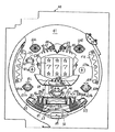
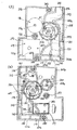
図1は、パチンコ遊技機1の正面図である。図2は、パチンコ遊技機1に設けられる遊技盤40の拡大正面図である。図3は、パチンコ遊技機1の背面図である。図4は、玉払出装置116における分割可能な各ケースの内部構成を透視して示す側面図である。図5は、玉払出装置116を側面側から見た場合の通路切換ソレノイド(振分ソレノイドとも呼ばれる)の動作状態を示すケースの断面図である。図6は、玉払出装置116(CR機用払出しユニットとも呼ばれる)を後面側から見た場合のケースの断面図である。図7および図8は、パチンコ遊技機1に設けられる制御回路のブロック図である。
【0022】
図1〜図3を参照して、パチンコ遊技機1は、縦長な方形状に枠組形成される外枠2と、該外枠2の内側に開閉自在に軸支されかつ弾球遊技機1の主要構成部のほぼすべてが集約して設けられる前面枠3と、該前面枠3の前面上部に開閉自在に軸支されて設けられる前面開閉枠4とから構成されている。また、前面枠3に設けられる主要構成部としては、上記した前面開閉枠4、遊技盤40、上皿19、下皿27、灰皿29、操作ハンドル30、機構部100、および、打球発射装置87がある。また、図示の実施の形態では、パチンコ遊技機1の側方において、遊技者に対し遊技媒体の一例としての遊技玉(遊技用のパチンコ玉)を貸出すためのカードユニット31(記録媒体用の情報処理装置)が付設されている。
【0023】
前面枠3および前面開閉枠4は、パチンコ遊技機1の正面から見て左側の端部において軸支され、パチンコ遊技機1の正面から見て左側の端部を開放端として開閉される。前面開閉枠4には、遊技盤40の遊技領域41をほぼ透視し得る円形透視窓5が開設され、該円形透視窓5の裏面からガラス板が装着されている。また、前面開閉枠4の上側には、円形透視窓5の外周に沿って、複数の飾りランプ6〜8および複数の飾りLED13,14が設けられている。これら飾りランプ6〜8および飾りLED13,14は、遊技状態に応じて点灯または点滅されるものであり、特別の遊技状態の発生時や継続時を遊技者に報知するとともに、遊技の雰囲気を盛り上げるものである。また、円形透視窓5の外周には、払出すべき賞球(景品玉)が不足したこと(後述する球切れスイッチ115が作動したとき)を報知する球切れランプ9や、入賞玉の発生に基づく所定個数の賞球が行なわれる場合に、その旨を点灯により報知する賞球ランプ10が設けられている。この賞球ランプ10は、賞球の未払出個数がある場合に、点灯することにより、賞球が行なわれる旨を報知する。なお、ここでは、賞球の未払出し個数がある場合に賞球ランプ10を点灯させる例を示したが、これに代わり、賞球の未払出し個数がある場合に賞球ランプ10を点滅させることにより、賞球が行なわれた旨を報知するようにしてよい。
【0024】
さらに、円形透視窓5の外周には、前面開閉枠4の上部左右において、遊技の進行に応じて効果音等の音声を発生するスピーカ12a,12bが設けられている。なお、スピーカ12a,12bの前面には、網目状ネット(図示省略)が取付られ、スピーカ12a,12bから発生される音声を通すようになっている。また、円形透視窓5の外周には、遊技盤40に貼付けられる証紙を視認するための透視レンズ39が設けられている。
【0025】
上記した飾りランプ6〜8,9L,10L、球切れランプ9、賞球ランプ10、飾りLED13,14は、図8に示すように、それぞれプリント配線基板で構成される遊技効果ランプ基板6a,7a,8a,9a,10aや遊技効果LED基板13a〜13dに実装されて、図1に示す前面枠3の前面側や前面開閉枠4の裏面側に取付けられている。そして、各遊技効果ランプ基板6a,7a,8a,9a,10aが枠用ランプ中継B基板15に接続され、各LED基板13a〜13dが枠用ランプ中継C基板16に接続されている。枠用ランプ中継B基板15,枠用ランプ中継C基板16は、前面枠3の裏面下部に取付けられる中継基板端子台95に止着される枠用ランプ中継A基板96に接続された後、後述するランプ制御基板80に接続されている。
【0026】
主基板151は、遊技制御用のマイクロコンピュータ151Mを含む。この遊技制御用のマイクロコンピュータは、ワンチップマイクロコンピュータであり、遊技制御用のプログラム等を記憶するROM、ワークメモリとして使用されるRAM、遊技制御用のプログラムに従って制御動作を行なうCPU151a、および、データの入出力用のI/Oポートを含む。このような遊技制御用のマイクロコンピュータ151Mは、定期的(たとえば2msec毎)にリセットされてROMに記憶されている遊技制御プログラムを先頭から繰返し実行し、各種の遊技制御を行なう。
【0027】
なお、枠用ランプ中継A基板15は、前面枠3の前面側に取付けられ(これに対応して遊技効果ランプ基板も前面枠3の前面側に取付けられている)、枠用ランプ中継B基板16は、前面開閉枠4の裏面側に取付けられている(これに対して遊技効果LED基板も前面開閉枠4の裏面側に取付けられている)。なお、図示しないが、前面開閉枠4を開放したことを検出するためにドアスイッチが設けられることがある。この場合には、ドアスイッチの配線は後述する枠用スイッチ中継基板に一旦接続された後、主基板151に入力され、主基板151からの情報信号に基づいてランプ制御基板80によってランプ6〜8、9、10の一部または全部が点灯制御されることにより、前面開閉枠4が開放されたことを報知するようになっている。
【0028】
また、スピーカ12a,12bから延びる配線は、前面開閉枠4の上方における左右裏面に取付けられる音声中継基板17a,17b(図8において、音声中継B基板,音声中継C基板と表示)に一旦接続され、その後、前面枠3の裏面下部に取付けられる中継基板端子台95に止着される音声中継基板97(図8において、音声中継A基板と表示)に接続された後、後述する音声制御基板82に接続されている。音声制御基板82は、主基板151から与えられる音声制御を指令する音声制御信号に応じて、スピーカ12a,12bを駆動制御するものである。音声制御基板82にも、主基板151と同様に、制御用のCPU(後述するCPU82a)、ROM、RAM等を含み、効果音等の音声の制御を行なう音声制御用のマイクロコンピュータ82Mが設けられている。
【0029】
次に、前面開閉枠4の下側に取付けられる上皿19の構成について説明する。上皿19は、複数の合成樹脂製部材を組合せた皿部材を固着することにより構成されている。上皿19の開放側の上方には、玉抜き操作レバー21が設けられている。この玉抜き操作レバー21は、左右方向に移動可能に設けられ、図示しないスプリングの付勢力に抗して一方向に移動させることにより、上皿19に貯留されていた玉を裏面側に形成される玉抜き路(図示しない)を流下させて下皿27に誘導するものである。なお、上皿19には、その内部に圧電ブザーを設けてもよい。この圧電ブザーは、遊技玉の貸出異常が生じたとき(たとえばピッ、ピッ、ピッという連続音)、あるいは遊技玉の貸出時(たとえば、100円相当の遊技玉が払出されるごとにピーという音)に、その旨を報知する報知音が発生されるものである。
【0030】
上記した上皿19について、さらに詳細に説明すると、上皿19は、その上流側に形成される賞球払出口20から払出された賞球を一旦貯留した後、図示しない発射位置に玉を供給するものである。また、上皿19は、パチンコ遊技機1に隣接して設けられるカードユニット31を介して遊技玉の貸出しを受ける際に操作する操作部232とともに、これらを設置する中空の部材である上皿化粧部190の上面側に設けられている。上皿化粧部190に設けられた操作部232は、球貸しスイッチ24、返却スイッチ25(ともに図8参照)、球貸可表示LED(図示省略)、および、残高表示器としての度数表示LED(図示省略)等が実装される残高表示基板23上に設けられており、遊技者により操作可能および視認できるようにスイッチおよび表示器を配して構成されている。この残高表示基板23は、上皿化粧部190の上面側に設けられている。
【0031】
球貸しスイッチ24は、カードユニット31によって遊技玉の貸出し(球貸しおよび貸玉の払出しともいう)を受ける際に操作されるスイッチである。返却スイッチ25は、遊技終了の際にカードユニット31の挿入口34に差込まれたカード(遊技に使用可能なカード)の返却を受ける際に操作されるスイッチである。ここで、遊技に使用可能なカードは、磁気記録式のカードであり、遊技のために使用可能(たとえば球貸しに使用できる)遊技者所有の有価価値(カード残高)が記録可能な記録媒体である。ここで、有価価値は、遊技者に所有され、遊技に使用されるカード残高等のデータをいう。
【0032】
また、度数表示LEDは、カードユニット31のカード挿入口34に差込まれたカードに記録されたカード残高(カード残額)としての度数が表示されるものである。なお、上皿19に設けられる上記した球貸しスイッチ24および返却スイッチ25等が実装される残高表示基板23から延びる上皿配線は、前面枠3の軸支側の下部に形成される配線透視開口(図示しない)から前面枠3の裏側に引出されて後述する払出制御基板144に接続されている。
【0033】
さらに、上皿19の開放側末端には、前面開閉枠4を前面枠3に対して施錠しかつ前面枠3を外枠2に対して施錠する施錠装置84(図3参照)を操作するためのシリンダ錠26が臨んでいる。また、前面開閉枠4の軸支側上部には、玉抜きピン挿入口(図示省略)が形成されている。そして、この玉抜きピン挿入口から図示しない玉抜きピンを差込む操作により、これに連結される玉抜き操作管(図示しない)を上下方向に揺動させて玉抜き口を閉塞したり開放したりするようになっている。
【0034】
なお、前面開閉枠4の軸支側下部には、起伏部が形成され該起伏部に、イヤホーンジャックと、イヤホーンジャックから聞こえる音楽を選択するための選択スイッチとが設けられてもよい。
【0035】
また前面枠3の下部に設けられる下皿27は、上皿19から溢れた賞球であって、余剰球通路(図示省略)を介して接続樋93(図3参照)から排出される余剰の賞球を貯留するものである。下皿27の前面壁には、玉抜き操作レバー28がスライド可能に取付けられるようになっている。この玉抜き操作レバー28を操作することにより、下皿27に貯留されていた賞球を下方に玉抜きして持ち運び可能な玉箱に移替えることができる。また、下皿27の左側には、灰皿29が設けられ、右側には操作ハンドル30が設けられている。操作ハンドル30は、図3に示す打球発射装置87の発射モータ88の駆動を開始させる単発発射スイッチ91およびタッチセンサ92(ともに図9に符号だけ表示)を内蔵しているとともに、弾発力を調節するものである。
【0036】
パチンコ遊技機1の正面構造は、概ね上記したとおりであるが、図示の実施の形態では、パチンコ遊技機1にカードユニット31が隣接配置されている。このカードユニット31は、上皿19の上面に設けられる前述した球貸しスイッチ24や返却スイッチ25等の操作部を操作することにより作動されるものであり、カードの情報処理等の所定の処理を行なうマイクロコンピュータおよびカードリーダライタ等の各種機器が設けられている。カードユニット31は、マイクロコンピュータにより動作が制御される。カードユニット31には、使用可能状態であるか否かを表示する使用可能表示器32と、当該カードユニット31がいずれの側のパチンコ遊技機1に対応しているかを表示する連結台方向表示器33と、記録媒体としての磁気カードを挿入するカード挿入口34とが設けられている。
【0037】
このように構成されるカードユニット31は、独自の制御回路によって制御されるものであり、図3に示されるように、カードユニット配線35を介し、パチンコ遊技機1と接続されている。パチンコ遊技機1においては、カードユニット配線35が払出制御基板144に接続されており、払出制御基板144を介してカードユニット31と信号の送受信を行なう。また、カードユニット31には、パチンコ遊技機1の電源コード135とは別の独立した電源コード311から電源電力が供給されている。この電源コード311は、接地極を有するコードである。このため、カードユニット31は、電源コード311を介して電気的に接地している。
【0038】
一方、パチンコ遊技機1の背面には、図3に示すように、入賞玉の発生に基づいて所定個数の賞球を払出すための各種の機構を装備した機構部100が設けられている。操作ハンドル30に対応する裏面には、発射モータ88および打球樋(図示しない)を有する打球発射装置87が固着されている。その打球発射装置87の側方には、機構部100に設けられた前述の余剰球通路を流下する賞球を下皿27に誘導する接続樋93が固着されている。さらに接続樋の側方に中継基板取付台95が取付けられている。外枠2に対する前面枠3の開放側裏面には、外枠2の掛止片85に対する前面枠3の施錠および前面枠3に対する前面開閉枠4の施錠を行なう施錠装置84が設けられている。
【0039】
上記した構成のうち、打球発射装置87には、発射制御基板90が付設されており、この発射制御基板90によって、打球発射装置87が駆動制御されるようになっている。なお、発射制御基板90は、図3に示すように、発射制御基板カバー89によって被覆され、この発射制御基板カバー89から外部に露出している位置に設けられるコネクタを介して払出制御基板144と接続されており、所定の状態となったときに払出制御基板144から停止信号を受けて打玉の発射を行なえないようになっている。また、中継基板取付台95には、枠用ランプ中継A基板96、音声中継A基板97、発射中継B基板98、および、発射中継A基板99が所定の位置に取付けられている。
【0040】
以上で、パチンコ遊技機1の全体の概略構成を説明したが、以下、パチンコ遊技機1を構成する要素のうち、遊技盤40と、機構部100とのそれぞれの詳細な構成について順次説明する。
【0041】
まず、図2および図3を参照して、遊技盤40について説明する。遊技盤40の正面構造について図2を参照して説明する。遊技盤40は、前面枠3の裏面側に一体的に形成される遊技盤収納枠36に収納固定されるべく、ほぼ正方形状の合板により形成されている。遊技盤40の表面には、円形渦巻状に誘導レール42が取付けられている。該誘導レール42の内側は、遊技領域41とされて発射された打玉が落下するものである。遊技領域41には、図示の場合、特別可変表示装置44、特別可変入賞球装置48、普通可変入賞球装置58、普通図柄表示器63等が設けられるとともに、打玉を入賞とする入賞口、打玉を通過させる通過口、打玉の流下方向、速度を変化せしめる風車または多数の障害釘が設けられている。また、遊技領域41の最下方には、いずれの入賞領域にも入賞しなかった打玉が取込まれるアウト口69が設けられている。
【0042】
遊技領域41の構成をその遊技動作に従って詳細に説明する。遊技領域41の中央よりもやや下方の左側には、遊技領域41を落下する打玉が通過可能に設けられた通過口(ゲート)620と、その通過口620を通過した打玉(通過玉)を検出するゲートスイッチ(通過検出器)62とが設けられている。
【0043】
遊技領域41のほぼ中央に配置される特別可変表示装置44の上方には、普通図柄可変表示装置としての普通図柄表示器63が設けられている。なお、本実施形態においては、当りLEDとはずれLEDとの2つのLEDを普通図柄表示器63としているが、一般的には7セグメントLEDなど、数字を表示可能なものを使用する。普通図柄表示器63は、ゲートスイッチ62の検出信号に基づいて所定期間可変表示した(交互点滅させる)後、表示結果を導出表示する(どちらか一方を点灯させる)。普通図柄表示器63の両側方には、普通図柄表示器63の可変表示中にゲートスイッチ62を通過した打玉数を記憶表示する普通図柄記憶LED64(最高4個まで記憶表示する)等が設けられている。普通図柄表示器63の表示結果が予め定められた当り図柄(当りLED点灯、また7セグメント表示器を使えば0〜9までの数字の可変表示において、7が停止表示された場合など)である場合には、普通可変入賞球装置58が所定時間開放される。なお、普通図柄表示器63の可変表示時間は、通常確率モードのときに相対的に長く(たとえば、30秒)、確率変動モードのときに相対的に短く(たとえば、3〜5秒)設定されている。
【0044】
普通可変入賞球装置58は、遊技領域41のほぼ中央に配置される特別可変表示装置44と遊技領域41のアウト口69の上部に配置される特別可変入賞球装置48との間に配置され、ソレノイド59によって開閉駆動される電動チューリップタイプの可変入賞球装置である。そして、普通可変入賞球装置58には、始動入賞検出器としての第1種始動口スイッチ60が内蔵され、開放中または閉成中に受入れた入賞玉を検出するようになっている。打玉が第1種始動口スイッチ60によって検出されると、特別可変表示装置44が特別図柄と呼ばれる複数種類の識別情報の可変表示を開始する。普通可変入賞球装置58の開放時間は、通常確率モードのときに相対的に短く(たとえば0.5秒)、確率変動モードのときに相対的に長く(たとえば2秒)設定されている。また、普通可変入賞球装置58が開放していない場合でも打玉を受入れるようになっている。
【0045】
特別可変表示装置44は、複数の図柄を可変表示する液晶タイプの可変表示器からなり、遊技領域41のほぼ中央に配置される。そして、特別可変表示装置44での可変表示の停止時における図柄の組合せが予め定められた大当り図柄の組合せ(たとえば同一の図柄が当りラインのいずれかに揃った場合)である場合には、大当り遊技状態となって特別可変入賞球装置48が次に説明するような所定の態様で開閉駆動される。大当り図柄の組合せの一部は確率変動図柄として設定されている。この確率変動図柄で大当り遊技状態となったときには、その大当り遊技状態終了後における普通図柄表示器63における当り図柄の出現確率や特別可変表示装置44における大当り図柄の出現確率が高くなる確率変動モードとなるように制御される。特別可変表示装置44は、遊技盤40の表面側に取付けられる飾り基板(符号なし)を備えている。
【0046】
また、特別可変表示装置44の上部には飾りLED45が設けられ、下部には飾りLED45aが設けられている。さらに、特別可変表示装置44の下部中央には、特別可変表示装置44の可変動作中に第1種始動口スイッチ60によって検出された玉数を記憶表示する特別図柄始動記憶LED46(最高4個まで記憶表示する)が取付けられている。
【0047】
大当り遊技状態となったときに駆動制御される特別可変入賞球装置48は、開放された場合に打玉の入賞が可能になる大入賞口が設けられており、大入賞口扉用のソレノイド50によって開閉駆動される開閉板としての大入賞口扉49が大入賞口を開閉可能な態様で設けられている。
【0048】
特別可変入賞球装置48の内部には、大入賞口扉49に受入れられた打玉を検出するために、特定玉検出器としての特定領域スイッチ51および入賞個数検出器としてのカウントスイッチ52が設けられている。
【0049】
大入賞口扉49の開放時に大入賞口から特別可変入賞球装置48内に入った玉は、最終的にすべてカウントスイッチ52に向けて誘導され、カウントスイッチ52により検出される。また、特別可変入賞球装置48内に入った玉のうち、特定領域スイッチ51により検出された玉は、その後、カウントスイッチ52に向けて誘導され、カウントスイッチ52により検出される。したがって、特別可変入賞球装置48内に入った玉は、結果的にすべてカウントスイッチ52により検出される。
【0050】
大当り遊技状態となった場合には、一定時間(たとえば28秒)が経過するまで、または、その一定時間内に所定個数(たとえば、10個)の入賞玉が入賞するまで大入賞口扉49を開放(以下、この開放を開放サイクルという)し、その開放サイクル中に受入れられた打玉が特定領域スイッチ51によって検出されたときに継続権が成立して、再度上記した開放サイクルが実行され、各開放サイクルにおいて継続権が成立していることを条件に最高16回の開放サイクルを繰返すことができるようになっている。
【0051】
特別可変入賞球装置48の内部においては、シーソー式の玉振分部材としての大入賞口内誘導板が設けられている(図示省略)。この大入賞口内誘導板は、特定領域スイッチ51の方向へ向けて傾斜した状態と、特定領域スイッチ51とは逆の方向へ向けて傾斜した状態とのいずれかの状態に切換え可能となるようにソレノイド(後述する大入賞口内誘導板用のソレノイド53)により駆動制御される。その場合、大入賞口扉49が1回開放されたとき(1サイクル中)には、特定領域スイッチ51が玉を1個検出するまでは、振分部材が特定領域スイッチ51の方向へ向けて傾斜した状態にされることにより、玉が特定領域スイッチ51により検出されやすい状態にされ、特定領域スイッチ51が玉を1個検出した後は、振分部材が特定領域スイッチ51とは逆方向へ向けて傾斜した状態にされることにより、玉が特定領域スイッチ51により検出がされにくい状態にされる。
【0052】
なお、この実施の形態では、特定領域スイッチ51への入口に大入賞口内誘導板を設けた例を示したが、これに限らず、大入賞口内誘導板の代わりに、次のようなシャッタを設けてもよい。このシャッタは、ソレノイドにより駆動され、開放サイクルの1サイクル毎に、特定領域スイッチ51が玉を1個検出するまでは開放状態にされている。そして、特定領域スイッチ51が玉を1個検出すると閉塞状態に制御される。このような制御が行なわれることにより、大入賞口扉49が1回開放された場合(1サイクル中)には、特定領域スイッチ51が玉を1個検出するまでは、特定領域スイッチ51による玉の検出が可能な状態にされ、特定領域スイッチ51が玉を1個検出した後は、特定領域スイッチ51による玉の検出が不可能な状態にされる。
【0053】
さらに、特別可変入賞球装置48には、入賞玉検出器としての右落とし入賞口スイッチ55a,左落とし入賞口スイッチ55bを内蔵する通常入賞口54a,54b、大入賞口扉49が開放していることを表示する飾りLED56C、継続権が成立していることを報知する飾りLED56R、および、大当り遊技状態で継続権が未成立である旨を報知する飾りLED56L、および、大当り遊技状態中などに点灯する飾りLED57が設けられている。
【0054】
また、遊技領域41には、上記した構成以外に、袖飾りランプ65Lb,65Rb、入賞玉検出器としての左袖入賞口スイッチ65Laを内蔵する入賞口65L、入賞玉検出器としての右袖入賞口スイッチ65Raを内蔵する入賞口65R、風車66、サイド飾りランプ67Laを内蔵するサイド飾り67L、サイド飾りランプ67Raを内蔵するサイド飾り67R等が設けられている。
【0055】
以上に示した各種ランプおよび各種LEDは、すべてランプ制御基板80により表示制御(駆動制御)される。ランプ制御基板80は、ランプ制御用のCPU(後述するCPU80a)、ROM、RAM等を含み、ランプ制御を行なうランプ制御用のマイクロコンピュータ80Mが設けられており、主基板151から与えられるランプ制御を指令するランプ制御信号に応じて、上記した各種ランプおよび各種LEDを制御する。
【0056】
以上に説明した実施の形態において、打球が入賞する入賞口および入賞装置には、入賞玉を検出するための検出用のスイッチ51,52,55a,55b,60,65La,65Raがすべて設けられている。これら検出用のスイッチのうち、スイッチ52,55a,55b,60,65La,65Raは、検出信号に基づいて所定個数の賞球を払出すために使用されるものである。また、特定領域スイッチ51は継続権の成立を検出するために使用され、カウントスイッチ52は大入賞口扉49の開放を規制するための玉計数機能を兼用している。
【0057】
スイッチ51,52,55a,55b,65La,65Raは、図8に示すように、次に説明するスイッチ中継基板77を介して主基板151に接続される。主基板151では、これらのスイッチからの検出信号を記憶するとともに順次払出制御基板144に払出す賞球個数等を指令する賞球制御信号を導出して入賞に対応する賞球を払出するように、後述する球払出装置116を駆動制御するようになっている。入賞玉をスイッチが検出した場合に払出される賞球の個数は、入賞の種別に応じて複数種類定められており、第1種始動口スイッチ60により検出された始動入賞玉については、1個の検出につき5個の賞球の払出しが行なわれ、それ以外の検出スイッチにより検出された入賞玉については、13個の賞球の払出しが行なわれるように決定され、賞球制御信号により賞球個数が指令される。また、カウントスイッチ52で検出された場合は、15個の賞球払出しをし、それ以外は5個の賞球払出しをしてもよいし、始動入賞(第1種始動口スイッチ60の検出)で5個の賞球払出し、大入賞口入賞(カウントスイッチ52の検出)で15個の賞球払出し、それ以外を10個の賞球払出しとしてもよいのである。
【0058】
払出制御基板144には、払出制御用のプログラム等を記憶するROM、ワークメモリとして使用されるRAM、払出制御用のプログラムに従って制御動作を行なうCPU144j、および、データの入出力用のI/Oポートを含み、賞球および貸玉の払出制御を行なう払出制御用のマイクロコンピュータ144M(ワンチップマイクロコンピュータ)が設けられている。
【0059】
賞球制御信号は、指令内容を示すコマンド(賞球制御信号CD0〜CD7ともいう)と、コマンドの取込みタイミングを示すINT信号(賞球制御信号INTともいう)とを含む。ここで、賞球制御信号のコマンドは、1コマンドが2バイトのデータで構成されており、賞球払出モードと払出停止モードとの2種類のモードのいずれかを指定(指令)する1バイトのMODEと呼ばれるコマンドデータと、払出個数、払出動作停止、払出動作再開のいずれかを指定(指令)する1バイトのEXTDATAと呼ばれるコマンドデータとにより構成される。遊技制御用のマイクロコンピュータ151Mは、このような2バイトのデータを順次送信することにより、払出制御内容を指令する。このような賞球制御信号の指令に応じて、払出制御用のマイクロコンピュータ144Mが賞球の払出制御を行なう。
【0060】
また、始動玉検出器としての第1種始動口スイッチ60は、図8に示すように、中継基板77を介することなく直接的に主基板151と接続されて始動信号と入賞信号(ただし他の検出用スイッチ52,55a,55b,65La,65Raでの入賞玉の検出に基づいて払出される賞球個数は、相対的に多い個数、たとえば13個であるのに対し、第1種始動口スイッチ60での入賞玉の検出に基づいて払出される賞球個数は、相対的に少ない個数、たとえば5個である)とを入力している。これは、第1種始動口スイッチ60からの配線を直接主基板151に接続することにより、その途中に不正な回路基板を組込んだ配線(ぶら下がり基板等と称されている)が接続されているか否かの発見を容易にするためである。また、第1種始動口スイッチ60と主基板151とを直接接続する配線は、他の配線の色と明らかに異なる色(本実施の形態の場合には、ピンクと黄の蛍光色)としたので、この点からも第1種始動口スイッチ60からの配線に不正が行なわれているか否かを見分けやすい。
【0061】
遊技盤40の遊技領域41には、前述したようにスイッチやソレノイド、あるいは飾りランプや飾りLED等の電気的部品が多数設けられるが、これらは、次に説明する第1入賞玉誘導カバー体70の裏面に取付けられるランプ中継基板76,スイッチ中継基板77を介して主基板151やランプ制御基板80に接続されるようになっている。
【0062】
図8に示すように、遊技盤面に設けられる各スイッチ51,52,55a,55b,62,65La,65Ra、および、各ソレノイド50,53,59は、スイッチ中継基板77を介して主基板151に接続されている。
【0063】
また、遊技盤面に設けられる飾りランプを実装している飾りランプ基板56,66a,67a、遊技盤面に設けられる飾りLEDを実装している飾りLED基板45,57、および、記憶表示LED46,64は、それぞれがランプ中継基板76を介してランプ制御基板80に接続されている。
【0064】
一方、遊技盤40の裏面には、図3に示すように、特別可変表示装置44の裏面が突出して設けられている。この特別可変表示装置44の裏面部分には、表示制御基板としての図柄制御基板75が図柄制御基板カバー74に被覆されて取付けられている。図柄制御基板75は、特別可変表示装置44および普通図柄表示器63のそれぞれでの図柄の可変表示制御である図柄制御を行なうマイクロコンピュータ75Mを含む。マイクロコンピュータ75Mは、図柄制御用のCPU(後述するCPU75a)、ROM、RAM等を含み、特別可変表示装置44および普通図柄表示器63のそれぞれの図柄制御(可変表示制御)を行なう。マイクロコンピュータ75Mは、主基板151から図柄制御を指令する図柄制御信号を主基板151から受け、その指令にしたがって、特別可変表示装置44の可変表示器の可変表示動作を制御するとともに、普通図柄表示器63の可変表示動作も制御する。
【0065】
また、上記した特別可変表示装置44の裏面の周囲には、特別可変表示装置44の上方に位置する入賞口(本実施の形態では、入賞口47)に入賞した入賞玉を誘導する入賞玉誘導路がその前面に形成されるカバー体である第1入賞玉誘導カバー体70が取付けられ、この第1入賞玉誘導カバー体70に連通するように、その下部に第2入賞玉誘導カバー体71が取付けられている。
【0066】
第1入賞玉誘導カバー体70には、その中央に特別可変表示装置44の裏面が貫通する窓孔72が形成されるとともに、一側後面にランプ中継基板76および盤用外部端子基板78が取付けられている。また、図柄制御基板カバー74よりも下方には、スイッチ中継基板77が設けられている。ランプ中継基板76,スイッチ中継基板77は、前述したように、遊技盤40の遊技領域41に設けられるスイッチ、ランプ、ソレノイド、LED等の電気部品と主基板151またはランプ制御基板80との接続を中継するものである。
【0067】
盤用外部端子基板78は、図8に示すように、パチンコ遊技機1の営業管理上必要な遊技情報(たとえば大当り遊技状態中である旨を報知する大当り1情報、確率変動図柄で大当り遊技状態となり、その大当り状態中およびその大当りによる確率変動中である旨を報知する大当り2情報(大当り中と確率変動中に出力され続ける信号)、確率変動図柄による大当り状態終了後の確率変動中である旨を報知する確率変動情報、第1種始動口スイッチをONした打玉の数を報知する始動口情報、特別可変表示装置の可変表示動作回数を報知する図柄確定回数1情報、普通可変表示装置の可変表示動作回数を報知する図柄確定回数2情報、および、普通可変入賞球装置の開閉回数を報知する役物回数情報等)を遊技場に設置される管理コンピュータに出力するための外部接続端子78bを有し、遊技情報が主基板151から与えられるようになっている。さらに、どの図柄で大当りしたか、どの図柄で停止したか等の情報を出力するようにしてもよい。
【0068】
また、第2入賞玉誘導カバー体71の後面側には、その内部にランプ制御基板80および音声制御基板82を収納する制御基板ボックス161が取付けられている。
【0069】
以上、遊技盤40の構成について詳細に説明してきたが、上記のように構成される遊技盤40は、前面枠3の裏面側に形成される遊技盤収納枠36に収納固定されるようになっている。遊技盤収納枠36は、周知のように、ほぼ正方形状に構成される遊技盤40を収納するように前面枠3の裏面に段差状に形成されている。収納した遊技盤40の裏面を押圧固定するための遊技盤係止レバー86が、遊技盤収納枠36の適宜箇所に取付けられている。また遊技盤収納枠36の下方部は、平板状の支持板となって遊技盤40の下辺を載置するようになっており、その支持板のほぼ中央にアウト玉を誘導するアウト玉誘導通路が形成されている。また、遊技盤40を遊技盤係止レバー86によって収納固定した状態においては、その裏面から機構部100が被覆されることとなる。機構部100は、遊技板収納枠36の内側側面において上部および下部に分かれて固定される導電性の2つの軸受金具37,37のそれぞれにおいて上方向に向けて突設される導電性(金属製)の軸ピン38に、機構部100において上下方向に延在された態様で固定された金属製の取付部材148の上部および下部のそれぞれに形成された軸支部の掛止め孔をそれぞれ係止することにより、開閉自在に軸支される。また、機構部100は、遊技盤収納枠36の適宜位置に植立される係止ピン(図示しない)と機構部100に設けられる機構部係止レバー149とを係合させることにより、機構部100を閉じた状態で保持することができるようになっている。ここでは、機構部100が前面枠3に対して開閉自在である場合を例として示したが、これに限らず、機構部は前面枠3に対して固定されて開閉できないものであってもよい。
【0070】
次に、パチンコ遊技機1の背面に設けられる機構部100の構成について図3を参照して説明する。図3において、機構部100は、貯留タンク105と、上部構成部と、中間構成部と、下部構成部とが背面から見て開口窓102を構成するように機構部主体101上に一体的に形成されている。
【0071】
貯留タンク105は、主として賞球を貯留する玉供給部としてのものである。上部構成部は、貯留タンク105に貯留された賞球を下流側に整列しながら誘導する玉整列レール部材108およびカーブレール部材111が設けられるものである。中間構成部は、カーブレール部材111からの玉を誘導する玉通路114と入賞玉に基づく賞球を払出す球払出装置116とが設けられるものである。下部構成部は、主として遊技盤に打込まれた入賞玉を含む打玉を処理する処理機構が設けられるものである。
【0072】
機構部100を閉じた状態において遊技盤40の裏面収容部が開口窓102から外部に臨むようになっている。このため、遊技盤40の裏面構造が前述したように特別可変表示装置44の裏面および制御基板ボックス161を有する複雑なものであっても、機構部100の開閉動作をスムーズに行なうことができる。なお、開口窓102の中央よりやや下方には、その開口窓102の両側端から掛け渡した状態で後方に突出形成された横架突出板103が設けられ、その横架突出板103に、後述する主基板ボックス150の上部が取付けられるようになっている。ただし、ランプ制御基板80に実装されるコネクタ80a〜80cおよび音声制御基板82に実装されるコネクタ82a〜82cは、横架突出板103の上方に位置して開口窓102から外部に臨むようになっている。
【0073】
そこで、以下、機構部100の構成について説明する。まず、機構部100の上部構成部には、多量の賞球を貯留する貯留タンク105と、該貯留タンク105から供給される賞球を仕切り壁によって2列に整列して流下させる玉整列レール部材108と、その玉整列レール部材108によって誘導された賞球を後述する球払出装置116に向けて方向転換するカーブレール部材111と、そのカーブレール部材111の上方に設けられた枠用外部端子基板132とがそれぞれ所定の位置に設けられている。
【0074】
貯留タンク105は、その底面に揺動自在に軸支されて図示しないばねにより上方向に付勢される球切れ情報検知レバー106が設けられ、その球切れ情報検知レバー106の下方に、球切れ情報検出スイッチ107が固定されている。この球切れ情報検出スイッチ107は、図9に示すように、枠用外部端子基板132に接続されて貯留タンク105内に賞球が不足したときに図示しない管理コンピュータに球切れ信号を出力するようになっている。上記した貯留タンク105の下流側に配置される玉整列レール部材108は、上部構成部の一端から他端に向けて傾斜状に取付けられ、その内部中央に仕切り壁(図示しない)が立設されて貯留タンク105から流出した賞球を下流に向かって3列に整列させるようになっている。
【0075】
また、玉整列レール部材108の下流側上部には、玉ならし部材109が支軸を支点として揺動自在に垂下され、玉整列レール部材108上を上下2段となって流下する賞球を玉ならし部材109に埋設される重錘の作用によって1段とするようになっている。
【0076】
前述した玉整列レール部材108の下流側上部には、外部との信号線が接続される外部接続端子133を有する枠用外部端子基板132が設けられる。枠用外部端子基板132に設けられる外部接続端子133は、外部(たとえば、管理コンピュータ)と弾球遊技機との間の信号線を接続する球切れ情報出力端子、玉貸情報出力端子、賞球情報出力端子等を有し、さらに、球切れ情報検出スイッチ107が接続されるコネクタ132a、および、払出制御基板144が接続されるコネクタ132b等を有して構成されている。また、情報端子基板132の近傍となる機構部100の裏面には、パチンコ遊技機1の運搬時に電源線135を束ねておくためのフック(図示省略)が形成されている。これにより、運搬時における電源線135および差込みプラグ135aの破損を防止することができる。なお、電源線135には、ヒューズケースが一体的に設けられている。
【0077】
上部構成部には、上記した構成以外に、その開放端部および枠用外部端子基板132の上部に対応する位置に機構部係止レバー149が一端を支持されて回動自在に設けられている。機構部係止レバー149には、遊技盤収納枠36の所定の位置に植立固定される係止ピン(図示しない)の先端部と係合する溝が形成されている。この機構部係止レバー149の溝と係止ピンとの係合を解除するように回動させることにより、機構部100の遊技盤収納枠36への固定状態を解除することができる。なお、機構部係止レバー149は、上部構成部の開放端部および下部構成部の開放端部に設けられているため、機構部100の遊技盤収納枠36への固定状態を堅固に安定化させることができるようになっている。
【0078】
次に、機構部100の中間構成部の上部には、玉整列レール部材108の下流端に連通して賞球の向きを180度変換して導くカーブレール部材111が設けられている。このカーブレール部材111も賞球を3列に整列して下流側に導くように区画形成されている。また、カーブレール部材111のヘアピン状の屈曲部には、図示しない玉抜き弁が揺動自在に設けられ、その玉抜き弁の側方から下流側に向けて玉抜き通路112が形成されている。玉抜き通路112は、玉抜き弁が操作されたとき(たとえば、営業が終了して貯留タンク105に貯留される賞球を外部に抜く必要が生じたとき)、貯留タンク105および玉整列レール部材108に貯留されていた賞球を弾球遊技機1の外部に誘導するものである。
【0079】
また、カーブレール部材111の下流側には、垂直状に玉通路部材が設けられる。具体的には、左右2列の玉通路114から玉通路部材が構成され、この2列の玉通路114には、それぞれ球切れスイッチ115が通路に臨むように設けられている。この球切れスイッチ115は、図7に示すように、枠用スイッチ中継基板142を介して主基板151に接続され、球切れスイッチ115が玉を検出しなくなったときには、次に説明する球払出装置116に設けられた払出モータ118(図8参照)の作動を停止して玉の払出しを不能動化させるようになっている。ここで、払出モータ118は、ステッピングモータにより構成されており、1回の払出し動作により払出される最大払出個数(連続払出数ともいう)が25個に設定されている。
【0080】
球切れスイッチ115は、払出す玉の1回の最大払出個数(たとえば25個)分以上の玉が玉払出装置116内および玉通路114内に入っている場合に、それらの玉のうちの最上端に位置する玉を検出できるように検出位置が設定されている。したがって、球切れスイッチ115が玉を検出しなくなったときには、払出す玉数が1回の最大払出個数(25個数)に満たない状態(球切れ状態)であることが検出されるのである。
【0081】
上記した玉通路114の下方には、球払出装置116が取着される。球払出装置116は、ほぼ直方体形状をなすケース(図7等参照)の内部に収納されて機構部主体101の裏面側に着脱自在に取付けられるようになっている。球払出装置116には玉の払出のために動作する各種部材の他に、玉の払出動作を確実に行なうために払出モータ118の停止位置(正確には、回転部材の停止位置)をフォトセンサを用いて検出するモータ位置センサ122(図8参照)も設けられている。具体的に、このモータ位置センサ122は、後述する図4のギヤ212に設けられた検出突片216を、後述する図8に示される中継基板223に設けられたフォトセンサを用いて検出することにより、払出モータ118の停止位置を検出する。
【0082】
次に、図4〜図6を参照して、球払出装置116の構成を詳細に説明する。玉払出装置116は、図6に示すように、ケース201内に集約して形成されるが、このケース201は、左,中,右に3分割(ケース201a〜201c)されてそれらを組付けることにより完成される。中,左の各ケース201b,201cには、相互に対向する側に、前述した2列の玉通路114と連通する玉通路203(各ケース201b,201cの内部構造は、ほぼ左右対称であるため符号のb,cを省略する)が「く」字状に屈曲形成されており、その玉通路203の上端の玉入口202から入った賞球を玉通路203の途中に設けたスプロケット205で1個づつ区切って玉通路203の下端の排出口204から排出するようになっている。排出口204は、前後方向に並列する2つの排出口204a,204bからなる。前側の排出口204aは、玉払出装置116から排出する玉を貸玉として払出す貸玉排出口204aとして構成される。後側の排出口204bは、玉払出装置116から排出する玉を賞球(景品玉)として払出す賞球排出口204bとして横成されている。また、排出口204aには、排出口204aから排出される玉数(貸玉数)を検出する(具体的には、払出された貸玉を検出したことに応じて検出信号を出力する)ための球貸し個数カウントスイッチ119が設けられている。排出口204bには、排出口204bから排出される玉数(賞球数)を検出する(具体的には、払出された賞球を検出したことに応じて検出信号を出力する)ための賞球個数カウントスイッチ120が設けられている。
【0083】
スプロケット205は、玉通路203の屈曲部の下方に臨むように回転軸206にワッシャ(図示省略)を介して回転自在に軸支されるものである。より詳細に説明すると、スプロケット205は、細長形状の円柱部材208の右端側に鍔状の円盤部(図示省略)が形成されている。この円盤部両側面には、それぞれ玉を受け入れる間隔を保持して突設される複数(3つ)の突出部210が形成されている。これにより、各突出部210の間は、玉を受入れ誘導するための凹部211として形成されている。また、円柱部材208の左端には、ギヤ212の中心部に穿設された嵌合穴213に内嵌する内嵌部214が形成されている。これにより、スプロケット205は、ギヤ212と一体的に回転するようになっている。なお、ギヤ312の一側面には、外周に沿って複数の検出突片216が突設されている(図4参照)。また、スプロケット205の取付けは、円柱部材208の中心に穿設された中心穴(図示省略)を、ケース321cのほぼ中心よりもやや上方に挿入支持される回転軸206に挿入して行なう。これにより、スプロケット205は、回転自在に支持される。回転軸206の他端は、ケース301aを組み付けたときに、ケース201aに形成される支持穴(図示省略)に支持されるようになっている。
【0084】
上記のように回転自在に軸支されるスプロケット205は、玉通路203の前方に形成されるモータ収容空間(図示省略)に収容支持される払出モータ118によって回転駆動される。即ち、払出モータ118は、ケース201bの側面に穿設された開口を閉塞するように設けられるモータ固定板(図示省略)に固定される。そのモータ固定板の前方に突出された出力軸218a(図5参照)には、前述した開口を挿通してギヤ320が固着される。このギヤ220は、前記ギヤ212と噛金するようになっている。なお、各ギヤ212,220は、各ケース201a,201bの問に形成される収容空間内に配置される。また、払出モータ118は、前述したように、各種電子部品が実装される払出ユニット中継基板124に接続される。払出ユニット中継基板124のコネクタ221aには、払出制御基板144からの配線(払出制御基板144との信号線)が接続される一方、コネクタ221bには、主基板151からの配線(枠用スイッチ中継基板142により中継された主基板151からの信号線)が接続される。なお、払出制御基板144および主基板151からの配線は、別の中継基板をさらに介して中継されるものであってもよい。
【0085】
また、払出ユニット中継基板124には、前述した払出モータ位置センサ122(フォトセンサ)が設けられる払出モータ位置センサ基板223、球貸し個数カウントスイッチ119、賞球個数カウントスイッチ120、および、通路切換ソレノイド117が接続される。具体的には、主基板151に賞球個数カウントスイッチ120の検出信号が入力されるように接続され、払出制御基板144には、払出モータ位置センサ122、賞球個数カウントスイッチ120および球貸し個数カウントスイッチ119の検出信号が入力され、払出制御基板144から払出モータ118に駆動信号(発射制御信号)が出力されるように接続されるとともに、払出制御基板144から通路切換ソレノイド117へ駆動信号(ソレノイド制御信号)が出力されるように接続される。
【0086】
払出ユニット中継基板124は、該基板に穿設される位置決め穴(図示省略)に対してケース201bに突設される位置決め突起(図示省略)が嵌入された状態で、払出ユニット中継基板124に穿設される取付穴(図示省略)を介してケース201bに形成された取付ボスにビス止めされる。また、センサ基板223は、該基板223に穿設される取付穴227を介してケース201aに形成された取付ボス(図示省略)にビス止めされる。
【0087】
ここで、払出ユニット中継基板124においては、2つのコネクタ221a,221bは、大きさが異なっている。払出ユニット中継基板124により、主基板151へ信号を送る信号線(枠用スイッチ中継基板142を介した信号線)と、払出制御基板144からの信号の送受信を行なう信号線とが中継されるが、コネクタ221a,221bの大きさが異なるので誤配線することがない。また、払出ユニット中継基板124は、ケース201内に収容されるので外部から保護されている。ケース201bとケース201cとのネジ止めは、予め定められたネジ穴にそれぞれネジ242,243を螺着する等の固定方法を用いて行なわれる。
【0088】
また、上記した各ケース201b,201cの組付け状態においては、払出モータ118の出力軸218aに固定されるギヤ220(以下、小径ギヤという)と、スプロケット205に一体的に取り付けられるギヤ212(以下、大径ギヤという)とが噛合した状態となる(ギヤ比は、1対2)。スプロケット205は、図5に示すように、回転に伴ってその突出部210及び凹部211が玉通路203の内部に侵入するようになっており、玉通路203の屈曲部で突出部210聞く凹部211)に受け入れた玉を収容したまま回転して斜め下方地点でリリースして貸玉排出口204a又は賞球排出口204bから玉を払出すようになっている。なお、スプロケット205の大径ギヤ212の左右に形成される突出部210と凹部211とは、図6に示すように、相互に互い違いに形成されている。このため、一方の玉通路203から払出される玉と他方の玉通路203から払出される玉とは、同時に払出されることはなく、交互に払出されることとなる。また、スプロケット205の回転位置は、前述した払出モータ位置センサ122によって検出される。即ち、払出モータ位置センサ122は、大径のギヤ212の裏面に突出形成される検出突片216がセンサの検出位置を横切ることによる光の非検出状態が生じたことに基づいて、スプロケット205の回転位置を検出するようになっている。
【0089】
また、玉通路203の上流側(スプロケット205の上方側)における各ケース201b,201c間には、前記2列の玉通路と個々に連通する左右の玉通路203を仕切るための仕切板247が設けられる。一方、玉通路203の下流側(スプロケット205の下方側)には、仕切板247は設けられず、左右2列分の幅の玉通路203が中央に傾斜し、1列分の幅(玉1個が流下する幅)となり(図6参照)、その1列となった玉通路203の下方では、玉通路203が前後2列に分れる。そして、その玉通路203の分岐点、言い換えればスプロケット205から送り込まれた玉を貸玉排出口204aに送る球貸し通路203c(図5(B)に示す通路状態)と、賞球排出口204bに送る賞球通路203d(図5(A)に示す通路状態)との間でその玉通路を切換える通路切換弁250が設けられている。通路切換弁250は、下端部に穿設された挿通穴に回転軸252が挿通され、その回転軸252の両端部がケース201b,201cに突設された取付ボスの各嵌入穴に嵌入して取り付けられることで、回転軸252に回転自在に軸支されるものである。また、通路切換弁250の左側端部には、係合突起255が突設されている。該係合突起255の先端部分は、ケース201bに穿設された挿通穴を挿通して各ケース201a,201b間に形成される収容空間に配され、後述する連結部材263に係合して設けられる。また、通路切換弁350は、図5に示すように、横から見て湾曲した形状、言い換えれば図5(B)に示す通路切換状態で、湾曲した玉通路に沿った形状をなしていて、玉受け面が凹状にへこんでいる。このため、通路切換弁250が玉通路の一部分を構成する際でも、滑るように玉を誘導することができる。これにより、スムーズな玉の流下を招来することができると共に、通路切換弁250の耐久性の向上が図れる。
【0090】
また、通路切換弁250の先端部と当接する玉通路203内には、切換弁350の先端部が玉通路203内で突出しないように凹部257が形成されている。このため、通路切換弁250によって切換えられたいずれの通路形状(図5(A)及び図5(B)に示す各通路状態)においても、玉の流下を妨げないようになっているので、スムーズな玉の流下を招来し、通路切換弁250の先端を保譲できる。
【0091】
上記のように回転自在に軸支される通路切換弁250は、各ケース201a,201b間に形成される収容空間に収容支持される通路切換ソレノイド117によって回転駆動される。即ち、通路切換ソレノイド117は、前述したモータ収容空間の下側となるケース201bの側面にビス止め固定され、そのプランジャーの先端には、連結部材263がネジ止めによって固着される。この連結部材263には、通路切換ソレノイド117のプランジャーの先端を挿入する挿入穴(図示省略)と、前述した係合突起255に係合する切欠状の係合部266とが形成されている。これにより、通路切換ソレノイド117は、駆動(励磁)されずに図示しないバネの弾性力によってプランジャーを退行移動させた状態では、通路切換弁250を図5(A)に示す回転位置に保持される(玉通路203を賞球排出口204b側に切り換え)。一方、駆動(励磁)されてプランジャーを進出移動させた状態では、通路切換弁250を図5(B)に示す回転位置に保持される(玉通路203を貸玉排出口204a側に切り換える)。
【0092】
また、このような通路切換弁250による通路切換において、スプロケット305上方の玉通路203(玉受入通路)が2条(2列)であるのに対して、スプロケット305下方の玉通路203(球貸し通路203c,賞球通路203d)は1条(1列)になるように構成されている。このため、玉排出通路側に設ける検出器の設置数を必要最小限に抑えることができる。具体的には、球貸し通路203c,賞球通路203dのそれぞれに、1つずつカウントスイッチ(球貸し個数カウントスイッチ119,賞球個数カウントスイッチ120)を設けるだけでよい。また、2条を1条にするために、2条で払出される玉を中央に寄せて1条の通路に誘導するようにしたので、交互に払出される玉がスムーズに1条の通路に流れ込むようになっている。そして、その1条となった通路が球貸し通路と賞球通路とに分岐しているが、賞球通路は、1条となった通路に対して垂直方向に真直ぐに延設されている。つまり、通路切換弁250により玉の流下方向が屈折せずに、玉が垂直落下するように形成されている。このため、貸玉に比べて払出し頻度が高く、速い払出しスピードが要求される故に玉詰りなどが起き易い賞球の払出しにおいて、玉詰りなどの不具合を極力回避できるようにするものである。
【0093】
また、通路切換ソレノイド117を収容する各ケース201a,201b間の組み付けは、前述したケース201b,201c間の組み付けと同様にネジ270〜272を蝶着することによって行われる。また、ケース201aには、通路切換ソレノイド117の長方形状をなす側壁部分を内嵌することにより、ケース201aと通路切換ソレノイド117との位置決めを行う位置決め開口(図示省略)が穿設されている。なお、この位置決め開口は、通路切換ソレノイド117の側壁部分を外部に露出することで、通路切換ソレノイド117からの発熱を外部に放出するための放熱穴としても機能するようになっている。
【0094】
また、ケース201は、中央のケース201bに左右のケース201a,201cをそれぞれ組み付けた組立体からなり、左側と中央との各ケース201a,201b間および右側と中央との各ケース201c,201b間にそれぞれ各種構成部材の収容空間を設けている。この構成により、玉払出装置116の各種横成部材を2つの収容空間に分けて収容することができる。このため、玉払出装置116をメンテナンスする際には、メンテナンスする部材が収容された収容空間を形成する側のケース(左右のケース201a,201cのいずれか一方)のみを取り外してメンテナンスすればよく、メンテナンスに関係のない部材を取り外す作業が極力回避できる。
【0095】
次に、機構部100の下部構成部について説明する。パチンコ遊技機1の背面側の構造の都合上、図3において図示されていないが、下部構成部の後面側には、その一側上部に賞球通路が形成され、該賞球通路の下端に上皿連通口が形成されている。この上皿連通口は、パチンコ遊技機1の前面に設けられる上皿19に賞球を導くものである。上皿連通口の一側側方には、余剰球通路が接続されている。入賞に基づく賞球が多数払出されて上皿19が賞球で満杯となり、ついには上皿連通口に到達してさらに賞球が払出し続けられたときには、賞球が、余剰球通路に導かれ、その後、前述した接続樋を介して下皿27に排出される。そして、さらに賞球が払出し続けられたときには、下皿27も満杯になるが、余剰球通路の一側側壁に設けられた満タンスイッチ129(図7参照)の部分にまで到達すると、満タンスイッチがONされて、球払出装置116の払出モータ118の駆動を停止して賞球および貸玉の払出動作を不能動化する。なお、必要に応じて打球発射装置87の発射モータ88の駆動も停止されるようにしてもよい。なお、前述した賞球通路、玉抜き通路、および、余剰球通路の後面は、下部通路カバー体によって閉塞されている。
【0096】
また、パチンコ遊技機1の背面側の構造の都合上、図3において図示されていないが、下部構成部の前面側(遊技盤40に当接する側)には、遊技盤40で発生した入賞玉を集合する入賞玉集合樋が傾斜状に設けられている。この入賞玉集合樋に集められた入賞玉は、打込玉排出通路を通ってパチンコ遊技機1の外部(パチンコ遊技機1の設置島の内部に形成される回収経路)に放出される。打込玉排出通路には、入賞玉だけではなくアウト口69に取込まれたアウト玉および玉抜き通路112から玉抜きされた賞球も合流して放出される。
【0097】
また、前述したように構成される機構部100の下部構成部の後面側には、電源ユニットボックス136と、主基板ボックス150と、払出制御基板ボックス143と、枠用スイッチ中継基板142とが設けられている。電源ユニットボックス136は、電圧が異なる複数の電源電力を生成する電源基板137を収容するものである。主基板ボックス150は、遊技盤40に設けられる特別可変表示装置44や特別可変入賞球装置48等の遊技装置の動作を制御する主基板151を収容するものである。払出制御基板ボックス143は、球払出装置116の動作を制御する払出制御基板144を収容するものである。
【0098】
枠用スイッチ中継基板142は、満タンスイッチ129、球切れスイッチ115、および、払出ユニット中継基板124と、主基板151との接続を中継するものである。
【0099】
電源ユニットボックス136は、開口窓102の下部位置側に機構部主体101に着脱自在に取付けられる。主基板ボックス150は、電源ユニットボックス136に重畳しかつ制御基板ボックス161に重畳する位置に回転自在であって着脱自在に配置される。払出制御基板ボックス143は、透明の合成樹脂により形成されており、打込玉排出通路および玉抜き通路112の後面側に着脱自在に取付けられている。払出制御基板ボックス143は、透明の合成樹脂製であるため、そのボックスの外部から内部が透視可能となっている。
【0100】
払出制御基板ボックス143に収容される払出制御基板144には、故障等が生じたときにその故障の種類を数字や英文字で表示するエラー表示器145(図3参照)が設けられている。このエラー表示器145は、7セグメント表示器よりなり、払出制御基板ボックス143から露出しないような態様で、払出制御基板ボックス143内に収容されている。払出制御基板ボックス143が透明の樹脂製であるため、エラー表示器145は、払出制御基板ボックス143内に収容された状態であっても、そのボックス外部から表示を見ることが可能となっている。また、払出制御基板144には、払出制御基板144を再起動させるときに操作するリセットスイッチが設けられてもよい。
【0101】
主基板ボックス150裏側の電源ユニットボックス136の内部に収容される電源基板137には、一次電源電力としてのAC24Vが供給されてくる電源線(電源コード135)が接続されるコネクタ、電源供給先の基板と接続するためのコネクタ、電源電力の供給の際における過電流をしゃ断して各種回路を保護するためのヒューズが装着される複数のヒューズケース等を含む各種電気部品が実装されている。
【0102】
なお、電源基板137においては、電源コード135から供給されてくるAC24Vの電源電力の供給が断たれた場合のバックアップ用の電力としてのバックアップ電源電力の供給を解除(停止)するためのリセットスイッチと、ON操作により、複数種類の電圧の電源電力が生成されて各制御基板に供給されるようになる電源スイッチとを設けてもよい。
【0103】
また、電源供給先の基板と接続するためのコネクタの各々は、電源電力の供給先の基板において必要とされる種類の電源電力供給線が供給先の基板ごとにまとめて1つの集合配線として接続されるものである。
【0104】
前述した図3に示す図柄制御基板カバー74、制御基板ボックス161、主基板ボックス150、および、払出制御基板ボックス143は、その一部または全部を透明の合成樹脂によって内部が透視し得るように構成されている(ROM等の不正改造を容易に視認できる)とともに、放熱穴が形成されている。また、制御基板ボックス161内に収容される音声制御基板82は、ROM(特に、効果音データを記憶しているROM)さえ交換すれば簡単にリサイクルが可能である。また、制御基板ボックス161内に収容されるランプ制御基板80、および、図柄制御基板カバー74に被覆される図柄制御基板75も、盤面構成やランプ等の数を変えなければ、同様にROMを交換することによりリサイクル可能である。つまり、遊技盤40の入替え時にそれらボックス毎回収し、ROMを取り出して書換えまたは交換すれば、異なる内容の新しい機種用のものとすることができるので、その新しい機種の入替えの際にROMだけを変えた制御ボックスを再び納品して再利用することができる。
【0105】
以上、パチンコ遊技機1の構成、遊技盤40の構成、および機構部100の概略構成について説明してきたが、機構部100や遊技盤40に設けられる各種の制御基板の相互の関係、および、各種制御基板と機構部100、遊技盤40、前面枠3、および、前面開閉枠4に設けられる電気的部品との関係について図3、図7、図8を参照して詳細に説明する。
【0106】
第1入賞玉誘導カバー体70の上部に取付けられるランプ中継基板76のコネクタ76aとランプ制御基板80のコネクタ80aとが接続されている。また、ランプ中継基板76には、前述したような各種のランプが設けられた各種ランプ基板(図7では、各種ランプ基板の総称としての飾りランプ基板76aとして示す)、前述したような各種のLEDが設けられた各種LED基板(図7では、各種LED基板の総称としての飾りLED基板76bとして示す)、および、普通図柄記憶LED64,特別図柄始動記憶LED46(図7では、これら記憶LEDの総称としての記憶表示LED基板46,64として示す)。
【0107】
さらに、図3に示されるように、払出制御基板144には、9つのコネクタ144a〜144iが実装されている。コネクタ144aには、主基板151が接続されている。コネクタ144bには、電源基板137が接続されており、電源電力が供給される。コネクタ144hには、枠用外部端子基板132が接続されている。コネクタ144dには、払出ユニット中継基板124が接続されている。コネクタ144cには、残高表示基板23が接続されている。コネクタ144fには、発射制御信号中継基板98が接続されている。コネクタ144gには、電源基板137が接続されており、電源断信号が供給される。コネクタ144eには、後述するアース板が接続されている。コネクタ144iには、カードユニット31からのカードユニット配線35が接続されている。このようなコネクタのうち、カードユニット31との接続用のコネクタ144iは、払出制御基板144がパチンコ遊技機1に取付けられた状態での下側の縁部上において、接続部が下向きになった態様で設けられている。コネクタ144iは、接続部の一部が払出制御基板144よりも下側に突出している。コネクタ144iは、払出制御基板144の下側におけるカードユニット31側よりの位置に設けられている。
【0108】
また、コネクタ144i以外のコネクタ144a〜144hは、それぞれ払出制御基板144がパチンコ遊技機1に取付けられた状態での上側の縁部上に一列に並び、接続部がパチンコ遊技機1の裏面側に向いた態様で設けられている。
【0109】
前述したコネクタ144a〜144hのうち、残高表示基板23との接続用のコネクタ144c、主基板151との接続用のコネクタ144a、および、払出ユニット中継基板124との接続用のコネクタ144dの位置関係を説明すると、次のとおりである。
【0110】
主基板151との接続用のコネクタ144aは、主基板151と接続しやすいように、払出制御基板144における前述した前面枠部の開放端部側寄りの位置、すなわち、主基板151寄りの位置に設けられている。これに対し、コネクタ144cは、払出制御基板144における前述した前面枠部の軸支端部側寄りの位置、すなわち、払出制御基板144におけるコネクタ144aの配置位置と基板上で反対側の位置に設けられている。コネクタ144aとコネクタ144dとの位置関係をこのようにしたのは、前面枠部の開放端部に対して払出制御基板よりも遊技制御基板の方が近いという配置において、遊技制御基板用コネクタが前面枠部の開放端部側に近い位置に設けられ、残高表示部用コネクタが前面枠部の軸支端部側に近い位置に設けられた方が、残高表示部および遊技制御基板のそれぞれに対応する配線の接続が容易になるからである。
【0111】
また、払出ユニット中継基板124との接続用のコネクタ144dは、払出装置116が払出制御基板144の上方に位置しているため、払出装置116(より具体的には、払出ユニット中継基板124を介して)と接続しやすいように、払出制御基板144におけるコネクタ144cとコネクタ144aとの間の位置に設けられている。
【0112】
払出制御基板ボックス143は基板全体を覆っているが、払出制御基板ボックス143には、コネクタ144a〜144iのそれぞれに対応し、コネクタのそれぞれを露出させることが可能な位置に、それぞれを露出させることが可能な形状の開口部143a〜143iが形成されている。ここで、コネクタ144iに対応する開口部143iは、他の開口部とは異なり、コネクタ144iの接続部の向きに応じて、払出制御基板ボックス143の下面側に設けられている。コネクタ144iの一部は、開口部143iから外側に突出する。
【0113】
ところで、前述した各基板間を接続する配線は、それぞれ接続する基板に応じて色が設定されている。払出制御基板144の各コネクタ144a〜144iに接続される配線は茶色に設定されている。ランプ制御基板80の各コネクタ80a〜80dに接続される配線は緑色に設定されている。音声制御基板82の各コネクタ82a〜82cに接続される配線は黄色に設定されている。また、主基板151に接続される配線は、基本的に白色に設定されている。ただし、払出制御基板144、ランプ制御基板80、および、音声制御基板82との接続配線は、それぞれ接続先の基板144,80,82に応じた配線色が優先され、第1種始動口スイッチ60を接続するコネクタ151aの配線は、前述したようにピンクと黄の蛍光色に設定されている。また、発射制御基板90に接続される配線は、白色に設定され、電源基板137に接続される配線は、黒色に設定されている。また、機構部100に形成された横架突出板103の末端部分(前面枠3の開放側に設けられた主基板151よりもさらに開放側)には、主基板151の各コネクタ151b〜151dに接続される配線を束ねるための配線収束部材(図示省略)が設けられ、機構部100の裏面側(横架突出板103の開放窓102との対向面側も含む)には、機構部100の裏面の配線処理を整然とするための配線押えが設けられている。なお、横架突出板103の開口窓102との対向面に設けられた配線押えは、制御基板ボックス161内に収容されるランプ制御基板80および音声制御基板82の配線をまとめるようになっている。
【0114】
なお、配線収束部材は、金属に合成樹脂の被覆加工を施したものであり、配線押えは、合成樹脂成形品でビスにより軸支され、回動自在の構造であるが、どちらの構造のものを用いても差支えない。
【0115】
上記のように配線接続される回路構成においては、図7および図8に示すように、主基板151には、遊技盤40に設けられる各スイッチ51,52,55a,55b,62,65aからの信号がスイッチ中継基板77を介して入力されるとともに第1種始動口スイッチ60からの信号も入力され、また、満タンスイッチ129および球切れスイッチ115からの信号が枠用スイッチ中継基板142を介して入力される。さらに、主基板151には、払出ユニット中継基板124および枠用スイッチ中継基板142を介して球貸し個数カウントスイッチ119および賞球個数カウントスイッチ120からの信号が入力される。
【0116】
上記した入力信号のうち、遊技盤40に設けられる各スイッチ51,52,60,62からの入力信号を受け、主基板151は、次のような制御を行なう。主基板151は、遊技状態に応じて、遊技盤40に設けられるソレノイド50,59、普通図柄表示器63、および、記憶表示LED46,64を制御する。さらに、主基板151は、遊技状態に応じて、応じてランプを制御するために、コマンドとしてのランプ制御信号をランプ制御基板80に出力する。さらに、主基板151は、遊技状態に応じて、効果音等の音声を制御するために、コマンドとしての音声制御信号を音声制御基板82に出力する。さらに、主基板151は、遊技状態に応じて、特別可変表示装置44の可変表示状態を制御するために、外れ表示制御信号、リーチ表示制御信号、大当り表示制御信号等の図柄制御信号を図柄制御基板75に出力する。また、主基板151は、盤用外部端子基板78に各種の遊技情報を出力する。
【0117】
ランプ制御基板80は、主基板151から入力されるランプ制御信号の種類に応じて、各種ランプ6〜10,56,66a,67a、各種LED13a,45,57を表示駆動制御する。音声制御基板82は、主基板151から入力される音声制御信号の種類に応じてスピーカ12a,12bを駆動制御する。また、図柄制御基板75は、主基板151から入力される図柄制御信号の種類に応じて特別図柄表示器44の表示結果を導出するように制御する。
【0118】
また、満タンスイッチ129からの入力信号に基づいて、主基板151は、払出制御基板144に満タン信号を出力し、その満タン信号に基づいて払出モータ118の駆動を停止したりする。あるいは、主基板151は、満タン信号に基づいて、発射モータ88の駆動を停止したりしてもよい。なお、満タンスイッチ129からの入力信号があったときには、ランプ制御基板80に満タン信号を出力して所定のランプまたはLEDを表示駆動してその旨を報知するようにしてもよい。また、満タン信号を払出制御基板144に出力するので、たとえば、払出制御基板144上のエラー表示器145等でその旨を報知するようにしてもよい。
【0119】
また、遊技盤40に設けられるゲートスイッチ62を除く各スイッチ51,52,55a,55b,65La,65Raからの入力信号に基づいて主基板151は、払出制御基板144に賞球個数を指定した賞球制御信号を出力する。払出制御基板144は、賞球個数を指定した賞球制御信号の入力に基づいて払出モータ118を駆動して所定個数の賞球を払出す。
【0120】
また、賞球個数カウントスイッチ120からの入力信号に基づいて、実際に払出された賞球個数を把握する。主基板151は、枠用外部端子基板132に賞球個数を示す賞球情報信号を出力し、この信号を枠用外部端子基板132から外部の管理コンピュータに出力する。さらに、主基板151は、各スイッチ52,55a,55b,60,65La,65Raからの入力信号に基づいて、入賞があったことを認識した場合には、ランプ制御基板80にランプ制御信号を出力し、賞球ランプ10を表示駆動してその旨を報知する。なお、そのような場合に、音声制御基板82に音声制御信号を出力してスピーカ12a,12bから音声を出して報知をするようにしてもよい。
【0121】
さらに、球切れスイッチ115からの入力信号に基づいて、主基板151は、払出制御基板144に払出動作を停止させる賞球制御信号を出力したり、ランプ制御基板80に賞球切れ信号を出力して球切れランプ9を所定の態様で表示駆動する。なお、球切れランプ9または別途設けられる球切れランプを主基板151または払出制御基板144で制御するのではなく、球切れランプ9または別途設けられる球切れランプに電源電力を供給し、球切れスイッチ115のON・OFFによって単純に点滅消灯するようにしてもよい。
【0122】
上記したように主基板151には、遊技動作を制御するためのスイッチ入力、賞球の払出動作を制御するためのスイッチ入力、および、飾りランプ、飾りLED、スピーカ12a,12bを駆動制御するためのスイッチ入力しか入力されない。したがって、主基板151と他の制御基板144,80,82,75との関係においては、主基板151から他の制御基板144,80,82,75に向かって一方向の通信関係となる。このため、このパチンコ遊技機1は、他の制御基板144,80,82,75に不法な処理プログラムを組込んで主基板151で不正な処理を施そうとしても実行することができないという利点がある。また、主基板151の制御の一部を他の制御基板144,80,82,75で担当しているので、パチンコ遊技機1では、主基板151の負担が軽減されるとともに、監督官庁による主基板151の検査の容易化を図ることも可能である。
【0123】
次に、図8を参照して、払出制御基板144には、モータ位置センサ122、カウントスイッチ119,120、球切れスイッチ115からの信号が払出ユニット中継基板124を介して入力され、残高表示基板23の球貸しスイッチ24、返却スイッチ25からの信号が入力され、カードユニット31から各種の情報が入力されている。さらに、払出制御基板144には、主基板151から前述したように、賞球制御信号(賞球個数を示す賞球個数信号を含む)が入力される。
【0124】
上記した入力信号のうち、モータ位置センサ122からの入力信号に基づいて、払出制御基板144は、貸玉および賞球の払出動作において払出モータ118の停止位置、すなわち回転部材の停止位置を正確に制御するとともに回転部材が回転しているか否かを検出できる。
【0125】
また、カウントスイッチ119,120からの入力信号に基づいて、払出制御基板144は、貸玉および賞球の正確な払出数を払出すように払出モータ118を駆動制御するとともに、枠用外部端子基板132に払出された貸玉の個数を特定可能な球貸し情報を出力する。なお、賞球情報は、主基板151から出力される。
【0126】
また、残高表示基板23は、払出制御基板144に形成された中継用配線1440bを介してカードユニット31に接続されている。中継用配線1440bは、払出制御基板144に設けられたその他の信号線および電子機器には接続されておらず、単に信号の中継のみを行なう。
【0127】
球貸しスイッチ24の操作があった場合には、その操作信号が払出制御基板144により中継されてカードユニット31に与えられ、それに基づいて、カードユニット31から払出制御基板144に球貸し要求操作信号(後述するBRDY信号)が与えられる。その場合、払出制御基板144は、カードユニット31で把握されている残高情報を照会せず、球貸し要求操作信号に基づく球貸し要求にしたがって、払出モータ118を駆動し、貸玉の払出しを行なう。また、返却スイッチ25の操作があった場合には、その操作信号が払出制御基板144により中継されてカードユニット31に与えられ、それに基づいて、カードユニット31は、カードユニット31にカードの返却信号を出力する。また、カードユニット31は、カードの残高を示す残高表示信号を出力し、その操作信号が払出制御基板144により中継されて度数表示LEDに与えられ、残高が表示される。
【0128】
さらに、主基板151からの賞球制御信号に基づいて、払出制御基板144は、前述したように払出ユニット中継基板124を介して賞球の払出動作を実行せしめたり、発射制御基板90に発射モータ88の停止信号を出力したりする。
【0129】
なお、枠用外部端子基板132に接続される球切れ情報検出スイッチ107からの入力信号は、払出制御基板144に入力されることはなく、そのまま球切れ情報として外部の管理コンピュータ等に出力される。
【0130】
電源基板137においては、一次電源電力としてAC24Vの電源電力を受け、基板上に設けられた各種回路の働きにより、二次電源電力としてDC30V,DC21V,DC12V,DC5V,AC24Vの電源電力を生成する。電源基板137において生成された電源電力は、次のように各基板へ供給される。
【0131】
主基板151には、DC30V,DC12V,DC5Vの電源電力が供給される。払出制御基板144には、DC30V,DC12V,DC5V,AC24Vの電源電力が供給される。音声制御基板82には、DC12V,DC5Vの電源電力が供給される。ランプ制御基板80には、DC30V,DC21V,DC12V,DC5Vの電源電力が供給される。発射制御基板90には、発射中継A基板99を介してDC30V,DC5Vの電源電力が供給される。また、主基板151から図柄制御基板75には、DC12V,DC5Vの電源電力が供給される。
【0132】
以上説明したように、各種の制御基板151,144,80,82,75,92は、電源基板137から所望の電源電力が入力されるように構成されている。ただし、図柄制御基板75への電源電力の供給は、電源基板137から直接ではなく、電源基板137から主基板151を介して行なわれるようになっている。これは、特別可変表示装置として使用されるものが本実施形態のように電気的な可変表示部材(本実施形態では液晶)である場合とドラム式可変表示部材とでは、使用する電源電圧が異なるため、遊技盤40の交換に伴って電源基板137における電源端子の種類または数を変更する必要があるところ、遊技盤40の交換に伴って変更される主基板151から電源配線を分岐して図柄制御基板75に入力した場合には、電源基板137における電源端子の種類または数をそのままにして主基板151の電源端子を必要な電圧の配線だけを接続するようにすれば、電源基板137における電源端子の種類または数を変更する必要がないからである。なお、電源基板137を可変表示部材の種類に対応して別々に構成してもよい。
【0133】
また、このパチンコ遊技機1においては、次のような静電気の放電構造が設けられている。貯留タンク105、上皿19、下皿27等の玉の貯留場所および玉の通過場所に玉と接触可能であって導電性を有する接触部材が設けられている。各接触部材は、配線および配線以外の導電性部材を介して、前述した取付部材148(導電性の部材よりなる)に電気的に接続されている。カードユニット配線35には、前述した電源コード311の接地極とカードユニット31内部において接続された接地配線(図8におけるFG)が含まれている。そして、払出制御基板144には、放電用の配線が設けられており、この放電用の配線に接続される態様で、取付部材148に接続された放電用の配線と、カードユニット配線35の接地配線とがコネクタ接続されている。このような放電構造における放電用の接触部材、および、取付部材148は、板状の部材を多く含んでおり、前述したような経路を経て接地しているので、アース板500と称され、図8に示されている。
【0134】
このような放電構造のパチンコ遊技機1においては、接触部材が玉に帯電している静電気を受ける。そして、その静電気が、パチンコ遊技機1内に設けられた配線および導電性部材等を介して取付部材148に伝わり、取付部材148から払出制御基板144を経てカードユニット配線35に伝わる。カードユニット配線35はカードユニット31の電源コード311の接地極と接続されているので、カードユニット配線35に伝わったパチンコ遊技機1内部の静電気は、電源コード311の接地極を介して放電される。
【0135】
なお、パチンコ遊技機1の静電気放電構造としては、前記接触部材が受けた静電気をパチンコ遊技機1の電源に放電することが可能な構成を採用してもよい。また、前記接触部材を設けずに、パチンコ遊技機1内部の静電気を受ける導電性部材を設け、その導電性部材によりパチンコ遊技機1内部に帯電した静電気を受けて、前述したようにカードユニット31からの放電またはパチンコ遊技機1の電源への放電を行なうようにしてもよい。
【0136】
以上のような放電構成を採用することにより、パチンコ遊技機1の内部に帯電した静電気が放電されて除去される。パチンコ遊技機1に帯電した静電気の除去を、パチンコ遊技機外部での接地配線処理等の煩雑な作業を要さず容易に行なうことができる。そして、このような静電気の除去により、静電気に起因するノイズの発生を防ぐことができ、その結果として、パチンコ遊技機1内の制御回路等の電気機器について、静電気に起因するノイズによる誤作動を防ぐことができるとともに、静電気に起因するノイズから保護することができる。
【0137】
次に、主基板151と、払出制御基板144のそれぞれとの間での信号の送受信のために用いられる構成を説明する。
【0138】
図9は、主基板151と払出制御基板144との間での信号の送受信のために用いられる構成を示すブロック図である。
【0139】
図9を参照して、主基板151には、遊技制御用のマイクロコンピュータ151Mからの信号の送信手段として、出力バッファ151b,151e,151fおよび、出力ポート151c,151dが含まれている。
【0140】
ここで、賞球制御信号の送信態様を説明する。賞球制御信号は、制御の指令内容を示すコマンド(賞球制御信号CD0〜CD7ともいう)と、コマンドの取込みタイミングを示すINT信号(賞球制御信号INTともいう)とを含み、払出制御基板144が賞球制御信号INTを受信した場合に、賞球制御信号CD0〜CD7を取り込んで、コマンドにしたがった制御を行なう。賞球制御信号CD0〜CD7の詳細については、図12〜図17を用いて後述する。
【0141】
賞球制御用のコマンドである賞球制御信号CD0〜CD7は、遊技制御用のマイクロコンピュータ151Mから、出力バッファ151b、出力ポート151c、および、出力バッファ151eを順次介して基板の外部に出力される。また、賞球制御信号INTは、マイクロコンピュータ151Mから、出力バッファ151b、出力ポート151d、および、出力バッファ151fを順次介して基板の外部に出力される。
【0142】
遊技制御用のマイクロコンピュータ151Mと出力バッファ151bとの間、出力バッファ151bと出力ポート151cとの間、および、出力バッファ151bと出力バッファ151eとの間では、それぞれデータバスにより信号が伝送される。出力ポート151cと出力バッファ151eとの間では、パラレルI/Oポート間の信号線により信号がパラレル伝送される。出力ポート151dと出力バッファ151fとの間では、単一のI/Oポート間の信号線により信号が伝送される。
【0143】
払出制御基板144には、主基板151からの賞球制御信号の受信手段として、入力バッファ144B,144Cおよびコマンド入力用の入力ポート144Dが設けられている。また、払出制御基板144に設けられた払出制御用のマイクロコンピュータ144Mには、入力ポート144Eが設けられている。
【0144】
主基板151から出力された賞球制御信号CD0〜CD7は、払出制御基板144において、入力バッファ144Bおよび入力ポート144Dを順次介して、マイクロコンピュータ144Mに入力される。払出制御基板144から出力された賞球制御信号INTは、払出制御基板144において、入力バッファ144Cおよび入力ポート144Eを順次介して、払出制御用のマイクロコンピュータ144Mに入力される。
【0145】
主基板151の出力バッファ151eと払出制御基板144の入力バッファ144Bとの間、および、入力バッファ144Bと入力ポート144Dとの間では、それぞれパラレルI/Oポート間の信号線により信号がパラレル伝送される。入力ポート144Dとマイクロコンピュータ144Mとの間では、データバスにより信号が伝送される。払出制御基板144の入力バッファ144Cと入力ポート144Eとの間では、単一のI/Oポート間の信号線により信号が伝送される。
【0146】
また、払出制御基板144の入力バッファ144B,144Cは、主基板151から払出制御基板144への一方向にのみ情報を伝送する機能を有する。すなわち、入力バッファ144B,144Cは、払出制御基板144の外部から内部への情報の入力を許容するが払出制御基板144の内部から外部への情報の出力を許容しない不可逆性を有する入力インタフェースである。したがって、入力バッファ144B,144Cが設けられていることにより、主基板151と払出制御基板144との通信部分を利用し、主基板151に対して不正な信号を入力させ、不正な制御動作が行なわれることを防ぐことができる。
【0147】
また、前述した図柄制御信号は、賞球制御信号と同様の信号構成であり、指令内容を示すコマンド(図柄制御信号CD0〜CD7ともいう)と、コマンドの取込みタイミングを示すINT信号(図柄制御信号INTともいう)とを含み、図柄制御基板75が図柄制御信号INTを受信した場合に、図柄制御信号CD0〜CD7を取り込んで、コマンドにしたがった制御を行なう。
【0148】
また、前述した音声制御信号は、賞球制御信号と同様の信号構成であり、指令内容を示すコマンド(音声制御信号CD0〜CD7ともいう)と、コマンドの取込みタイミングを示すINT信号(音声制御信号INTともいう)とを含み、音声制御基板82が音声制御信号INTを受信した場合に、音声制御信号CD0〜CD7を取り込んで、コマンドにしたがった制御を行なう。
【0149】
また、前述したランプ制御信号は、賞球制御信号と同様の信号構成であり、指令内容を示すコマンド(ランプ制御信号CD0〜CD7ともいう)と、コマンドの取込みタイミングを示すINT信号(ランプ制御信号INTともいう)とを含み、ランプ制御基板82がランプ制御信号INTを受信した場合に、ランプ制御信号CD0〜CD7を取り込んで、コマンドにしたがった制御を行なう。
【0150】
次に、玉払出装置116による賞球および貸玉の払出しの際に用いられる各種信号を説明する。図10は、賞球および貸玉の払出しの際に用いられる各種信号の送受信関係を示すブロック図である。なお、この図10は、信号の送受信関係を明確化するものであり、信号の伝送途中に設けられている中継基板等を省略して示している。
【0151】
払出制御基板144上には、各種信号等を伝送するための各種の配線パターンが形成されている。電源基板137から払出制御基板144には、停電等により電源電圧が低下した場合に、RAMデータのバックアップをとることを指示するための電源断信号が与えられる。この場合のRAMデータのバックアップは、電源基板137から与えられるバックアップ電力に基づいて行なわれる。
【0152】
賞球個数カウントスイッチ120から主基板151および払出制御基板144のそれぞれには、賞球個数カウントスイッチ120により玉が検出されたことを示す賞球個数カウントスイッチ信号が与えられる。主基板151においては、球個数カウントスイッチ信号が、賞球の未払出個数(後述する総賞球個数)の把握のために用いられる。
【0153】
主基板151から払出制御基板144には、前述したような賞球制御信号が与えられる。この賞球制御信号におけるコマンドには、賞球の払出個数を示す賞球払出個数コマンド、玉の払出停止(強制的な停止)を示す払出停止コマンド、および、払出停止コマンドにより払出しが停止された状態の解除を示す払出停止解除コマンドが含まれている。これらのコマンドにしたがって、払出制御基板144は、賞球の払出し、玉の払出しの強制停止、および、払出し強制停止状態の解除のための制御を行なう。払出制御基板144に与えられる賞球個数カウントスイッチ信号は、払出制御基板144における賞球の未払出し個数の把握のために用いられる。
【0154】
球貸し個数カウントスイッチ119から払出制御基板144には、球貸し個数カウントスイッチ119により玉が検出されたことを示す球貸し個数カウントスイッチ信号(玉検出信号)が与えられる。払出制御基板144においては、球貸し個数カウントスイッチ信号が貸玉の未払出し個数の把握のために行なわれる。
【0155】
払出制御基板144とカードユニット31との間では、BRDY信号(球貸し要求操作信号)、BRQ信号(球貸し動作準備確認信号)、EXS信号(払出動作可能信号)および、PRDY信号(遊技機動作信号)等の各種信号がやりとりされる。
【0156】
払出制御基板144から枠用外部端子基板132には、払出された貸玉の個数を特定可能な球貸し情報信号が与えられる。払出制御基板144から発射制御基板90には、打球発射装置87の動作状態を制御するための発射制御信号(前述した停止信号等を含む制御信号)が与えられる。これにより、打球発射装置87の駆動停止等の制御が行なわれる。払出制御基板144から通路切換ソレノイド117には、通路切換ソレノイド117の駆動を制御するためのソレノイド制御信号が与えられる。これにより、通路切換ソレノイド117による通路の切換え制御が行なわれる。払出制御基板144から払出モータ118には、払出モータ118の駆動を制御するための払出モータ制御信号が与えられる。これにより、払出モータ118の駆動制御が行なわれ、玉の払出しが可能になる。払出モータ位置センサ122から払出制御基板144には、払出モータ118の停止位置の検出信号としてのモータ位置検出信号が与えられる。これにより、払出制御基板144では、払出モータ118の停止位置が把握される。
【0157】
払出制御基板144上において、カードユニット31からの配線(カードユニット配線)が接続されるコネクタ144iと、払出制御基板144に設けられた払出制御用のマイクロコンピュータ144Mとの間には、カードユニット31とマイクロコンピュータ144Mとの間でやり取りされる信号が伝送される入出力信号線1440a(複数本の配線)が配線パターンとして形成されている。払出制御基板144上においては、このような入出力信号線1440aを介して、EXS信号(払出動作可能信号)、PRDY信号(遊技機動作信号)、VL(電源電力)、BRDY信号(球貸し要求操作信号)、および、BRQ信号(球貸し動作準備確認信号)等の各種信号(電源電力も含む)がやり取りされる。
【0158】
また、払出制御基板144上において、カードユニット31からの配線(カードユニット配線)が接続されるコネクタ144iと、残高表示基板23の接続用のコネクタ144cとの間には、カードユニット31と残高表示基板23との間でやり取りされる信号の伝送を中継する中継用配線1440b(複数本の配線)が配線パターンとして形成されている。この中継用配線1440bは、払出制御用のマイクロコンピュータ144Mに非接続状態で信号を中継する配線パターンであり、マイクロコンピュータ144Mと接続しない態様で払出制御基板144上に形成されている。
【0159】
球貸しスイッチ24および返却スイッチ25のそれぞれからカードユニット31には、払出制御基板144に形成された配線パターンとしての中継用配線1440bのうちの対応する配線を介して操作信号が与えられる。また、カードユニット31から球貸し可表示LED231には、払出制御基板144の中継用配線1440bのうちの対応する配線を介してLED制御信号が与えられる。また、カードユニット31から度数表示LED232には、払出制御基板144の中継用配線1440bのうちの対応する配線を介してLED制御信号が与えられる。
【0160】
球貸しスイッチ24および返却スイッチ25のそれぞれから操作信号(操作検出信号)が払出制御基板144での中継用配線1440bにより中継されてカードユニット31に与えられることにより、カードユニット31では、球貸し操作があったことと、返却操作があったこととがそれぞれ把握される。カードユニット31から球貸し可表示用のLED制御信号が払出制御基板144での中継用配線1440bにより中継されて球貸し可表示LED231に与えられることにより、球貸し可表示LED231において、球貸し可であるか否かが表示可能になる。カードユニット31からカード残高表示用のLED制御信号が払出制御基板144での中継用配線1440bにより中継されて度数表示LED232に与えられることにより、度数表示LED232において、現在のカード残高が表示可能である。
【0161】
次に、払出制御基板144と、カードユニット31との間での信号の送受信のために用いられる構成を説明する。
【0162】
図11は、払出制御基板144と、カードユニット31との間での信号の送受信のために用いられる構成を示すブロック図である。図11を参照して、払出制御基板144には、カードユニット31との間での信号の送受信手段として、出力ポート144J、入力ポート144K、トランジスタアレイ144L、および、フォトカプラ144Nが含まれている。
【0163】
カードユニット31に送信されるEXS信号およびPRDY信号は、払出制御用のマイクロコンピュータ144Mから、出力ポート144J、トランジスタアレイ144L、および、フォトカプラ144Nを順次介して基板の外部に出力され、カードユニット31に受信される。る。カードユニット31から送信される電源電力VL、BRDY信号、および、BRQ信号は、フォトカプラ144Nおよび入力ポート144Kを順次介して、払出制御用のマイクロコンピュータ144Mに入力される。
【0164】
次に、賞球制御信号CD0〜CD7,INTについて説明する。図12は、賞球制御信号CD0〜CD7,INTの送信タイミングを示すタイミングチャートである。図13は、賞球制御信号CD0〜CD7のデータ構成を示す図である。
【0165】
図12に示されるように、賞球制御信号は、指令内容を示すコマンド(コマンドデータ)と、コマンドの取込みタイミングを示すINT信号とを含む。ここで、賞球制御信号CD0〜CD7は、1コマンドが2バイトのデータで構成されている。
【0166】
図13に示されるように、賞球制御信号CD0〜CD7は、払出制御モード(賞球払出モード,払出停止モード等)を指定(指令)する1バイトのデータであるMODEと、動作内容(払出個数、払出動作停止、払出動作再開等)を指定(指令)する1バイトのデータであるEXTDATAとにより構成され、この2バイトのデータを1バイトずつ順次送信(2回で送信)することにより、払出制御内容を指令する。賞球制御信号INTと、賞球制御信号CD0〜CD7とは、図13に示されるように、賞球制御信号CD0〜CD7がMODEに切換わってから所定時間Aの経過後、賞球制御信号INTが一定時間B立上げられる。賞球制御信号INTの立下がりタイミングから所定時間Cが経過すると、賞球制御信号CD0〜CD7が、EXTDATAに切換えられる。そして、賞球制御信号CD0〜CD7がEXTDATAに切換わってから所定時間Aの経過後、賞球制御信号INTが一定時間B立上げられる。
【0167】
このように、賞球制御信号CD0〜CD7は、1バイトのデータであるMODEと、1バイトのデータであるEXTDATAとの2回に分けられて送信される。この例では、賞球制御信号CD0〜CD7が2回に分けられて送信される場合を示したが、これに限らず、賞球制御信号CD0〜CD7は、3回以上の複数回に分けられて送信されるようにしてもよい。
【0168】
払出制御基板144側では、賞球制御信号INTの立上りに応じて、割込みモード2が発生し、賞球制御信号CD0〜CD7の値を入力バッファに格納する。そして、払出制御基板144側では、賞球制御信号CD0〜CD7を解析し、賞球制御信号CD0〜CD7が示すMODEおよびEXTDATAに基づいて、指定された個数の賞球の払出動作、払出動作停止、払出動作再開等をする制御を行なう。
【0169】
次に、賞球制御信号CD0〜CD7が示すMODEおよびEXTDATAのデータの種類を説明する。
【0170】
図14は、MODEのデータとそのデータによって指定される払出制御モードとの関係を表形式で示す図である。図14を参照して、MODEがF0Hである場合は、賞球を払出すモードが指定される。MODEがFFHである場合は、払出しの停止または払出しの再開を行なうモードが指定される。EXTDATAのデータの種類は、賞球を払出すモードと、払出しの停止または払出しの再開を行なうモードとで異なる。
【0171】
図15は、賞球を払出すモードが指定された場合におけるEXTDATAのデータとそのデータによって指定される動作内容との関係を表形式で示す図である。図15を参照して、EXTDATAの01H〜0FHのそれぞれに対応して、1個〜15個の賞球の払出しが指定可能である。
【0172】
図16は、払出しの停止または払出しの再開を行なうモードが指定された場合におけるEXTDATAのデータとそのデータによって指定される動作内容との関係を表形式で示す図である。図16を参照して、EXTDATAが00Hである場合には、払出動作を再開することが指定される。EXTDATAが01Hである場合には、払出動作を停止することが指定される。
【0173】
また、以上に説明した賞球制御信号においては、コマンドデータとしてのMODEおよびEXTDATAのそれぞれにコマンドデータの種別を識別可能な識別データが含まれている。
【0174】
図17は、コマンドデータの種別を識別可能に設けられた識別データを説明する図である。図17においては、MODEのデータ(F01H,FFH)と、EXTDATAのデータ(01H〜0FH)とがそれぞれ2進数で示されている。
【0175】
MODEのデータおよびEXTDATAのデータは、それぞれ8ビットで構成され、その最上位ビット(コマンドヘッダ)のデータが、コマンドデータの種別を識別可能な識別データDHとなっている。具体的には、MODEのデータの場合は識別データDHが「1」であり、EXTDATAのデータの場合は識別データDHが「0」である。このように、コマンドデータに含まれる識別データDHの値に基づいて、コマンドデータの種別が識別可能となっている。払出制御用のマイクロコンピュータ144Mでは、賞球制御信号CD0〜CD7を取り込んだ場合、このような識別データDHの値をチェックすることにより、コマンドデータがMODE,EXTDATAのどちらのデータであるかを判別する。
【0176】
なお、ここでは、識別データが最上位ビットである場合を示したが、これに限らず、識別データは最下位ビット等のその他のビットを用いてもよい。すなわち、識別データは所定のビットを用いればよい。また、ここでは、識別データとして1つのビットデータを用いる例を示したが、これに限らず、識別データは2ビット以上の複数ビットを用いてもよい。すなわち、識別データは所定数のビットを用いればよい。
【0177】
次に、球貸しによる貸玉の払出し動作時における払出制御基板144とカードユニット31との間の信号のやり取りを説明する。図18は、球貸しによる払出し動作時における払出制御基板144とカードユニット31との間の信号の処理タイミングを示すタイミングチャートである。図18においては、2単位の払出単位個数(例えば1払出単位個数を100円で25個とした場合の200円分であり、25個×2=50個)分の球貸しのための操作があった場合のPRDY信号、BRDY信号、BRQ信号、および、EXS信号が示されている。この場合の払出単位個数は、前述した最大払出個数と同じ個数であり、以下の説明において最大払出個数ともいう。
【0178】
図18を参照して、パチンコ遊技機1の電源が投入されると、PRDY信号が払出制御基板144からカードユニット31に与えられる(オン状態に立上げられる)。これにより、パチンコ遊技機1が動作中であることがカードユニット31に対して示される。カードユニット31においてカードが受付けられ、球貸しスイッチ24が操作されると、BRDY信号がカードユニット31から払出制御基板144に与えられる(オン状態に立上げられる)。これにより、球貸し要求操作(球貸し操作による貸玉の払出要求)があったことがパチンコ遊技機1に対して示される。
【0179】
BRDY信号の出力時点から予め定められた時間が経過すると、BRQ信号がカードユニット31から払出制御基板144に与えられる(オン状態に立上げられる)。これにより、パチンコ遊技機1が貸玉の払出しが可能な状態であるか否かの確認の問い合わせがパチンコ遊技機1に対して行なわれる。そして、パチンコ遊技機1が貸玉の払出しが可能な状態になっている場合(たとえば、前述した払出停止コマンドにより払出停止状態になっていないこと、前回の賞球の払出しが終了していること、前回の貸玉の払出しが終了していること等の所定の条件が満たされた場合)には、EXS信号が払出制御基板144からカードユニット31に与えられる(オン状態に立上げられる)。これにより、パチンコ遊技機1が貸玉の払出しが可能な状態であることがカードユニット31に対して返答される。そして、BRQ信号の立上がりから所定期間経過するまでにEXS信号が立上げられた場合には、BRQ信号の出力が停止される(オフ状態に立下げられる)。このBRQ信号の出力が停止されたことに応じて、パチンコ遊技機1においては、払出モータ118が駆動開始され、貸玉の払出しが開始される。
【0180】
貸玉の払出しが開始されると、払出制御基板144が、球貸し個数カウントスイッチ119からの信号に基づいて、貸玉の払出し個数を監視する。具体的には、払出制御基板144では、貸玉の払出し要求があると、マイクロコンピュータ144Mが、1最大払出個数(25個)を貸玉の未払出個数としてRAMに記憶し、その値を貸玉の未払出個数カウンタとして用いる。そして、球貸し個数カウントスイッチ119により貸玉の払出しが検出されるごとに未払出個数を減算更新する。このような払出制御基板144では、未払出個数が「0」になると、要求があった貸玉の払出が完了したと判断する。払出制御基板144では、貸玉の払出し個数の監視により最大払出個数分の払出しの完了を確認した場合に、EXS信号の出力が停止される(オフ状態に立下げられる)。これにより、払出単位個数の貸玉の払出しが完了したことがカードユニット31に対して示される。
【0181】
以上に示した動作が1回の最大払出個数分の貸玉の払出し動作である。カードユニット31では、BRDY信号の送信開始時点から払出しが完了した払出単位個数を加算記憶し、球貸し要求操作に応じて払出された貸玉の個数を監視する。BRDY信号は、貸玉の払出要求があった個数と一致する最大払出個数分の貸玉の払出しが完了するまで出力(オン状態)が継続され、それらの個数が一致した場合に、出力が停止される(オフ状態に立下げられる)。
【0182】
また、払出制御基板144では、BRDY信号の立上がりからBRQ信号の立上がりまでに要する時間A、EXS信号の立上がりからBRQ信号の立下がりまでに要する時間C、EXS信号の立下がりからBRQ信号の立上がりまでに要する時間E、EXS信号の立下がりからPRDY信号の立下がりまでに要する時間Fをそれぞれ監視する。具体的には、タイマを用いて時間A,C,E,Fをそれぞれ計時する。その場合のタイマは、1つのタイマを各時間の監視に共通使用してもよく、各時間の監視用に複数用いてもよい。時間A,C,E,Fのそれぞれには、個別に、正常な場合の設定値(A=28ms〜50ms,C=30ms〜56ms,E=256ms(MAX),F=256ms(MAX))が予め定められている。カードユニット31が正常に動作している場合は、時間A,C,E,Fの各監視時間内に、各監視対象の信号が前述したように変化する。
【0183】
時間A,C,E,Fの各監視時間が対応する設定値の上限値を超えた場合、払出制御基板144では、カードユニット31により行なわれるはずの信号の変化が生じていないため、カードユニット31の異常状態であると見なし、後述するような異常時制御(図19参照)を行なう。
【0184】
一方、カードユニット31では、BRQ信号の立上がりからEXS信号の立上がりまでに要する時間B、および、BRQ信号の立下がりからEXS信号の立下がりまでに要する時間Dをそれぞれ監視する。具体的には、タイマを用いて時間B,Dをそれぞれ計時する。その場合のタイマは、1つのタイマを各時間の監視に共通使用してもよく、各時間の監視用に複数用いてもよい。
【0185】
時間B,Dのそれぞれには、個別に正常な場合の設定値(B=14ms〜10s,D=10ms〜10s)が予め定められている。払出制御基板144を含むパチンコ遊技機1が正常に動作している場合は、時間B,Dの各監視時間内に、各監視対象の信号が前述したように変化する。
【0186】
時間B,Dの各監視時間が対応する設定値の上限値を超えた場合、カードユニット31では、払出制御基板144により行なわれるはずの信号の変化が生じていないため、払出制御基板144(パチンコ遊技機1)の異常状態であると見なし、BRDY信号を強制的に立下げ、貸玉の払出し要求を取下げる。
【0187】
次に、前述した時間A,C,E,Fの各監視時間のうちのいずれかが、対応する設定値の上限値を超えた場合に払出制御基板144により行なわれる異常時制御を図19を用いて説明する。
【0188】
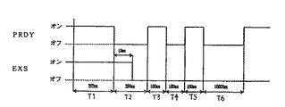
図19は、カードユニット31から払出制御基板144に入力される信号に異常が生じた場合に払出制御基板144により行なわれる異常時制御の動作を示すタイミングチャートである。図19においては、入力される信号に異常が生じた時点でPRDY信号およびEXS信号がオン状態であった場合が一例として示されている。
【0189】
図19を参照して、図18に示した払出制御基板144による監視時間A,C,E,Fのうちのいずれかが上限値を超えて正常ではないと判断された場合には、異常時制御として、次のように信号が制御される。その判断時点から所定の第1時間T1経過後に、PRDY信号が立下げられる。そして、PRDY信号の立下がりから第2時間T2経過後にPRDY信号が立上げられ、その立上がりから第3時間T3経過後にPRDY信号が立下げられ、その立下がりから第4時間T4経過後にPRDY信号が立上げられ、その立上がりから第5時間T5経過後にPRDY信号が立下げられ、その立下がりから第6時間T6経過後にPRDY信号が立上げられる。この実施の形態の場合、たとえば、T1は202ms、T2は200ms、T3,T4,T5は100ms、T6は10002msである。このようにカードユニット31から払出制御基板144に入力される信号に異常が生じた場合に、このようなPRDY信号が前述したような変化をすることにより、通信状態に異常が生じたことを信号の状態により確認することができる。
【0190】
次に、払出制御基板144により制御される賞球の払出しの基本的動作を説明する。図20は、賞球の払出しの基本的動作を示すタイミングチャートである。図20においては、払出し動作を説明するために、払出モータ118の動作状態(回転,停止)が示されている。
【0191】
ここで、払出制御基板144においては、前述したRAMにおいて、賞球の未払出し個数が更新可能に記憶される。賞球の未払出し個数は、RAMに設けられた賞球の未払出し個数カウンタにおいてカウンタ値を加減算することにより更新される。この賞球の未払出し個数は、賞球払出個数コマンドを受けるごとにコマンドにより示される払出個数分加算されることにより加算更新され、賞球個数カウントスイッチ120により賞球の払出が検出されるごとに「1」づつ減算更新される。前述したように、玉払出装置116による玉の最大払出個数は、25個であり、1つの入賞に対して払出される賞球の個数(13個または5個)よりも多い数に設定されている。つまり、たとえば、1つの入賞に応じた賞球の払出しがまだ完了しないような短時間に多数の入賞が発生した場合のように、所定期間内に複数の入賞があり、その複数の入賞に応じた賞球を払出す制御を行なう場合に、1入賞に応じた賞球の払出数ごとに玉払出装置116の払出モータ118の払出動作を区切ることなく、1入賞に応じた賞球の払出数よりも多い所定払出数(25個)の賞球を連続的に払出す制御が行なわれる。
【0192】
図20を参照して、賞球の払出しが行なわれる時において、賞球の未払出し個数が最大払出個数(25個)以下の場合は、未払出し個数に応じた回転量で払出モータ118が回転動作されることにより、1回の払出動作において、未払出し個数分の賞球がすべて払出される。また、賞球の払出しが行なわれる時において、未払出し個数が最大払出個数(25個)よりも多い場合、すなわち、未払出し個数が26個以上の場合は、払出モータ118の最初の1回の払出動作(回転動作)において、最大払出個数(25個)分の賞球が払出され、その残りの未払出し個数(残数)は、次回以降の回の払出動作(回転動作)により払出される。次回以降の払出動作においては、1回で25個の払出しを上限として、残りの未払出し個数払出個数分の賞球が払出され、残数がある場合は、またその次の回の払出動作により行なわれる。つまり、未払出し個数が最大払出個数(25個)よりも多い場合は、未払出し個数が「0」になるまで、最大払出個数(25個)を払出上限数とした賞球の払出しが繰返し行なわれるのである。
【0193】
以上のような最大払出個数よりも多い未払出し個数を払出す場合には、前回の払出しにおける払出モータの停止時から所定時間T7のインターバル時間経過後に次回の払出モータの回転動作が開始される。この実施の形態の場合のT7は、たとえば302msである。
【0194】
次に、賞球の払出動作中に払出し停止コマンドを払出制御基板144が受信した場合に、払出制御基板144により行なわれる動作制御を説明する。図21は、賞球の払出動作中に払出し停止コマンドを払出制御基板144が受信した場合の制御動作を示すタイミングチャートである。図21においては、動作状態を説明するために、図20の場合と同様に払出モータ118の動作状態(回転,停止)が示されている。ここで、払出し停止コマンドは、球切れスイッチ115により球切れが検出された場合、または、満タンスイッチ129により下皿27の満タンが検出された場合、すなわち、玉の払出し動作が正常に行なえない場合に、主基板151から出力される。
【0195】
図21を参照して、払出モータ118が回転動作中にあり、賞球の払出しが行なわれている途中(払出モータ118の1回の払出動作において払出すべき未払出し個数がまだ残っている払出途中状態)において、払出し停止コマンドを払出制御基板144が受信した場合は、その回の払出動作において払出すべき未払出し個数の残数の払出動作が終了した後、払出モータ118が停止され、払出動作が終了される。つまり、このような場合には、1回の払出動作が終了するまで払出動作が継続され、その1回の払出動作が終了した後に、払出動作が停止されるのである。
【0196】
次に、賞球の払出動作中に払出し停止コマンドを払出制御基板144が受信した場合に、図21に示されたような払出し停止コマンドに応じた停止状態において払出し停止解除コマンドを受信した場合に払出制御基板144により行なわれる動作制御を説明する。図22は、払出し停止コマンドに応じた停止状態において払出し停止解除コマンドを払出制御基板144が受信した場合の動作を示すタイミングチャートである。図22においては、動作状態を説明するために、図21の場合と同様に払出モータ118の動作状態(回転,停止)が示されている。ここで、払出し停止解除コマンドは、球切れの解消等の所定の払出し停止解除条件が成立した場合に、主基板151から出力される。
【0197】
図22を参照して、払出し停止コマンドに応じて払出モータ118が停止状態にあり、まだ未払出し個数が「1」以上である状態(未払出し個数の残数がある場合)において、払出し停止解除コマンドを受信した場合は、その受信時点から所定時間T8のインターバル時間の経過後に、払出モータの回転動作が開始させられる。これにより、未払出し個数がある状態で払出し停止解除コマンドを受けた場合には、一定のインバータバル期間(T8)を経て払出動作が再開される。一方、払出し停止解除コマンドを受信した時点で未払出し個数が「0」である場合には、図22に示されたような払出動作の再開は行なわれない。この実施の形態の場合のT8は、たとえば2002msである。
【0198】
このように、未払出し個数がある状態で払出し停止解除コマンドを受けた場合には、払出動作が再開されることにより、パチンコ遊技機1の都合による払出停止後において、遊技者への未払出し個数の払出しを補償することができ、遊技者と遊技場とのトラブルの発生を防ぐことができる。さらに、そのような場合の払出動作の再開が直ちに行なわれずに、インターバル期間をおいて行なわれることにより、たとえば、パチンコ遊技機1において球切れ状態に近い状態の玉の保有個数で球切れが解消された状態(球切れスイッチ115が玉を検出したこと)のように払出し停止条件が十分に解消できていない状態における払出動作の再開を避けることが可能になるため、払出動作の再開直後に、再度払出し停止状態が生じてしまうのを防ぐことができる。
【0199】
次に、賞球の払出動作中にカードユニット31から球貸しの要求を受けた場合に、払出制御基板144により行なわれる動作制御を説明する。図23は、賞球の払出動作中にカードユニット31から払出制御基板144が球貸しの要求を受けた場合の制御動作を示すタイミングチャートである。
【0200】
図23においては、BRDY信号、BRQ信号、EXS信号、払出経路(球貸し経路,賞球経路)、払出モータ(回転,停止)の状態が示されている。ここでの払出経路とは、通路切換弁250の状態により玉が払出されるように選択された玉の通路を示しており、球貸し経路が球貸し通路203cに該当し、賞球経路が賞球通路203dに該当している。この図23の場合、賞球経路の状態は、前述した通路切換ソレノイド117のソレノイド制御信号を用いて示されている。すなわち、図中では、経路の切換えが瞬時に行なわれているように示されているが、これは、あくまでもソレノイド制御信号(球貸し通路203cに切換える場合に励磁レベルになり、賞球通路203dに切換える場合に非励磁レベルになる信号)の状態が示されたものであり、実際の通路切換弁250は、図中の切換え状態よりも遅延して切換わる。
【0201】
図23を参照して、払出モータ118が回転動作中にあり、賞球の払出しが行なわれている途中(払出モータ118の1回の払出動作において払出すべき未払出し個数がまだ残っている払出途中状態)において、BRDY信号を払出制御基板144が受信した場合(BRDY信号が立上がった場合)は、その回の払出動作において払出すべき未払出し個数の残数の払出動作が終了した後、払出モータ118が停止され、払出動作が停止される。つまり、このような場合には、1回の払出動作が終了するまで払出動作が継続され、その1回の払出動作が終了した後に、払出動作が停止されるのである。
【0202】
そして、払出モータ118の停止時から所定時間T9が経過した後に、EXS信号が立上げられる。このように所定時間T9の経過を待つのは、最後にスプロケット205から払出された賞球が賞球個数カウントスイッチ120に検出されるまでに要する時間を待たなければ、そのような最後の賞球が正しく検出されない場合があるからである。したがって、所定時間T9は、最後にスプロケット205から払出された賞球が賞球個数カウントスイッチ120に検出されるに十分な時間に設定されている。このため、このような所定時間T9の経過を待つことにより、賞球の払出しから貸玉の払出しに切換わる場合における玉の誤検出を防ぐことができる。
【0203】
EXS信号が立上げられると、それに応じて、BRQ信号が立下げられる。そして、このようにBRQ信号が立下がった後、それに応じて、通路切換ソレノイド117が励磁状態にされて通路切換弁250の切換え動作が開始される。これにより、賞球通路203dから球貸し通路203cへの払出通路の切換えが開始される。そして、払出通路の切換開始時から所定時間T10の経過を待って、払出モータ118の回転動作が開始され、球貸しのための払出動作が開始される。このように所定時間T10の経過を待つのは、通路切換弁250による払出通路の切換えが瞬時的に行なわれるものではないので、通路切換弁250の切換え動作が終了するまでに要する時間を待たなければ、払出された玉が通路切換弁250と通路との間に挟まってしまう等の不具合が生じる場合があるからである。したがって、所定時間T10は、通路切換弁250による賞球通路203dから球貸し通路203cへの切換え動作が十分に終了し得る時間に設定されている。このため、このような所定時間T10の経過を待つことにより、玉の払出通路が切換わる場合における玉の挟み込みを防ぐことができるとともに、通路切換弁250による玉通路の切換えが完了したことにより確実な貸玉の払出しが可能になった状態で払出モータを駆動することができる。
【0204】
このように、払出制御用のマイクロコンピュータ144Mが貸玉の払出しを要求する信号(BRDY信号)を受けた場合、マイクロコンピュータ144Mは、それにしたがって、貸玉を払出す制御を行なう。このような貸玉の払出制御は、払出制御用のマイクロコンピュータ144Mが、カードユニット31からカード残高を特定可能な情報の入力を受けずに行なう。
【0205】
次に、図23に示されたような球貸し要求に応じた貸玉の払出し動作の終了後に払出制御基板144により行なわれる動作制御を説明する。
【0206】
図24は、賞球の払出途中で球貸し要求を受けた場合における球貸し動作終了後の動作を示すタイミングチャートである。図24においては、動作状態を説明するために、図23の場合と同様の種類の信号等が示されている。
【0207】
図24を参照して、賞球の払出途中で受けた球貸し要求に応じて球貸しが行なわれた後、その球貸しのための払出モータ118の払出動作が停止すると、その停止時から所定時間T11が経過した後に、通路切換弁250により払出通路を球貸し通路203cから賞球通路203dに切換える動作が開始される。このように所定時間T11の経過を待つのは、最後にスプロケット305から払出された貸玉が球貸し個数カウントスイッチ119に検出されるまでに要する時間を待たなければ、そのような最後の貸玉が正しく検出されない場合があるからである。したがって、所定時間T11は、最後にスプロケット305から払出された賞球が球貸し個数カウントスイッチ119に検出されるに十分な時間に設定されている。このため、このような所定時間T11の経過を待つことにより、貸玉の払出しから賞球の払出しに切換わる場合における玉の誤検出を防ぐことができる。この実施の形態の場合の所定時間T11は、前述した賞球の払出しから貸玉の払出しに切換わる場合における玉の誤検出を防ぐための所定時間T9よりも長い時間に設定される。これは、スプロケット305による玉の払出位置から球貸し個数カウントスイッチ119までの通路の長さ(行程)が、スプロケット305による玉の払出位置から賞球個数カウントスイッチ120までの通路の長さ(行程)よりも長いからである。
【0208】
通路切換弁250により球貸し通路203cから賞球通路203dへの払出通路の切換え動作が開始されると、その開始時から所定時間T12の経過を待って、EXS信号が立下げられる。このように所定時間T12の経過を待つのは、通路切換弁250による払出通路の切換えは、瞬時的に行なわれるものではないので、通路切換弁250の切換え動作が終了するまでに要する時間を待つためである。したがって、所定時間T12は、通路切換弁250による球貸し通路203cから賞球通路203dへの切換え動作が十分に終了し得る時間に設定されている。このため、このような所定時間T12の経過を待つことにより、通路切換弁250による玉通路の切換えが完了しことにより確実な賞球の払出しが可能になった状態で、EXS信号を立下げることができる。
【0209】
そして、前述したような球貸し要求を受けた時点で次回の払出動作における賞球の未払出し個数があった場合には、その次回分における未払出し個数の賞球の払出しを行なうために、払出モータ118の回転動作が開始される。一方、そのような次回払出し分の未払出し個数がない場合には、そのような払出動作は行なわれない。
【0210】
なお、図24においては、次回分における未払出し個数がある場合を示したが、ない場合であっても、貸玉の払出動作が終了すると、図24に示したように払出通路を球貸し通路203cから賞球通路203dに切換え、賞球払出待機状態になる。つまり、払出要求がないときは賞球通路203dを玉が通過するようになっているのである。また、図23,図24は、1回(100円分=玉25個)の球貸しを例に挙げて説明しているが、図18のように複数回(2回)の球貸し(200円分を100円分2回に分けて球貸しをする場合)の場合も、その払出動作1回ごとに通路切換動作(1回分の払出動作を行なう場合に、払出通路を賞球通路203dから球貸し通路203cに切換え、1回分の払出動作が終了すると払出通路を球貸し通路203cから賞球通路203dに切換える動作)を行なう。つまり、複数回の球貸しの場合は、前述した1回分の通路切換動作が複数回繰返し行なわれるのである。このようにすることで、図23,図24に示した一連の動作プログラムを複数回行なうようにすればいいので、プログラムの簡易化が図れ、プログラム容量を縮小できる。
【0211】
次に、払出制御基板144により制御される貸玉の払出しの基本的動作を説明する。図25は、貸玉の払出しの基本的動作を示すタイミングチャートである。図25においては、貸玉の払出し動作を説明するために、図23の場合と同様の種類の信号等が示されている。
【0212】
前述したように、払出制御基板144においては、前述したRAMにおいて、貸玉の未払出し個数が更新可能に記憶されている。貸玉の未払出し個数は、RAMに設けられた貸玉の未払出し個数カウンタにおいてカウンタ値を加減算することにより更新される。この貸玉の未払出し個数は、BRQ信号を受けるごとに最大払出個数分の貸玉の払出数が加算されることにより加算更新され、球貸し個数カウントスイッチ119により貸玉の払出が検出されるごとに「1」ずつ減算更新される。この実施の形態の場合、最大払出個数は、前述したように25個である。
【0213】
図25を参照して、貸玉の払出しが行なわれる時においては、図18に示されたような順序でBRQ信号が立下がってから所定時間T29の経過後、通路切換弁250の切換え動作が開始され、これにより、賞球通路203dから球貸し通路203cへの払出通路の切換えが開始される。この実施の形態の場合、所定時間T29は、2msに設定されている。
【0214】
そして、払出通路の切換開始時から前述した所定時間T10の経過を待って、払出モータ118の回転動作が開始され、球貸しのための払出動作が開始される。このような払出モータ118の回転動作により、1回の払出し動作で最大払出個数(25個)分の貸玉が払出される。そして、払出モータ118による1回の払出し動作が停止すると、その停止時から前述した所定時間T11が経過した後に、通路切換弁250により払出通路を球貸し通路203cから賞球通路203dに切換える動作が開始される。
【0215】
通路切換弁250により球貸し通路203cから賞球通路203dへの払出通路の切換え動作が開始されると、貸玉の未払出し個数が「0」になっていることを条件として、切換え動作開始時から前述した所定時間T12の経過を待って、EXS信号が立下げられる。そして、球貸し要求操作に応じた貸玉の払出しが終了すると、BRDY信号が立下げられる。
【0216】
なお、図25においては、1回(100円分=玉25個)の球貸しを例に挙げて説明しているが、図18のように複数回(2回)の球貸し(200円分を100円分2回に分けて球貸しをする場合)の場合は、前述したように、その払出動作1回ごとに払出通路の切換え動作(1回分の払出動作を行なう場合に、払出通路を賞球通路203dから球貸し通路203cに切換え、1回分の払出動作が終了すると払出通路を球貸し通路203cから賞球通路203dに切換える動作)を行なう。つまり、複数回の球貸しの場合は、たとえば500円分の球貸しの場合は5回分というように、前述した1回分の通路切換動作が複数回分繰返し行なわれるのである。
【0217】
次に、1回の貸玉の払出動作において払出された玉の個数が最大払出個数に満たなかった場合に、払出制御基板144により行なわれる制御動作を説明する。図26は、1回の貸玉の払出動作において払出された玉の個数が最大払出個数に満たなかった場合に、払出制御基板144により行なわれる制御動作を示すタイミングチャートである。図26においては、EXS信号、払出経路(球貸し経路,賞球経路)、払出モータ(回転,停止)の状態が示されている。また、図中のT10〜T12は、図25等に示されたT10〜T12と同様の時間である。
【0218】
図26を参照して、1回の貸玉の払出動作において払出された玉の個数が最大払出個数に満たなかった場合には、その貸玉の払出動作における払出モータ118の停止時から前述した所定時間T11経過後に、一旦払出経路が球貸し通路203cから賞球通路203dに切換える動作が開始される。そして、その切換え動作の開始時から前述した所定時間T12経過後に、再び、払出経路が賞球通路203dから球貸し通路203cに切換える動作が開始される。そして、その切換え動作の開始時から前述した所定時間T10経過後に、前回の1回の払出において払出せずに残った残数分の未払出し個数を払出すために、払出モータ118の動作が開始される。これにより、残数分の貸玉が払出される。そして、その払出動作における払出モータ118の停止時から前述した所定時間T11経過後に、払出経路が球貸し通路203cから賞球通路203dに切換える動作が開始される。そして、その切換え動作の開始時から前述した所定時間T12経過後に、EXS信号が立下げられる。このように、EXS信号は、未払出し個数分の貸玉の払出しが完了したことが確認された場合に立下げられるのである。
【0219】
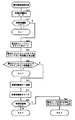
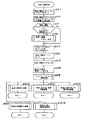
次に、主基板151のCPU151aにおいて実行される制御処理の内容を説明する。図27は、主基板151のCPU151aにおいて実行される制御処理のメイルーチンとしてのメイン処理を示すフローチャートである。
【0220】
ステップS(以下、単にSという)1〜S12により、制御処理の実行のための初期設定を行なう処理がなされる。S1により、割込みが禁止される。次に、S2により、割込み処理のモードを示す割込みモード2の設定が行なわれる。次に、S3により、スタックポインタの設定が行なわれる。次に、S4により、内蔵デバイスレジスタの設定が行なわれる。次に、S5により、CTCおよびPIOの設定が行なわれる。次に、S6により、RAMをアクセス可能にする設定が行なわれる。
【0221】
そして、S7により、主基板151のRAMにバックアップデータがないかどうか(記憶されていないかどうか)の判断がなされる。このバックアップデータは、前述したように、停電があった場合等の所定の場合に、電源基板137から電源断信号を受けたことに応じてRAMに記憶されるものである。
【0222】
S7によりバックアップデータがあると判断された場合は、S8に進み、記憶されているバックアップデータに基づいて、CPU151aにおいて実行される制御処理の状態を電源断前の状態に復旧させる処理がなされる。その後、このメイン処理が終了する。一方、S7によりバックアップデータがないと判断された場合は、S9に進み、主基板151のRAMの記憶データをクリアする処理がなされる。次に、S10により、サブ基板と呼ばれる図柄制御基板75、音声制御基板82、ランブ制御基板80、および、払出制御基板144をそれぞれ初期化する処理が行なわれる。次に、S11により、CTC割込みの設定が行なわれる。次に、S12により、割込みが許可される。
【0223】
次に、S13により、特別可変表示装置44の可変表示における停止図柄を決定する等のための表示用乱数を更新するための表示用乱数更新処理が行なわれる。このパチンコ遊技機1においては、特別可変表示装置44の可変表示における特別図柄の停止図柄が乱数(ランダムカウンタのカウンタ値)に基づいて決定される。このS13では、特別図柄のうちの一部の停止図柄を決定するための表示用乱数が更新される。
【0224】
S13の後、S14に進み、タイマ割込みがされていないかどうかの判断がなされる。主基板151においては、タイマ割込みをするための計時を行なうタイマが設けられており、そのタイマにより所定時間(たとえば、0.002S)が計時されるごとに、タイマ割込みがなされる。S14においては、タイマ割込みが行なわれるまで待機し、タイマ割込みが行なわれた場合に、S15に進む。したがって、S15〜S25のサブルーチン処理は、タイマ割込みが行なわれるごとに実行されることとなる。
【0225】
次に、S15により、ゲートスイッチ62、第1種始動口スイッチ60、特定領域スイッチ51、および、カウントスイッチ52等の状態を入力し、各入賞口や可変入賞球装置に対する入賞があったか否か等を判定するスイッチ処理が行なわれる。
次に、S16により、パチンコ遊技機1の内部に備えられている自己診断機能によって種々の異常診断をし、その結果に応じて必要ならば警報を発生させるためのエラー処理が行なわれる。次に、S17により、遊技制御に用いられる各種の判定用乱数を示す各ランダムカウンタを更新する乱数更新処理が行なわれる。
【0226】
次に、S18により、前述したS13と同様の表示図柄乱数更新処理が行なわれる。次に、S19により、特別図柄プロセス処理が行なわれる。特別図柄プロセス処理では、複数種類の処理のうちの1つが特別図柄プロセスフラグの値に従って選択されて実行される。そして、特別図柄プロセスフラグの値は、遊技状態に応じて各処理中において更新される。
【0227】
次に、S20により、普通図柄プロセス処理が行なわれる。普通図柄プロセス処理では、普通図柄表示器63を所定の制御順序で制御するための普通図柄プロセスフラグに従って該当する処理が選択されて実行される。そして、普通図柄プロセスフラグの値は、遊技状態に応じて各処理中に更新される。
【0228】
次に、S21により、特別図柄の可変表示を行なうためのコマンドとしての図柄制御信号を制御するための特別図柄コマンド制御処理が行なわれる。次に、S22により、普通図柄の可変表示を行なうためのコマンドとしての普通図柄制御信号を制御するための普通図柄コマンド制御処理が行なわれる。
【0229】
次に、S23により、盤用外部端子基板132への外部出力情報の送信等の基板外部への各種情報の出力を行なう情報出力処理が行なわれる。
【0230】
次に、S24により、各種ソレノイド50,53,59を駆動制御するための信号を基板に出力するソレノイド出力処理が行なわれる。次に、S25により、次に、入賞球信号に応じて賞球を払出すための賞球処理が行なわれる。
【0231】
S25の実行後は、前述したS13に戻り、次のタイマ割込みのタイミングまで、S15〜S25のサブルーチンの実行が待たれる。
【0232】
次に、主基板151のCPU151aにおいて実行されるタイマ割込み処理について説明する。図28は、主基板151のCPU151aにおいて実行されるタイマ割込み処理を示すフローチャートである。
【0233】
CPU151aは、予め定められた計時用のカウンタを常時監視し、2msが経過するごとに、タイマ割込みを行なうために、タイマ割込み処理を実行する。タイマ割込み処理においては、まず、ステップSB(以下、単にSBという)1により、タイマ割込みがあったことを示すデータとして、タイマ割込みありを示すデータを設定する処理がなされる。これにより、前述したメイン処理のS14において、タイマ割込みありと判断される。次に、SB2により、次のタイマ割込みを許可する処理がなされる。その後、このタイマ割込み処理が終了する。
【0234】
次に、前述したメイン処理のS25による賞球処理の内容を説明する。図29は、主基板151のCPU151aにおいて実行される賞球処理を示すフローチャートである。
【0235】
まず、ステップSC(以下、単にSCという)1により、満タンチェック処理が行なわれる。この満タンチェック処理においては、満タンスイッチ129の状態がチェックされ、満タンスイッチ129が100ms以上オン状態(満タン検出状態)になった場合に、満タンスイッチ129により満タン状態が検出されたと判断される。
【0236】
次に、ステップSC2により、球切れチェック処理が行なわれる。この球切れチェック処理においては、球切れスイッチ115の状態がチェックされ、球切れスイッチ115が100ms以上オン状態(球切れ検出状態)になった場合に、球切れスイッチ115により球切れ状態が検出されたと判断される。
【0237】
次に、ステップSC3により、賞球停止処理が行なわれる。この賞球停止処理においては、前述した満タン状態または球切れ状態が検出された場合に、賞球停止停止コマンドを出力するための処理が行なわれる。
【0238】
次に、ステップSC4により、賞球個数コマンド格納処理が行なわれる。この賞球個数コマンド格納処理においては、入賞があった場合に、その入賞の種別に応じた賞球個数を示すコマンドを格納する処理が行なわれる。次に、ステップSC5により、賞球個数コマンド設定処理が行なわれる。この賞球個数コマンド設定処理においては、賞球個数コマンド格納処理において格納されたコマンドを出力するために設定する処理がなされる。
【0239】
次に、ステップSC6により、賞球個数コマンド設定処理において設定されて賞球制御信号として出力される賞球個数を、まだ払出しが終了していない賞球数の総和を示す総賞球個数のデータに加算して、加算後の総賞球個数を記憶する処理が行なわれる。次に、SC7により、賞球個数カウントスイッチ120により賞球の検出信号を受けるごとに、前述したSC6で求められた総賞球個数を減算更新する処理が行なわれる。このようなSC6およびSC7により、主基板151のCPU151aにおいて、賞球の払出要求しを要求したがまだ払出されていない総賞球個数(未払出し個数)を正確に把握することができる。
【0240】
次に、前述した賞球処理のSC6による賞球個数加算処理の内容を説明する。図30は、賞球個数加算処理を示すフローチャートである。まず、ステップSH(以下、単にSHという)1により、賞球個数コマンド設定処理において設定されて賞球制御信号として出力される賞球個数のデータの格納領域から賞球個数のデータをRAMにおける総賞球個数演算領域にロードする処理がなされる。
【0241】
次に、SH2に進み、SH1においてロードした賞球個数の値が「0」であるか否かの判断がされる。SH2により「0」であると判断された場合、すなわち、賞球個数を指定した賞球制御信号が出力されない場合には、この賞球個数加算処理が終了する。一方、SH2により「0」ではないと判断された場合、すなわち、賞球個数を指定した賞球制御信号が出力される場合には、SH3に進み、総賞球個数のデータの記憶領域から現在の総賞球個数のデータをRAMにおける総賞球個数演算領域にロードする処理がなされる。
【0242】
次に、SH4に進み、SH3によりロードした総賞球個数の値とSH1によりロードした賞球個数の値とを加算し、加算結果を現在の総賞球個数として得る処理がされる。そして、SH5に進み、SH4により得られた加算後のデータを現在の総賞球個数として前述の総賞球個数データの格納領域にストアする処理がされる。これにより、総賞球個数の値は、賞球個数を指定した賞球制御信号が出力されるごとに更新される。次に、SH6に進み、前述したSC5の賞球個数コマンド設定処理により設定された賞球の払出しを指定するコマンドを出力データとしてセットし、賞球制御信号として出力する処理がされる。
【0243】
次に、SH7に進み、賞球ランプ10が点灯中であるか否かの判断がされる。、すなわち、未払出個数があることに応じて賞球ランプ10が点灯しているか否かの判断がされる。賞球ランプ10が点灯中である場合には、賞球の未払出し個数があることを示すためには、未払出し個数があることを示す賞球ランプ10の点灯状態を維持するだけでよいので、この賞球個数加算処理が終了する。一方、賞球ランプ10が消灯している場合には、未払出し個数があることを示すために賞球ランプ10を点灯させる必要があるため、SH8に進み、賞球ランプ10の点灯を指定するコマンド(ランプ制御信号)を出力データとしてセットし、ランプ制御信号として出力する処理がされる。その後、この賞球個数加算処理が終了する。
【0244】
このように、主基板151側においては、新たな賞球の払出しを指令するごとに総賞球個数の値を加算更新することにより、未払出し個数を総賞球個数として管理しており、未払出し個数がある場合には賞球ランプ10を点灯させる制御が行なわれる。
【0245】
次に、前述した賞球処理のSC7による賞球個数減算処理の内容を説明する。図31は、賞球個数減算処理を示すフローチャートである。まず、ステップSH(以下、単にSLという)1により、RAMにおける総賞球個数のデータの記憶領域から現在の総賞球個数のデータをRAMにおける総賞球個数演算領域にロードする処理がなされる。
【0246】
次に、SL2に進み、SL1においてロードした総賞球個数の値が「0」であるか否かの判断がされる。SL2により「0」であると判断された場合、すなわち、未払出し個数がない場合には、この賞球個数加算処理が終了する。一方、SL2により「0」ではないと判断された場合、すなわち、未払出し個数がある場合には、SL3に進み、賞球個数カウントスイッチタイマの値をRAMにおける賞球個数カウントスイッチタイマ判定用領域にロードする処理がなされる。この賞球個数カウントスイッチタイマは、賞球個数カウントスイッチ119がオン状態(玉を検出している状態)となるごとに、その継続時間を計時するタイマであり、そのタイマ値がRAMの当該タイマ用領域に格納されている。このため、SL3では、タイマ値をロードしてきて、この賞球個数減算処理のために使用するのである。
【0247】
次に、SL4により、SL3によってロードした賞球個数カウントスイッチタイマのタイマ値と、予め定められたスイッチオン判定値とを比較する処理がなされる。ここで、スイッチオン判定値は、賞球個数カウントスイッチ120が正常な状態で玉を検出したと認められるオン状態の継続時間である。このスイッチオン判定値の時間以上継続して賞球個数カウントスイッチ120がオン状態となっている場合には、賞球個数カウントスイッチ120が正常な状態で玉を検出したと認められる。
【0248】
次に、SL5により、SL4によって比較された賞球個数カウントスイッチタイマのタイマ値がスイッチオン判定値と一致する値に達したか否かの判断がなされる。SL5により一致する値に達していないと判断された場合は、ノイズ等による誤検出のおそれがあるため、この状態では正常な状態で玉を検出したと認めず、そのままこの賞球個数減算処理が終了する。一方、SL5により一致する値に達したと判断された場合は、賞球個数カウントスイッチ120が正常な状態で玉を検出したと認め、SL6に進み、SL1によりロードした総賞球個数の値が「1」だけ減算更新される。これにより、賞球の払出し検出に応じて、賞球の未払出し個数が減じられるのである。次に、SL7に進み、SL6による減算の結果得られた総賞球個数を前述の総賞球個数データの格納領域にストアする処理がされる。これにより、総賞球個数の値は、賞球個数カウントスイッチ120により賞球が検出されるごとに更新される。
【0249】
次に、SL8に進み、総賞球個数が「0」であるか否かの判断がなされる。総賞球個数が「0」ではないと判断された場合、すなわち、未払出個数がある場合には、そのままこの賞球個数減算処理が終了する。つまり、この段階では、賞球ランプ10が点灯中であり、未払出個数がある場合は、賞球ランプ10の点灯を継続しなければならないので、そのまま処理が終了するのである。一方、総賞球個数が「0」であると判断された場合、すなわち、未払出個数がなくなった場合は、SL9に進み、賞球ランプ10の消灯を指定するコマンド(ランプ制御信号)を出力データとしてセットし、ランプ制御信号として出力する処理がなされる。つまり、この段階では、賞球ランプ10が点灯中であり、未払出個数がなくなった場合は、賞球ランプ10を消灯させなければならないので、SL8が実行されるのである。SL9の後、この賞球個数減算処理が終了する。
【0250】
このように、主基板151側においては、賞球個数カウントスイッチ120により賞球の払出検出がされるごとに総賞球個数の値を減算更新することにより、賞球個数加算処理とあわせて、前述した未払出し個数を総賞球個数として管理しており、未払出し個数がなくなった場合には賞球ランプ10を消灯させる制御が行なわれる。
【0251】
次に、図柄制御信号、音声制御信号、賞球制御信号およびランプ制御信号のそれぞれのコマンドを送信する場合に実行されるコマンド送信処理の内容を説明する。図32は主基板151のCPU151aにおいて実行されるコマンド送信処理を示すフローチャートである。このコマンド送信処理は、主基板151から各サブ基板(図柄制御基板75、音声制御基板82、ランブ制御基板80、および、払出制御基板144)に制御信号として送信するべくセットしたコマンドを送信するための処理であり、たとえば、前述したSH6,SH8,SL9のような各制御基板に送信するコマンドをセットする各種処理の実行にともなって起動されるサブルーチンであり、たとえば、前述したSH6,SH8,SL9の場合は、各ステップにおいて、このコマンド送信処理が呼出されて実行されることにより、コマンドが送信されることとなる。したがって、コマンド送信処理は、前述したメイン処理のうちの各コマンドの送信に関連する処理において実行されるものであり、図柄制御信号、音声制御信号、ランプ制御信号、および、賞球制御信号の出力のために共通利用される。
【0252】
図32を参照して、まず、ステップSD(以下、単にSDという)1により、INT信号を出力するためのデータを比較値にセットする処理がなされる。次に、SD2により、送信回数(4)を処理数にセットする処理がなされる。この送信回数は、コマンド送信処理の1回の実行中にコマンドの送信先を見つけ出す処理を繰返し行なう回数であり、後述するように前述した4つのサブ基板のすべてをコマンドの送信先としてチェックできるように「4」にセットされる。
【0253】
次に、SD3により、コマンドを出力する出力ポートのアドレスを指定するIOアドレスをポート1のアドレスにセットする処理がなされる。ここで、たとえば、ポート1が図柄制御基板75、ポート2が音声制御基板82、ポート3がランブ制御基板80、ポート4が払出制御基板144というように、出力ポートが各基板に対応しており、出力ポートのアドレスを、コマンドの送信を行なうIOアドレスとしてセットすることにより、コマンドの送信先のサブ基板が選択される。
【0254】
次に、SD4により、比較値を右にシフトする処理がなされる。これにより、比較値が、IOアドレスにより特定される出力ポートにセットされている出力データと比較可能な値に決められる。このように決められた比較値のデータと、IOアドレスにより特定される出力ポートにセットされている出力データとが、比較され、比較対象の出力ポートにコマンドの出力データがセットされている場合には、これらの値が一致し、キャリフラグがセットされる。つまり、出力するコマンドデータがセットされている出力ポートは、対応する基板へコマンドデータを出力することがすでに決められていることに応じてデータがセットされているため、各出力ポートにデータがセットされているかどうかを確認することにより、対応する基板へコマンドデータを出力することが認識されるのである。
【0255】
次に、SD5により、キャリフラグがセットされたか否かの判断がなされる。SD5によりキャリフラグがセットされていると判断された場合は、SD6により、該当するIOアドレスに、送信するコマンドを出力する処理がなされる。これにより、コマンドが出力される。その後、SD7に進む。一方、キャリフラグがセットされていないと判断された場合は、そのままSD7に進む。
【0256】
SD7では、IOアドレスを1加算する処理がなされる。これにより、次のループで出力データの状態を比較する出力ポートが次の処理順序の出力ポートに切換えられる。次に、SD8に進み、SD2によりセットした処理数を「1」だけ減算し、減算更新された後の処理数が0以外になっているか否かの判断がなされる。SD8により減算更新された後の処理数が0になっていない場合には、前述したSD4に戻り、次のチェック順序の出力ポートに関して、前述したようなコマンド出力先のチェックが行なわれる。一方、SD8により減算更新された後の処理数が0になった場合には、前述したSD9に進む。
【0257】
SD9では、出力するINT信号のデータをセットする処理がなされる。そして、SD10により、SD9においてセットされたINT信号のデータを、INT信号の出力用のポートである出力ポート0に出力する処理がなされる。これにより、INT信号が出力される(立上げられる)。次に、SD11により、ウエイトカウンタをセットする処理がなされる。ここで、ウエイトカウンタは、待機時間をカウントするためのカウンタであり、この段階ではINT信号の出力期間を監視するために用いられ、「5」にセットされる。
【0258】
次に、SD12に進み、ウエイトカウンタのカウンタ値を「1」だけ減算更新する処理がなされ、減算更新された後のカウンタ値が0以外になっているか否かの判断がなされる。SD12により減算更新された後のカウンタ値が0になっていない場合には、SD12の処理が繰返される。一方、SD12により減算更新された後の処理数が0になった場合には、SD13に進み、クリアデータをセットする処理がなされた後、そのセットされたクリアデータをSD14により出力ポート0に出力する処理がなされる。これにより、INT信号の出力用のデータがクリアされ、INT信号が停止される(立下げられる)。このように、INT信号は、立上がった後、ウエイトカウンタで5が計数される時間だけ出力レベルが継続された後、立下げられる。
【0259】
次に、SD15により、ウエイトカウンタをセットする処理がなされる。この段階でのウエイトカウンタは、このコマンド送信処理の終了期間を監視するために用いられ、「5」にセットされる。次に、SD16に進み、ウエイトカウンタのカウンタ値を「1」だけ減算更新する処理がなされ、減算更新された後のカウンタ値が0以外になっているか否かの判断がなされる。SD16により減算更新された後のカウンタ値が0になっていない場合には、SD16の処理が繰返される。一方、SD12により減算更新された後の処理数が0になった場合には、このコマンド送信処理が終了する。
【0260】
以上のようなコマンド送信処理によれば、前述したサブ基板に対して出力するコマンドがセットされた場合に、1つの制御ルーチンの実行により、出力先のサブ基板を選択することにより、このコマンド送信処理の実行により、どのサブ基板に対しても、コマンドを送信することができる。
【0261】
次に、払出制御基板144のCPUにおいて実行される制御処理の内容を説明する。図33は、払出制御基板144のCPU144jにおいて実行される制御処理のメイルーチンとしてのメイン処理を示すフローチャートである。
【0262】
ステップSE(以下、単にSEという)1〜SE12により、制御処理の実行のための初期設定を行なう処理がなされる。SE1により、割込みが禁止される。次に、SE2により、割込み処理のモードを示す割込みモード2の設定が行なわれる。次に、SE3により、スタックポインタの設定が行なわれる。次に、SE4により、内蔵デバイスレジスタの設定が行なわれる。次に、SE5により、CTCベクタの設定が行なわれる。次に、SE6により、未使用CTCおよびPIOの設定が行なわれる。次に、SE7により、RAMをアクセス可能にする設定が行なわれる。
【0263】
そして、SE8により、RAMにバックアップデータがないかどうかないか(記憶されていないかどうか)の判断がなされる。このバックアップデータは、前述したように、停電があった場合等の所定の場合に、電源基板137から電源断信号を受けたことに応じてRAMに記憶されるものである。
【0264】
SE8によりバックアップデータがあると判断された場合は、SE9に進み、記憶されているバックアップデータに基づいて、払出制御基板144のCPUにおいて実行される制御処理の状態を電源断前の状態に復旧させる処理がなされる。その後、このメイン処理が終了する。一方、SE8によりバックアップデータがないと判断された場合は、SE10に進み、RAMの記憶データをクリアする処理がなされる。次に、SE11により、CTC割込みの設定が行なわれる。次に、SE12により、割込みが許可される。
【0265】
SE12の後、SE13に進み、タイマ割込みがされていないかどうかの判断がなされる。払出制御基板144においては、タイマ割込みをするための計時を行なうタイマが設けられており、そのタイマにより所定時間(たとえば、0.002sec)が計時されるごとに、タイマ割込みがなされる。SE13においては、タイマ割込みが行なわれるまで待機し、タイマ割込みが行なわれた場合に、SE14に進む。したがって、SE14〜SE23のサブルーチン処理は、タイマ割込みが行なわれるごとに実行されることとなる。
【0266】
SE14においては、スイッチ処理が実行される。このスイッチ処理においては、払出制御基板144に接続された各種スイッチ(球貸し個数カウントスイッチ119,賞球個数カウントスイッチ120等)の出力信号の状態をチェックし、スイッチが検出動作をしたか否か等が判定される。
【0267】
SE15においては、入力判定処理が実行される。この入力判定処理においては、主基板151からの賞球制御信号(コマンド,INT信号)の入力判定が行なわれ、INT信号の入力に応じてコマンドが受信される。SE16においては、コマンド解析実行処理が実行される。このコマンド解析実行処理においては、受信した賞球制御信号のコマンドの指令内容が解析される。払出制御基板144においては、この解析結果に基づいてコマンドの指令内容を認識し、コマンドにしたがった処理が行なわれる。
【0268】
SE17においては、払出し停止状態設定処理が実行される。この払出し停止状態設定処理においては、前述した払出停止コマンドにしたがって行なわれる玉の払出し停止状態が設定される。この処理においては、たとえば、前述した図15に示された払出し停止解除コマンドの受信後のインターバル時間としてのT8等が設定される。
【0269】
SE18においては、プリペイドカードユニット制御処理が実行される。このプリペイドカードユニット制御処理は、カードユニット31に関連する各種制御を行なう処理であって、前述した払出制御基板144とカードユニット31との間での信号の送受信処理等の球貸しに関する制御処理が行なわれる。
【0270】
SE19においては、球貸し制御処理が実行される。この球貸し制御処理においては、前述したような制御タイミングで貸玉を払出すための払出制御が行なわれる。この球貸し制御処理の処理内容は、図36を用いて後述する。SE20においては、賞球制御処理が実行される。この賞球制御処理においては、前述したような制御タイミングで賞球を払出すための払出制御が行なわれる。この賞球制御処理の処理内容は、図38を用いて後述する。SE21においては、払出モータ制御処理が実行される。この払出モータ制御処理においては、払出モータの駆動に関する制御が行なわれる。
【0271】
SE22においては、エラー処理が実行される。このエラー処理においては、カードユニット31の接続異常に関する処理、カードユニット31の制御異常に関する処理、発射制御信号の制御に関する処理、賞球個数カウントスイッチ120の球詰まりを監視する処理、球貸し個数カウントスイッチ119の球詰まりを監視する処理、賞球経路の異常に関する処理、球貸し経路の異常に関する処理、および、エラー情報の表示に関する処理等のエラー状態(異常状態)に関する各種処理が行なわれる。
【0272】
SE23においては、出力処理が実行される。この出力処理においては、払出制御基板144から各種信号、エラー情報を含む各種データを出力する処理がなされる。SE23の実行後は、前述したSE13に戻り、次のタイマ割込みのタイミングまで、SE14〜SE23のサブルーチンの実行が待たれる。
【0273】
次に、払出制御基板144のCPU144jにおいて実行されるコマンド割込み処理について説明する。図34は、払出制御基板144のCPU144jにおいて実行されるコマンド割込み処理を示すフローチャートである。
【0274】
CPU144jは、賞球制御信号INTを受けたか否かを常時監視し、賞球制御信号INTを受けた場合に、コマンド割込み処理を実行する。コマンド割込み処理においては、まず、ステップSG(以下、単にSGという)1により、コマンドデータ、すなわち、賞球制御信号CD0〜CD7を入力し、SG2により、そのコマンドデータを設定する(格納する)処理がなされる。次に、SG3により、次のコマンド割込みを許可する処理がなされる。その後、このコマンド割込み処理が終了する。
【0275】
次に、払出制御基板144のCPU144jにおいて実行されるタイマ割込み処理について説明する。図35は、払出制御基板144のCPU144jにおいて実行されるタイマ割込み処理を示すフローチャートである。
【0276】
CPU144jは、予め定められた計時用のカウンタを常時監視し、2msが経過するごとに、タイマ割込みを行なうために、タイマ割込み処理を実行する。タイマ割込み処理においては、まず、ステップSH(以下、単にSHという)1により、タイマ割込みがあったことを示すデータとして、タイマ割込みありを示すデータを設定する処理がなされる。これにより、図33に示したメイン処理のSE13において、タイマ割込みありと判断される。次に、SH2により、次のタイマ割込みを許可する処理がなされる。その後、このタイマ割込み処理が終了する。
【0277】
次に、前述したSE19の球貸し制御処理の処理内容を説明する。図36は、球貸し制御処理の処理内容を示すフローチャートである。
【0278】
図36を参照して、まず、ステップSM(以下、単にSMという)1により、球貸し個数カウントスイッチタイマの値をロードする処理がなされる。この球貸し個数カウントスイッチタイマは、球貸し個数カウントスイッチ119がオン状態(玉を検出している状態)となるごとに、その継続時間を計時するタイマであり、そのタイマ値がRAMに記憶される。このため、SM1では、タイマ値をロードしてきて、この球貸し制御処理のために使用するのである。
【0279】
次に、SM2により、SM1によってロードした球貸し個数カウントスイッチタイマのタイマ値と、予め定められたスイッチオン判定値とを比較する処理がなされる。ここで、スイッチオン判定値は、球貸し個数カウントスイッチ119が正常な状態で玉を検出したと認められるオン状態の継続時間である。このスイッチオン判定値に相当する時間以上の時間にわたり球貸し個数カウントスイッチ119が継続してオン状態となっている場合には、球貸し個数カウントスイッチ119が正常な状態で玉を検出したと認められる。
【0280】
次に、SM3により、SM2によって比較された球貸し個数カウントスイッチタイマのタイマ値がスイッチオン判定値と一致する値に達したか否かの判断がなされる。SM3により一致する値に達したと判断された場合は、球貸し個数カウントスイッチ119が正常な状態で玉を検出したと認め、SM4に進み、球貸し個数カウント処理が実行される。この球貸し個数カウント処理においては、前述した貸玉の未払出し個数の記憶値が「1」だけ減算更新される。これにより、貸玉の払出し検出に応じて、貸玉の未払出し個数が減じられるのである。SM4の内容については、図37を用いて後述する。SM4の後、SM5に進む。一方、SM3により一致する値に達していないと判断された場合は、ノイズ等による誤検出のおそれがあるため、正常な状態で玉を検出したと認めず、そのままSM5に進む。
【0281】
SM5では、モジュールブロックのアドレスをポインタにセットする処理がなされる。次に、SM6に進み、球貸し制御コードをロードする処理がなされる。この球貸し制御コードは、SM10〜SM14の処理のうちの実行させるべき制御処理を指定するためのコードデータであり、球貸し制御処理の進行に応じて変更され得る。次に、SM7に進み、SM7〜SM9が実行されることにより、SM6によりロードされた球貸し制御コードを、SM10〜SM14のうちのいずれかの処理を指定できる値にする処理がなされる。具体的に、SM7ではSM6によりロードされた球貸し制御コードを2倍する処理が行なわれ、SM8ではSM7により算出された球貸し制御コードを2倍する処理が行なわれ、SM9では2バイト・1バイト加算処理が行なわれる。
【0282】
SM9の後、SM10〜SM14の処理のうち、SM6〜SM9の処理により得られた球貸し制御コードに対応する制御コードが指定された処理が実行され、その後、この球貸し制御処理が終了する。具体的に、SM10は、球貸し開始待ち処理である。この球貸し開始待ち処理においては、前述したような球貸し要求があるか否かを判定し、球貸し要求がある場合に、貸玉の払出数の設定、球貸し制御に用いる球貸し制御タイマの設定、および、次に実行する球貸し払出し経路切替え処理の制御コードの指定等が行なわれる。
【0283】
SM11は、球貸し払出し経路切替え処理である。この球貸し払出し経路切替え処理においては、まず、通路切換弁250を賞球通路203dから球貸し通路203cに切換える切換え動作を実行させるためにソレノイド制御信号を励磁レベルにして通路切換ソレノイド117を切換え動作させる。これにより、賞球通路203dから球貸し通路203cへの玉の払出通路の切換えが開始される。また、前述した球貸し開始待ち処理において設定された球貸し制御タイマがタイムアップするまで待ち、タイムアップした後に、払出モータ118を制御するための払出モータ制御コードを設定するとともに、次に実行する球貸し時払出モータ停止待ち処理の制御コードの指定等が行なわれる。これにより、前述した図25に示された時間T10の経過後に、払出モータの払出動作を開始させる制御が行なわれる。
【0284】
SM12は、球貸し時払出モータ停止待ち処理である。この球貸し時払出モータ停止待ち処理においては、払出モータ118の払出動作中において球貸し個数カウントスイッチ119により検出された玉の個数をチェックし、払出モータ118の停止後、球貸し制御タイマを前述した図25に示した所定時間T11に設定するとともに、次に実行する球貸し球通過待ち処理の制御コードの指定等が行なわれる。
【0285】
SM13は、球貸し球通過待ち処理である。この球貸し球通過待ち処理においては、まず、払出モータ118の払出動作停止後において球貸し個数カウントスイッチ119により検出された玉の個数をチェックし、貸玉の未払出し個数が「0」になったか否かを判断する。また、球貸し時払出モータ停止待ち処理において設定された球貸し制御タイマがタイムアップするまで待ち、タイムアップした時点で、球貸し制御タイマを前述した図25に示した所定時間T12に設定するとともに、次に実行する賞球払出し経路切替え処理の制御コードの指定等が行なわれる。また、この段階で、払出モータ118の玉噛み等のエラーが生じた場合に、そのエラーに対応したエラー時処理を実行するための処理も行なわれる。
【0286】
SM14は、賞球払出し経路切替え処理である。この賞球払出し経路切替え処理においては、まず、通路切換弁250を球貸し通路203cから賞球通路203dに切換える切換え動作を実行させるためにソレノイド制御信号を非励磁レベルににして通路切換ソレノイド117を切換え動作させる。これにより、球貸し通路203cから賞球通路203dへの玉の払出通路の切換えが開始される。
【0287】
また、前述した球貸し球通過待ち処理において設定された球貸し制御タイマがタイムアップするまで待ち、タイムアップした後に、貸玉の未払出し個数が「0」であるか否かの判断がなされる。そして、貸玉の未払出し個数が「0」である場合は、前述したSM10の球貸し開始待ち処理を次回の処理時に実行するように制御コードの指定等が行なわれる。これより、この時点で貸玉の未払出し個数が「0」になった場合には、球貸し開始待ち状態に戻るのである。
【0288】
一方、貸玉の未払出し個数が「0」でない場合(「1」以上である場合)は、前述したSM11の球貸し払出し経路切替処理を次回の処理時に実行するように制御コードの指定等が行なわれる。これより、この時点で貸玉の未払出し個数が「0」になっていない場合には、残った未払出し個数を払出すために、球貸し払出し経路切替処理が再度実行され、その処理に続いて行なわれる前述した各処理の実行により、図26に示されるような貸玉の未払出し個数の残数の払出しが実行されるのである。
【0289】
以上のような球貸し制御処理の実行により、前述した各タイミングチャートにより示したような球貸しの制御が行なわれる。
【0290】
次に、前述した図36のSM4により実行される球貸し個数カウント処理の内容を説明する。図37は、球貸し個数カウント処理の内容を示すフローチャートである。
【0291】
まず、SG(以下、単にSGという)1により、RAMにおける貸玉未払出個数格納領域に格納されている貸玉未払出個数カウンタのカウンタ値をRAMにおける貸玉未払出個数の演算領域へロードする処理がなされる。
【0292】
次に、SG2に進み、SG1によりロードされた貸玉未払出個数カウンタ値により示される貸玉未払出個数が「0」であるか否かの判断がされる。SG2により貸玉未払出個数が「0」であると判断された場合は、この球貸し個数カウント処理が終了する。一方、SG2により貸玉未払出個数が「0」ではないと判断された場合は、SG3に進み、SG1によりロードされた貸玉未払出個数カウンタ値から「1」を減算更新する処理がなされる。次に、SG4に進み、SG3により減算更新された貸玉未払出個数カウンタ値を、前述した貸玉未払出個数格納領域にストアする処理がなされる。
【0293】
以上のような球貸し個数カウント処理によれば、球貸し個数カウントスイッチ119による貸玉の払出し検出に応じて、払出制御用のマイクロコンピュータ144Mが把握している貸玉未払出個数が減じられることとなる。
【0294】
次に、前述したSE20の賞球制御処理の処理内容を説明する。図38は、賞球制御処理の処理内容を示すフローチャートである。
【0295】
図38を参照して、まず、ステップSJ(以下、単にSJという)1により、賞球個数カウントスイッチタイマの値をロードする処理がなされる。この賞球個数カウントスイッチタイマは、賞球個数カウントスイッチ119がオン状態(玉を検出している状態)となるごとに、その継続時間を計時するタイマであり、そのタイマ値がRAMに記憶されている。このため、SJ1では、タイマ値をロードしてきて、この賞球制御処理のために使用するのである。
【0296】
次に、SJ2により、SJ1によってロードした賞球個数カウントスイッチタイマのタイマ値と、予め定められたスイッチオン判定値とを比較する処理がなされる。ここで、スイッチオン判定値は、賞球個数カウントスイッチ120が正常な状態で玉を検出したと認められるオン状態の継続時間である。このスイッチオン判定値の時間以上の時間継続して賞球個数カウントスイッチ120がオン状態となっている場合には、賞球個数カウントスイッチ120が正常な状態で玉を検出したと認められる。
【0297】
次に、SJ3により、SJ2によって比較された賞球個数カウントスイッチタイマのタイマ値がスイッチオン判定値と一致する値に達したか否かの判断がなされる。SJ3により一致する値に達したと判断された場合は、賞球個数カウントスイッチ120が正常な状態で玉を検出したと認め、SJ4に進み、賞球カウント処理が実行される。この賞球カウント処理においては、前述した賞球の未払出し個数の記憶値が「1」だけ減算更新される。これにより、賞球の払出し検出に応じて、賞球の未払出し個数が減じられるのである。SJ4の内容については、図39を用いて後述する。SJ4の後、SJ5に進む。一方、SJ3により一致する値に達していないと判断された場合は、ノイズ等による誤検出のおそれがあるため、正常な状態で玉を検出したと認めず、そのままSJ5に進む。
【0298】
SJ5では、モジュールブロックのアドレスをポインタにセットする処理がなされる。次に、SJ6に進み、賞球制御コードをロードする処理がなされる。この賞球制御コードは、SJ10〜SJ12の処理のうちの実行させるべき制御処理を指定するためのコードデータであり、賞球制御処理の進行に応じて変更され得る。次に、SJ7に進み、SJ7〜SJ9が実行されることにより、SJ6によりロードされた賞球制御コードを、SJ10〜SJ14のうちのいずれかの処理を指定できる値にする処理がなされる。具体的に、SJ7ではSJ6によりロードされた賞球制御コードを2倍する処理が行なわれ、SJ8ではSJ7により算出された賞球制御コードを2倍する処理が行なわれ、SJ9では2バイト・1バイト加算処理が行なわれる。
【0299】
SJ9の後、SJ10〜SJ12の処理のうち、SJ6〜SJ9の処理により得られた賞球制御コードに対応する制御コードが指定された処理が実行され、その後、この賞球制御処理が終了する。具体的に、SJ10は、賞球開始待ち処理である。この賞球開始待ち処理においては、賞球要求(未払出し個数が1以上である場合等の予め定められた条件が満たされた場合に賞球要求ありと認められる)があるか否かを判定し、賞球要求がある場合に、1回の払出動作における払出数に応じた払出モータ118の回転数(回転量)の設定、払出モータ118を制御するための払出モータ制御コードの設定、および、次に実行する払出モータ停止待ち処理の制御コードの指定等が行なわれる。ここで、払出モータ制御コードが設定されたことに応じて、払出モータ118の払出動作が開始される。
【0300】
SJ11は、払出モータ停止待ち処理である。この払出モータ停止待ち処理においては、払出モータ118の払出動作中において賞球個数カウントスイッチ120により検出された玉の個数がチェックされる。そして、払出モータ118の停止後、賞球制御タイマを前述した図23に示した所定時間T9に設定するとともに、次に実行する賞球通過待ち処理の制御コードの指定等が行なわれる。
【0301】
SJ12は、賞球通過待ち処理である。この賞球通過待ち処理においては、まず、払出モータ118の払出動作停止後において賞球個数カウントスイッチ119により検出された玉の個数をチェックし、賞球の未払出し個数が「0」になったか否かを判断する。また、前述した払出モータ停止待ち処理により設定された賞球制御タイマがタイマアップした後、前述したSJ10の賞球開始待ち処理を次回の処理時に実行するように制御コードの指定等が行なわれる。これより、賞球通過待ち処理が終了すると、前述した賞球開始待ち状態に戻るのである。
【0302】
次に、前述した図38のSJ4により実行される賞球払出し個数カウント処理の内容を説明する。図39は、賞球払出し個数カウント処理の内容を示すフローチャートである。
【0303】
まず、SF(以下、単にSFという)1により、RAMにおける賞球未払出個数格納領域に格納されている賞球未払出個数カウンタのカウンタ値をRAMにおける賞球未払出個数の演算領域へロードする処理がなされる。
【0304】
次に、SF2に進み、SF1によりロードされた賞球未払出個数カウンタ値により示される賞球未払出個数が「0」であるか否かの判断がされる。SF2により賞球未払出個数が「0」であると判断された場合は、この賞球払出し個数カウント処理が終了する。一方、SF2により賞球未払出個数が「0」ではないと判断された場合は、SF3に進み、SF1によりロードされた賞球未払出個数カウンタ値から「1」を減算更新する処理がなされる。次に、SF4に進み、SF3により減算更新された賞球未払出個数カウンタ値を、前述した賞球未払出個数格納領域にストアする処理がなされる。
【0305】
以上のような賞球払出し個数カウントによれば、賞球個数カウントスイッチ120による賞球の払出し検出に応じて、払出制御用のマイクロコンピュータ144Mが把握している賞球の未払出個数が減じられることとなる。
【0306】
次に、以上のような実施の形態により得られる主な効果を列挙する。
図20等に示されるように、払出制御用のマイクロコンピュータ144Mを含む払出制御基板144は、複数の入賞に応じた賞球の払出しを各入賞ごとに払出手段の払出動作を区切ることなく(たとえば、5個,13個の払出しごとに区切ることなく)、連続的に払出すように玉払出装置116(払出モータ118を含む)を制御可能である。このようにすれば、たとえば、短期間に入賞が集中して発生した場合のように、複数の入賞に応じた未払出しの賞球が生じ、それを払出す必要がある場合に、払出動作が各入賞ごとに区切られないため、賞球の払出しを速やかに行なうことができる。これにより、賞球の払出しを迅速化することができる。さらに、払出制御基板144が連続的に払出制御を行なうことが可能に設定された連続払出数(たとえば、25個)の範囲内で連続的な払出制御が行なわれるので、たとえば、1入賞分の払出数を超える賞球の未払出数があっても、可能な限り連続して賞球が払出されるので、1回の連続的な払出しにおいて1入賞分の賞球払出数を超える賞球の払出しが可能になる等、賞球の払出しをより一層迅速化することができる。
【0307】
また、図12に示されるように、予め定められたデータ形式(たとえば、図13から図17に示されるようなデータ形式)賞球制御信号に、賞球の払出制御の内容を指令するコマンドデータCD0〜CD7が含まれているため、コマンドデータにより、賞球の払出制御の内容を明確に指令することができる。
【0308】
また、図13等に示されるように、賞球制御信号に含まれるコマンドデータCD0〜CD7が、払出制御の種類を指定(指令)可能な第1のデータであるMODEと払出す賞球数を指定(指令)可能な第2のデータとしてのEXTDATAを有しており、EXTDATAにより賞球の払出数が明確に指定されるため、払出制御用のマイクロコンピュータ144M(払出制御基板144)が正確な数の賞球の払出し制御を行なうことができる。
【0309】
また、図12等に示されるように、コマンドデータCD0〜CD7は、MODEとEXTDATAとの2回(複数回)に分けて送信されるため、1回の送受信データ量の多さが制限を受ける場合であっても、複数回に分けての送受信により、データ量が多いコマンドデータを容易に送受信することができる。
【0310】
また、図17等に示されるように、コマンドデータが、データの種別を識別可能な識別データ(識別データDH)を含んでいるため、この識別データに基づいて、払出制御用のマイクロコンピュータ144M側(払出制御基板144側)において受けたコマンドデータの種別の誤認識を防ぐことができる。
【0311】
また、図2を用いて前述したように、払出モータ118を含む玉払出装置116と、球切れスイッチ115による玉の検出位置との間に、少なくとも、賞球の払出の際に、前述した連続払出数(最大払出個数ともいう)分の玉(25個)が貯留可能であるため、球切れスイッチ115による検出結果に応じて、賞球の払出しに十分な数の玉が確保されているか否かを玉払出装置116による払出動作前に検出することができる。
【0312】
また、図20等を用いて前述したように、玉払出装置116での1回の払出動作による貸玉の連続的な払出数は、たとえば25個であり、前述した連続払出数(最大払出個数ともいう)である、たとえば、25個と同数であるため、貸玉を払出す場合において、玉払出装置116の連続的な1回の払出動作により、1回分の貸玉の払出数を払出すことができる。
【0313】
また、図13等に示されるように、賞球制御信号が、賞球の払出制御の内容を指定(指令)するコマンドデータである賞球制御信号CD0〜CD7と、該コマンドデータの取込みタイミングを示す取込み信号である賞球制御信号INTとを含んでおり、この賞球制御信号INTに基づいて払出制御用のマイクロコンピュータ144M側がコマンドデータの取込みタイミングを認識することができるため、コマンドデータの取込み異常状態の発生を低減することができる。それに加えて、図10に示されるように、賞球個数カウント120から出力される検出信号が遊技制御用のマイクロコンピュータ151M(払出制御基板144)および払出制御用のマイクロコンピュータ144M(主基板151)の両方に入力されるため、遊技制御用のマイクロコンピュータ151M(主基板151)および払出制御用のマイクロコンピュータ144M(払出制御基板144)の両方において、賞球の払出し数を把握することができる。このように、コマンドデータの取込み異常状態の発生低減およびマイクロコンピュータ151M,144Mの両方における賞球の払出し数の把握が行なわれることにより、賞球の払出制御を確実に行なうことができる等、賞球の払出動作の動作性を向上させることができる。
【0314】
また、図31に示されるように、遊技制御用のマイクロコンピュータ151M(主基板151)において、賞球の未払出し個数が記憶され、賞球個数カウントスイッチ120からの検出信号に応じて、記憶されている賞球の未払出し個数が減算更新されるため、遊技制御用のマイクロコンピュータ151Mの側において、賞球の未払出し個数を把握することができる。
【0315】
また、図30,図31等に示されるように、賞球の未払出し個数が存在する場合に、未払出し個数が存在する旨が賞球ランプ10の点灯により報知されるため、その報知の有無に基づいて、遊技者が未払出しの賞球の有無を把握することができる。
【0316】
また、図38,図39等に示されるように、払出制御用のマイクロコンピュータ144M(払出制御基板144)において、賞球の未払出し個数が記憶され、賞球個数カウントスイッチ120からの検出信号に応じて、記憶されている賞球の未払出し個数が減算更新されるため、払出制御用のマイクロコンピュータ144M側(払出制御基板144側)において、賞球の未払出し個数を把握することができる。
【0317】
また、図13等に示されるように、賞球制御信号が、賞球の払出制御の内容を指定(指令)するコマンドデータである賞球制御信号CD0〜CD7と、該コマンドデータの取込みタイミングを示す取込み信号である賞球制御信号INTとを含んでおり、この賞球制御信号INTに基づいて払出制御用のマイクロコンピュータ144M側がコマンドデータの取込みタイミングを認識することができるため、コマンドデータの取込み異常状態の発生を低減することができる。それに加えて、図23,図25等に示されるように、球貸し要求操作信号BRDY等の貸玉の払出しを要求する信号に基づいて貸玉の払出制御が行なわれ、賞球制御信号に基づいて賞球の払出制御が行なわれ、通路切換弁250により、球貸し通路203cおよび賞球通路203dのうちのいずれか一方の通路を、玉払出装置116から払出される玉が通過できるように切換えることが行なわれるため、貸玉と、賞球とを明確に区別して払出すことができる。このように、コマンドデータの取込み異常状態の発生低減および貸玉と賞球とを明確に区別して認識できる態様での払出しが行なわれることにより、払出制御を確実に行なうことができる等、貸玉および賞球の払出動作の動作性を向上させることができる。
【0318】
また、図5等に示されるように、球貸し個数カウントスイッチ119により球貸し通路203cを通過する貸玉が検出可能であるため、球貸し個数カウントスイッチ119による検出に基づいて、貸玉の払出しを確認することができる。
【0319】
また、図5等に示されるように、賞球個数カウントスイッチ120により賞球通路203dを通過する賞球が検出可能であるため、賞球個数カウントスイッチ120による検出に基づいて、賞球の払出しを確認することができる。
【0320】
また、図13等に示されるように、賞球制御信号が、予め定められたデータ形式で賞球の払出制御の内容を指定(指令)するコマンドデータである賞球制御信号CD0〜CD7と、該コマンドデータの取込みタイミングを示す取込み信号である賞球制御信号INTとを含んでおり、この賞球制御信号INTに基づいて払出制御用のマイクロコンピュータ144M側がコマンドデータの取込みタイミングを認識することができるため、コマンドデータの取込み異常状態の発生を低減することができる。それに加えて、図20等に示されるように、払出制御用のマイクロコンピュータ144Mを含む払出制御基板144は、複数の入賞に応じた賞球の払出しを各入賞ごとに払出手段の払出動作を区切ることなく(たとえば、5個,13個の払出しごとに区切ることなく)、連続的に払出すように玉払出装置116(払出モータ118を含む)を制御可能である。このようにすれば、たとえば、短期間に入賞が集中して発生した場合のように、複数の入賞に応じた未払出しの賞球が生じ、それを払出す必要がある場合に、払出動作が各入賞ごとに区切られないため、賞球の払出しを速やかに行なうことができる。これにより、賞球の払出しを迅速化することができる。さらに、払出制御基板144が連続的に払出制御を行なうことが可能に設定された連続払出数(たとえば、25個)の範囲内で連続的な払出制御が行なわれるので、たとえば、1入賞分の払出数を超える賞球の未払出数があっても、可能な限り連続して賞球が払出されるので、1回の連続的な払出しにおいて1入賞分の賞球払出数を超える賞球の払出しが可能になる等、賞球の払出しをより一層迅速化することができる。このように、コマンドデータの取込み異常状態の発生低減および賞球の払出しの迅速化ができる等、玉の払出動作の動作性を向上させることができる。
【0321】
パチンコ遊技機1において、払出制御基板144に設けられたコネクタ144iにより払出制御基板144とカードユニット31とが接続されるが、図10に示されるように、そのコネクタ144iに接続された配線パターンのうちのすべての配線パターンが払出制御用マイクロコンピュータに接続されるわけではない。つまり、そのような払出制御基板144上で配線パターンとしての入出力信号線1440bが払出制御用マイクロコンピュータに接続されるが、玉貸しスイッチ24、返却スイッチ25、球貸し可表示LED231、および、度数表示LED232用の配線パターンとしての中継用配線1440bは、払出制御基板144上で払出制御用のマイクロコンピュータ144Mに非接続状態で信号を中継するものである。このように、マイクロコンピュータ144Mに接続されない配線パターンを設けたことにより、カードユニット31とパチンコ遊技機1との間でやり取りされる信号が必要に応じて払出制御用のマイクロコンピュータ144Mを通らなくても済むようにすることができる。その結果、払出制御用のマイクロコンピュータ144Mが取扱う情報量が軽減され、払出制御用のマイクロコンピュータ144Mの処理負担を軽減することができる。また、特にカードユニット31と払出制御基板144との間に中継基板などを介すことなく、直接払出制御基板144がカードユニットに接続されるので、製造面での作業性を向上できる。
【0322】
また、図23等に示されたように、払出制御用のマイクロコンピュータ144Mが貸玉の払出しを要求する信号(BRDY信号)を受けた場合には、カード残高を特定可能な情報の入力を受けずに、貸玉を払出す制御が行なわれるので、払出制御用のマイクロコンピュータ144Mがカード残高を管理する処理を行なう必要がなくなるため、払出制御用のマイクロコンピュータ144Mの処理負担をより一層軽減することができる。
【0323】
また、図10に示されるように、払出制御基板144に設けられた配線パターンとしての中継用配線1440bにより、カードユニット31と度数表示LED232との間が中継されるので、払出制御用のマイクロコンピュータ144Mが度数表示LED232による残高の表示に関する処理に関わらなくても済むため、払出制御用のマイクロコンピュータ144Mの処理負担をより一層軽減することができる。
【0324】
また、図10に示されるように、払出制御基板144に設けられた配線パターンとしての中継用配線1440bにより、カードユニット31と玉貸しスイッチ24との間が中継されるので、払出制御用のマイクロコンピュータ144Mが玉貸しスイッチ24による玉貸操作(貸出操作)の検出に関する処理に関わらなくても済むため、払出制御用のマイクロコンピュータ144Mの処理負担をより一層軽減することができる。
【0325】
また、図10に示されるように、払出制御基板144に設けられた配線パターンとしての中継用配線1440bにより、カードユニット31と返却スイッチ25との間が中継されるので、払出制御用マイクロコンピュータが返却スイッチ25による返却操作の検出に応じた処理に関わらなくても済むため、払出制御用のマイクロコンピュータ144Mの処理負担をより一層軽減することができる。
【0326】
また、図3に示されるように、払出制御基板144において、カードユニット31との接続用のコネクタ144iがカードユニット31との接続用のコネクタ以外のコネクタから離隔して配置されたことにより、カードユニット31との接続用のコネクタ144iに対する配線の接続および取外しを容易にすることができる。さらに、図3に示されるように、払出制御基板ボックス143が、払出制御基板144を収容しているものの、払出制御基板144に設けられた複数のコネクタ144a〜コネクタ144iのそれぞれに対応し、これらのコネクタのそれぞれを外部に露出可能な開口部143a〜143iを有しているので、コネクタ144a〜コネクタ144iに対して配線の接続および取外しを直接的に行なうことができるため、カードユニット31との接続用のコネクタ144iを含む複数のコネクタ144a〜144iに対する配線の接続および取外しを容易に行なうことができる。さらに、払出制御基板ボックス143が、内部が透視可能となっているので、不正行為が行なわれた痕跡を外部から容易に発見することができ、これにより、不正行為者の不正行為意欲をなくさせることにより、払出制御基板144に対する不正行為を未然に防ぐことができる。さらに、複数のコネクタ144a〜144iのそれぞれが外部に露出可能な開口部143a〜143iを払出制御基板ボックス143が有しているので、払出制御基板144におけるコネクタ以外の部分を露出させる必要がないため、払出制御基板144における配線パターン等に直接的に不正行為をすることが困難になるので、払出制御基板144に対する不正行為を防ぐことができる。
【0327】
図3に示されるように、払出制御基板144に設けられた複数のコネクタ144a〜144iのうちのカードユニット31との接続用のコネクタ144iは、払出制御基板144の下側においてカードユニット31寄りの位置に設けられており、複数のコネクタ144a〜144iのうちのカードユニット31との接続用のコネクタ144i以外のコネクタ144a〜144hが払出制御基板144の上側において配設されているため、記録媒体処理装置用コネクタの配置位置がそれ以外のコネクタの配置位置と異なることにより、コネクタ144iに接続される配線の接続を容易にすることができる。さらに、コネクタ144a〜144hが一列に列設されていることにより、それらのコネクタに配線を接続する場合において、並んでいる順序に基づいて容易に接続対象のコネクタが把握できるため、コネクタ144a〜144hへの配線の接続を容易にすることができる。
【0328】
また、図3に示されるように、払出制御基板ボックス143が、エラー表示器145を外部に露出させない態様で収容するため、エラー表示器145を保護することができ、エラー表示器145保護専用にカバー体を設ける必要がなくなる。
【0329】
また、図3に示されるように、払出制御基板144において、前面枠3および前面開閉枠4よりなる前面枠部の開放端部(パチンコ遊技機1に正面から向かって右側の端部)に対して、払出制御基板144よりも主基板151の方が近いという配置状態において、遊技制御手段用コネクタが前面枠部の開放端部側に近い位置に設けられ、残高表示基板23への接続用のコネクタ144cが前面枠部の軸支端部側(開放端部側の反対側)に近い位置に設けられている。このため、これらの設置位置に起因して、度数表示LED232を含む残高表示基板23および主基板151のそれぞれに対応する配線の接続を容易にすることができる。
【0330】
また、図3に示されるように、払出制御基板144において、玉払出装置116に接続される配線(この実施の形態の場合には、払出ユニット中継基板124に中継されて玉払出装置116に接続される配線)を接続するためのコネクタ144dが、残高表示基板23用のコネクタ144cと主基板151用のコネクタ144aとの間の位置に設けられたため、この設置位置により、玉払出装置116に対応する配線の接続が度数残高表示基板23および主基板151のそれぞれに対応する配線の接続の邪魔にならないようにすることができるので、玉払出装置116に対応する配線の接続を容易にすることができる。
【0331】
また、図25等に示されたように、払出す玉の通路を賞球通路203dから球貸し通路203cに切換える場合にのみ通路切換えソレノイド117が通路切換弁250を駆動する(オン状態になる)ので、通路切換えソレノイド117をあまり頻繁に駆動させないようにすることができるため、通路切換えソレノイド117の耐久性をより一層向上させることができる。
【0332】
また、図23等に示されるように、カードユニット31からのBRQ信号の受信に応じて貸玉の払出しを行なう場合に、EXS信号の送信後、すなわち、貸玉の払出動作が可能な状態となっていることが確保された上で、玉を払出すために誘導する通路を賞球通路203dから球貸し通路203cに切換える動作が開始される。このため、玉の通路の切換え動作開始後における払出しに関する異常状態の発生を防ぐことができる。その結果、貸玉を払出す場合に、貸玉を賞球と明確に区別して確実に払出すことができる。
【0333】
また、図23,図25に示されるように、カードユニット31からのBRQ信号の受信に応じて貸玉の払出しを行なう場合に、パチンコ遊技機1の払出制御基板144からのEXS信号の受信に応じてカードユニット31において行なわれるBRQ信号の送信停止後(立下がり後)、すなわち、パチンコ遊技機1側が貸玉の払出動作が可能な状態となっており、さらに、その状態をカードユニット31側が把握した上で、玉を払出すために誘導する通路を賞球通路203dから球貸し通路203cに切換える動作が開始される。このため、玉の通路の切換え動作開始後における払出しに関する異常状態の発生を防ぐことができる。その結果、貸玉を払出す場合に、貸玉と賞球とを明確に区別して確実に払出すことができる。
【0334】
さらに、図24等に示されるように、玉の払出し要求の開始時点から貸玉の払出し終了時点までの間、カードユニット31からの送信が継続されるBRDY信号により、カードユニット31側およびパチンコ遊技機1側の双方において貸玉の払出し状態になっていることを把握できる。このため、そのような状況下にあることを双方が把握した上で貸玉の払出しに関する信号の送受信が行なわれるので、カードユニット31とパチンコ遊技機1との間で貸玉の払出しに関する信号のやり取りを確実に行なうことができる。
【0335】
さらに、図24,図25、図26に示されるように、スプロケット205による貸玉の払出動作の終了後において、賞球通路203dから球貸し通路203cへの通路の切換え動作を開始させた後にEXS信号の送信が停止される(立下げられる)。このため、賞球通路203dから球貸し通路203cへの通路の切換え動作の開始がカードユニット31へのEXS信号の送信停止よりも先行して行なわれることとなり、貸玉の払出しが可能な状態から賞球の払出しが可能な状態に迅速に移行することができる。
【0336】
さらに、図5〜図7に示されるように、球貸し通路203cにより誘導された貸玉が球貸し個数カウントスイッチ119により検出可能となるので、貸玉の払出数を計数することが可能になり、正確な個数の貸玉を払出すことができる。
【0337】
さらに、図5〜図7に示されるように、賞球通路203dにより誘導された賞球が賞球個数カウントスイッチ120により検出可能となるので、景品玉の払出数を計数することが可能になり、正確な個数の景品玉を払出すことができる。
【0338】
なお、この実施の形態においては、各制御基板に設けられているマイクロコンピュータのうち、遊技制御用のマイクロコンピュータ151Mおよび払出制御用のマイクロコンピュータ141Mをワンチップマイクロコンピュータにしたが、それ以外の音声制御用のマイクロコンピュータ82M、ランプ制御用のマイクロコンピュータ80M、および、図柄制御用のマイクロコンピュータ75Mをワンチップマイクロコンピュータにしなかった。この理由は、次のとおりである。すなわち、音声制御、ランプ制御、および、図柄制御については、ROM(制御プログラム等が記憶されたROM)を交換することにより、別の遊技機にマイクロコンピュータを流用できるから、そのような交換が可能なようにワンチップ形式にしなかったのである。また、払出制御については、ROM(払出制御プログラム等が記憶されたROM)についても他の遊技機に共通使用でき(マイクロコンピュータ全体が他の遊技機に使用できる)、さらに、ワンチップ形式のROMは製造しやすいから、ワンチップ形式にしたのである。
【0339】
また、前述した実施の形態では、1つの玉払出装置116により、貸玉と賞球との両方を払出す例を示した。しかし、これに限らず、前述した玉払出装置116に代えて、貸玉の払出専用の玉払出装置と、賞球の払出専用の玉払出装置との2つの玉払出装置を設け、これら2つの玉払出装置により、貸玉と賞球とをそれぞれ独立的に払出動作するようにしてもよい。
【0340】
次に、本発明の変形例等の特徴点を列挙する。
(1) 前述した実施の形態では、コマンドデータに含まれる2種類のデータ(MODE,EXTDETA)の種別を識別するための識別データとして各データの1ビットを用いる例を示したが、これに限らず、コマンドデータに3種以上のデータが含まれる場合には、各データの2ビット以上(複数ビット)を識別データとして用いる。具体的に、たとえば、コマンドデータに3種類のデータが含まれる場合には各データの2ビットを識別データとして用いる。
【0341】
(2) 前述した実施の形態では、賞球コマンドのうちの払出停止コマンドを出力する条件を列挙したが、払出停止コマンドを出力する条件としては、前述した条件だけに限らず、カードユニット31がパチンコ遊技機1に接続されていない場合にも払出停止コマンドを出力するという条件を加えてもよい。
【0342】
(3) 前述した実施の形態においては、遊技に使用可能なカードが磁気カードであり、カードユニット31が磁気カードを処理する構成のものである場合を一例として示した。しかし、これに限らず、遊技に使用可能なカードとしては、ICカード(接触型のICカードと、非接触型のICカードとのいずれのICカードも含む)等のその他の種類の記録媒体を用いてもよい。そして、カードユニット31としては、遊技に使用されるカードに合わせて、ICカードを処理可能なカードユニット等のその他の種類の記録媒体処理装置で構成されてもよい。
【0343】
(4) この実施の形態においては、本発明が適用される遊技機の一例としてパチンコ遊技機をとり上げて説明したが、本発明はこれに限らず、たとえば、スロットマシン等であってもよい。スロットマシンに本発明を適用する場合には、遊技用のコインが遊技媒体に該当する。つまり、本発明は、所定玉数の遊技媒体の投入(所定枚数のコインの投入)により遊技を行なうことができるスロットマシンにも適用される。
【0344】
(5) 前述した実施の形態では、1つの玉払出装置により、貸玉と賞球と両方を払出す例を示した。しかし、これに限らず、貸玉の払出専用の玉払出装置と、賞球の払出専用の玉払出装置との2つの玉払出装置を設け、これら2つの玉払出装置により、貸玉と賞球とをそれぞれ独立的に払出動作するようにしてもよい。
【0345】
(6) 前述した実施の形態では、玉を払出す装置として、ステッピングモータを用いて玉を払出す玉払出装置116を説明した。しかし、これに限らず、玉払出装置は、次のようにステッピングモータを用いないものであってもよい。玉を払出す装置は、払出玉を係止するための動作とその係止を解除するための動作とを行なうストッパー(係止部材)を有し、ストッパーによる玉の係止を解除することにより、玉の払出しを開始し、払出玉を検出する玉検出スイッチが払出予定個数の玉を検出した場合に、ストッパーによる玉の係止を行なって玉の払出しを終了させる構造の玉払出装置を用いてもよい。そのような玉払出装置のストパーは、ソレノイドを用いて駆動する(たとえばソレノイドをOFF状態にすることによりストッパーが玉の係止状態となり、ソレノイドをON状態にすることによりストッパーが玉の係止を解除した状態となるように駆動する)。さらに、そのような玉払出装置のストッパーが作動しているかどうかを検出するストッパー作動検出スイッチも設けられる。
【0346】
(7) 図1等に示されたパチンコ遊技機1により、入賞に応じて予め定められた個数の景品遊技媒体(賞球)の払出しを行なうことが可能な遊技機が構成されている。このような構成の遊技機においては、前記遊技媒体が玉と表現されてもよく、前記遊技機が弾球遊技機と表現されてもよい。
【0347】
(8) 今回開示された実施の形態はすべての点で例示であって制限的なものではないと考えられるべきである。本発明の範囲は上記した説明ではなくて特許請求の範囲によって示され、特許請求の範囲と均等の意味および範囲内でのすべての変更が含まれることが意図される。
【0348】
【課題を解決するための手段の具体例】
(1) 図1等に示されたパチンコ遊技機1により、入賞に応じて予め定められた個数の景品遊技媒体(賞球)の払出しを行なうことが可能な遊技機が構成されている。図7等に示された主基板151、さらに具体的にはマイクロコンピュータ151Mにより、遊技状態を制御する遊技制御手段が構成されている。図3等に示された玉払出装置116により、遊技媒体(玉)を払出す動作を行なう払出手段が構成されている。図8等に示された払出制御基板144、さらに具体的にはマイクロコンピュータ144Mにより、前記払出手段を制御する払出制御手段が構成されている。図10等に示されるように、前記払出制御手段は、前記遊技制御手段から受ける前記景品遊技媒体の払出制御を指令する景品遊技媒体払出制御信号(賞球制御信号)に基づいて景品遊技媒体の払出制御を行なう。図12等に示されるように、前記景品遊技媒体払出制御信号は、予め定められたデータ形式(たとえば、図13から図17に示されるようなデータ形式)で景品遊技媒体の払出制御の内容を指令するコマンドデータ(賞球制御信号CD0〜CD7)と、該コマンドデータの取込みタイミングを示す取込み信号(賞球制御信号INT)とを含む。図20等に示されるように、前記払出制御手段は、複数の入賞に応じた景品遊技媒体の払出しを各入賞ごとに前記払出手段の払出動作を区切ることなく(たとえば、5個,13個の払出しごとに区切ることなく)、連続的に払出すように前記払出手段を制御可能であり、前記払出制御手段が連続的に払出制御を行なうことが可能な連続払出数(たとえば、25個)が設定され、前記払出制御手段は、前記連続払出数の範囲内で連続的な払出制御を行なう。
【0349】
(2) 図13等に示されるように、前記コマンドデータは、払出制御の種類を指令可能な第1のデータ(MODE)と払出す景品遊技媒体数を指令可能な第2のデータ(EXTDATA)とを有する。
【0350】
(3) 図12等に示されるように、前記コマンドデータは、複数回(たとえば、MODEとEXTDATAとの2回)に分けて前記遊技制御手段から前記払出制御手段に送信される。
【0351】
(4) 図17に示されるように、前記コマンドデータは、データの種別を識別可能な識別データ(識別データDH)を含む。
【0352】
(5) 図2に示された玉通路114により、前記払出手段に遊技媒体を供給する遊技媒体供給通路が構成されている。図2等に示された球切れスイッチ115により、前記遊技媒体通路の所定位置に存在する遊技媒体を検出可能な遊技媒体検出手段が構成されている。前述したように、前記払出手段と、前記遊技媒体検出手段による遊技媒体の検出位置との間には、少なくとも、前記連続払出数分(25個分)の遊技媒体が貯留可能である。
【0353】
(6) 図23等に示されるように、前記払出手段は、遊技者に貸出すための貸遊技媒体(貸玉)を払出す動作を行なうことが可能である。前述したように、貸遊技媒体の払出しの際における前記払出手段による貸遊技媒体の連続的な払出数(25個)は、前記連続払出数(25個)と同数である。
【0354】
【課題を解決するための手段の具体例の効果】
請求項1に関しては、次のような効果を得ることができる。景品遊技媒体払出制御信号が、予め定められたデータ形式で景品遊技媒体の払出制御の内容を指令するとともに払出す景品遊技媒体数を示すコマンドデータと、該コマンドデータの取込みタイミングを示す取込み信号とを含んでおり、この取込み信号に基づいて払出制御手段側がコマンドデータの取込みタイミングを認識することができるため、コマンドデータの取込み異常状態の発生を低減することができる。さらに、複数の入賞に応じた景品遊技媒体の払出しを各入賞ごとに払出手段の払出動作を区切ることなく、連続的に払出すように払出手段を制御可能である。このようにすれば、たとえば、短期間に入賞が集中して発生した場合のように、複数の入賞に応じた未払出し景品遊技媒体が生じ、それを払出す必要がある場合に、払出動作が各入賞ごとに区切られないため、景品遊技媒体の払出しを速やかに行なうことができる。これにより、景品遊技媒体の払出しをより迅速化することができる。さらに、払出制御手段が連続的に払出制御を行なうことが可能な連続払出数が設定され、景品遊技媒体の未払出し個数が連続払出数以下のときは、1回の払出動作において、未払出し個数分の景品遊技媒体を連続的に払出し、景品遊技媒体の未払出し個数が連続払出数よりも多いときは、連続払出個数分の景品遊技媒体を連続的に払出す払出制御が、景品遊技媒体の未払出し個数がゼロになるまで繰返し行なわれるので、たとえば、1入賞分の払出数を超える景品遊技媒体の未払出数があっても、可能な限り連続して景品遊技媒体が払出されるので、1回の連続的な払出しにおいて1入賞分の払出数を超える景品遊技媒体の払出しが可能になる等、景品遊技媒体の払出しをより一層迅速化することができる。また、払出手段と、遊技媒体検出手段による遊技媒体の検出位置との間に、少なくとも、連続払出数分の遊技媒体が貯留可能であるため、遊技媒体検出手段による検出結果に応じて、景品遊技媒体の払出しに十分な数の遊技媒体が確保されているか否かを払出動作前に検出することができる。このように、コマンドデータの取込み異常状態の発生低減および景品遊技媒体の払出しの迅速化ができる等、遊技媒体の払出動作の動作性を向上させることができる。また、払出し制御手段のさらなる働きにより、払出動作中に、遊技媒体検出手段により遊技媒体供給通路の検出位置にて遊技媒体が検出されなくなったとき、または、検出スイッチにより遊技媒体貯留部が遊技媒体により満杯になったことが検出されたときには、当該払出動作において払出すべき遊技媒体の残数の払出動作が終了したあと、払出動作が停止される。貸遊技媒体個数カウントスイッチにより、払出手段から払出される貸遊技媒体が検出されたことに応じて、遊技制御手段および払出制御手段に貸遊技媒体個数カウントスイッチ信号が出力される。払出制御手段の働きにより、景品遊技媒体が景品遊技媒体通路を通過できる状態に通路切換手段が制御された状態での景品遊技媒体の払出動作中に、情報処理装置から球貸要求信号が受信されたとき、当該払出動作において払出すべき景品遊技媒体の残数の払出動作が終了した後、払出モータが停止される。また、払出制御手段のさらなる働きにより、払出モータの停止時から所定時間経過した後に、遊技媒体が貸遊技媒体通路を通過できる状態となるように通路切換手段の切換動作を開始する制御が行なわれる。払出制御手段のさらなる働きにより、遊技媒体が貸遊技媒体通路を通過できる状態とするための通路切換手段の切換動作開始時から所定時間経過した後に、払出モータを駆動することにより払出手段から貸遊技媒体を払出す制御が行なわれる。払出制御手段のさらなる働きにより、払出手段における貸遊技媒体の払出動作が終了した後、払出モータを停止し、該払出モータの停止時から所定時間経過した後に、遊技媒体が景品遊技媒体通路を通過できる状態となるように通路切換手段の切換動作を開始する制御が行なわれる。景品遊技媒体の払出動作中に払出制御手段が情報処理装置から球貸要求信号を受信したときに、景品遊技媒体の払出動作の次回の払出動作における景品遊技媒体の未払出し個数があったときには、払出制御手段のさらなる働きにより、貸遊技媒体の払出動作の後で遊技媒体が景品遊技媒体通路を通過できる状態となるように通路切換手段の制御が開始された時から所定時間経過した後に、払出モータを駆動することにより払出手段から当該未払出し個数の景品遊技媒体を払出す制御が行なわれる。
【0355】
請求項2に関しては、請求項1に関する効果に加えて、次のような効果を得ることができる。コマンドデータが、払出制御の種類を指令可能な第1のデータと払出す景品遊技媒体数を指令可能な第2のデータとを有するコマンドデータを有しており、第2のデータにより払出す景品遊技媒体数が明確に指令されるため、正確な数の遊技媒体の払出しを行なうことができる。
【0356】
請求項3に関しては、請求項1または2に関する効果に加えて、次のような効果を得ることができる。コマンドデータが複数回に分けて送信されるため、1回の送受信データ量の多さが制限を受ける場合であっても、複数回に分けての送受信により、データ量が多いコマンドデータを容易に送受信することができる。
【0357】
請求項4に関しては、請求項2または3に関する効果に加えて、次のような効果を得ることができる。コマンドデータが、データの種別を識別可能な識別データを含んでいるため、この識別データに基づいて、払出制御手段側において受けたコマンドデータの種別の誤認識を防ぐことができる。
【0359】
請求項5に関しては、請求項1から4のいずれかに関する効果に加えて、次のような効果を得ることができる。貸遊技媒体の払出しの際における払出手段による貸遊技媒体の連続的な払出数は、払出制御手段が連続的に払出制御を行なうことが可能に設定された連続払出数と同数であるため、貸遊技媒体を払出す場合において、払出手段の一動作により、1回分の貸遊技媒体の払出数を払出すことができる。
【図面の簡単な説明】
【図1】パチンコ遊技機の正面図である。
【図2】パチンコ遊技機に設けられる遊技盤の拡大正面図である。
【図3】パチンコ遊技機の背面図である。
【図4】玉払出装置における分割可能な各ケースの内部構成を透視して示す側面図である。
【図5】玉払出装置を側面側から見た場合の通路切換ソレノイドの動作状態を示すケースの断面図である。
【図6】玉払出装置を後面側から見た場合のケースの断面図である。
【図7】パチンコ遊技機に設けられる制御回路のブロック図である。
【図8】パチンコ遊技機に設けられる制御回路のブロック図である。
【図9】主基板と払出制御基板との間での信号の送受信のために用いられる構成を示すブロック図である。
【図10】賞球および貸玉の払出しの際に用いられる各種信号の送受信関係を示すブロック図である。
【図11】払出制御基板と、カードユニットとの間での信号の送受信のために用いられる構成を示すブロック図である。
【図12】賞球制御信号CD0〜CD7,INTの送信タイミングを示すタイミングチャートである。
【図13】賞球制御信号CD0〜CD7のデータ構成を示す図である。
【図14】MODEのデータとそのデータによって指定される払出制御モードとの関係を表形式で示す図である。
【図15】賞球を払出すモードが指定された場合におけるEXTDATAのデータとそのデータによって指定される動作内容との関係を表形式で示す図である。
【図16】払出しの停止または払出しの再開を行なうモードが指定された場合におけるEXTDATAのデータとそのデータによって指定される動作内容との関係を表形式で示す図である。
【図17】コマンドデータの種別を識別可能に設けられた識別データを説明する図である。
【図18】球貸しによる払出し動作時における払出制御基板とカードユニットとの間の信号の処理タイミングを示すタイミングチャートである。
【図19】カードユニットから払出制御基板に入力される信号に異常が生じた場合に払出制御基板により行なわれる異常時制御の動作を示すタイミングチャートである。
【図20】賞球の払出しの基本的動作を示すタイミングチャートである。
【図21】賞球の払出動作中に払出し停止コマンドを払出制御基板が受信した場合の制御動作を示すタイミングチャートである。
【図22】払出し停止コマンドに応じた停止状態において払出し停止解除コマンドを払出制御基板が受信した場合の動作を示すタイミングチャートである。
【図23】賞球の払出動作中にカードユニットから払出制御基板が球貸しの要求を受けた場合の制御動作を示すタイミングチャートである。
【図24】賞球の払出途中で球貸し要求を受けた場合における球貸し動作終了後の動作を示すタイミングチャートである。
【図25】貸玉の払出しの基本的動作を示すタイミングチャートである。
【図26】1回の貸玉の払出動作において払出された玉の個数が最大払出個数に満たなかった場合に、払出制御基板により行なわれる制御動作を示すタイミングチャートである。
【図27】主基板のCPUにおいて実行される制御処理のメイルーチンとしてのメイン処理を示すフローチャートである。
【図28】主基板のCPUにおいて実行されるタイマ割込み処理を示すフローチャートである。
【図29】主基板のCPUにおいて実行される賞球処理を示すフローチャートである。
【図30】賞球個数加算処理を示すフローチャートである。
【図31】賞球個数減算処理を示すフローチャートである。
【図32】主基板のCPUにおいて実行されるコマンド送信処理を示すフローチャートである。
【図33】払出制御基板のCPUにおいて実行される制御処理のメイルーチンとしてのメイン処理を示すフローチャートである。
【図34】払出制御基板のCPUにおいて実行されるコマンド割込み処理を示すフローチャートである。
【図35】払出制御基板のCPUにおいて実行されるタイマ割込み処理を示すフローチャートである。
【図36】球貸し制御処理の処理内容を示すフローチャートである。
【図37】球貸し個数カウント処理の内容を示すフローチャートである。
【図38】賞球制御処理の処理内容を示すフローチャートである。
【図39】賞球払出し個数カウント処理の内容を示すフローチャートである。
【符号の説明】
1はパチンコ遊技機(遊技機)、151は主基板(遊技制御手段)、151Mはマイクロコンピュータ(遊技制御手段)、116は玉払出装置(払出手段)、144は払出制御基板(払出制御手段)、144Mはマイクロコンピュータ(払出制御手段)、114は玉通路(遊技媒体供給通路)、115は球切れスイッチ(遊技媒体検出手段)である。[0001]
TECHNICAL FIELD OF THE INVENTION
The present invention relates to a gaming machine represented by a pachinko gaming machine, a slot machine, and the like. More specifically, the present invention relates to a gaming machine capable of paying out a predetermined number of premium game media in accordance with a winning.
[0002]
[Prior art]
Among this type of gaming machine, there is a generally known gaming machine that can pay out a predetermined number of prize game media such as prize balls in accordance with a prize. Was.
[0003]
In such a gaming machine, when paying out a predetermined number of prize game media in accordance with winning, from a game control means such as a game control board to a payout control means such as a payout control board, A payout control signal including command data instructing payout control contents is transmitted, and payout control means controls payout means such as a payout motor and pays out premium game media in accordance with the command indicated by the command data. I was
[0004]
In such a gaming machine, when paying out a predetermined number of prize game media in accordance with a prize, a payout operation such as a payout motor such as a payout motor repeatedly driving and stopping for each prize. Control was taking place. That is, conventionally, the payout of the prize game medium has been performed by driving the game medium payout means at intervals of one winning.
[0005]
[Problems to be solved by the invention]
However, the conventional gaming machine as described above has the following problems. Since the timing of taking in the command data on the side of the payout control means is not particularly specified, when the data recognized as the command data is sent, the payout control means simply takes in the data as it is. For this reason, abnormalities in command data acquisition are likely to occur, such as a large number of abnormal cases where command data cannot be acquired at an appropriate timing. Further, in the conventional gaming machine as described above, the game medium payout means is driven at intervals for each payout of one prize game medium for one prize, so that a large number of prizes are generated in a short time. In addition, there is a problem that unpaid prize media for a plurality of prizes is generated, and when it is necessary to pay out the prize game media, the payout of the prize game media cannot be promptly performed.
[0006]
As described above, in the conventional gaming machine, in addition to the above-described abnormal state of command data acquisition, the payout of prize game media is promptly performed when unpaid prize media for a plurality of winnings occur. Due to the inability to perform, for example, an abnormal state of the payout control operation such as an abnormal state in which the correct number of game media cannot be paid out is likely to occur, and the operability of the payout operation of the game medium is too low, such as a slow payout speed. It was not good.
[0007]
The present invention has been made in view of such circumstances, and an object of the present invention is to provide a gaming machine capable of improving the operability of a payout operation of a game medium.
[0008]
[Means for Solving the Problems]
The present invention according to
A game control means for controlling a game state,
By driving the payout motor to pay out game mediaPayout means for performing an operation of paying out game media;
Payout control means for controlling the payout means,
A game medium supply passage for supplying a game medium to the payout means,
Game medium detection means capable of detecting a game medium existing at a predetermined position in the game medium supply passage;
A lending game medium passage through which a lending game medium lent to the player passes;
A prize game medium passage through which the prize game medium paid out by winning is passed;
Path switching means for switching between the lending game medium passage and the prize game medium passage, so as to allow a game medium to pass through either the lent game medium passage or the prize game medium passage;
Paid out from the payout meansPass through the prize game media passageA prize game medium count switch for detecting the prize game medium,
A lending game medium count switch that detects the lending game medium that is paid out from the payout means and passes through the lending game medium passage;
An information processing device for a recording medium used to lend a game medium to a player,
A detection switch that detects that the game medium storage unit that stores the game medium paid out by the payout unit is filled with the game medium,
The game control means includes command data indicating the number of premium game media to be paid out while instructing the content of payout of premium game media in a predetermined data format, and a capture signal indicating a timing of capturing the command data. Outputting a prize game medium payout control signal instructing the prize game medium payout control to the payout control means,
The payout control means performs payout control of a prize game medium based on the prize game medium payout control signal received from the game control means,
The prize game medium number count switch outputs a prize game medium count switch signal to the payout control means in response to detecting the prize game medium paid out from the payout means,
The payout control means stores the number of unpaid premium game media in an updatable manner,
The payout control means adds and updates the number of unpaid prize game media each time the prize game medium payout control signal including the command data indicating the number of prize game media is received, and counts the number of prize game media. Each time a switch signal is received, the number of unpaid premium game media is subtracted and updated,
The payout control means can further control the payout means so as to continuously pay out the prize game media according to a plurality of prizes without dividing the payout operation of the payout means for each prize. ,
The number of continuous payouts that allows the payout control means to continuously perform payout control is set,
The payout control means is further configured to continuously pay out the unpaid number of prize game media in one payout operation when the unpaid number of the prize game media is equal to or less than the continuous payout number. When the number of unpaid game media is greater than the number of consecutive payouts, the payout control for continuously paying out the prize game media for the number of consecutive payouts is repeated until the number of unpaid prize game media becomes zero. Do,
Between the payout unit and the detection position of the game medium by the game medium detection unit, at least game media for the continuous payout number can be stored,
During the payout operation, the payout control unit is configured to stop detecting the game medium at the detection position of the game medium supply passage by the game medium detection unit, or to cause the game medium storage unit to play the game by the detection switch. When it is detected that the medium is full, the payout operation is stopped after the payout operation of the remaining number of game media to be paid out in the payout operation is completed.And
The lending game medium count switch outputs a lending game medium count switch signal to the game control means and the payout control means in response to detecting the lending game medium paid out from the payout means,
The payout control means includes a ball lending request from the information processing device during a payout operation of the premium game medium in a state where the path switching means is controlled so that the premium game medium can pass through the premium game medium path. When the signal is received, after the payout operation of the remaining number of premium game media to be paid out in the payout operation is completed, the payout motor is stopped, and after a predetermined time has elapsed from the stop of the payout motor, the Performing control to start a switching operation of the passage switching means so that game media can pass through the rental media passage;
The payout control means is configured to drive the payout motor by driving the payout motor after a lapse of a predetermined time from the start of the switching operation of the passage switching means for allowing the game medium to pass through the lending game medium passage. Control to pay out the rental media from
The payout control means stops the payout motor after the payout means completes the payout operation of the lending game medium, and after a predetermined time has elapsed from the stop of the payout motor, the game medium is the premium game medium. Control to start the switching operation of the passage switching means so as to be in a state in which the passage can be passed;
When the payout control means receives the ball lending request signal from the information processing device during the payout operation of the prize game medium, the number of unpaid prize game media in the next payout operation of the prize game medium payout operation. When the payout control means has been operated, the payout control means determines a predetermined time from the start of the control of the passage switching means so that the game medium can pass through the premium game medium passage after the payout operation of the rental game medium. After the lapse of time, the payout motor is driven to control the payout means to pay out the unpaid number of the premium game media.It is characterized by the following.
[0009]
According to a second aspect of the present invention, in addition to the configuration of the first aspect, the command data is capable of instructing first data capable of instructing the type of payout control and the number of premium game media to be paid out. And second data.
[0010]
According to a third aspect of the present invention, in addition to the configuration of the first or second aspect, the command data is transmitted from the game control unit to the payout control unit in a plurality of times. Features.
[0011]
According to a fourth aspect of the present invention, in addition to the configuration of the second or third aspect, the command data includes identification data capable of identifying a data type.
[0013]
According to a fifth aspect of the present invention, in addition to the configuration of the first aspect of the present invention,, LendThe number of continuous payouts of game media by the payout means at the time of payout of game media is the same as the number of continuous payouts.
[0014]
[Action]
According to the first aspect of the present invention, the following operation is performed. The game state is controlled by the operation of the game control means. By the function of the dispensing means,By driving the payout motor to pay out game mediaAn operation of paying out game media is performed. The payout means is controlled by the operation of the payout control means. The game medium is supplied to the payout unit through the game medium supply passage. By the function of the game medium detecting means, the game medium existing at a predetermined position in the game medium supply passage can be detected.The lending game passage passes the lending game medium lent to the player. The prize game medium passage through which the prize game medium paid out through the prize passes. By the function of the passage switching means, the lending game medium passage and the prize game medium passage are switched, so that the game medium can pass through either the lending game medium passage or the prize game medium passage.With the prize game media count switch,Go through the prize game media passagePrize game media is detected.The game medium for rent, which is paid out from the payout means and passes through the game medium passage, is detected by the game medium number switch. An information processing device for a recording medium is used to lend a game medium to a player.The detection switch detects that the game medium storage section for storing the game medium paid out by the payout means is filled with the game medium. The content of the prize game medium payout control is commanded in a predetermined data format by command data included in the game control means, the number of prize game media to be paid out is indicated, and the fetch signal indicates the command data fetch timing. It is. By the function of the game control means, a premium game medium payout control signal for instructing the payout control of the premium game medium is output to the payout control means. By the further function of the payout control means, the payout of the prize game medium is performed based on the prize game medium payout control signal instructing the prize game medium payout control received from the game control means. A prize game medium count switch signal is output to the payout control means in response to detection of a prize game medium to be paid out from the payout means by the prize game medium count switch. The unpaid number of premium game media is stored in an updatable manner by the function of the payout control means. By the function of the payout control means, each time a prize game medium payout control signal containing command data indicating the number of prize game media is received, the number of unpaid prize game media is added and updated, and a prize game medium count switch signal is provided. Each time is received, the number of unpaid premium game media is subtracted and updated. By the further operation of the payout control means, the payout means can be controlled so as to continuously pay out the prize game media corresponding to the plurality of prizes without dividing the payout operation of the payout means for each prize. The number of continuous payouts is set so that the payout control means can continuously perform payout control. By the further operation of the payout control means, when the number of unpaid prize game media is equal to or less than the number of consecutive payouts, in one payout operation, the prize game media for the unpaid number is continuously paid out, and When the number of payouts is larger than the number of continuous payouts, the payout control for continuously paying out the prize game media for the number of continuous payouts is repeated until the number of unpaid prize game media becomes zero. Between the payout means and the detection position of the game medium by the game medium detection means, at least game media for the number of continuous payouts can be stored. By the further operation of the payout control means, during the payout operation, when the game medium is not detected at the detection position of the game medium supply passage by the game medium detection means, or the game medium storage portion is filled with the game medium by the detection switch. Is detected, the payout operation is stopped after the payout operation of the remaining number of game media to be paid out in the payout operation is completed.In response to the detection of the game medium to be paid out from the payout means by the game medium count switch, a game medium count switch signal is output to the game control means and the payout control means. Due to the operation of the payout control means, a ball lending request signal is received from the information processing device during the payout operation of the prize game medium in a state where the prize game medium can pass through the prize game medium passage while the passage switching means is controlled. When the payout operation for the remaining number of premium game media to be paid out in the payout operation is completed, the payout motor is stopped. Further, by a further function of the payout control means, control is performed to start the switching operation of the passage switching means so that the game medium can pass through the lending game medium passage after a predetermined time has elapsed from the stop of the payout motor. . With the further operation of the payout control means, after a predetermined time has elapsed from the start of the switching operation of the passage switching means for allowing the game media to pass through the rental media passage, the payout is started. By driving the payout motor, control for paying out the lending game medium from the payout means is performed. By the further operation of the payout control means, after the payout means in the payout means has finished paying out the game media, the payout motor is stopped, and after a lapse of a predetermined time from the stop of the payout motor, the game medium passes through the prize game medium passage. Control for starting the switching operation of the passage switching means is performed so as to be in a state where it can be performed. When the payout control means receives the ball lending request signal from the information processing device during the payout operation of the prize game medium, when there is a number of unpaid prize game media in the next payout operation of the prize game medium payout operation, By the further operation of the payout control means, after a predetermined time has elapsed from the time when the control of the passage switching means is started so that the game media can pass through the premium game media passage after the payout operation of the rental game media, the payout is performed. By driving the motor, the payout means controls to pay out the unpaid number of prize game media.
[0015]
According to the second aspect of the present invention, the following operation is performed in addition to the operation of the first aspect. The command data has first data capable of instructing the type of payout control and second data capable of instructing the number of premium game media to be paid out.
[0016]
According to the third aspect of the present invention, the following operation is performed in addition to the operation of the first or second aspect of the invention. The command data is transmitted from the game control means to the payout control means in a plurality of times.
[0017]
According to the fourth aspect of the present invention, the following operation is performed in addition to the operation of the second or third aspect of the invention. The command data includes identification data capable of identifying the type of the data.
[0019]
According to the fifth aspect of the present invention, in addition to the operation of the invention according to any one of the first to fourth aspects, the following operation is performed.. LendThe number of continuous payouts of game media by the payout means at the time of payout of game media is the same as the number of continuous payouts.
[0020]
BEST MODE FOR CARRYING OUT THE INVENTION
Next, embodiments of the present invention will be described in detail with reference to the drawings. In the present embodiment, a pachinko gaming machine will be described as an example of a gaming machine, but the present invention is not limited to this, and may be, for example, a slot machine or the like, which is predetermined according to a prize. Any gaming machine capable of paying out a number of premium game media is eligible.
[0021]
FIG. 1 is a front view of the
[0022]
With reference to FIGS. 1 to 3, a
[0023]
The
[0024]
Further,
[0025]
As shown in FIG. 8, the
[0026]
The
[0027]
The frame lamp
[0028]
The wires extending from the
[0029]
Next, the configuration of the
[0030]
The above-mentioned
[0031]
The
[0032]
The frequency display LED displays the frequency as a card balance (remaining card balance) recorded on the card inserted into the
[0033]
Further, at the open end of the
[0034]
An undulating portion may be formed in the lower portion of the front opening /
[0035]
The
[0036]
The front structure of the
[0037]
The
[0038]
On the other hand, as shown in FIG. 3, a
[0039]
In the above configuration, the hit
[0040]
The overall schematic configuration of the
[0041]
First, the
[0042]
The configuration of the
[0043]
Above the special
[0044]
The normal variable prize ball device 58 is disposed between the special
[0045]
The special
[0046]
A
[0047]
The special variable prize ball device 48, which is driven and controlled when the big hit game state is established, is provided with a large prize hole that enables a player to win a hit ball when opened, and a solenoid 50 for a large prize hole door. A special
[0048]
Inside the special variable winning ball device 48, a specific area switch 51 as a specific ball detector and a count switch 52 as a winning number detector are provided in order to detect a hit ball received in the special winning
[0049]
Any balls that have entered the special variable winning ball device 48 from the special winning opening when the special winning
[0050]
In the case of the jackpot gaming state, the special winning
[0051]
Inside the special variable winning ball device 48, a large winning opening guide plate as a seesaw type ball sorting member is provided (not shown). The guide plate inside the special winning opening can be switched between a state in which it is inclined in the direction of the specific area switch 51 and a state in which it is inclined in the direction opposite to the specific area switch 51. The driving is controlled by a solenoid (a solenoid 53 for a guide plate in the special winning opening described later). In that case, when the special winning
[0052]
In this embodiment, an example in which the special winning opening guide plate is provided at the entrance to the specific area switch 51 has been described. However, the present invention is not limited to this, and instead of the special winning opening guide plate, the following shutter may be provided. It may be provided. The shutter is driven by a solenoid and is kept open until the specific area switch 51 detects one ball in each open cycle. When the specific area switch 51 detects one ball, it is controlled to be in the closed state. By performing such control, when the special winning
[0053]
Further, the special variable winning ball device 48 is provided with a normal winning port 54a, 54b and a large winning
[0054]
In addition, in addition to the above-described configuration, the
[0055]
Display control (drive control) of all the various lamps and various LEDs described above is performed by the
[0056]
In the above-described embodiment, the prize port and the prize device in which a hit ball wins are all provided with
[0057]
The switches 51, 52, 55a, 55b, 65La, and 65Ra are connected to the
[0058]
The
[0059]
The prize ball control signal includes a command (also referred to as a prize ball control signal CD0 to CD7) indicating the content of a command and an INT signal (also referred to as a prize ball control signal INT) indicating a command fetch timing. Here, the command of the award ball control signal is a one-byte command consisting of two bytes of data, and a one-byte command that designates (instructs) one of two types of modes, a award ball payout mode and a payout stop mode. It is composed of command data called MODE and 1-byte command data called EXTDATA for designating (instructing) any of payout number, payout operation stop, and payout operation restart. The microcomputer 151M for game control instructs the contents of the payout control by sequentially transmitting such 2-byte data. In response to such a command of the prize ball control signal, the
[0060]
As shown in FIG. 8, the first-type start-up
[0061]
In the
[0062]
As shown in FIG. 8, each of the switches 51, 52, 55a, 55b, 62, 65La, 65Ra and each of the
[0063]
The decorative lamp boards 56, 66a, 67a mounting the decorative lamps provided on the game board surface, the
[0064]
On the other hand, as shown in FIG. 3, the back surface of the special
[0065]
In addition, around the back surface of the above-mentioned special
[0066]
The first winning ball guide cover body 70 has a
[0067]
As shown in FIG. 8, the board external terminal board 78 is provided with game information necessary for the business management of the pachinko gaming machine 1 (for example, one big hit information for notifying that the big hit game is being played, a big hit game state with a probability variation symbol). The
[0068]
On the rear side of the second winning ball guide
[0069]
Although the configuration of the
[0070]
Next, the configuration of the
[0071]
The storage tank 105 mainly serves as a ball supply unit that stores prize balls. The upper component is provided with a ball
[0072]
When the
[0073]
Therefore, the configuration of the
[0074]
The storage tank 105 is provided with an out-of-ball
[0075]
In addition, on the downstream upper portion of the ball
[0076]
A frame external
[0077]
In addition to the above-described configuration, a
[0078]
Next, a curve rail member 111 is provided at the upper part of the intermediate component of the
[0079]
A ball passage member is provided vertically on the downstream side of the curve rail member 111. Specifically, a ball passage member is constituted by two rows of left and
[0080]
The ball cutout switch 115 is used to switch the maximum number of balls to be paid out when the number of balls to be paid out is equal to or greater than the maximum number of balls to be paid out (for example, 25) in the
[0081]
A
[0082]
Next, the configuration of the
[0083]
The
[0084]
The
[0085]
Also, on the payout
[0086]
The dispensing
[0087]
Here, in the payout
[0088]
In the assembled state of the
[0089]
In addition, a
[0090]
Further, a
[0091]
The
[0092]
Further, in the passage switching by the
[0093]
In addition, assembling between the
[0094]
The
[0095]
Next, the lower components of the
[0096]
Although not shown in FIG. 3 due to the structure of the back side of the
[0097]
In addition, a power
[0098]
The frame
[0099]
The power
[0100]
The dispensing
[0101]
A
[0102]
The
[0103]
In addition, each of the connectors for connecting to the power supply destination board has a power supply line of the type required in the power supply destination board connected together as one collective wiring for each supply destination board. Is what is done.
[0104]
The above-described symbol
[0105]
The configuration of the
[0106]
The connector 76a of the
[0107]
Further, as shown in FIG. 3, nine connectors 144 a to 144 i are mounted on the
[0108]
In addition, the connectors 144a to 144h other than the connector 144i are arranged in a line on an upper edge portion in a state where the
[0109]
Among the connectors 144a to 144h described above, the positional relationship between the connector 144c for connection to the
[0110]
The connector 144a for connection with the
[0111]
In addition, the connector 144d for connection with the payout
[0112]
The dispensing
[0113]
By the way, the colors of the wirings connecting the above-described boards are set according to the boards to be connected. The wiring connected to each of the connectors 144a to 144i of the
[0114]
The wiring converging member is made by coating a metal with a synthetic resin, and the wiring retainer is a synthetic resin molded product that is rotatably supported by screws and has a rotatable structure. Can be used.
[0115]
In the circuit configuration wired and connected as described above, as shown in FIGS. 7 and 8, the
[0116]
The
[0117]
The
[0118]
Further, based on an input signal from the full tank switch 129, the
[0119]
In addition, the
[0120]
Further, based on an input signal from the prize ball
[0121]
Further, the
[0122]
As described above, the
[0123]
Next, referring to FIG. 8, signals from the
[0124]
Based on the input signal from the
[0125]
Also, based on the input signals from the count switches 119 and 120, the
[0126]
Further, the
[0127]
When the
[0128]
Further, based on the prize ball control signal from the
[0129]
The input signal from the ball out
[0130]
The
[0131]
The
[0132]
As described above, the
[0133]
The
[0134]
In the
[0135]
In addition, as the electrostatic discharge structure of the
[0136]
By employing the above-described discharge configuration, static electricity charged inside the
[0137]
Next, a configuration used for transmitting and receiving signals between the
[0138]
FIG. 9 is a block diagram showing a configuration used for transmitting and receiving signals between the
[0139]
Referring to FIG. 9,
[0140]
Here, the transmission mode of the award ball control signal will be described. The prize ball control signal includes a command (also referred to as a prize ball control signal CD0 to CD7) indicating the content of a control command and an INT signal (also referred to as a prize ball control signal INT) indicating a command capture timing. When 144 receives the prize ball control signal INT, it receives the prize ball control signals CD0 to CD7 and performs control according to the command. Details of the award ball control signals CD0 to CD7 will be described later with reference to FIGS.
[0141]
The award ball control signals CD0 to CD7, which are commands for award ball control, are output from the game control microcomputer 151M to the outside of the board via the
[0142]
Signals are transmitted by data buses between the game control microcomputer 151M and the
[0143]
The
[0144]
The prize ball control signals CD0 to CD7 output from the
[0145]
Between the output buffer 151e of the
[0146]
The input buffers 144B and 144C of the
[0147]
The above-described symbol control signal has the same signal configuration as the prize ball control signal, and includes a command (also referred to as symbol control signals CD0 to CD7) indicating the contents of an instruction and an INT signal (symbol control signal) indicating a command fetch timing. When the symbol control board 75 receives the symbol control signal INT, the symbol control signals CD0 to CD7 are fetched and control is performed according to the command.
[0148]
The voice control signal described above has the same signal configuration as the prize ball control signal, and includes a command (also referred to as a voice control signal CD0 to CD7) indicating a command content and an INT signal (voice control signal) indicating a command fetch timing. When the
[0149]
The above-described lamp control signal has the same signal configuration as the prize ball control signal, and includes a command (also referred to as a lamp control signal CD0 to CD7) indicating a command content and an INT signal (lamp control signal) indicating a command fetch timing. When the
[0150]
Next, various signals used at the time of paying out prize balls and lending balls by the
[0151]
Various wiring patterns for transmitting various signals and the like are formed on the
[0152]
A prize ball number switch signal indicating that a ball has been detected by the prize
[0153]
The prize ball control signal as described above is given from the
[0154]
A ball lending number count switch signal (ball detection signal) indicating that a ball has been detected by the ball lending
[0155]
Between the
[0156]
From the
[0157]
On the dispensing
[0158]
The
[0159]
An operation signal is supplied from each of the
[0160]
An operation signal (operation detection signal) from each of the
[0161]
Next, a configuration used for transmitting and receiving signals between the
[0162]
FIG. 11 is a block diagram showing a configuration used for transmitting and receiving signals between the
[0163]
The EXS signal and the PRDY signal transmitted to the
[0164]
Next, the award ball control signals CD0 to CD7, INT will be described. FIG. 12 is a timing chart showing transmission timings of the award ball control signals CD0 to CD7 and INT. FIG. 13 is a diagram showing a data configuration of the award ball control signals CD0 to CD7.
[0165]
As shown in FIG. 12, the prize ball control signal includes a command (command data) indicating the content of the command, and an INT signal indicating the timing of capturing the command. Here, in the award ball control signals CD0 to CD7, one command is composed of 2-byte data.
[0166]
As shown in FIG. 13, the prize ball control signals CD0 to CD7 are composed of MODE which is 1-byte data for designating (commanding) a payout control mode (prize ball payout mode, payout stop mode, etc.), and operation contents (payout). EXTDATA, which is 1-byte data for designating (instructing) the number, the dispensing operation, and resuming the dispensing operation, and the like, and sequentially transmitting (transmitting twice) the 2-byte data one byte at a time. Instructs the contents of payout control. As shown in FIG. 13, the prize ball control signal INT and the prize ball control signals CD0 to CD7 are combined with each other after a predetermined time A has elapsed since the prize ball control signals CD0 to CD7 were switched to MODE. INT is started for a certain time period B. When a predetermined time C has elapsed from the falling timing of the award ball control signal INT, the award ball control signals CD0 to CD7 are switched to EXTDATA. After a lapse of a predetermined time A from the switching of the prize ball control signals CD0 to CD7 to EXTDATA, the prize ball control signal INT rises for a predetermined time B.
[0167]
As described above, the prize ball control signals CD0 to CD7 are transmitted in two parts: MODE, which is 1-byte data, and EXTDATA, which is 1-byte data. In this example, the case where the prize-ball control signals CD0 to CD7 are transmitted in two divided times is shown. However, the present invention is not limited to this, and the prize-ball control signals CD0 to CD7 are divided into three or more times. May be transmitted.
[0168]
On the
[0169]
Next, the types of MODE and EXTDATA data indicated by the award ball control signals CD0 to CD7 will be described.
[0170]
FIG. 14 is a table showing the relationship between MODE data and the payout control mode specified by the data. Referring to FIG. 14, when MODE is F0H, a mode for paying out award balls is designated. When MODE is FFH, a mode for stopping payout or resuming payout is designated. The type of EXTDATA data is different between a mode for paying out prize balls and a mode for stopping payout or restarting payout.
[0171]
FIG. 15 is a diagram showing, in a table form, a relationship between EXTDATA data and an operation content specified by the data when a mode for paying out a prize ball is specified. Referring to FIG. 15, payout of 1 to 15 prize balls can be designated corresponding to each of 01H to 0FH of EXTDATA.
[0172]
FIG. 16 is a diagram showing, in a table form, a relationship between EXTDATA data and an operation content specified by the data when a mode for stopping payout or resuming payout is specified. Referring to FIG. 16, when EXTDATA is 00H, it is specified that the payout operation is restarted. If EXTDATA is 01H, it is designated to stop the payout operation.
[0173]
In the prize ball control signal described above, MODE and EXTDATA as command data each include identification data capable of identifying the type of command data.
[0174]
FIG. 17 is a diagram illustrating identification data provided so that the type of command data can be identified. In FIG. 17, MODE data (F01H, FFH) and EXTDATA data (01H to 0FH) are each represented by a binary number.
[0175]
MODE data and EXTDATA data are each composed of 8 bits, and the data of the most significant bit (command header) is identification data DH that can identify the type of command data. Specifically, in the case of MODE data, the identification data DH is “1”, and in the case of EXTDATA data, the identification data DH is “0”. Thus, the type of the command data can be identified based on the value of the identification data DH included in the command data. When the
[0176]
Here, the case where the identification data is the most significant bit has been described, but the present invention is not limited to this, and other bits such as the least significant bit may be used for the identification data. That is, the identification data may use a predetermined bit. Here, an example in which one bit data is used as the identification data has been described, but the present invention is not limited to this, and a plurality of bits of two or more bits may be used as the identification data. That is, the identification data may use a predetermined number of bits.
[0177]
Next, the exchange of signals between the
[0178]
Referring to FIG. 18, when the power of
[0179]
When a predetermined time elapses from the output point of the BRDY signal, a BRQ signal is provided from the
[0180]
When the payout of the loaned ball is started, the
[0181]
The operation described above is a payout operation of the lending ball for the maximum payout number at one time. The
[0182]
In the
[0183]
When the monitoring time of each of the times A, C, E, and F exceeds the upper limit value of the corresponding set value, the
[0184]
On the other hand, the
[0185]
For each of the times B and D, a set value (B = 14 ms to 10 s, D = 10 ms to 10 s) for a normal case is individually predetermined. When the
[0186]
When the monitoring time of each of the times B and D exceeds the upper limit value of the corresponding set value, the
[0187]
Next, the abnormal time control performed by the
[0188]
FIG. 19 is a timing chart showing an abnormal-time control operation performed by the
[0189]
Referring to FIG. 19, if it is determined that any of monitoring times A, C, E, and F by
[0190]
Next, the basic operation of paying out award balls controlled by the
[0191]
Here, in the
[0192]
Referring to FIG. 20, when payout of prize balls is performed, if the number of unpaid prize balls is equal to or less than the maximum number of payouts (25),
[0193]
In the case of paying out the unpaid number larger than the maximum payout number as described above, the next rotation operation of the payout motor is started after the elapse of the predetermined time T7 from the stop of the payout motor in the previous payout. T7 in this embodiment is, for example, 302 ms.
[0194]
Next, the operation control performed by the
[0195]
Referring to FIG. 21, while the
[0196]
Next, when the
[0197]
Referring to FIG. 22, when the
[0198]
As described above, when the payout stop release command is received in a state where the number of unpaid items is present, the payout operation is restarted, and the number of unpaid items to the player after the stoppage of the payout due to the
[0199]
Next, operation control performed by the
[0200]
FIG. 23 shows the states of the BRDY signal, the BRQ signal, the EXS signal, the payout path (ball lending path, winning ball path), and the payout motor (rotation, stop). The payout route here indicates a ball passage selected so that the ball is paid out according to the state of the
[0201]
Referring to FIG. 23, when the
[0202]
Then, after a predetermined time T9 has elapsed from the stop of the
[0203]
When the EXS signal rises, the BRQ signal falls accordingly. Then, after the BRQ signal falls in this manner, the
[0204]
As described above, when the
[0205]
Next, an operation control performed by the
[0206]
FIG. 24 is a timing chart showing the operation after the ball lending operation is completed when a ball lending request is received during the payout of award balls. In FIG. 24, signals and the like of the same type as those in FIG. 23 are shown to explain the operation state.
[0207]
Referring to FIG. 24, after a ball is loaned in response to a ball lending request received during the payout of award balls, if the
[0208]
When the switching operation of the payout passage from the
[0209]
If there is an unpaid number of prize balls in the next payout operation at the time of receiving the ball lending request as described above, the payout is performed in order to pay out the unpaid number of prize balls in the next time. The rotation operation of the
[0210]
24 shows the case where there is an unpaid number for the next time, but even if there is no payout number, when the operation of paying out the ball ends, as shown in FIG. The path is switched from 203c to the
[0211]
Next, a basic operation of paying out a lending ball controlled by the
[0212]
As described above, in the
[0213]
Referring to FIG. 25, when the payout of a lending ball is performed, the switching operation of
[0214]
Then, after a lapse of the above-described predetermined time T10 from the start of the switching of the payout passage, the rotation operation of the
[0215]
When the switching operation of the payout passage from the
[0216]
In FIG. 25, one (100 yen = 25 balls) ball lending is described as an example, but a plurality of (two) ball lending (200 yen worth) as shown in FIG. As described above, in the case of renting a ball twice for 100 yen, the payout path is switched for each payout operation (when the payout operation is performed for one time, the payout path is changed). The operation is switched from the winning
[0217]
Next, a control operation performed by the
[0218]
Referring to FIG. 26, when the number of balls paid out in one lending ball payout operation is less than the maximum payout number, the above-described operation is performed from the stop of the
[0219]
Next, the contents of the control processing executed by the CPU 151a of the
[0220]
In steps S (hereinafter simply referred to as S) 1 to S12, a process for performing an initial setting for executing the control process is performed. The interrupt is prohibited by S1. Next, in S2, an interrupt
[0221]
Then, in S7, it is determined whether or not the backup data exists in the RAM of the main board 151 (whether or not the backup data is stored). As described above, this backup data is stored in the RAM in a predetermined case such as when there is a power failure in response to receiving a power-off signal from the
[0222]
When it is determined in S7 that there is backup data, the process proceeds to S8, and a process of restoring the state of the control process executed in the CPU 151a to the state before the power-off is performed based on the stored backup data. Thereafter, the main process ends. On the other hand, when it is determined in S7 that there is no backup data, the process proceeds to S9, and a process of clearing the data stored in the RAM of the
[0223]
Next, in S13, a display random number update process for updating the display random number for determining a stop symbol in the variable display of the special
[0224]
After S13, the process proceeds to S14, where it is determined whether or not a timer interrupt has occurred. The
[0225]
Next, in S15, the state of the gate switch 62, the first type starting
Next, in S16, various abnormalities are diagnosed by the self-diagnosis function provided inside the
[0226]
Next, in S18, the same display symbol random number updating process as in S13 described above is performed. Next, in S19, special symbol process processing is performed. In the special symbol process process, one of a plurality of types of processes is selected and executed according to the value of the special symbol process flag. Then, the value of the special symbol process flag is updated during each processing according to the gaming state.
[0227]
Next, in S20, normal symbol processing is performed. In the normal symbol process process, a corresponding process is selected and executed according to a normal symbol process flag for controlling the
[0228]
Next, in S21, a special symbol command control process for controlling a symbol control signal as a command for variably displaying a special symbol is performed. Next, in S22, a normal symbol command control process for controlling a normal symbol control signal as a command for performing a variable display of the normal symbol is performed.
[0229]
Next, in S23, an information output process for outputting various information to the outside of the board, such as transmission of external output information to the board external
[0230]
Next, in S24, a solenoid output process for outputting a signal for drive controlling the
[0231]
After execution of S25, the process returns to S13, and execution of the subroutines of S15 to S25 is waited until the next timer interrupt timing.
[0232]
Next, a timer interrupt process executed in the CPU 151a of the
[0233]
The CPU 151a constantly monitors a predetermined time counting counter, and executes a timer interrupt process in order to execute a timer interrupt every 2 ms. In the timer interrupt process, first, in step SB (hereinafter simply referred to as SB) 1, a process of setting data indicating the presence of a timer interrupt as data indicating that a timer interrupt has occurred is performed. As a result, in S14 of the main processing described above, it is determined that there is a timer interrupt. Next, a process of permitting the next timer interrupt is performed by SB2. Thereafter, the timer interrupt process ends.
[0234]
Next, the contents of the award ball processing in S25 of the main processing described above will be described. FIG. 29 is a flowchart showing the prize ball processing executed by the CPU 151a of the
[0235]
First, at step SC (hereinafter simply referred to as SC) 1, a full tank check process is performed. In the full tank check process, the state of the full tank switch 129 is checked, and when the full tank switch 129 is turned on (full tank detection state) for 100 ms or longer, the full tank switch 129 detects the full tank state. It is determined that
[0236]
Next, in step SC2, a ball out check process is performed. In this out-of-ball check process, the state of the out-of-ball switch 115 is checked, and when the out-of-ball switch 115 is turned on (out-of-ball detection state) for 100 ms or more, the out-of-ball switch 115 detects the out-of-ball state. It is determined that
[0237]
Next, award ball stopping processing is performed in step SC3. In this prize ball stop processing, processing for outputting a prize ball stop stop command is performed when the full state or the out-of-ball state described above is detected.
[0238]
Next, in step SC4, a winning ball number command storing process is performed. In this prize ball number command storage process, when a prize is won, a process of storing a command indicating the number of prize balls according to the type of the prize is performed. Next, in step SC5, a winning ball number command setting process is performed. In the award ball number command setting process, a process for setting the command stored in the award ball number command storage process is performed.
[0239]
Next, in step SC6, the prize ball number set in the prize ball number command setting process and output as the prize ball control signal is converted into the total prize ball number data indicating the total number of prize balls not yet paid out. And a process of storing the total number of prize balls after the addition. Next, every time the winning ball detection signal is received by the winning ball
[0240]
Next, the content of the prize ball number adding process by SC6 in the prize ball process described above will be described. FIG. 30 is a flowchart showing the prize ball number adding process. First, in step SH (hereinafter simply referred to as SH) 1, the prize ball number data is stored in the RAM from the storage area of the prize ball number data set in the prize ball number command setting process and output as the prize ball control signal. A process of loading into the winning ball number calculation area is performed.
[0241]
Next, the process proceeds to SH2, and it is determined whether or not the value of the number of winning balls loaded in SH1 is "0". If SH2 determines that the value is "0", that is, if the winning ball control signal designating the winning ball number is not output, the winning ball number adding process ends. On the other hand, if SH2 determines that the value is not "0", that is, if a winning ball control signal designating the number of winning balls is output, the process proceeds to SH3, where the data of the total winning ball number data is stored from the storage area. Is loaded into the total winning ball number calculation area in the RAM.
[0242]
Next, the process proceeds to SH4, where the value of the total number of prize balls loaded by SH3 and the value of the number of prize balls loaded by SH1 are added, and a process of obtaining the addition result as the current total number of prize balls is performed. The process then proceeds to SH5, in which the data after the addition obtained in SH4 is stored as the current total prize ball count in the storage area for the total prize ball count data described above. Thereby, the value of the total winning ball number is updated every time the winning ball control signal designating the winning ball number is output. Next, the process proceeds to SH6, in which a command for specifying payout of winning balls set by the above-described SC5 winning ball number command setting process is set as output data, and is output as a winning ball control signal.
[0243]
Next, the process proceeds to SH7, where it is determined whether or not the
[0244]
In this way, the
[0245]
Next, the content of the winning ball number subtraction process by SC7 in the winning ball process described above will be described. FIG. 31 is a flowchart showing the winning ball number subtraction processing. First, in step SH (hereinafter simply referred to as SL) 1, a process of loading the current total prize ball number data from the total prize ball number storage area in the RAM into the total prize ball number calculation area in the RAM is performed. .
[0246]
Next, the process proceeds to SL2, and it is determined whether or not the value of the total winning ball number loaded in SL1 is “0”. When it is determined by SL2 that the number is "0", that is, when there is no unpaid number, the prize ball number adding process ends. On the other hand, if it is determined by SL2 that it is not "0", that is, if there is an unpaid number, the process proceeds to SL3, and the value of the prize ball number count switch timer in the RAM is stored in the RAM. Is loaded. The prize ball count switch timer is a timer for counting the duration of the prize
[0247]
Next, a process of comparing the timer value of the winning ball number count switch timer loaded by SL3 with a predetermined switch-on determination value is performed by SL4. Here, the switch-on determination value is a continuation time of the ON state in which it is recognized that the ball has been detected in the normal state of the winning ball
[0248]
Next, SL5 determines whether or not the timer value of the winning ball number count switch timer compared with SL4 has reached a value that matches the switch-on determination value. If it is determined that the value does not reach the matching value by SL5, there is a possibility of erroneous detection due to noise or the like. Therefore, in this state, it is not recognized that the ball is detected in a normal state, and this prize ball number subtraction processing is performed as it is. finish. On the other hand, if it is determined that the value has reached the matching value by SL5, it is recognized that the ball has been detected in the normal state of the prize ball
[0249]
Next, the process proceeds to SL8, and it is determined whether or not the total number of prize balls is “0”. If it is determined that the total number of prize balls is not “0”, that is, if there is an unpaid number, the prize ball number subtraction process ends. That is, at this stage, if the
[0250]
In this manner, on the
[0251]
Next, the contents of the command transmission processing executed when each of the symbol control signal, the voice control signal, the prize ball control signal, and the lamp control signal are transmitted will be described. FIG. 32 is a flowchart showing a command transmission process executed by the CPU 151a of the
[0252]
Referring to FIG. 32, first, in step SD (hereinafter simply referred to as SD) 1, processing for setting data for outputting an INT signal to a comparison value is performed. Next, a process of setting the number of transmissions (4) to the number of processes is performed by SD2. The number of transmissions is the number of times that the process of finding the destination of the command is repeatedly performed during one execution of the command transmission process. As described later, all of the four sub-boards described above can be checked as the destination of the command. Is set to "4".
[0253]
Next, a process of setting an IO address designating an address of an output port for outputting a command to an address of
[0254]
Next, a process of shifting the comparison value to the right is performed by SD4. As a result, the comparison value is determined to be a value that can be compared with the output data set in the output port specified by the IO address. The data of the comparison value determined in this way is compared with the output data set in the output port specified by the IO address, and when the output data of the command is set in the output port to be compared, , These values match and the carry flag is set. In other words, since the output port where the command data to be output is set has been set according to the fact that the command data has already been output to the corresponding board, the data is set to each output port. By confirming whether or not the command data is output, it is recognized that the command data is output to the corresponding board.
[0255]
Next, it is determined by SD5 whether the carry flag has been set. If the carry flag is determined to be set by SD5, a process of outputting a command to be transmitted to the corresponding IO address is performed by SD6. Thereby, a command is output. After that, it proceeds to SD7. On the other hand, if it is determined that the carry flag has not been set, the process directly proceeds to SD7.
[0256]
In SD7, a process of adding 1 to the IO address is performed. As a result, the output port for comparing the state of the output data in the next loop is switched to the output port in the next processing order. Next, the process proceeds to SD8, in which the number of processes set by SD2 is subtracted by "1", and it is determined whether or not the number of processes after the subtraction update is other than zero. If the number of processes after the subtraction update by SD8 is not 0, the process returns to SD4, and the above-mentioned command output destination is checked for the output port in the next check order. On the other hand, if the number of processes after the subtraction and update by SD8 becomes 0, the process proceeds to SD9 described above.
[0257]
In SD9, a process of setting data of the output INT signal is performed. Then, the process of outputting the data of the INT signal set in SD9 to the
[0258]
Next, the process proceeds to SD12, in which a process of subtracting and updating the counter value of the weight counter by "1" is performed, and it is determined whether or not the counter value after the subtraction and updating is other than 0. If the counter value after the subtraction update by SD12 is not 0, the processing of SD12 is repeated. On the other hand, if the number of processes after the subtraction and update by SD12 becomes 0, the process proceeds to SD13, where the process of setting clear data is performed, and the set clear data is output to
[0259]
Next, a process of setting a weight counter is performed by SD15. The wait counter at this stage is used to monitor the end period of the command transmission process, and is set to "5". Next, the process proceeds to SD16, in which a process of subtracting and updating the counter value of the weight counter by "1" is performed, and it is determined whether or not the counter value after the subtraction and updating is other than 0. If the counter value after being subtracted and updated by SD16 is not 0, the processing of SD16 is repeated. On the other hand, if the number of processes after the subtraction update by the
[0260]
According to the command transmission processing as described above, when a command to be output to the above-described sub-board is set, by executing one control routine, the sub-board to be output is selected to transmit this command. By executing the processing, a command can be transmitted to any sub-board.
[0261]
Next, the contents of the control processing executed by the CPU of the
[0262]
In steps SE (hereinafter, simply referred to as SE) 1 to SE12, processing for performing initialization for execution of control processing is performed. The interrupt is prohibited by SE1. Next, the interrupt
[0263]
Then, in SE8, it is determined whether or not the backup data is stored in the RAM (whether or not the backup data is stored). As described above, this backup data is stored in the RAM in a predetermined case such as when there is a power failure in response to receiving a power-off signal from the
[0264]
If it is determined in SE8 that there is backup data, the process proceeds to SE9, and based on the stored backup data, the state of the control processing executed by the CPU of the
[0265]
After SE12, the process proceeds to SE13, where it is determined whether or not a timer interrupt has occurred. The dispensing
[0266]
In SE14, a switch process is executed. In this switch processing, the state of the output signal of various switches (ball lending
[0267]
In SE15, an input determination process is executed. In this input determination processing, input determination of a prize ball control signal (command, INT signal) from the
[0268]
In SE17, a payout stop state setting process is executed. In the payout stop state setting process, a payout stop state of the balls performed according to the payout stop command described above is set. In this processing, for example, T8 or the like as an interval time after receiving the payout stop release command shown in FIG. 15 described above is set.
[0269]
In SE18, a prepaid card unit control process is executed. The prepaid card unit control process is a process for performing various controls related to the
[0270]
In SE19, a ball lending control process is executed. In the ball lending control process, the payout control for paying out the lending ball is performed at the control timing as described above. The details of the ball lending control process will be described later with reference to FIG. In SE20, a prize ball control process is executed. In the prize ball control process, payout control for paying out prize balls is performed at the control timing as described above. The details of the award ball control processing will be described later with reference to FIG. In SE21, a payout motor control process is executed. In the payout motor control process, control relating to driving of the payout motor is performed.
[0271]
In SE22, error processing is performed. In this error processing, processing relating to abnormal connection of the
[0272]
In SE23, an output process is executed. In this output process, a process of outputting various data including various signals and error information from the
[0273]
Next, a command interruption process executed by the CPU 144j of the
[0274]
The CPU 144j constantly monitors whether or not the prize ball control signal INT has been received, and executes a command interrupt process when receiving the prize ball control signal INT. In the command interrupt processing, first, at step SG (hereinafter simply referred to as SG) 1, command data, that is, award ball control signals CD0 to CD7 are input, and at SG2, the command data is set (stored). Is made. Next, a process of permitting the next command interrupt is performed by SG3. Thereafter, the command interruption processing ends.
[0275]
Next, a timer interrupt process executed in the CPU 144j of the
[0276]
The CPU 144j constantly monitors a predetermined time counter, and executes a timer interrupt process in order to execute a timer interrupt every 2 ms. In the timer interrupt process, first, in step SH (hereinafter simply referred to as SH) 1, a process of setting data indicating the presence of a timer interrupt as data indicating that a timer interrupt has occurred is performed. As a result, it is determined that there is a timer interrupt in SE13 of the main process shown in FIG. Next, a process of permitting the next timer interrupt is performed by SH2. Thereafter, the timer interrupt process ends.
[0277]
Next, the content of the ball lending control process of SE19 described above will be described. FIG. 36 is a flowchart illustrating the details of the ball lending control process.
[0278]
Referring to FIG. 36, first, in step SM (hereinafter simply referred to as SM) 1, processing for loading the value of the ball lending number count switch timer is performed. This ball lending number count switch timer is a timer that counts the duration thereof every time the ball lending
[0279]
Next, SM2 performs a process of comparing the timer value of the ball lending number count switch timer loaded by SM1 with a predetermined switch-on determination value. Here, the switch-on determination value is a continuation time of the ON state in which it is recognized that the ball lending
[0280]
Next, SM3 determines whether or not the timer value of the ball lending number count switch timer compared by SM2 has reached a value that matches the switch-on determination value. If it is determined by SM3 that the number has reached the matching value, it is recognized that the ball lending
[0281]
In SM5, a process of setting the address of the module block to the pointer is performed. Next, the process proceeds to SM6, and a process of loading the ball lending control code is performed. The ball lending control code is code data for designating a control process to be executed among the processes of SM10 to SM14, and may be changed according to the progress of the ball lending control process. Next, the process proceeds to SM7, and by executing SM7 to SM9, a process of setting the ball lending control code loaded by SM6 to a value that can designate any one of SM10 to SM14 is performed. Specifically, in SM7, a process of doubling the ball lending control code loaded by SM6 is performed, in SM8, a process of doubling the ball lending control code calculated by SM7 is performed, and in SM9, 2 bytes · 1 Byte addition processing is performed.
[0282]
After SM9, a process in which a control code corresponding to the ball lending control code obtained by the processes of SM6 to SM9 among the processes of SM10 to SM14 is executed, and then the ball lending control process ends. Specifically, SM10 is a ball lending start waiting process. In the ball lending start waiting process, it is determined whether or not there is a ball lending request as described above, and if there is a ball lending request, a ball lending control timer used for setting the number of balls to be paid out and ball lending control Is set, and a control code for a ball lending and payout path switching process to be executed next is specified.
[0283]
SM11 is a ball lending and payout path switching process. In the ball lending and payout path switching process, first, in order to execute a switching operation of switching the
[0284]
SM12 is a payout motor stop waiting process at the time of lending a ball. In the ball lending payout motor stop waiting process, the number of balls detected by the ball lending
[0285]
SM13 is a ball lending ball passage waiting process. In the ball lending ball passage waiting process, first, after the payout operation of the
[0286]
SM14 is a prize ball payout path switching process. In the prize ball payout path switching processing, first, in order to execute a switching operation of switching the
[0287]
In addition, the ball lending control timer set in the ball lending ball passage waiting process described above waits until the time is up, and after the time is up, it is determined whether or not the number of unpaid balls is “0”. . If the number of unpaid balls is "0", a control code is designated so that the ball lending start waiting process of the
[0288]
On the other hand, if the number of unpaid balls is not “0” (if it is “1” or more), the control code is specified so that the ball lending and payout path switching process of the SM11 is executed at the next process. Done. From this, if the unpaid number of lending balls is not “0” at this point, the ball lending and payout path switching process is executed again in order to pay out the remaining unpaid number, and the following process is performed. By executing each of the above-described processes, the payout of the remaining number of unpaid balls as shown in FIG. 26 is executed.
[0289]
By executing the ball lending control processing as described above, ball lending control as shown in the above-described timing charts is performed.
[0290]
Next, the details of the ball lending number counting process executed by the SM4 in FIG. 36 will be described. FIG. 37 is a flowchart showing the details of the ball lending number counting process.
[0291]
First, according to SG (hereinafter simply referred to as SG) 1, the counter value of the unpaid-ball-unpaid-number counter stored in the unpaid-ball-paid-amount storage area in the RAM is loaded into a calculation area of the unpaid-ball-unpaid-number in the RAM. Processing is performed.
[0292]
Next, the process proceeds to SG2, and it is determined whether or not the number of unpaid lending balls indicated by the counter value of unpaid lending balls loaded by SG1 is “0”. When it is determined by SG2 that the number of unpaid balls is “0”, the ball lending number counting process ends. On the other hand, if it is determined by SG2 that the number of unpaid balls is not “0”, the process proceeds to SG3, and a process of subtracting and updating “1” from the unpaid number counter value of balls loaded by SG1 is performed. . Next, the process proceeds to SG4, and processing is performed to store the unpaid-ball-unpaid-number counter value subtracted and updated by SG3 in the above-described unpaid-ball-unpaid-number storage area.
[0293]
According to the ball lending number counting process as described above, the number of unpaid lending balls, which is recognized by the
[0294]
Next, the processing content of the above-described prize ball control processing in SE20 will be described. FIG. 38 is a flowchart showing the processing content of the award ball control processing.
[0295]
Referring to FIG. 38, first, in step SJ (hereinafter simply referred to as SJ) 1, a process of loading the value of the winning ball number count switch timer is performed. The prize ball count switch timer is a timer for counting the duration of the prize
[0296]
Next, in SJ2, a process of comparing the timer value of the winning ball number count switch timer loaded in SJ1 with a predetermined switch-on determination value is performed. Here, the switch-on determination value is a continuation time of the ON state in which it is recognized that the ball has been detected in the normal state of the winning ball
[0297]
Next, in SJ3, it is determined whether or not the timer value of the winning ball number count switch timer compared in SJ2 has reached a value that matches the switch-on determination value. If it is determined by SJ3 that the value has reached the coincident value, it is recognized that the ball has been detected in the normal state of the prize ball
[0298]
In SJ5, a process of setting the address of the module block to the pointer is performed. Next, the process proceeds to SJ6, in which a process of loading the award ball control code is performed. The award ball control code is code data for designating a control process to be executed among the processes of SJ10 to SJ12, and can be changed according to the progress of the award ball control process. Next, the process proceeds to SJ7, and by executing SJ7 to SJ9, a process is performed in which the award ball control code loaded by SJ6 is set to a value capable of designating any one of SJ10 to SJ14. Specifically, in SJ7, a process of doubling the prize ball control code loaded by SJ6 is performed, in SJ8, a process of doubling the prize ball control code calculated by SJ7 is performed, and in SJ9, 2 bytes · 1 Byte addition processing is performed.
[0299]
After SJ9, among the processes of SJ10 to SJ12, a process in which a control code corresponding to the award ball control code obtained by the processes of SJ6 to SJ9 is executed, and thereafter, the award ball control process ends. Specifically, SJ10 is a prize ball start waiting process. In this prize ball start waiting process, it is determined whether or not there is a prize ball request (a prize ball request is made when a predetermined condition such as the unpaid number is one or more is satisfied). When there is a prize ball request, setting of the number of rotations (amount of rotation) of the
[0300]
SJ11 is a payout motor stop waiting process. In the payout motor stop waiting process, the number of balls detected by the winning ball
[0301]
SJ12 is a prize ball passage waiting process. In this prize ball passage waiting process, first, after the payout operation of the
[0302]
Next, the content of the winning ball payout number counting process executed in SJ4 of FIG. 38 will be described. FIG. 39 is a flowchart showing the content of the winning ball payout number counting process.
[0303]
First, the counter value of the prize ball unpaid number counter stored in the prize ball unpaid number storage area in the RAM is loaded into the award ball unpaid number calculation area in the RAM by SF (hereinafter simply referred to as SF) 1. Processing is performed.
[0304]
Next, the process proceeds to SF2, and it is determined whether or not the winning ball unpaid number indicated by the winning ball unpaid number counter value loaded by SF1 is “0”. When it is determined by SF2 that the number of unpaid prize balls is “0”, the prize ball payout number counting process ends. On the other hand, if it is determined by SF2 that the awarded ball unpaid number is not “0”, the process proceeds to SF3, and a process of subtracting and updating “1” from the awarded ball unpaid number counter value loaded by SF1 is performed. . Next, the process proceeds to SF4, in which processing for storing the winning ball unpaid number counter value subtracted and updated by SF3 in the winning ball unpaid number storage area is performed.
[0305]
According to the prize ball payout number counting described above, the unpaid prize ball number recognized by the
[0306]
Next, the main effects obtained by the above embodiment will be listed.
As shown in FIG. 20 and the like, the
[0307]
As shown in FIG. 12, command data for instructing the content of payout control of a prize ball to a predetermined data format (for example, a data format as shown in FIGS. 13 to 17) prize ball control signal. Since CD0 to CD7 are included, it is possible to clearly instruct the content of the payout control of the prize ball by the command data.
[0308]
Further, as shown in FIG. 13 and the like, the command data CD0 to CD7 included in the prize ball control signal include MODE, which is first data capable of designating (instructing) the type of payout control, and the number of prize balls to be paid out. Since the EXTDATA as the second data that can be specified (commanded) is provided, and the number of prize balls to be paid out is clearly specified by the EXTDATA, the
[0309]
Further, as shown in FIG. 12 and the like, the command data CD0 to CD7 are transmitted separately (two or more times) of MODE and EXTDATA, so that the amount of data transmitted and received at one time is limited. Even in this case, command data having a large data amount can be easily transmitted and received by performing transmission and reception in a plurality of times.
[0310]
Further, as shown in FIG. 17 and the like, the command data includes identification data (identification data DH) capable of identifying the type of data, and therefore, based on the identification data, the
[0311]
As described above with reference to FIG. 2, at least when the prize ball is paid out, between the
[0312]
Further, as described above with reference to FIG. 20 and the like, the number of continuous payouts of lending balls by one payout operation in the
[0313]
Further, as shown in FIG. 13 and the like, the prize ball control signal includes prize ball control signals CD0 to CD7 which are command data for designating (instructing) the content of the prize ball payout control, and the timing of capturing the command data. And the
[0314]
As shown in FIG. 31, the microcomputer 151M (main board 151) for game control stores the number of unpaid prize balls and stores the number in accordance with a detection signal from the prize ball
[0315]
Further, as shown in FIGS. 30 and 31 and the like, when there is an unpaid number of prize balls, the fact that there is an unpaid number is notified by lighting of the
[0316]
As shown in FIGS. 38, 39, etc., in the
[0317]
Further, as shown in FIG. 13 and the like, the prize ball control signal includes prize ball control signals CD0 to CD7 which are command data for designating (instructing) the content of the prize ball payout control, and the timing of capturing the command data. And the
[0318]
Further, as shown in FIG. 5 and the like, since the ball lending passing through the
[0319]
Further, as shown in FIG. 5 and the like, since the prize ball passing through the
[0320]
As shown in FIG. 13 and the like, award ball control signals CD0 to CD7, which are command data for specifying (instructing) the content of the award ball payout control in a predetermined data format, And a prize ball control signal INT, which is a capture signal indicating the command data capture timing. The
[0321]
In the
[0322]
Also, as shown in FIG. 23 and the like, when the
[0323]
Further, as shown in FIG. 10, the relay between the
[0324]
Further, as shown in FIG. 10, the relay between the
[0325]
Further, as shown in FIG. 10, the relay between the
[0326]
As shown in FIG. 3, the
[0327]
As shown in FIG. 3, the connector 144i for connection with the
[0328]
Further, as shown in FIG. 3, the dispensing
[0329]
Also, as shown in FIG. 3, in the
[0330]
Further, as shown in FIG. 3, in the
[0331]
Further, as shown in FIG. 25 and the like, the
[0332]
In addition, as shown in FIG. 23 and the like, when paying out balls in response to the reception of the BRQ signal from the
[0333]
As shown in FIGS. 23 and 25, when paying out a lending ball in response to the reception of the BRQ signal from the
[0334]
Further, as shown in FIG. 24 and the like, a BRDY signal that is continuously transmitted from the
[0335]
Further, as shown in FIGS. 24, 25, and 26, after the operation of paying out balls by the
[0336]
Furthermore, as shown in FIG. 5 to FIG. 7, the ball lending guided by the
[0337]
Further, as shown in FIG. 5 to FIG. 7, the prize ball guided by the
[0338]
In this embodiment, the microcomputer 151M for game control and the microcomputer 141M for payout control among the microcomputers provided on each control board are one-chip microcomputers. The microcomputer 82M for control, the microcomputer 80M for lamp control, and the microcomputer 75M for symbol control were not one-chip microcomputers. The reason is as follows. That is, for the voice control, the lamp control, and the symbol control, the microcomputer can be diverted to another game machine by exchanging the ROM (ROM in which the control program and the like are stored). That is why we did not use a one-chip format. As for the payout control, a ROM (a ROM in which a payout control program or the like is stored) can be commonly used for other gaming machines (the entire microcomputer can be used for other gaming machines). Since it is easy to manufacture, it was made into a one-chip format.
[0339]
In the above-described embodiment, an example has been described in which one
[0340]
Next, feature points of modified examples of the present invention will be listed.
(1) In the above-described embodiment, an example is shown in which one bit of each data is used as identification data for identifying the type of two types of data (MODE, EXTDETA) included in command data. When three or more types of data are included in the command data, two or more bits (a plurality of bits) of each data are used as identification data. Specifically, for example, when three types of data are included in the command data, two bits of each data are used as identification data.
[0341]
(2) In the above-described embodiment, the conditions for outputting the payout stop command among the prize ball commands are listed. However, the conditions for outputting the payout stop command are not limited to the above-described conditions. A condition may be added that a payout stop command is output even when the
[0342]
(3) In the above-described embodiment, an example has been described in which the card usable for the game is a magnetic card and the
[0343]
(4) In this embodiment, a pachinko gaming machine has been described as an example of a gaming machine to which the present invention is applied. However, the present invention is not limited to this, and may be, for example, a slot machine. When the present invention is applied to a slot machine, a game coin corresponds to a game medium. That is, the present invention is also applied to a slot machine capable of playing a game by inserting a predetermined number of game media (inserting a predetermined number of coins).
[0344]
(5) In the above-described embodiment, an example has been described in which one ball payout device pays out both a lending ball and a prize ball. However, the present invention is not limited to this, and two ball payout devices are provided: a ball payout device dedicated to paying out ball lending and a ball payout device dedicated to paying out prize balls. May be operated independently of each other.
[0345]
(6) In the above-described embodiment, the
[0346]
(7) The
[0347]
(8) The embodiments disclosed this time are to be considered in all respects as illustrative and not restrictive. The scope of the present invention is defined by the terms of the claims, rather than the description above, and is intended to include any modifications within the scope and meaning equivalent to the terms of the claims.
[0348]
[Specific example of means for solving the problem]
(1) The
[0349]
(2) As shown in FIG. 13 and the like, the command data includes first data (MODE) capable of instructing the type of payout control and second data (EXTDATA) capable of instructing the number of premium game media to be paid out. And
[0350]
(3) As shown in FIG. 12 and the like, the command data is transmitted from the game control means to the payout control means in a plurality of times (for example, twice for MODE and EXTDATA).
[0351]
(4) As shown in FIG. 17, the command data includes identification data (identification data DH) capable of identifying the type of data.
[0352]
(5) The
[0353]
(6) As shown in FIG. 23 and the like, the payout means is capable of performing an operation of paying out a lending game medium (lending ball) for lending to a player. As described above, the number of continuous payouts (25) of the game media by the payout means at the time of payout of the game media is the same as the number of continuous payouts (25).
[0354]
[Effects of Specific Examples of Means for Solving the Problems]
According to the first aspect, the following effects can be obtained. A prize game medium payout control signal, instructing the contents of the prize game medium payout control in a predetermined data format, and command data indicating the number of prize game media to be paid out, and a capture signal indicating a timing of capturing the command data; Since the payout control means can recognize the timing of command data capture based on the capture signal, occurrence of an abnormal command data capture state can be reduced. Further, the payout means can be controlled so as to continuously pay out the prize game media according to a plurality of prizes without dividing the payout operation of the payout means for each prize. In this way, for example, in the case where prizes are concentrated in a short period of time, unpaid premium game media corresponding to a plurality of prizes are generated, and when it is necessary to pay them out, the payout operation is performed. Since it is not divided for each winning, the payout of the prize game medium can be promptly performed. Thereby, the payout of the prize game media can be further expedited. Further, a continuous payout number that allows the payout control means to continuously perform payout control is set, and when the number of unpaid premium game media is equal to or less than the number of continuous payouts, the number of unpaid number in one payout operation is determined. Prize game media are continuously paid out, and when the number of unpaid prize game media is larger than the number of consecutive payouts, the payout control for continuously paying out the prize game media for the number of consecutive payouts is performed by the prize game medium. Since the unpaid number is repeated until the number becomes zero, for example, even if there is an unpaid number of prize game media exceeding the number of payouts for one prize, the prize game medium is paid out as continuously as possible. The payout of the prize game media can be further expedited, for example, it is possible to pay out the prize game media exceeding the number of payouts for one prize in one continuous payout. In addition, since at least game media for the number of continuous payouts can be stored between the payout unit and the detection position of the game medium by the game medium detection unit, according to the detection result by the game medium detection unit, a prize game It is possible to detect before the payout operation whether or not a sufficient number of game media are secured for paying out the medium. As described above, the operability of the payout operation of the game medium can be improved, for example, it is possible to reduce the occurrence of the abnormal state of the command data capture and to expedite the payout of the prize game medium. Further, due to the further operation of the payout control means, during the payout operation, when the game medium is no longer detected by the game medium detection means at the detection position of the game medium supply passage, or the game medium storage unit is operated by the detection switch. Is detected, the payout operation is stopped after the payout operation of the remaining number of game media to be paid out in the payout operation is completed.In response to the detection of the game medium to be paid out from the payout means by the game medium count switch, a game medium count switch signal is output to the game control means and the payout control means. Due to the operation of the payout control means, a ball lending request signal is received from the information processing device during the payout operation of the prize game medium in a state where the prize game medium can pass through the prize game medium passage while the passage switching means is controlled. When the payout operation for the remaining number of premium game media to be paid out in the payout operation is completed, the payout motor is stopped. Further, by a further function of the payout control means, control is performed to start the switching operation of the passage switching means so that the game medium can pass through the lending game medium passage after a predetermined time has elapsed from the stop of the payout motor. . By the further operation of the payout control means, after a predetermined time has elapsed from the start of the switching operation of the passage switching means for enabling the game medium to pass through the lending game medium passage, the payout motor is driven so that Control for dispensing the medium is performed. By the further operation of the payout control means, after the payout means in the payout means has finished paying out the game media, the payout motor is stopped, and after a lapse of a predetermined time from the stop of the payout motor, the game medium passes through the prize game medium passage. Control for starting the switching operation of the passage switching means is performed so as to be in a state where it can be performed. When the payout control means receives the ball lending request signal from the information processing device during the payout operation of the prize game medium, when there is a number of unpaid prize game media in the next payout operation of the prize game medium payout operation, By the further operation of the payout control means, after a predetermined time has elapsed from the time when the control of the passage switching means is started so that the game media can pass through the premium game media passage after the payout operation of the rental game media, the payout is performed. By driving the motor, the payout means controls to pay out the unpaid number of prize game media.
[0355]
According to
[0356]
Regarding
[0357]
Regarding
[0359]
Claim5Regarding, from claim 14In addition to the effects relating to any of the above, the following effects can be obtained. The number of continuous payouts of the game media by the payout means at the time of payout of the rental game media is the same as the number of continuous payouts set so that the payout control means can continuously perform the payout control. In the case of paying out game media, one operation of the payout means can pay out the number of payouts of the game media for one time.
[Brief description of the drawings]
FIG. 1 is a front view of a pachinko gaming machine.
FIG. 2 is an enlarged front view of a game board provided in the pachinko gaming machine.
FIG. 3 is a rear view of the pachinko gaming machine.
FIG. 4 is a side view showing an internal configuration of each of the dividable cases in the ball dispensing apparatus.
FIG. 5 is a sectional view of a case showing an operation state of a passage switching solenoid when the ball payout device is viewed from a side.
FIG. 6 is a sectional view of the case when the ball payout device is viewed from the rear side.
FIG. 7 is a block diagram of a control circuit provided in the pachinko gaming machine.
FIG. 8 is a block diagram of a control circuit provided in the pachinko gaming machine.
FIG. 9 is a block diagram showing a configuration used for transmitting and receiving signals between a main board and a payout control board.
FIG. 10 is a block diagram showing a transmission and reception relationship of various signals used when paying out award balls and lending balls.
FIG. 11 is a block diagram showing a configuration used for transmitting and receiving signals between a payout control board and a card unit.
FIG. 12 is a timing chart showing transmission timings of award ball control signals CD0 to CD7 and INT.
FIG. 13 is a diagram showing a data configuration of award ball control signals CD0 to CD7.
FIG. 14 is a table showing a relationship between MODE data and a payout control mode specified by the data.
FIG. 15 is a diagram showing, in a table form, a relationship between EXTDATA data and an operation content specified by the data when a mode for paying out a prize ball is specified;
FIG. 16 is a diagram showing, in a table form, a relationship between EXTDATA data and an operation content specified by the data when a mode for stopping payout or resuming payout is designated;
FIG. 17 is a diagram illustrating identification data provided so that the type of command data can be identified.
FIG. 18 is a timing chart showing a signal processing timing between a payout control board and a card unit during a payout operation by ball lending.
FIG. 19 is a timing chart showing an abnormal-time control operation performed by the payout control board when an error occurs in a signal input from the card unit to the payout control board.
FIG. 20 is a timing chart showing a basic operation of paying out award balls.
FIG. 21 is a timing chart showing a control operation when the payout control board receives a payout stop command during a payout ball payout operation.
FIG. 22 is a timing chart illustrating an operation when the payout control board receives a payout stop release command in a stop state according to the payout stop command.
FIG. 23 is a timing chart showing a control operation when a payout control board receives a ball lending request from a card unit during a prize ball payout operation.
FIG. 24 is a timing chart showing an operation after a ball lending operation is completed when a ball lending request is received during the payout of award balls.
FIG. 25 is a timing chart showing a basic operation of paying out a lending ball.
FIG. 26 is a timing chart showing a control operation performed by the payout control board when the number of balls paid out in one ballout payout operation is less than the maximum payout number.
FIG. 27 is a flowchart showing a main process as a main routine of a control process executed by the CPU of the main board.
FIG. 28 is a flowchart showing a timer interrupt process executed in the CPU of the main board.
FIG. 29 is a flowchart showing a prize ball process executed by the CPU of the main board.
FIG. 30 is a flowchart showing award ball number addition processing.
FIG. 31 is a flowchart showing a winning ball number subtraction process.
FIG. 32 is a flowchart showing a command transmission process executed in the CPU of the main board.
FIG. 33 is a flowchart showing a main process as a main routine of a control process executed by the CPU of the payout control board.
FIG. 34 is a flowchart showing a command interruption process executed in the CPU of the payout control board.
FIG. 35 is a flowchart showing a timer interrupt process executed in the CPU of the payout control board.
FIG. 36 is a flowchart showing the details of a ball lending control process.
FIG. 37 is a flowchart showing the details of a ball lending number counting process.
FIG. 38 is a flowchart showing the processing contents of the award ball control processing.
FIG. 39 is a flowchart showing the content of award ball payout number counting processing.
[Explanation of symbols]
1 is a pachinko gaming machine (game machine), 151 is a main board (game control means), 151M is a microcomputer (game control means), 116 is a ball payout device (payout means), 144 is a payout control board (payout control means)
Claims (5)
遊技状態を制御する遊技制御手段と、
遊技媒体を払出すための払出モータを駆動することにより遊技媒体を払出す動作を行なう払出手段と、
前記払出手段を制御する払出制御手段と、
前記払出手段に遊技媒体を供給する遊技媒体供給通路と、
該遊技媒体供給通路の所定位置に存在する遊技媒体を検出可能な遊技媒体検出手段と、
遊技者に貸出される貸遊技媒体が通過する貸遊技媒体通路と、
入賞により払出される前記景品遊技媒体が通過する景品遊技媒体通路と、
前記貸遊技媒体通路と前記景品遊技媒体通路とを切換え、遊技媒体が前記貸遊技媒体通路と前記景品遊技媒体通路とのいずれかを通過できる状態にする通路切換手段と、
前記払出手段から払出され、前記景品遊技媒体通路を通過する前記景品遊技媒体を検出する景品遊技媒体個数カウントスイッチと、
前記払出手段から払出され、前記貸遊技媒体通路を通過する前記貸遊技媒体を検出する貸遊技媒体個数カウントスイッチと、
遊技者に対して遊技媒体を貸出すために用いる記録媒体用の情報処理装置と、
前記払出手段により払出された前記遊技媒体を貯留する遊技媒体貯留部が前記遊技媒体により満杯になったことを検出する検出スイッチとを含み、
前記遊技制御手段は、予め定められたデータ形式で景品遊技媒体の払出制御の内容を指令するとともに払出す景品遊技媒体数を示すコマンドデータと、該コマンドデータの取込みタイミングを示す取込み信号とを含み、前記景品遊技媒体の払出制御を指令する景品遊技媒体払出制御信号を前記払出制御手段に出力し、
前記払出制御手段は、前記遊技制御手段から受ける前記景品遊技媒体払出制御信号に基づいて景品遊技媒体の払出制御を行ない、
前記景品遊技媒体個数カウントスイッチは、前記払出手段から払出される前記景品遊技媒体を検出したことに応じて、前記払出制御手段に景品遊技媒体個数カウントスイッチ信号を出力し、
前記払出制御手段は、景品遊技媒体の未払出し個数を更新可能に記憶し、
前記払出制御手段は、前記景品遊技媒体数を示す前記コマンドデータを含む前記景品遊技媒体払出制御信号を受信するごとに前記景品遊技媒体の未払出し個数を加算更新するとともに、前記景品遊技媒体個数カウントスイッチ信号を受信するごとに前記景品遊技媒体の未払出し個数を減算更新し、
前記払出制御手段は、さらに、複数の入賞に応じた景品遊技媒体の払出しを各入賞ごとに前記払出手段の払出動作を区切ることなく、連続的に払出すように前記払出手段を制御可能であり、
前記払出制御手段が連続的に払出制御を行なうことが可能な連続払出数が設定され、
前記払出制御手段は、さらに、前記景品遊技媒体の未払出し個数が前記連続払出数以下のときは、1回の払出動作において、前記未払出し個数分の景品遊技媒体を連続的に払出し、前記景品遊技媒体の未払出し個数が前記連続払出数よりも多いときは、前記連続払出個数分の景品遊技媒体を連続的に払出す払出制御を、前記景品遊技媒体の未払出し個数がゼロになるまで繰返し行ない、
前記払出手段と、前記遊技媒体検出手段による遊技媒体の検出位置との間には、少なくとも、前記連続払出数分の遊技媒体が貯留可能であり、
前記払出制御手段は、払出動作中に、前記遊技媒体検出手段により前記遊技媒体供給通路の前記検出位置にて遊技媒体が検出されなくなったとき、または、前記検出スイッチにより前記遊技媒体貯留部が遊技媒体により満杯になったことが検出されたときには、当該払出動作において払出すべき遊技媒体の残数の払出動作が終了したあと、払出動作を停止し、
前記貸遊技媒体個数カウントスイッチは、前記払出手段から払出される前記貸遊技媒体を検出したことに応じて、前記遊技制御手段および前記払出制御手段に貸遊技媒体個数カウントスイッチ信号を出力し、
前記払出制御手段は、前記景品遊技媒体が前記景品遊技媒体通路を通過できる状態に前記通路切換手段が制御された状態での前記景品遊技媒体の払出動作中に、前記情報処理装置から球貸要求信号を受信したとき、当該払出動作において払出すべき景品遊技媒体の残数の払出動作が終了した後、前記払出モータを停止し、また、前記払出モータの停止時から所定時間経過した後に、前記遊技媒体が前記貸遊技媒体通路を通過できる状態となるように前記通路切換手段の切換動作を開始する制御を行ない、
前記払出制御手段は、前記遊技媒体が前記貸遊技媒体通路を通過できる状態とするための前記通路切換手段の切換動作開始時から所定時間経過した後に、前記払出モータを駆動することにより前記払出手段から貸遊技媒体を払出す制御を行ない、
前記払出制御手段は、前記払出手段における前記貸遊技媒体の払出動作が終了した後、前記払出モータを停止し、該払出モータの停止時から所定時間経過した後に、前記遊技媒体が前記景品遊技媒体通路を通過できる状態となるように前記通路切換手段の切換動作を開始する制御を行ない、
前記景品遊技媒体の払出動作中に前記払出制御手段が前記情報処理装置から前記球貸要求信号を受信したときに、前記景品遊技媒体の払出動作の次回の払出動作における景品遊技媒体の未払出し個数があったときには、前記払出制御手段は、前記貸遊技媒体の払出動作の後で前記遊技媒体が前記景品遊技媒体通路を通過できる状態となるように前記通路切換手段の制御を開始した時から所定時間経過した後に、前記払出モータを駆動することにより前記払出手段から当該未払出し個数の前記景品遊技媒体を払出す制御を行なうことを特徴とする、遊技機。A gaming machine capable of paying out a predetermined number of premium game media according to a prize,
A game control means for controlling a game state,
Payout means for performing an operation of paying out game media by driving a payout motor for paying out game media,
Payout control means for controlling the payout means,
A game medium supply passage for supplying a game medium to the payout means,
Game medium detection means capable of detecting a game medium existing at a predetermined position in the game medium supply passage;
A lending game medium passage through which a lending game medium lent to the player passes;
A prize game medium passage through which the prize game medium paid out by winning is passed;
Path switching means for switching between the lending game medium passage and the prize game medium passage, so as to allow a game medium to pass through either the lent game medium passage or the prize game medium passage;
Is paid out from the payout device, a prize game media piece count switch for detecting the prize game medium you pass the prize game medium passage,
A lending game medium count switch that detects the lending game medium that is paid out from the payout means and passes through the lending game medium passage;
An information processing device for a recording medium used to lend a game medium to a player,
A detection switch that detects that the game medium storage unit that stores the game medium paid out by the payout unit is filled with the game medium,
The game control means includes command data indicating the number of premium game media to be paid out while instructing the content of payout of premium game media in a predetermined data format, and a capture signal indicating a timing of capturing the command data. Outputting a prize game medium payout control signal instructing the prize game medium payout control to the payout control means,
The payout control means performs payout control of a prize game medium based on the prize game medium payout control signal received from the game control means,
The prize game medium number count switch outputs a prize game medium count switch signal to the payout control means in response to detecting the prize game medium paid out from the payout means,
The payout control means stores the number of unpaid premium game media in an updatable manner,
The payout control means adds and updates the number of unpaid prize game media each time the prize game medium payout control signal including the command data indicating the number of prize game media is received, and counts the number of prize game media. Each time a switch signal is received, the number of unpaid premium game media is subtracted and updated,
The payout control means can further control the payout means so as to continuously pay out the prize game media according to a plurality of prizes without dividing the payout operation of the payout means for each prize. ,
The number of continuous payouts that allows the payout control means to continuously perform payout control is set,
The payout control means is further configured to continuously pay out the unpaid number of prize game media in one payout operation when the unpaid number of the prize game media is equal to or less than the continuous payout number. When the number of unpaid game media is greater than the number of consecutive payouts, the payout control for continuously paying out the prize game media for the number of consecutive payouts is repeated until the number of unpaid prize game media becomes zero. Do,
Between the payout unit and the detection position of the game medium by the game medium detection unit, at least game media for the continuous payout number can be stored,
During the payout operation, the payout control unit is configured to detect that the game medium is not detected at the detection position of the game medium supply passage by the game medium detection unit, or that the game medium storage unit is operated by the detection switch. When it is detected that the medium is full, after the payout operation of the remaining number of game media to be paid out in the payout operation is completed, the payout operation is stopped ,
The lending game medium count switch outputs a lending game medium count switch signal to the game control means and the payout control means in response to detecting the lending game medium paid out from the payout means,
The payout control means includes a ball lending request from the information processing device during a payout operation of the premium game medium in a state where the path switching means is controlled so that the premium game medium can pass through the premium game medium path. When the signal is received, after the payout operation of the remaining number of premium game media to be paid out in the payout operation is completed, the payout motor is stopped, and after a predetermined time has elapsed from the stop of the payout motor, the Performing control to start a switching operation of the passage switching means so that game media can pass through the rental media passage;
The payout control means is configured to drive the payout motor by driving the payout motor after a lapse of a predetermined time from the start of the switching operation of the passage switching means for allowing the game medium to pass through the lending game medium passage. Control to pay out the rental media from
The payout control means stops the payout motor after the payout means completes the payout operation of the lending game medium, and after a predetermined time has elapsed from the stop of the payout motor, the game medium is the premium game medium. Control to start the switching operation of the passage switching means so as to be in a state in which the passage can be passed;
When the payout control means receives the ball lending request signal from the information processing device during the payout operation of the premium game medium, the number of unpaid premium game media in the next payout operation of the premium game medium payout operation. When the payout control means has started the control of the passage switching means so that the game medium can pass through the prize game medium path after the payout operation of the rental game medium, A gaming machine , wherein after the lapse of time, the payout motor is driven to control the payout means to pay out the unpaid number of the premium game media .
Priority Applications (1)
| Application Number | Priority Date | Filing Date | Title |
|---|---|---|---|
| JP2000148342A JP3604997B2 (en) | 2000-05-19 | 2000-05-19 | Gaming machine |
Applications Claiming Priority (1)
| Application Number | Priority Date | Filing Date | Title |
|---|---|---|---|
| JP2000148342A JP3604997B2 (en) | 2000-05-19 | 2000-05-19 | Gaming machine |
Publications (3)
| Publication Number | Publication Date |
|---|---|
| JP2001327706A JP2001327706A (en) | 2001-11-27 |
| JP2001327706A5 JP2001327706A5 (en) | 2004-11-04 |
| JP3604997B2 true JP3604997B2 (en) | 2004-12-22 |
Family
ID=18654390
Family Applications (1)
| Application Number | Title | Priority Date | Filing Date |
|---|---|---|---|
| JP2000148342A Expired - Fee Related JP3604997B2 (en) | 2000-05-19 | 2000-05-19 | Gaming machine |
Country Status (1)
| Country | Link |
|---|---|
| JP (1) | JP3604997B2 (en) |
Families Citing this family (1)
| Publication number | Priority date | Publication date | Assignee | Title |
|---|---|---|---|---|
| JP2002000857A (en) * | 2000-06-19 | 2002-01-08 | Mrd:Kk | Pachinko game machine |
-
2000
- 2000-05-19 JP JP2000148342A patent/JP3604997B2/en not_active Expired - Fee Related
Also Published As
| Publication number | Publication date |
|---|---|
| JP2001327706A (en) | 2001-11-27 |
Similar Documents
| Publication | Publication Date | Title |
|---|---|---|
| JP2001314623A (en) | Game machine | |
| JP2001231924A (en) | Game machine | |
| JP2001231925A (en) | Game machine | |
| JP2001347003A (en) | Game machine | |
| JP4030613B2 (en) | Bullet ball machine | |
| JP3604997B2 (en) | Gaming machine | |
| JP2002011202A (en) | Game machine | |
| JP2001246105A (en) | Game machine | |
| JP2001170324A (en) | Game machine | |
| JP2001231927A (en) | Game machine | |
| JP2001112932A (en) | Pachinko game machine | |
| JP2000140353A (en) | Game machine | |
| JP2001321522A (en) | Game machine | |
| JP2001327709A (en) | Game machine | |
| JP2001347021A (en) | Ball shooting game machine | |
| JP2001239029A (en) | Game machine | |
| JP2001246101A (en) | Game machine | |
| JP2001310042A (en) | Game machine | |
| JP2821425B2 (en) | Ball game machine | |
| JP2001327724A (en) | Game machine | |
| JPH08117428A (en) | Game machine | |
| JP2001246104A (en) | Game machine | |
| JP2002000865A (en) | Game machine | |
| JP2002000864A (en) | Game machine | |
| JP2001231921A (en) | Pachinko game machine |
Legal Events
| Date | Code | Title | Description |
|---|---|---|---|
| A521 | Written amendment |
Free format text: JAPANESE INTERMEDIATE CODE: A523 Effective date: 20031222 |
|
| A131 | Notification of reasons for refusal |
Free format text: JAPANESE INTERMEDIATE CODE: A131 Effective date: 20040224 |
|
| A521 | Written amendment |
Free format text: JAPANESE INTERMEDIATE CODE: A523 Effective date: 20040426 |
|
| TRDD | Decision of grant or rejection written | ||
| A01 | Written decision to grant a patent or to grant a registration (utility model) |
Free format text: JAPANESE INTERMEDIATE CODE: A01 Effective date: 20040914 |
|
| A61 | First payment of annual fees (during grant procedure) |
Free format text: JAPANESE INTERMEDIATE CODE: A61 Effective date: 20040930 |
|
| R150 | Certificate of patent or registration of utility model |
Free format text: JAPANESE INTERMEDIATE CODE: R150 |
|
| FPAY | Renewal fee payment (event date is renewal date of database) |
Free format text: PAYMENT UNTIL: 20071008 Year of fee payment: 3 |
|
| FPAY | Renewal fee payment (event date is renewal date of database) |
Free format text: PAYMENT UNTIL: 20101008 Year of fee payment: 6 |
|
| S531 | Written request for registration of change of domicile |
Free format text: JAPANESE INTERMEDIATE CODE: R313531 |
|
| FPAY | Renewal fee payment (event date is renewal date of database) |
Free format text: PAYMENT UNTIL: 20101008 Year of fee payment: 6 |
|
| R350 | Written notification of registration of transfer |
Free format text: JAPANESE INTERMEDIATE CODE: R350 |
|
| FPAY | Renewal fee payment (event date is renewal date of database) |
Free format text: PAYMENT UNTIL: 20101008 Year of fee payment: 6 |
|
| FPAY | Renewal fee payment (event date is renewal date of database) |
Free format text: PAYMENT UNTIL: 20101008 Year of fee payment: 6 |
|
| FPAY | Renewal fee payment (event date is renewal date of database) |
Free format text: PAYMENT UNTIL: 20111008 Year of fee payment: 7 |
|
| FPAY | Renewal fee payment (event date is renewal date of database) |
Free format text: PAYMENT UNTIL: 20111008 Year of fee payment: 7 |
|
| FPAY | Renewal fee payment (event date is renewal date of database) |
Free format text: PAYMENT UNTIL: 20121008 Year of fee payment: 8 |
|
| FPAY | Renewal fee payment (event date is renewal date of database) |
Free format text: PAYMENT UNTIL: 20121008 Year of fee payment: 8 |
|
| FPAY | Renewal fee payment (event date is renewal date of database) |
Free format text: PAYMENT UNTIL: 20131008 Year of fee payment: 9 |
|
| LAPS | Cancellation because of no payment of annual fees |