JP3600560B2 - Electric power steering circuit device - Google Patents
Electric power steering circuit device Download PDFInfo
- Publication number
- JP3600560B2 JP3600560B2 JP2001217889A JP2001217889A JP3600560B2 JP 3600560 B2 JP3600560 B2 JP 3600560B2 JP 2001217889 A JP2001217889 A JP 2001217889A JP 2001217889 A JP2001217889 A JP 2001217889A JP 3600560 B2 JP3600560 B2 JP 3600560B2
- Authority
- JP
- Japan
- Prior art keywords
- power
- electric motor
- housing
- drive current
- steering
- Prior art date
- Legal status (The legal status is an assumption and is not a legal conclusion. Google has not performed a legal analysis and makes no representation as to the accuracy of the status listed.)
- Expired - Lifetime
Links
Images


Description
【0001】
【発明の属する技術分野】
この発明は、電動モータの回転力によって車両のステアリング装置に補助付勢する電動式パワーステアリング装置に関するもので、特にその制御回路装置の構成及びその製造方法に関するものである。
【0002】
【従来の技術】
図9は一般的な電動式パワーステアリングを搭載した車両のシステム構成図である。一般に、電動式パワーステアリング装置を装着した車両では、図9に示されるように、ハンドル30の操舵トルクを検出するトルクセンサ50、車速を検出する車速センサ51、操舵トルクおよび車速を取り込んで電動モータ40に所要方向の補助トルクを出力させる電動式パワーステアリング回路装置100を備えている。電動式パワーステアリング回路装置100は、補助トルクを演算するマイクロコンピュータ55と、マイクロコンピュータ55の演算結果に基づいて電動モータ40に対してモータ駆動電流を出力するモータ駆動回路47を有している。
【0003】
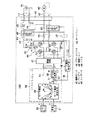
図10は一般的な電動式パワーステアリング回路装置を一部ブロック図で示す回路図である。図10において、40は図示しない車両のハンドルに対して補助トルクを出力する電動モータ、41は電動モータ40を駆動するためのモータ電流IMを供給するバッテリである。また、42はモータ電流IMのリップル成分を吸収するための大容量(2200μF程度)のコンデンサ、43はモータ電流IMを検出するためのシャント抵抗器、44はモータ電流IMを補助トルクの大きさおよび方向に応じて切り換えるための例えばFET(Field Effect Transistor)等の複数の半導体スイッチング素子Q1〜Q4からなるブリッジ回路、49は電磁ノイズを除去するためのコイルである。
【0004】
L1はコンデンサ42の一端をグランドに接続する導電線、P1およびP2は半導体スイッチング素子Q1〜Q4をブリッジ接続するとともにシャント抵抗器43およびブリッジ回路44を接続する配線パターン、P3はブリッジ回路44の出力端子となる配線パターンである。45は電動モータ40およびバッテリ41をブリッジ回路44に接続するための複数のリード端子からなるコネクタ、L2は電動モータ40およびバッテリ41とコネクタ45を接続するための外部配線、46はモータ電流IMを必要に応じて通電遮断するための常開の電源リレー、P4は電源リレー46、コンデンサ42およびシャント抵抗器43を接続する配線パターン、P5はコネクタ45をグランドに接続する配線パターンである。ブリッジ回路44の出力端子となる配線パターンP3はコネクタ45に接続されている。
【0005】
47はブリッジ回路44を介して電動モータ40を駆動するとともに、リレー46を駆動する駆動回路、L3は駆動回路47を電源リレー46の励磁コイルに接続する導電線、L4は駆動回路47をブリッジ回路44に接続する導電線、48はシャント抵抗器43の一端を介してモータ電流IMを検出するモータ電流検出手段であり、駆動回路47およびモータ電流検出手段48は後述するマイクロコンピュータの周辺回路素子を構成している。また、50はハンドルの操舵トルクTを検出するトルクセンサ、51は車両の車速Vを検出する車速センサである。さらに、55はトルクセンサ50および車速センサ51の出力を入力し操舵トルクTおよび車速Vに基づいて補助トルクを演算するとともにモータ電流IMをフィードバックして補助トルクに相当する駆動信号を生成するマイクロコンピュータ(ECU)であり、ブリッジ回路44を制御するための回転方向指令D0および電流制御量I0を駆動信号として駆動回路47に入力する。
【0006】
マイクロコンピュータ55は、電動モータ40の回転方向指令D0および補助トルクに相当するモータ電流指令Imを生成するモータ電流決定手段56と、モータ電流指令Imとモータ電流IMとの電流偏差ΔIを演算する演算手段57と、電流偏差ΔIからP(比例)項、I(積分)項およびD(微分)項の補正量を算出してPWMデューティ比に相当する電流制御量I0を生成するPID演算手段58とを備えている。また、図示していないが、マイクロコンピュータ55は、AD変換器やPWMタイマ回路等の他に周知の自己診断機能を含み、システムが正常に動作しているか否かを常に自己診断しており、異常が発生すると駆動回路47を介して電源リレー46を開放し、モータ電流IMを遮断するようになっている。L5はマイクロコンピュータ55を駆動回路47に接続するための導電線である。
【0007】
一般に、電動モータ40とバッテリ41との間に介在された回路要素42〜44、49、配線パターンP1〜P5、導電線L1およびL2は、大電流のモータ電流IMに対応するため、後述するように放熱性(耐熱性)および耐久性等を考慮して、大型に構成されている。一方、マイクロコンピュータ55、駆動回路47およびモータ電流検出回路48を含む周辺回路素子ならびに導電線L3〜L5は、小電流に対応しており、また高密度が要求されるため、小型に構成されている。
【0008】
図11は一般的な電動式パワーステアリング回路装置の回路構成を示す平面図であり、図中、Q1〜Q4、42、43、45、46、49および55は図10に示すものと同様のものを示している。この例の場合、半導体スイッチング素子Q1〜Q4は樹脂で被覆された各一対のFETにより構成され、大容量コンデンサ42は3個のコンデンサにより構成され、マイクロコンピュータ55は1チップのICにより構成されている。また、図面の煩雑さを防ぐために、周辺回路素子、配線パターンおよび導電線等を省略し、代表的な回路要素のみを示す。図11において、1はシールド板およびヒートシンクの機能を兼ねた箱型の金属フレーム、2は金属フレーム1の底面上に載置された絶縁プリント基板、3は金属フレーム1の内側面に一端面が接合された例えばアルミニウムで作製されたヒートシンクである。絶縁プリント基板2には、各回路要素42、43、46、49および55等が載置されており、また、ヒートシンク3の他端面には各半導体スイッチング素子Q1〜Q4が接合されている。4a〜4eは配線パターンP1〜P5等に相当する配線板であり、大電流に専用に対応するために、絶縁プリント基板2上の配線パターンとは別に幅および厚さの大きい導電板が用いられている。
【0009】
次に、図10を参照しながら、図11に示した従来の電動式パワーステアリング回路装置の動作について説明する。マイクロコンピュータ55は、トルクセンサ50および車速センサ51から操舵トルクTおよび車速Vを取り込むとともに、シャント抵抗器43からモータ電流IMをフィードバック入力し、パワーステアリングの回転方向指令D0と、補助トルクに相当する電流制御量I0とを生成し、導電線L5を介して駆動回路47に入力する。駆動回路47は、定常駆動状態では導電線L3を介した指令により常開の電源リレー46を閉成しており、回転方向指令D0および電流制御量I0が入力されると、PWM駆動信号を生成し、導電線L4を介してブリッジ回路44の半導体スイッチング素子Q1〜Q4に印加する。これにより、電動モータ40は、バッテリ41から外部配線L2、コネクタ45、コイル49、電源リレー46、配線パターンP4、シャント抵抗器43、配線パターンP1、ブリッジ回路44、配線パターンP3、コネクタ45および外部配線L2を介して供給されるモータ電流IMにより駆動され、所要方向に所要量の補助トルクを出力する。
【0010】
このとき、モータ電流IMは、シャント抵抗器43およびモータ電流検出手段48を介して検出され、マイクロコンピュータ55内の演算手段57にフィードバックされることにより、モータ電流指令Imと一致するよう制御される。また、モータ電流IMは、ブリッジ回路44のPWM駆動時のスイッチング動作によりリップル成分を含むが、大容量のコンデンサ42により平滑されて制御される。さらに、コイル49は、上記ブリッジ回路44がPWM駆動時に、スイッチング動作することにより発生するノイズが外部に放出されて、ラジオノイズとなることを防止する。
【0011】
【発明が解決しようとする課題】
この種の電動式パワーステアリング回路装置で制御されるモータ電流IMの値は、軽自動車であっても25A程度であり、小型自動車では45A〜60A程度にも達する。従って、ブリッジ回路44を構成する半導体スイッチング素子Q1〜Q4は、モータ電流IMの大きさに対応して大型化するとともに、図示したように複数個を並列接続して、オン時およびPWMスイッチング時の発熱を抑制する必要がある。また、半導体スイッチング素子Q1〜Q4の発熱量を放熱するために、ヒートシンク3が必要であり、モータ電流IMが大きくなればなるほど半導体スイッチング素子Q1〜Q4の個数も増加し、同時にヒートシンク3も大型化することになる。さらに、コネクタ45の端子から、コイル49、電源リレー46、シャント抵抗器43およびブリッジ回路44を経由したグランドまでの配線パターンP1、P2およびP4、ならびに、ブリッジ回路44から電動モータ40までの配線パターンP3の長さは、モータ電流IMの大電流化、半導体スイッチング素子Q1〜Q4の個数の増加、ならびに、ヒートシンク3の大型化に比例して、物理的に長くなる。
【0012】
この結果、従来の電動式パワーステアリング回路装置では、各配線パターンP1〜P4での電圧降下に起因する発熱量により、温度上昇が大きくなると、配線パターンP1〜P4の耐熱性および耐久性を損なうおそれがあるので、これを防止するために、図11のように幅や厚さの大きい大電流専用の配線板4a〜4eが用いられている。従って、絶縁プリント基板2の大型化を招くことになる。また、コンデンサ42、シャント抵抗器43、電源リレー46およびコイル49は、モータ電流IMの大電流化に伴い大型化するが、これらを絶縁プリント基板2上に搭載しようとすると、搭載スペースの増大により、さらに絶縁プリント基板2の大型化を招くことになる。
【0013】
この発明は上述のような課題を解消するためになされたもので、部品の実装に関し、小電流部品を実装する基板と大電流部品を実装する基板との2つの基板と、大型部品を実装するハウジングに分割して小型化を達成するとともに、ハウジングに配線パターンを形成して2つの基板とハウジングを効率的に電気的接続し、インサート成型前のパワー部の配線パターンを1つの部品で構成することにより、コストダウンや作業性の向上および大出力化を可能にする電動式パワーステアリング回路装置およびその製造方法を得ることを目的とする。
【0014】
【課題を解決するための手段】
この発明に係る電動式パワーステアリング回路装置は、車両のハンドルに連結されハンドルに対して補助トルクを出力する電動モータと、電動モータに駆動電流を供給するバッテリと、ハンドルの操舵トルクを検出するトルクセンサと、車両の車速を検出する車速センサと、ハンドルに対する補助トルクに基づいて電動モータの駆動電流を切り換える複数の半導体スイッチング素子からなるブリッジ回路および駆動電流のリップルを吸収するコンデンサを搭載するパワー基板と、ハンドルの操舵トルクと車両の車速に基づいてブリッジ回路を制御する駆動信号を生成するマイクロコンピュータおよびその周辺回路素子を搭載する制御基板と、ブリッジ回路のスイッチング動作時に発生するノイズの外部流出を防止するコイルと、バッテリからブリッジ回路に供給される駆動電流を開閉する電源リレーと、ブリッジ回路から電動モータに供給される駆動電流を開閉するモータリレーと、電動モータおよびバッテリと電気的に接続されるパワーコネクタと、一端がパワーコネクタに接続され電動モータの駆動電流が流れる配線パターンが形成された導電板と、パワー基板と制御基板とを電気的に接続する接続端子と、絶縁性樹脂でなり、パワーコネクタ、導電板および接続端子がインサート成型されるハウジングと、半導体スイッチング素子の発熱を放熱するヒートシンクとを備えた電動パワーステアリング回路装置において、ハウジングにインサート成型される前の導電板は、配線パターンが連続的に繋がれて形成された一枚の導電性金属板で構成され、配線パターンはインサート成型の後に不要部分が除去されて所定の配線パターンとなるとともに、導電板は、パワー基板とハウジングとを固定する 固定位置の近傍でパワー基板と電気的に接続されており、導電板は、パワー基板とハウジングとを固定する複数の固定位置を結ぶ線の近傍でパワー基板と電気的に接続されており、導電板とパワー基板との電気的接続箇所は、バッテリに接続される導電板とパワー基板とが電気的接続された箇所と、電動モータに接続される導電板とパワー基板とが電気的接続された箇所とに、パワー基板とハウジングとを固定する複数の固定位置を結ぶ線で分割されている。
【0015】
また、導電板とパワー基板の電気的接続箇所は、パワー基板とハウジングとを固定する複数の固定位置を結ぶ線の両側に同じ個数ずつ配設されている。
【0016】
また、接続端子は、少なくとも車速センサと電気的に接続される端子を含む信号用コネクタの近傍に配設されており、信号用コネクタは、ハウジングと一体成型されるとともに、接続端子と信号用コネクタの端子は、制御基板と電気的に接続される箇所が整列して設けられている。
【0017】
また、ハウジングには、コイル、電源リレー、またはモータリレーのうち、少なくとも1つが挿入される凹部が形成され、コンデンサは、ハウジングの信号用コネクタおよび凹部と反対側で、かつパワー基板の角部付近の位置に配設されている。
【0018】
また、制御基板は、パワー基板と概略平行に配置されるとともに、コンデンサと重なる部分が切り欠かれている。
【0019】
また、トルクセンサと電気的に接続されるトルクセンサコネクタは、ハウジングと別体に構成され、ハウジングの凹部側で、かつパワーコネクタの反対側に配置されている。
【0020】
また、トルクセンサコネクタは、少なくとも1部がパワー基板を介してヒートシンクに固定されている。
【0021】
【発明の実施の形態】
以下、この発明の実施の形態を図について説明する。
実施の形態1.
図1はこの発明の実施の形態1に係る電動式パワーステアリング回路装置を示す一部ブロック図である。図1において、40は図示しない車両のハンドルに対して補助トルクを出力する電動モータ、41は電動モータ40を駆動するためのモータ電流IMを供給するバッテリである。また、42はモータ電流IMのリップル成分を吸収するための大容量(2200μF程度)のコンデンサ、43はモータ電流IMを検出するためのシャント抵抗器、44はモータ電流IMを補助トルクの大きさおよび方向に応じて切り換えるための例えばFET等の複数の半導体スイッチング素子Q1〜Q4からなるブリッジ回路、49は電磁ノイズを除去するためのコイルである。
【0022】
P1およびP2は半導体スイッチング素子Q1〜Q4をブリッジ接続するとともにシャント抵抗器43およびブリッジ回路44を接続する配線パターン、P3はブリッジ回路44の出力端子となる配線パターンである。45は電動モータ40およびバッテリ41をブリッジ回路44に接続するための複数のリード端子からなるコネクタ、L2は電動モータ40およびバッテリ41とコネクタ45を接続するための外部配線、46はモータ電流IMを必要に応じて通電遮断するための常開の電源リレー、P4は電源リレー46、コンデンサ42およびシャント抵抗器43を接続する配線パターン、P5はコネクタ45をグランドに接続する配線パターンであり、コンデンサ42の一端をグランドに接続する配線パターンも含む。ブリッジ回路44の出力端子となる配線パターンP3はコネクタ45に接続されている。
【0023】
47はブリッジ回路44を介して電動モータ40を駆動するとともに、電源リレー46およびモータリレー60を駆動する駆動回路、L3は駆動回路47を電源リレー46およびモータリレー60の励磁コイルに接続する導電線、L4は駆動回路47をブリッジ回路44に接続する導電線、48はシャント抵抗器43の一端を介してモータ電流IMを検出するモータ電流検出手段であり、駆動回路47およびモータ電流検出手段48は後述するマイクロコンピュータの周辺回路素子を構成している。また、50はハンドルの操舵トルクTを検出するトルクセンサ、51は車両の車速Vを検出する車速センサである。さらに、55はトルクセンサ50および車速センサ51の出力を入力し操舵トルクTおよび車速Vに基づいて補助トルクを演算するとともにモータ電流IMをフィードバックして補助トルクに相当する駆動信号を生成するマイクロコンピュータ(ECU)であり、ブリッジ回路44を制御するための回転方向指令D0および電流制御量I0を駆動信号として駆動回路47に入力する。
【0024】
マイクロコンピュータ55は、電動モータ40の回転方向指令D0および補助トルクに相当するモータ電流指令Imを生成するモータ電流決定手段56と、モータ電流指令Imとモータ電流IMとの電流偏差ΔIを演算する演算手段57と、電流偏差ΔIからP(比例)項、I(積分)項およびD(微分)項の補正量を算出してPWMデューティ比に相当する電流制御量I0を生成するPID演算手段58とを備えている。また、図示していないが、マイクロコンピュータ55は、AD変換器やPWMタイマ回路等の他に周知の自己診断機能を含み、システムが正常に動作しているか否かを常に自己診断しており、異常が発生すると駆動回路47を介して電源リレー46を開放し、モータ電流IMを遮断するようになっている。L5はマイクロコンピュータ55を駆動回路47に接続するための導電線である。
【0025】
そして、本実施の形態においては、モータ電流を開閉するモータ用リレー60が電動モータ40と駆動回路47との間に配設されている。そして、電動モータ40とバッテリ41との間に介在された回路要素42〜44、46、49、60、配線パターンP1〜P5、導電線L2は、大電流のモータ電流IMに対応するために、放熱性および耐久性等を考慮して、大型に構成されている。一方、マイクロコンピュータ55、駆動回路47およびモータ電流検出回路48を含む周辺回路素子、導電線L3〜L5は、小電流に対応しており、また高密度が要求されるため、小型に構成されている。
【0026】
次に、動作について説明する。マイクロコンピュータ55は、トルクセンサ50および車速センサ51から操舵トルクTおよび車速Vを取り込むとともに、シャント抵抗器43からモータ電流IMをフィードバック入力し、パワーステアリングの回転方向指令D0と、補助トルクに相当する電流制御量I0とを生成し、導電線L5を介して駆動回路47に入力する。駆動回路47は、定常駆動状態では導電線L3を介した指令により常開の電源リレー46およびモータリレー60を閉成しており、回転方向指令D0および電流制御量I0が入力されると、PWM駆動信号を生成し、導電線L4を介してブリッジ回路44の半導体スイッチング素子Q1〜Q4に印加する。これにより、電動モータ40は、バッテリ41から外部配線L2、コネクタ45、コイル49、電源リレー46、配線パターンP4、シャント抵抗器43、配線パターンP1、ブリッジ回路44、配線パターンP3、コネクタ45、モータリレー60および外部配線L2を介して供給されるモータ電流IMにより駆動され、所要方向に所要量の補助トルクを出力する。
【0027】
このとき、モータ電流IMは、シャント抵抗器43およびモータ電流検出手段48を介して検出され、マイクロコンピュータ55内の演算手段57にフィードバックされることにより、モータ電流指令Imと一致するよう制御される。また、モータ電流IMは、ブリッジ回路44のPWM駆動時のスイッチング動作によりリップル成分を含むが、大容量のコンデンサ42により平滑されて制御される。さらに、コイル49は、上記ブリッジ回路44がPWM駆動時に、スイッチング動作することにより発生するノイズが外部に放出されて、ラジオノイズとなることを防止する。
【0028】
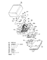
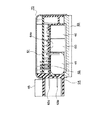
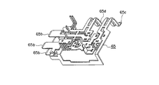
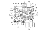
図2はこの発明の実施の形態1に係る電動式パワーステアリング回路装置の分解斜視図、図3はハウジングの部品取り付け状態を示す上面図、図4は図3のIV-IV線に沿う電動式パワーステアリング回路装置の矢視断面図、図5は導電板の展開図、図6は導電板のインサート成型前の状態を示す斜視図である。
【0029】
図1乃至図6において、制御基板61は絶縁プリント基板からなる。そして、マイクロコンピュータ55、駆動回路47およびモータ電流検出回路48(図示せず)を含む周辺回路素子(小電流部品)が、制御基板61上の配線パターン(L5等)に半田付けされて実装されている。
【0030】
パワー基板としての金属基板62は、例えばHITT基板(電気化学工業の商品名)からなり、2mmのアルミニウム板上に80μmの絶縁層を介して、配線パターン(P1、P2等)が70μmの銅パターンとして形成されている。この金属基板62は、裏面をヒートシンク63の一側のほぼ半分わたって密接するようにヒートシンク63上に取り付けられ、放熱機能が増大されている。また、ブリッジ回路44を構成する半導体スイッチング素子Q1〜Q4、コンデンサ42、シャント抵抗器43等の大電流部品が金属基板62上の配線パターン(P1、P2等)に半田付けされて実装されている。この金属基板62上に形成された配線パターンは、大電流に対応できるように十分な断面容量を有し、モータ電流IMが流れる回路要素を実装できるようになっている。
【0031】
ハウジング64は、ヒートシンク63とほぼ一致する外径形状を有し、導電板65、接続端子66、信号用コネクタ67の端子67aが絶縁性樹脂にインサート成型されて作製されるものである。ハウジング64には、図4の下方側に開口を有する凹部64aが形成されている。この凹部64aには、電源リレー46、モータリレー60、コイル49が収納されている。さらに、ハウジング64には、凹部64aの反対側において、図2の上下方向に貫通する空間で図2の上下に開口を有する開口部64bが形成されている。この開口部64b内には、金属基板62が配設される。さらにまた、ハウジング64には、パワーコネクタ45が凹部64a側の側面に突出して形成され、また、信号用コネクタ67がパワーコネクタ45と並んで金属基板62側の側面に突出して形成されている。この信号用コネクタ67は、トルクセンサ50および車速センサ51に接続される端子を含んでいる。
【0032】
また、導電板65は導電性の優れた銅合金の1枚の板よりプレス加工により形成され、各々の回路パターンはインサート成型前に分散しないようタイバー65a(図5のハッチング部分)で部分的に繋がれて形成されている(導電性金属板作製工程)。このように形成された導電板65は、図5に示す18箇所の1点鎖線で折り曲げられて、図6に示すような立体形状とされ、その後、タイバー65aが露出するように絶縁性樹脂にインサート成型される。そして、インサート成型の後、露出されたタイバーが切断されて、電動モータ40とバッテリ41の間に介在される電源リレー46、モータリレー60、コイル49等の回路要素を接続する配線パターンを構成する(不要部分除去工程)。
【0033】
そして、この配線パターンの一部が露出して前記回路要素の端子を接続する電極を形成し、また他の一部がパワーコネクタ45内に延出してパワーコネクタ45内の端子65bを形成する。この配線パターンの露出部の電極の孔に電源リレー46、モータリレー60およびコイル49等の端子が挿入されて半田付けされる。一方、前記パワーコネクタ45内の端子65bは2段、2列で構成され、一方の列はバッテリ41に接続され、他方の列は電動モータ40に接続されるとともに、例えば図4において上側となる端子65bは、電源リレー46、モータリレー60、コイル49と接続される電極部まで同一面で形成されている。さらに、配線パターンの一部が開口部64b内に露出して、配線パターンP4、P5に相当する電源端子65c、配線パターンP3に相当するモータ端子65dを構成している。
【0034】
ハウジング64は、金属基板62の対向する辺の中央付近において、2個のネジ68で金属基板62に締着されている。図3に示されるように、これら2個のネジ68を結ぶ線I−Iの近傍において、電源端子65c、モータ端子65dおよび接続端子66が金属基板62の配線パターンに半田接合されている。また、その配置は、I−I線を挟んで一方の側に2個の電源端子65cが配設され、もう一方の側に2個のモータ端子65dが配設されている。さらに、接続端子66の金属基板62との接合部の反対側は、信号用コネクタ67の端子67aの近傍に配設されており、また、接続端子66の制御基板61を取り付けた際に制御基板61の各スルーホール内に挿入される部分は、2列に整列されて配置されている。
【0035】
図6に良く示されるように、導電板65からは、制御基板61への電源供給用端子、電源リレー46およびモータリレー60の駆動するための信号用端子等が制御基板61側に突出しており、制御基板61を取り付けた際に、制御基板61の各スルーホール内に挿入されて、半田付けされる。そして、コンデンサ42は、制御基板61のスルーホールへ挿入される端子から離れた位置、すなわち信号用コネクタ67およびハウジング凹部64aと反対側の金属基板62の角部に配設されている。さらに、制御基板61と金属基板62とは、ハウジング64を挟んで図2の上下方向で平行に配置されており、制御基板61のコンデンサ42と重なる角部は、コンデンサ42と接触しないように切り欠いて削除されている。
【0036】
金属基板62が固定されたハウジング64は、金属基板62の角部の4箇所と、ハウジング凹部64aの外側1箇所の合計5箇所において、ネジ69でヒートシンク63に締着されている。カバー70は鉄にて作製され、金属基板62、ハウジング64および制御基板61を覆うように被せられて縁部がヒートシンク63に固定される。
【0037】
このように構成された電動式パワーステアリング回路装置を組み立てるには、まず、各電極にクリーム半田を塗布した制御基板61上にマイクロコンピュータ55およびその周辺回路素子等の部品を配置し、リフロ装置を用いて、制御基板61の下側から、または周囲の雰囲気全体を熱し、クリーム半田を溶かして各部品を半田付けする。同様に、各電極にクリーム半田を塗布した金属基板62上に半導体スイッチング素子Q1〜Q4、シャント抵抗器43およびコンデンサ42等の部品を配置し、金属基板62上にハウジング64を被せてネジ68で固定し、リフロ装置を用いてクリーム半田を溶かし、各部品と端子65c、65dおよび接続端子66を半田付けする。このとき、端子65c、65dおよび接続端子66は、弾性変形することにより先端部が金属基板62に押し付けられており、その反力で金属基板62が変形しようとするが、ネジ68を結ぶ線I−Iの近傍に、電源端子65c、モータ端子65dおよび接続端子66が配置されているので、金属基板62の変形が抑制される。また、大電流が流れるため幅が広くなって曲げ剛性の大きい端子65c、65dが、ネジ68を結ぶ線I−Iの両側に2個ずつ配置されているので、金属基板62の変形が両側均等に近づき、金属基板62の変形が抑制される。さらに、ネジ68を結ぶ線I−Iの一方の側に2個の電源端子65cが近接して配設され、もう一方の側に2個のモータ端子65dが近接してグループとして配設されているので、それぞれのグループで電流が往復しており、電磁ノイズの発生が抑制される。そして、電源リレー46、モータリレー60およびコイル49等がハウジング64の凹部64a内に納められ、導電板65の電極から突出する各部品の端子が部分噴流により一括で半田付け接合され、ハウジング64に各部品が実装される。
【0038】
ついで、制御基板61がハウジング64の上部に配置される。そして、ハウジング64側の導電板65の端子、接続端子66および信号用コネクタ67の端子67aが制御基板61のスルーホール内に挿入され、部分噴流により一括で半田付け接合される。このとき、制御基板61のスルーホール内に挿入される接続端子66および信号用コネクタ67の端子67aが混合され、かつ、2列に整列して配置されているので、端子を制御基板61のスルーホールへ挿入することが容易である。さらに、制御基板61のスルーホール内に挿入される端子が、制御基板61の二辺に集中しているので、端子をスルーホールへ挿入することが容易である。また、コンデンサ42は、制御基板61のスルーホールへ挿入される端子から離れた位置、すなわち信号用コネクタ67およびハウジング凹部64aと反対側の金属基板62の角部に配設されており、制御基板61は、コンデンサ42と重なる角部が切り欠いた形状に形成されているので、制御基板61をハウジング64に装着したとき、制御基板61とコンデンサ42の干渉が無く、装置の高さを低くすることができる。ついで、ハウジング64を上方からヒートシンク63上に配置し、ネジ69により固定する。このとき、金属基板62は、四隅のネジ69によりヒートシンク63に固定されるので、金属基板62が密着してヒートシンク63押し付けられる。
【0039】
このように、本実施の形態によれば、マイクロコンピュータ55およびその周辺回路素子等の小電流部品のみが制御基板61に実装されているので、配線パターンの幅や厚さを大きくする必要がなく、部品の高密度実装が可能となり、基板の小型化を図ることができる。また、半導体スイッチング素子Q1〜Q4、シャント抵抗器43およびコンデンサ42等の大電流部品が金属基板62に実装され、この金属基板62がヒートシンク63に密接状態で取り付けられているので、大電流部品および配線パターンからの発熱量が金属基板62を介してヒートシンク63に有効に伝達され、ヒートシンク63から外気に放熱され、金属基板62を小型化しても温度上昇を抑制できるとともに、配線パターンの耐熱性および耐久性を損なうこともない。
【0040】
また、導電板65は導電性の優れた銅合金の1枚の板よりプレス加工により形成され、各々の回路パターンはインサート成型前に分散しないようタイバー65a(図5のハッチング部分)で部分的につながれており、タイバー65aが露出するように絶縁性樹脂にインサート成型され、その後、露出されたタイバーが切断されて、電動モータ40とバッテリ41の間に介在される電源リレー46、モータリレー60、コイル49等の回路要素を接続する配線パターンを構成しているので、材料の歩留まりがよく、低コスト化を図ることができ、導電板65は、ハウジング64の成形型への装填性がよくなり、作業性の向上を図ることができる。
【0041】
また、パワーコネクタ45の端子65bは2段、2列で構成され、図4の上段側は電源リレー46、モータリレー60、コイル49と接続される電極部まで同一面で形成されているので、導電板65の材料の歩留まりがよく、プレス加工において曲げの工程が少なくなるため、コスト低減を図ることができる。
【0042】
また、ハウジング64は、金属基板62の対向する辺の中央付近において、2個のネジ68で金属基板62に取り付けられ、これら2個のネジ68を結ぶ線I−Iの近傍に、電源端子65c、モータ端子65dおよび接続端子66が金属基板62の配線パターンに半田接合されているので、金属基板62の変形が抑制され、リフロ後ヒートシンク63に密接させたとき金属基板62の変形が抑制され、金属基板62の配線パターンの半田接合部に印加される応力が低減され、耐久性が向上する。
【0043】
また、大電流が流れるため幅が広くなって曲げ剛性の大きい端子65c、65dが、ネジ68を結ぶ線I−Iの両側に2個ずつ配置されているので、金属基板62の変形が両側均等に近づき、金属基板62の変形が抑制され、金属基板62の配線パターンの半田接合部に印加される応力が低減され、耐久性が向上する。
【0044】
また、ネジ68を結ぶ線I−Iの一方の側に2個の電源端子65cが近接して配設され、もう一方の側に2個のモータ端子65dが近接してグループとして配設されているので、それぞれのグループで電流が往復して電磁ノイズの発生が抑制され、ラジオノイズの低減を図ることができる。
【0045】
また、接続端子66の金属基板62との接合部の反対側は、信号用コネクタ67の端子67aの近傍に配設され、制御基板61を取り付けた際に、制御基板61の各スルーホール内に挿入される部分は、2列に整列されて配置されるとともにハウジング64に一体的にインサート成型されているので、端子を制御基板61のスルーホールへ挿入することが容易になり作業性が向上する。
【0046】
また、コンデンサ42は、制御基板61のスルーホールへ挿入される端子から離れた位置、すなわち信号用コネクタ67およびハウジング凹部64aと反対側の金属基板62の角部に配設され、制御基板61は、コンデンサ42と重なる角部が切り欠いた形状に形成されているので、制御基板61をハウジング64に装着したとき、制御基板61とコンデンサ42の干渉が無く、高さ方向の小型化を図ることができる。
【0047】
また、金属基板62は、四隅のネジ69によりヒートシンク63に固定されるので、金属基板62が密着してヒートシンク63に押し付けられ、耐熱性および耐久性の向上を図ることができる。なお、金属基板62としてHITT基板を用いているが、金属基板62はHITT基板に限定されるものではなく、配線パターンが絶縁層を介してアルミニウム等の伝熱性のよい金属ベース上に形成されたものであればよい。また、リレーは、電源リレー46またはモータリレー60のいずれか1個を取り付ける場合であってもよい。また、パワーコネクタ45は電源用の2極と、電動モータ用の2極を並べて配置しているが、4極の1個のコネクタで構成してもよい。また、ハウジング64と金属基板62の固定および金属基板62が組み立てられたハウジング64とヒートシンク63の固定はネジ68、69を用いたが、リベット等他の固定手段であってもよい。
【0048】
実施の形態2.
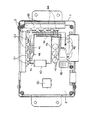
図7はこの発明の実施の形態2に係る電動式パワーステアリング回路装置を示す分解斜視図、図8はこの発明の実施の形態2に係る電動式パワーステアリング回路装置におけるハウジングの部品取り付け状態を示す上面図である。本実施の形態は電動式パワーステアリング回路装置がトルクセンサ50の近傍に装着され、トルクセンサ50と直接結線される場合に有効である。
【0049】
図7、図8において、トルクセンサコネクタ80は、ハウジング64とは別の部品で構成され、トルクセンサ50に接続される端子80aが装着されて、ハウジング64の凹部64a側(図4)でかつ、パワーコネクタ45の反対側に、2個のネジ69でヒートシンク63に固定されている。このとき、トルクセンサコネクタ80は、一方のネジ69で金属基板62を介してヒートシンク63に固定され、もう一方のネジ69で直接ヒートシンク63に固定されている。そして、本実施の形態においては、信号用コネクタ67からトルクセンサ50に接続される端子をトルクセンサコネクタ80に移設しているので、信号用コネクタ67は車速センサ51に接続される端子を含んでいるが、トルクセンサ50に接続される端子は含んでいない。
なお、他の構成は上述の実施の形態1と同様に構成されている。
【0050】
本実施の形態では、マイクロコンピュータ55およびその周辺回路素子等の部品が半田付けされて実装された制御基板61のスルーホールに、トルクセンサコネクタ80の端子80aを挿入し、トルクセンサコネクタ80が装着された制御基板61がハウジング64の上部に配置される。そして、ハウジング64側の導電板65端子、接続端子66および信号用コネクタ67の端子67aが制御基板61のスルーホール内に挿入され、部分噴流によりトルクセンサコネクタ80の端子80aを含めて一括で半田付け接合される。ここで、制御基板61のスルーホール内に挿入される端子が、制御基板61の三辺になるが、その内の一辺のトルクセンサコネクタ80端子80aは予め挿入されているので、制御基板61のスルーホール内に挿入されるハウジング64の端子が、制御基板61の二辺となり、端子をスルーホールへ挿入することが容易である。ついで、ハウジング64を上方からヒートシンク63上に配置し、ネジ69により固定する。このとき、金属基板62は、四隅の内、3箇所はハウジング64を介してネジ69によりヒートシンク63に固定され、残りの1箇所はトルクセンサコネクタ80を介してヒートシンク63に固定されるので、金属基板62が密着してヒートシンク63押し付けられる。また、金属基板62固定用ネジ69の一箇所は、トルクセンサコネクタ80の取り付けネジ69と共用しているのでネジ69の使用数が削減される。
【0051】
このように本実施の形態によれば、トルクセンサコネクタ80は、ハウジング64とは別の部品で構成され、制御基板61のスルーホール内に端子80aが予め挿入されているので、端子を制御基板61のスルーホールへ挿入することが容易になり、作業性の向上を図ることができる。また、ハウジング64の凹部64a側でかつ、パワーコネクタ45の反対側に配置され、一方のネジ69で金属基板62を介してヒートシンク63に固定され、もう一方のネジ69で直接ヒートシンク63に固定されているので、ネジ69の使用数が削減され、コストの低減を図ることができる。
【0052】
【発明の効果】
この発明は、以上のように構成されているので、以下に記載されるような効果を奏する。
【0053】
この発明に係る電動式パワーステアリング回路装置は、車両のハンドルに連結されハンドルに対して補助トルクを出力する電動モータと、電動モータに駆動電流を供給するバッテリと、ハンドルの操舵トルクを検出するトルクセンサと、車両の車速を検出する車速センサと、ハンドルに対する補助トルクに基づいて電動モータの駆動電流を切り換える複数の半導体スイッチング素子からなるブリッジ回路および駆動電流のリップルを吸収するコンデンサを搭載するパワー基板と、ハンドルの操舵トルクと車両の車速に基づいてブリッジ回路を制御する駆動信号を生成するマイクロコンピュータおよびその周辺回路素子を搭載する制御基板と、ブリッジ回路のスイッチング動作時に発生するノイズの外部流出を防止するコイルと、バッテリからブリッジ回路に供給される駆動電流を開閉する電源リレーと、ブリッジ回路から電動モータに供給される駆動電流を開閉するモータリレーと、電動モータおよびバッテリと電気的に接続されるパワーコネクタと、一端がパワーコネクタに接続され電動モータの駆動電流が流れる配線パターンが形成された導電板と、パワー基板と制御基板とを電気的に接続する接続端子と、絶縁性樹脂でなり、パワーコネクタ、導電板および接続端子がインサート成型されるハウジングと、半導体スイッチング素子の発熱を放熱するヒートシンクとを備えた電動パワーステアリング回路装置において、ハウジングにインサート成型される前の導電板は、配線パターンが連続的に繋がれて形成された一枚の導電性金属板で構成され、配線パターンはインサート成型の後に不要部分が除去されて所定の配線パターンとなるので、材料の歩留まりが良くなり低コスト化を図ることができる。また、各々の回路パターンはインサート成型前に分散しないのでハウジングの成形型への装填性がよくなり、組立作業性の向上した電動式パワーステアリング回路装置を得ることができる。
また、導電板は、パワー基板とハウジングとを固定する固定位置の近傍でパワー基板と電気的に接続されているので、パワー基板の変形が抑制され、パワー基板の配線パターンの半田接合部に印加される応力が低減されて耐久性が向上する。
また、導電板は、パワー基板とハウジングとを固定する複数の固定位置を結ぶ線の近傍でパワー基板と電気的に接続されているので、パワー基板の変形がさらに抑制され、耐久性がさらに向上する。
また、導電板とパワー基板との電気的接続箇所は、バッテリに接続される導電板とパワー基板とが電気的接続された箇所と、電動モータに接続される導電板とパワー基板とが電気的接続された箇所とに、パワー基板とハウジングとを固定する複数の固定位置を結ぶ線で分割されているので、分割されたそれぞれの構成要素間で電流が往復して流れて電磁ノイズの発生が抑制され、ラジオノイズが防止される。
【0054】
また、導電板とパワー基板の電気的接続箇所は、パワー基板とハウジングとを固定する複数の固定位置を結ぶ線の両側に同じ個数ずつ配設されているので、パワー基板の変形が両側均等に近づき、パワー基板の配線パターンの半田接合部に印加される応力が低減され、耐久性が向上する。
【0055】
また、接続端子は、少なくとも車速センサと電気的に接続される端子を含む信号用コネクタの近傍に配設されているので、そのため、端子を制御基板のスルーホールへ挿入すること容易になり、作業性の向上を図ることができる。
また、信号用コネクタは、ハウジングと一体成型されるとともに、接続端子と信号用コネクタの端子は、制御基板と電気的に接続される箇所が整列して設けられているので、端子を制御基板のスルーホールへ挿入する作業が容易になり、作業性が向上する。
【0056】
また、ハウジングには、コイル、電源リレー、またはモータリレーのうち、少なくとも1つが挿入される凹部が形成され、コンデンサは、ハウジングの信号用コネクタおよび凹部と反対側で、かつパワー基板の角部付近の位置に配設されているので、制御基板の配線パターンの形成および部品の実装が有効に行え、装置の小型化を図ることができる。
【0057】
また、制御基板は、パワー基板と概略平行に配置されるとともに、コンデンサと重なる部分が切り欠かれているので、制御基板をハウジングに装着したとき、制御基板とコンデンサの干渉が無く、高さ方向の小型化を図ることができる。
【0058】
また、トルクセンサと電気的に接続されるトルクセンサコネクタは、ハウジングと別体に構成され、ハウジングの凹部側で、かつパワーコネクタの反対側に配置されているので、制御基板のスルーホール内にトルクセンサコネクタの端子を予め挿入することができ、制御基板をハウジングに装着することが容易になり、作業性の向上を図ることができる。
【0059】
また、トルクセンサコネクタは、少なくとも1部がパワー基板を介してヒートシンクに固定されているので、耐熱性および耐久性が向上するとともに、ネジの使用数が削減されコストが低減する。
【図面の簡単な説明】
【図1】この発明の実施の形態1に係る電動式パワーステアリング回路装置を示す一部ブロック図である。
【図2】この発明の実施の形態1に係る電動式パワーステアリング回路装置の分解斜視図である。
【図3】この発明の実施の形態1に係る電動式パワーステアリング回路装置におけるハウジングの部品取り付け状態を示す上面図である。
【図4】図3のIV-IV線に沿う電動式パワーステアリング回路装置の矢視断面図である。
【図5】この発明の実施の形態1に係る電動式パワーステアリング回路装置の導電板の展開図である。
【図6】この発明の実施の形態1に係る電動式パワーステアリング回路装置の導電板のインサート成型前の状態を示す斜視図である。
【図7】この発明の実施の形態2に係る電動式パワーステアリング回路装置を示す分解斜視図である。
【図8】この発明の実施の形態2に係る電動式パワーステアリング回路装置におけるハウジングの部品取り付け状態を示す上面図である。
【図9】一般的な電動式パワーステアリングを搭載した車両のシステム構成図である。
【図10】一般的な電動式パワーステアリング回路装置を一部ブロック図で示す回路図である。
【図11】一般的な電動式パワーステアリング回路装置の回路構成を示す平面図である。
【符号の説明】
30 ハンドル、40 電動モータ、41 バッテリ、42 コンデンサ、45 パワーコネクタ、46 電源リレー、49 コイル、50 トルクセンサ、51 車速センサ、55 マイクロコンピュータ、60 モータリレー、61 制御基板、62 金属基板(パワー基板)、63 ヒートシンク、64 ハウジング、64a ハウジングの凹部、65 導電板、66 接続端子、67 信号用コネクタ、67a 信号用コネクタの端子、68,69 ネジ、80 トルクセンサコネクタ。[0001]
TECHNICAL FIELD OF THE INVENTION
The present invention relates to an electric power steering device that assists a steering device of a vehicle by a rotational force of an electric motor, and more particularly to a configuration of a control circuit device and a manufacturing method thereof.
[0002]
[Prior art]
FIG. 9 is a system configuration diagram of a vehicle equipped with a general electric power steering. Generally, in a vehicle equipped with an electric power steering device, as shown in FIG. 9, a
[0003]
FIG. 10 is a circuit diagram partially showing a block diagram of a general electric power steering circuit device. In FIG. 10,
[0004]
L1 is a conductive line connecting one end of the
[0005]
A
[0006]
The
[0007]
Generally, the
[0008]
FIG. 11 is a plan view showing a circuit configuration of a general electric power steering circuit device, in which Q1 to Q4, 42, 43, 45, 46, 49 and 55 are the same as those shown in FIG. Is shown. In the case of this example, the semiconductor switching elements Q1 to Q4 are constituted by a pair of FETs covered with resin, the large-
[0009]
Next, the operation of the conventional electric power steering circuit device shown in FIG. 11 will be described with reference to FIG. The
[0010]
At this time, the motor current IM is detected via the
[0011]
[Problems to be solved by the invention]
The value of the motor current IM controlled by this type of electric power steering circuit device is about 25 A even in a light car, and reaches about 45 A to 60 A in a small car. Accordingly, the semiconductor switching elements Q1 to Q4 constituting the
[0012]
As a result, in the conventional electric power steering circuit device, if the temperature rise becomes large due to the amount of heat generated by the voltage drop in each of the wiring patterns P1 to P4, the heat resistance and durability of the wiring patterns P1 to P4 may be impaired. In order to prevent this, wiring boards 4a to 4e having a large width and a thickness and dedicated to a large current are used as shown in FIG. Therefore, the size of the insulating printed board 2 is increased. In addition, the
[0013]
The present invention has been made in order to solve the above-described problems, and relates to mounting of components, and includes mounting two substrates, a substrate mounting a small current component and a substrate mounting a large current component, and mounting a large component. The housing is divided into housings to achieve miniaturization, and a wiring pattern is formed on the housing to efficiently electrically connect the two substrates and the housing, and the wiring pattern of the power section before insert molding is formed by one component. Accordingly, an object of the present invention is to provide an electric power steering circuit device capable of reducing costs, improving workability, and increasing output, and a method of manufacturing the same.
[0014]
[Means for Solving the Problems]
An electric power steering circuit device according to the present invention includes an electric motor connected to a steering wheel of a vehicle and outputting an auxiliary torque to the steering wheel, a battery supplying a driving current to the electric motor, and a torque detecting a steering torque of the steering wheel. A power board equipped with a sensor, a vehicle speed sensor for detecting a vehicle speed of the vehicle, a bridge circuit including a plurality of semiconductor switching elements for switching a drive current of the electric motor based on an auxiliary torque to a steering wheel, and a capacitor for absorbing a ripple of the drive current. A control board mounted with a microcomputer for generating a drive signal for controlling the bridge circuit based on the steering torque of the steering wheel and the vehicle speed of the vehicle, and a control board on which the peripheral circuit elements are mounted, and the outflow of noise generated during the switching operation of the bridge circuit. Prevent coil and from battery A power relay for opening and closing the drive current supplied to the ridge circuit, a motor relay for opening and closing the drive current supplied from the bridge circuit to the electric motor, a power connector electrically connected to the electric motor and the battery, and one end. A conductive plate formed with a wiring pattern connected to the power connector and through which a drive current of the electric motor flows, a connection terminal for electrically connecting the power board and the control board, and an insulating resin; In an electric power steering circuit device including a housing in which connection terminals are insert-molded, and a heat sink that dissipates heat generated by the semiconductor switching element, a wiring pattern is continuously connected to a conductive plate before the housing is insert-molded. It consists of a single conductive metal plate formed by A predetermined wiring pattern unnecessary portion is removed afterAt the same time, the conductive plate fixes the power board and the housing. The conductive plate is electrically connected to the power board in the vicinity of the fixing position, and the conductive plate is electrically connected to the power board in the vicinity of a line connecting a plurality of fixing positions for fixing the power board and the housing. The electrical connection between the board and the power board is where the conductive board connected to the battery and the power board are electrically connected, and the conductive board connected to the electric motor and the power board are electrically connected. Are divided by a line connecting a plurality of fixing positions for fixing the power board and the housing..
[0015]
Further, the same number of electrically connected portions between the conductive plate and the power board are provided on both sides of a line connecting a plurality of fixing positions for fixing the power board and the housing.
[0016]
The connection terminal is provided at least near a signal connector including a terminal electrically connected to the vehicle speed sensor.In addition, the signal connector is formed integrally with the housing, and the connection terminals and the terminals of the signal connector are provided such that the portions electrically connected to the control board are aligned.
[0017]
The housing has a recess into which at least one of a coil, a power relay, and a motor relay is inserted, and the capacitor is located on a side of the housing opposite to the signal connector and the recess and near a corner of the power board. It is arranged at the position.
[0018]
Further, the control board is arranged substantially parallel to the power board, and a portion overlapping the capacitor is cut away.
[0019]
The torque sensor connector electrically connected to the torque sensor is formed separately from the housing, and is arranged on the concave side of the housing and on the opposite side of the power connector.
[0020]
Further, at least a part of the torque sensor connector is fixed to the heat sink via the power board.
[0021]
BEST MODE FOR CARRYING OUT THE INVENTION
Hereinafter, an embodiment of the present invention will be described with reference to the drawings.
Embodiment 1 FIG.
FIG. 1 is a partial block diagram showing an electric power steering circuit device according to Embodiment 1 of the present invention. In FIG. 1,
[0022]
P1 and P2 are wiring patterns connecting the semiconductor switching elements Q1 to Q4 in a bridge and connecting the
[0023]
A
[0024]
The
[0025]
In the present embodiment, a
[0026]
Next, the operation will be described. The
[0027]
At this time, the motor current IM is detected via the
[0028]
FIG. 2 is an exploded perspective view of the electric power steering circuit device according to the first embodiment of the present invention, FIG. 3 is a top view showing a state where components of the housing are mounted, and FIG. 4 is an electric power steering device taken along line IV-IV in FIG. FIG. 5 is a developed view of the conductive plate, and FIG. 6 is a perspective view showing a state before the insert molding of the conductive plate.
[0029]
1 to 6, the
[0030]
The
[0031]
The
[0032]
Further, the
[0033]
Then, a part of the wiring pattern is exposed to form an electrode for connecting a terminal of the circuit element, and another part extends into the
[0034]
The
[0035]
6, terminals for supplying power to the
[0036]
The
[0037]
In order to assemble the electric power steering circuit device configured as described above, first, components such as the
[0038]
Next, the
[0039]
As described above, according to the present embodiment, since only the small current components such as the
[0040]
Further, the
[0041]
Also, the
[0042]
Further, the
[0043]
Further, since two
[0044]
Also, two
[0045]
The opposite side of the
[0046]
The
[0047]
In addition, since the
[0048]
Embodiment 2 FIG.
FIG. 7 is an exploded perspective view showing an electric power steering circuit device according to Embodiment 2 of the present invention, and FIG. 8 shows a state where components of a housing are mounted in the electric power steering circuit device according to Embodiment 2 of the present invention. It is a top view. This embodiment is effective when the electric power steering circuit device is mounted near the
[0049]
7 and 8, the
The other configuration is the same as that of the first embodiment.
[0050]
In this embodiment, the terminal 80a of the
[0051]
As described above, according to the present embodiment, since the
[0052]
【The invention's effect】
The present invention is configured as described above, and has the following effects.
[0053]
An electric power steering circuit device according to the present invention includes an electric motor connected to a steering wheel of a vehicle and outputting an auxiliary torque to the steering wheel, a battery supplying a driving current to the electric motor, and a torque detecting a steering torque of the steering wheel. A power board equipped with a sensor, a vehicle speed sensor for detecting a vehicle speed of the vehicle, a bridge circuit including a plurality of semiconductor switching elements for switching a drive current of the electric motor based on an auxiliary torque to a steering wheel, and a capacitor for absorbing a ripple of the drive current. A control board mounted with a microcomputer for generating a drive signal for controlling the bridge circuit based on the steering torque of the steering wheel and the vehicle speed of the vehicle, and a control board on which the peripheral circuit elements are mounted; Prevent coil and from battery A power relay for opening and closing the drive current supplied to the ridge circuit, a motor relay for opening and closing the drive current supplied from the bridge circuit to the electric motor, a power connector electrically connected to the electric motor and the battery, and one end. A conductive plate formed with a wiring pattern connected to the power connector and through which a drive current of the electric motor flows, a connection terminal for electrically connecting the power board and the control board, and an insulating resin; In an electric power steering circuit device including a housing in which connection terminals are insert-molded and a heat sink that dissipates heat generated by a semiconductor switching element, a wiring pattern is continuously connected to a conductive plate before the housing is insert-molded. It consists of a single conductive metal plate formed by Since a predetermined wiring pattern unnecessary portion is removed after, it is possible to well becomes cost yield of the material. In addition, since the respective circuit patterns are not dispersed before the insert molding, the loadability of the housing into the mold is improved, and an electric power steering circuit device with improved assembling workability can be obtained.
Further, since the conductive plate is electrically connected to the power board in the vicinity of the fixing position for fixing the power board and the housing, deformation of the power board is suppressed, and the conductive board is applied to the solder joint of the wiring pattern of the power board. The applied stress is reduced, and the durability is improved.
In addition, since the conductive plate is electrically connected to the power board near a line connecting a plurality of fixing positions for fixing the power board and the housing, deformation of the power board is further suppressed, and durability is further improved. I do.
In addition, the electrical connection between the conductive plate and the power board includes a portion where the conductive plate connected to the battery and the power board are electrically connected, and a portion where the conductive plate and the power board connected to the electric motor are electrically connected. Since the connection point is divided by a line connecting a plurality of fixing positions for fixing the power board and the housing, current flows back and forth between each of the divided components, and electromagnetic noise is generated. It is suppressed and radio noise is prevented.
[0054]
The same number of electrical connection points between the conductive plate and the power board are provided on both sides of a line connecting a plurality of fixing positions for fixing the power board and the housing. When approaching, the stress applied to the solder joint of the wiring pattern of the power board is reduced, and the durability is improved.
[0055]
In addition, since the connection terminal is provided at least near the signal connector including the terminal electrically connected to the vehicle speed sensor, it is easy to insert the terminal into the through hole of the control board, and the work is facilitated. Performance can be improved.
In addition, the signal connector is integrally molded with the housing, and the connection terminals and the terminals of the signal connector are provided in a position where they are electrically connected to the control board. The work of inserting into the through hole becomes easy, and the workability is improved.
[0056]
The housing has a recess into which at least one of a coil, a power relay, and a motor relay is inserted, and the capacitor is located on a side of the housing opposite to the signal connector and the recess and near a corner of the power board. , The formation of the wiring pattern on the control board and the mounting of the components can be performed effectively, and the size of the device can be reduced.
[0057]
In addition, the control board is arranged substantially parallel to the power board, and the portion overlapping the capacitor is cut off. Therefore, when the control board is mounted on the housing, there is no interference between the control board and the capacitor and the height direction Can be reduced in size.
[0058]
Further, the torque sensor connector electrically connected to the torque sensor is formed separately from the housing, and is arranged on the concave side of the housing and on the opposite side of the power connector, so that the torque sensor connector is provided in the through hole of the control board. The terminals of the torque sensor connector can be inserted in advance, so that the control board can be easily mounted on the housing, and the workability can be improved.
[0059]
Further, since at least a portion of the torque sensor connector is fixed to the heat sink via the power board, heat resistance and durability are improved, and the number of screws used is reduced, thereby reducing costs.
[Brief description of the drawings]
FIG. 1 is a partial block diagram showing an electric power steering circuit device according to Embodiment 1 of the present invention.
FIG. 2 is an exploded perspective view of the electric power steering circuit device according to Embodiment 1 of the present invention.
FIG. 3 is a top view showing a mounted state of parts of a housing in the electric power steering circuit device according to Embodiment 1 of the present invention.
4 is a cross-sectional view of the electric power steering circuit device taken along line IV-IV in FIG.
FIG. 5 is a development view of a conductive plate of the electric power steering circuit device according to Embodiment 1 of the present invention.
FIG. 6 is a perspective view showing a state before the insert molding of the conductive plate of the electric power steering circuit device according to Embodiment 1 of the present invention;
FIG. 7 is an exploded perspective view showing an electric power steering circuit device according to Embodiment 2 of the present invention.
FIG. 8 is a top view showing a mounted state of parts of a housing in an electric power steering circuit device according to Embodiment 2 of the present invention.
FIG. 9 is a system configuration diagram of a vehicle equipped with a general electric power steering.
FIG. 10 is a circuit diagram partially showing a block diagram of a general electric power steering circuit device.
FIG. 11 is a plan view showing a circuit configuration of a general electric power steering circuit device.
[Explanation of symbols]
30 Handle, 40 electric motor, 41 battery, 42 capacitor, 45 power connector, 46 power relay, 49 coil, 50 torque sensor, 51 vehicle speed sensor, 55 microcomputer, 60 motor relay, 61 control board, 62 metal board (power board) ), 63 heat sink, 64 housing, 64a recess of housing, 65 conductive plate, 66 connection terminal, 67 signal connector, 67a signal connector terminal, 68, 69 screw, 80 torque sensor connector.
Claims (7)
上記電動モータに駆動電流を供給するバッテリと、
上記ハンドルの操舵トルクを検出するトルクセンサと、
上記車両の車速を検出する車速センサと、
上記ハンドルに対する上記補助トルクに基づいて上記電動モータの上記駆動電流を切り換える複数の半導体スイッチング素子からなるブリッジ回路および該駆動電流のリップルを吸収するコンデンサを搭載するパワー基板と、
上記ハンドルの操舵トルクと上記車両の車速に基づいて上記ブリッジ回路を制御する駆動信号を生成するマイクロコンピュータおよびその周辺回路素子を搭載する制御基板と、
上記ブリッジ回路のスイッチング動作時に発生するノイズの外部流出を防止するコイルと、
上記バッテリから上記ブリッジ回路に供給される上記駆動電流を開閉する電源リレーと、
上記ブリッジ回路から上記電動モータに供給される上記駆動電流を開閉するモータリレーと、
上記電動モータおよび上記バッテリと電気的に接続されるパワーコネクタと、
一端が上記パワーコネクタに接続され上記電動モータの上記駆動電流が流れる配線パターンが形成された導電板と、
上記パワー基板と上記制御基板とを電気的に接続する接続端子と、
絶縁性樹脂でなり、上記パワーコネクタ、上記導電板および上記接続端子がインサート成型されるハウジングと、
上記半導体スイッチング素子の発熱を放熱するヒートシンクと
を備えた電動パワーステアリング回路装置において、
上記ハウジングにインサート成型される前の上記導電板は、配線パターンが連続的に繋がれて形成された一枚の導電性金属板で構成され、該配線パターンは該インサート成型の後に不要部分が除去されて所定の配線パターンとなるとともに、
上記導電板は、上記パワー基板と上記ハウジングとを固定する固定位置の近傍で上記パワー基板と電気的に接続されており、
上記導電板は、上記パワー基板と上記ハウジングとを固定する複数の固定位置を結ぶ線の近傍で上記パワー基板と電気的に接続されており、
上記導電板と上記パワー基板との電気的接続箇所は、上記バッテリに接続される導電板と上記パワー基板とが電気的接続された箇所と、上記電動モータに接続される導電板と上記パワー基板とが電気的接続された箇所とに、上記パワー基板と上記ハウジングとを固定する複数の固定位置を結ぶ線で分割されている
ことを特徴とする電動式パワーステアリング回路装置。An electric motor coupled to a steering wheel of the vehicle and outputting an assist torque to the steering wheel;
A battery for supplying a drive current to the electric motor;
A torque sensor for detecting a steering torque of the steering wheel,
A vehicle speed sensor for detecting a vehicle speed of the vehicle,
A power board mounted with a bridge circuit including a plurality of semiconductor switching elements for switching the drive current of the electric motor based on the auxiliary torque for the handle and a capacitor for absorbing a ripple of the drive current;
A control board mounted with a microcomputer and a peripheral circuit element for generating a drive signal for controlling the bridge circuit based on the steering torque of the steering wheel and the vehicle speed of the vehicle;
A coil for preventing the outflow of noise generated during the switching operation of the bridge circuit,
A power relay for opening and closing the drive current supplied to the bridge circuit from the battery;
A motor relay that opens and closes the drive current supplied to the electric motor from the bridge circuit;
A power connector electrically connected to the electric motor and the battery;
A conductive plate having one end connected to the power connector and a wiring pattern in which the drive current of the electric motor flows,
A connection terminal for electrically connecting the power board and the control board,
A housing made of an insulating resin, wherein the power connector, the conductive plate and the connection terminal are insert-molded,
An electric power steering circuit device comprising: a heat sink that radiates heat generated by the semiconductor switching element.
The conductive plate before being insert-molded in the housing is formed of a single conductive metal plate formed by continuously connecting wiring patterns, and the wiring pattern is formed by removing unnecessary portions after the insert molding. And become a predetermined wiring pattern ,
The conductive plate is electrically connected to the power board near a fixing position for fixing the power board and the housing,
The conductive plate is electrically connected to the power board in the vicinity of a line connecting a plurality of fixing positions for fixing the power board and the housing,
The electrically connected portion between the conductive plate and the power board includes a portion where the conductive plate connected to the battery and the power board are electrically connected, a conductive plate connected to the electric motor and the power board. The electric power steering circuit device is divided into a line connecting a plurality of fixing positions for fixing the power board and the housing to a portion where the power board and the housing are electrically connected .
ことを特徴とする請求項1に記載の電動式パワーステアリング回路装置。 The electric power steering circuit device according to claim 1, wherein:
上記電動モータに駆動電流を供給するバッテリと、 A battery for supplying a drive current to the electric motor;
上記ハンドルの操舵トルクを検出するトルクセンサと、 A torque sensor for detecting a steering torque of the steering wheel,
上記車両の車速を検出する車速センサと、 A vehicle speed sensor for detecting a vehicle speed of the vehicle,
上記ハンドルに対する上記補助トルクに基づいて上記電動モータの上記駆動電流を切り換える複数の半導体スイッチング素子からなるブリッジ回路および該駆動電流のリップル A bridge circuit comprising a plurality of semiconductor switching elements for switching the drive current of the electric motor based on the auxiliary torque to the handle, and a ripple of the drive current を吸収するコンデンサを搭載するパワー基板と、Power board with a capacitor that absorbs
上記ハンドルの操舵トルクと上記車両の車速に基づいて上記ブリッジ回路を制御する駆動信号を生成するマイクロコンピュータおよびその周辺回路素子を搭載する制御基板と、 A control board mounted with a microcomputer and a peripheral circuit element for generating a drive signal for controlling the bridge circuit based on the steering torque of the steering wheel and the vehicle speed of the vehicle;
上記ブリッジ回路のスイッチング動作時に発生するノイズの外部流出を防止するコイルと、 A coil for preventing the outflow of noise generated during the switching operation of the bridge circuit,
上記バッテリから上記ブリッジ回路に供給される上記駆動電流を開閉する電源リレーと、 A power relay for opening and closing the drive current supplied to the bridge circuit from the battery;
上記ブリッジ回路から上記電動モータに供給される上記駆動電流を開閉するモータリレーと、 A motor relay that opens and closes the drive current supplied to the electric motor from the bridge circuit;
上記電動モータおよび上記バッテリと電気的に接続されるパワーコネクタと、 A power connector electrically connected to the electric motor and the battery;
一端が上記パワーコネクタに接続され上記電動モータの上記駆動電流が流れる配線パターンが形成された導電板と、 A conductive plate having one end connected to the power connector and a wiring pattern in which the drive current of the electric motor flows,
上記パワー基板と上記制御基板とを電気的に接続する接続端子と、 A connection terminal for electrically connecting the power board and the control board,
絶縁性樹脂でなり、上記パワーコネクタ、上記導電板および上記接続端子がインサート成型されるハウジングと、 A housing made of an insulating resin, wherein the power connector, the conductive plate and the connection terminal are insert-molded,
上記半導体スイッチング素子の発熱を放熱するヒートシンクと A heat sink for dissipating heat generated by the semiconductor switching element;
を備えた電動パワーステアリング回路装置において、 In the electric power steering circuit device having
上記ハウジングにインサート成型される前の上記導電板は、配線パターンが連続的に繋がれて形成された一枚の導電性金属板で構成され、該配線パターンは該インサート成型の後に不要部分が除去されて所定の配線パターンとなるとともに、 The conductive plate before being insert-molded in the housing is formed of a single conductive metal plate formed by continuously connecting wiring patterns, and the wiring pattern is formed by removing unnecessary portions after the insert molding. And become a predetermined wiring pattern,
上記接続端子は、少なくとも上記車速センサと電気的に接続される端子を含む信号用コネクタの近傍に配設されており、 The connection terminal is disposed near a signal connector including at least a terminal electrically connected to the vehicle speed sensor,
上記信号用コネクタは、上記ハウジングと一体成型されるとともに、上記接続端子と上記信号用コネクタの端子は、上記制御基板と電気的に接続される箇所が整列して設けられている The signal connector is integrally formed with the housing, and the connection terminals and the terminals of the signal connector are provided such that the portions electrically connected to the control board are aligned.
ことを特徴とする電動式パワーステアリング回路装置。 An electric power steering circuit device, characterized in that:
ことを特徴とする請求項3に記載の電動式パワーステアリング回路装置。 The electric power steering circuit device according to claim 3, wherein:
上記電動モータに駆動電流を供給するバッテリと、 A battery for supplying a drive current to the electric motor;
上記ハンドルの操舵トルクを検出するトルクセンサと、 A torque sensor for detecting a steering torque of the steering wheel,
上記車両の車速を検出する車速センサと、 A vehicle speed sensor for detecting a vehicle speed of the vehicle,
上記ハンドルに対する上記補助トルクに基づいて上記電動モータの上記駆動電流を切り換える複数の半導体スイッチング素子からなるブリッジ回路および該駆動電流のリップルを吸収するコンデンサを搭載するパワー基板と、 A power board mounted with a bridge circuit including a plurality of semiconductor switching elements for switching the drive current of the electric motor based on the auxiliary torque for the handle and a capacitor for absorbing a ripple of the drive current;
上記ハンドルの操舵トルクと上記車両の車速に基づいて上記ブリッジ回路を制御する駆動信号を生成するマイクロコンピュータおよびその周辺回路素子を搭載する制御基板と、 A control board mounted with a microcomputer and a peripheral circuit element for generating a drive signal for controlling the bridge circuit based on the steering torque of the steering wheel and the vehicle speed of the vehicle;
上記ブリッジ回路のスイッチング動作時に発生するノイズの外部流出を防止するコイルと、 A coil for preventing the outflow of noise generated during the switching operation of the bridge circuit,
上記バッテリから上記ブリッジ回路に供給される上記駆動電流を開閉する電源リレーと、 A power relay for opening and closing the drive current supplied to the bridge circuit from the battery;
上記ブリッジ回路から上記電動モータに供給される上記駆動電流を開閉するモータリレーと、 A motor relay that opens and closes the drive current supplied to the electric motor from the bridge circuit;
上記電動モータおよび上記バッテリと電気的に接続されるパワーコネクタと、 A power connector electrically connected to the electric motor and the battery;
一端が上記パワーコネクタに接続され上記電動モータの上記駆動電流が流れる配線パターンが形成された導電板と、 A conductive plate having one end connected to the power connector and a wiring pattern in which the drive current of the electric motor flows,
上記パワー基板と上記制御基板とを電気的に接続する接続端子と、 A connection terminal for electrically connecting the power board and the control board,
絶縁性樹脂でなり、上記パワーコネクタ、上記導電板および上記接続端子がインサート成型されるハウジングと、 A housing made of an insulating resin, wherein the power connector, the conductive plate and the connection terminal are insert-molded,
上記半導体スイッチング素子の発熱を放熱するヒートシンクと A heat sink for dissipating heat generated by the semiconductor switching element;
を備えた電動パワーステアリング回路装置において、 In the electric power steering circuit device having
上記ハウジングにインサート成型される前の上記導電板は、配線パターンが連続的に繋がれて形成された一枚の導電性金属板で構成され、該配線パターンは該インサート成型の後に不要部分が除去されて所定の配線パターンとなるとともに、 The conductive plate before being insert-molded in the housing is formed of a single conductive metal plate formed by continuously connecting wiring patterns, and the wiring pattern is formed by removing unnecessary portions after the insert molding. And become a predetermined wiring pattern,
上記制御基板は、上記パワー基板と概略平行に配置されるとともに、上記コンデンサと重なる部分が切り欠かれている The control board is arranged substantially parallel to the power board, and a portion overlapping the capacitor is cut away.
ことを特徴とする電動式パワーステアリング回路装置。 An electric power steering circuit device, characterized in that:
上記電動モータに駆動電流を供給するバッテリと、 A battery for supplying a drive current to the electric motor;
上記ハンドルの操舵トルクを検出するトルクセンサと、 A torque sensor for detecting a steering torque of the steering wheel,
上記車両の車速を検出する車速センサと、 A vehicle speed sensor for detecting a vehicle speed of the vehicle,
上記ハンドルに対する上記補助トルクに基づいて上記電動モータの上記駆動電流を切り換える複数の半導体スイッチング素子からなるブリッジ回路および該駆動電流のリップルを吸収するコンデンサを搭載するパワー基板と、 A power board mounted with a bridge circuit including a plurality of semiconductor switching elements for switching the drive current of the electric motor based on the auxiliary torque for the handle and a capacitor for absorbing a ripple of the drive current;
上記ハンドルの操舵トルクと上記車両の車速に基づいて上記ブリッジ回路を制御する駆動信号を生成するマイクロコンピュータおよびその周辺回路素子を搭載する制御基板と、 A control board mounted with a microcomputer and a peripheral circuit element for generating a drive signal for controlling the bridge circuit based on the steering torque of the steering wheel and the vehicle speed of the vehicle;
上記ブリッジ回路のスイッチング動作時に発生するノイズの外部流出を防止するコイルと、 A coil for preventing the outflow of noise generated during the switching operation of the bridge circuit,
上記バッテリから上記ブリッジ回路に供給される上記駆動電流を開閉する電源リレーと、 A power relay for opening and closing the drive current supplied to the bridge circuit from the battery;
上記ブリッジ回路から上記電動モータに供給される上記駆動電流を開閉するモータリレーと、 A motor relay that opens and closes the drive current supplied to the electric motor from the bridge circuit;
上記電動モータおよび上記バッテリと電気的に接続されるパワーコネクタと、 A power connector electrically connected to the electric motor and the battery;
一端が上記パワーコネクタに接続され上記電動モータの上記駆動電流が流れる配線パターンが形成された導電板と、 A conductive plate having one end connected to the power connector and a wiring pattern in which the drive current of the electric motor flows,
上記パワー基板と上記制御基板とを電気的に接続する接続端子と、 A connection terminal for electrically connecting the power board and the control board,
絶縁性樹脂でなり、上記パワーコネクタ、上記導電板および上記接続端子がインサート成型されるハウジングと、 A housing made of an insulating resin, wherein the power connector, the conductive plate and the connection terminal are insert-molded,
上記半導体スイッチング素子の発熱を放熱するヒートシンクと A heat sink for dissipating heat generated by the semiconductor switching element;
を備えた電動パワーステアリング回路装置において、 In the electric power steering circuit device having
上記ハウジングにインサート成型される前の上記導電板は、配線パターンが連続的に繋がれて形成された一枚の導電性金属板で構成され、該配線パターンは該インサート成型の後に不要部分が除去されて所定の配線パターンとなるとともに、 The conductive plate before being insert-molded in the housing is formed of a single conductive metal plate formed by continuously connecting wiring patterns, and the wiring pattern is formed by removing unnecessary portions after the insert molding. And become a predetermined wiring pattern,
上記トルクセンサと電気的に接続されるトルクセンサコネクタは、上記ハウジングと別体に構成され、上記ハウジングの凹部側で、かつ上記パワーコネクタの反対側に配置されている A torque sensor connector electrically connected to the torque sensor is formed separately from the housing, and is arranged on the concave side of the housing and on the opposite side of the power connector.
ことを特徴とする電動式パワーステアリング回路装置。 An electric power steering circuit device, characterized in that:
ことを特徴とする請求項6に記載の電動式パワーステアリング回路装置。 The electric power steering circuit device according to claim 6, wherein:
Priority Applications (1)
| Application Number | Priority Date | Filing Date | Title |
|---|---|---|---|
| JP2001217889A JP3600560B2 (en) | 2001-07-18 | 2001-07-18 | Electric power steering circuit device |
Applications Claiming Priority (1)
| Application Number | Priority Date | Filing Date | Title |
|---|---|---|---|
| JP2001217889A JP3600560B2 (en) | 2001-07-18 | 2001-07-18 | Electric power steering circuit device |
Related Child Applications (1)
| Application Number | Title | Priority Date | Filing Date |
|---|---|---|---|
| JP2004243525A Division JP2004345643A (en) | 2004-08-24 | 2004-08-24 | Electric power steering circuit device |
Publications (2)
| Publication Number | Publication Date |
|---|---|
| JP2003026010A JP2003026010A (en) | 2003-01-29 |
| JP3600560B2 true JP3600560B2 (en) | 2004-12-15 |
Family
ID=19052147
Family Applications (1)
| Application Number | Title | Priority Date | Filing Date |
|---|---|---|---|
| JP2001217889A Expired - Lifetime JP3600560B2 (en) | 2001-07-18 | 2001-07-18 | Electric power steering circuit device |
Country Status (1)
| Country | Link |
|---|---|
| JP (1) | JP3600560B2 (en) |
Families Citing this family (6)
| Publication number | Priority date | Publication date | Assignee | Title |
|---|---|---|---|---|
| JP4705415B2 (en) * | 2005-06-17 | 2011-06-22 | 株式会社ミツバ | Electric motor |
| JP5368051B2 (en) * | 2008-10-07 | 2013-12-18 | 光洋電子工業株式会社 | Power steering device bus bar heat dissipation structure |
| JP2010288328A (en) * | 2009-06-09 | 2010-12-24 | Mitsubishi Electric Corp | Electronic controller |
| JP5846941B2 (en) * | 2012-01-31 | 2016-01-20 | ダイヤモンド電機株式会社 | Bracket structure in electric power steering control unit |
| JP5523500B2 (en) * | 2012-04-27 | 2014-06-18 | 三菱電機株式会社 | Electronic control unit |
| JP7282612B2 (en) * | 2019-06-21 | 2023-05-29 | 株式会社ミツバ | Control device and motor device |
-
2001
- 2001-07-18 JP JP2001217889A patent/JP3600560B2/en not_active Expired - Lifetime
Also Published As
| Publication number | Publication date |
|---|---|
| JP2003026010A (en) | 2003-01-29 |
Similar Documents
| Publication | Publication Date | Title |
|---|---|---|
| JP3644835B2 (en) | Electric power steering circuit device | |
| KR0171461B1 (en) | Electric power steering circuit device | |
| JP3638269B2 (en) | Electric power steering device | |
| KR0119573B1 (en) | Circuit apparatus for power steering system | |
| JP4580999B2 (en) | Motor control unit | |
| US7751193B2 (en) | Electronic control apparatus | |
| US7081691B2 (en) | Switching device for controlling large amount of current | |
| JP4410241B2 (en) | Electronic control unit | |
| KR101834092B1 (en) | Lead frame, electronic control device using lead frame, and lead-frame mounting method | |
| JPH11115775A (en) | Motor-driven power steering control device | |
| JP3556121B2 (en) | Electric power steering circuit device | |
| JP3600560B2 (en) | Electric power steering circuit device | |
| JP2000043740A (en) | Electric power steering circuit device | |
| JP3716231B2 (en) | Electric power steering circuit device and manufacturing method thereof | |
| JP3808267B2 (en) | Electric power steering control device | |
| JP3951210B2 (en) | control unit | |
| JP2004345643A (en) | Electric power steering circuit device | |
| JP2008294338A (en) | Power module, and transport machine equipped with the same | |
| JP4203035B2 (en) | Electric power steering control device | |
| JP5804869B2 (en) | Control unit for electric power steering system | |
| CN109661753B (en) | Connection terminal assembly and circuit board using the same | |
| JP2004237832A (en) | Control unit | |
| WO2023007546A1 (en) | Electronic device and electric power steering device | |
| JP2003078107A (en) | Integral power module with built-in connector | |
| JP4038099B2 (en) | Electronic component mounting structure of large current control unit |
Legal Events
| Date | Code | Title | Description |
|---|---|---|---|
| A131 | Notification of reasons for refusal |
Free format text: JAPANESE INTERMEDIATE CODE: A131 Effective date: 20040706 |
|
| A521 | Written amendment |
Free format text: JAPANESE INTERMEDIATE CODE: A523 Effective date: 20040824 |
|
| TRDD | Decision of grant or rejection written | ||
| A01 | Written decision to grant a patent or to grant a registration (utility model) |
Free format text: JAPANESE INTERMEDIATE CODE: A01 Effective date: 20040914 |
|
| A61 | First payment of annual fees (during grant procedure) |
Free format text: JAPANESE INTERMEDIATE CODE: A61 Effective date: 20040916 |
|
| R150 | Certificate of patent or registration of utility model |
Ref document number: 3600560 Country of ref document: JP Free format text: JAPANESE INTERMEDIATE CODE: R150 Free format text: JAPANESE INTERMEDIATE CODE: R150 |
|
| FPAY | Renewal fee payment (event date is renewal date of database) |
Free format text: PAYMENT UNTIL: 20080924 Year of fee payment: 4 |
|
| FPAY | Renewal fee payment (event date is renewal date of database) |
Free format text: PAYMENT UNTIL: 20080924 Year of fee payment: 4 |
|
| FPAY | Renewal fee payment (event date is renewal date of database) |
Free format text: PAYMENT UNTIL: 20090924 Year of fee payment: 5 |
|
| FPAY | Renewal fee payment (event date is renewal date of database) |
Free format text: PAYMENT UNTIL: 20090924 Year of fee payment: 5 |
|
| FPAY | Renewal fee payment (event date is renewal date of database) |
Free format text: PAYMENT UNTIL: 20100924 Year of fee payment: 6 |
|
| FPAY | Renewal fee payment (event date is renewal date of database) |
Free format text: PAYMENT UNTIL: 20110924 Year of fee payment: 7 |
|
| FPAY | Renewal fee payment (event date is renewal date of database) |
Free format text: PAYMENT UNTIL: 20110924 Year of fee payment: 7 |
|
| FPAY | Renewal fee payment (event date is renewal date of database) |
Free format text: PAYMENT UNTIL: 20120924 Year of fee payment: 8 |
|
| FPAY | Renewal fee payment (event date is renewal date of database) |
Free format text: PAYMENT UNTIL: 20130924 Year of fee payment: 9 |
|
| R250 | Receipt of annual fees |
Free format text: JAPANESE INTERMEDIATE CODE: R250 |
|
| R250 | Receipt of annual fees |
Free format text: JAPANESE INTERMEDIATE CODE: R250 |
|
| R250 | Receipt of annual fees |
Free format text: JAPANESE INTERMEDIATE CODE: R250 |
|
| R250 | Receipt of annual fees |
Free format text: JAPANESE INTERMEDIATE CODE: R250 |
|
| R250 | Receipt of annual fees |
Free format text: JAPANESE INTERMEDIATE CODE: R250 |
|
| R250 | Receipt of annual fees |
Free format text: JAPANESE INTERMEDIATE CODE: R250 |
|
| EXPY | Cancellation because of completion of term |