JP3587599B2 - Heat transfer tube for absorber - Google Patents
Heat transfer tube for absorber Download PDFInfo
- Publication number
- JP3587599B2 JP3587599B2 JP26547895A JP26547895A JP3587599B2 JP 3587599 B2 JP3587599 B2 JP 3587599B2 JP 26547895 A JP26547895 A JP 26547895A JP 26547895 A JP26547895 A JP 26547895A JP 3587599 B2 JP3587599 B2 JP 3587599B2
- Authority
- JP
- Japan
- Prior art keywords
- heat transfer
- tube
- transfer tube
- valley
- valleys
- Prior art date
- Legal status (The legal status is an assumption and is not a legal conclusion. Google has not performed a legal analysis and makes no representation as to the accuracy of the status listed.)
- Expired - Fee Related
Links
Images


Classifications
-
- Y—GENERAL TAGGING OF NEW TECHNOLOGICAL DEVELOPMENTS; GENERAL TAGGING OF CROSS-SECTIONAL TECHNOLOGIES SPANNING OVER SEVERAL SECTIONS OF THE IPC; TECHNICAL SUBJECTS COVERED BY FORMER USPC CROSS-REFERENCE ART COLLECTIONS [XRACs] AND DIGESTS
- Y02—TECHNOLOGIES OR APPLICATIONS FOR MITIGATION OR ADAPTATION AGAINST CLIMATE CHANGE
- Y02A—TECHNOLOGIES FOR ADAPTATION TO CLIMATE CHANGE
- Y02A30/00—Adapting or protecting infrastructure or their operation
- Y02A30/27—Relating to heating, ventilation or air conditioning [HVAC] technologies
-
- Y—GENERAL TAGGING OF NEW TECHNOLOGICAL DEVELOPMENTS; GENERAL TAGGING OF CROSS-SECTIONAL TECHNOLOGIES SPANNING OVER SEVERAL SECTIONS OF THE IPC; TECHNICAL SUBJECTS COVERED BY FORMER USPC CROSS-REFERENCE ART COLLECTIONS [XRACs] AND DIGESTS
- Y02—TECHNOLOGIES OR APPLICATIONS FOR MITIGATION OR ADAPTATION AGAINST CLIMATE CHANGE
- Y02B—CLIMATE CHANGE MITIGATION TECHNOLOGIES RELATED TO BUILDINGS, e.g. HOUSING, HOUSE APPLIANCES OR RELATED END-USER APPLICATIONS
- Y02B30/00—Energy efficient heating, ventilation or air conditioning [HVAC]
- Y02B30/62—Absorption based systems
Description
【0001】
【技術分野】
本発明は、吸収式冷凍機や吸収式ヒートポンプ等の吸収器内に配管される吸収器用伝熱管に係り、特に管内の圧力損失や吸収液所要量を低く保ちつつ、優れた熱交換効率を有する吸収器用伝熱管に関するものである。
【0002】
【背景技術】
一般に、上記吸収式冷凍機や吸収式ヒートポンプ等の吸収器に用いられる伝熱管としては、内外面が平滑な円形断面の平滑管が採用されている。ところが、かかる平滑管は、その伝熱性能が低いために、吸収器の高性能化や小型化の要求に対処することが困難であった。また、このような平滑管では、管外周面を管周方向に流下せしめられる吸収液の幅が、表面張力により、下方に行くに従って狭くなってしまうために、有効な熱交換作用を発揮せしめるために必要な濡れ面積が確保され難いと共に、管外表面に渇き面が生じ易く、吸収液の水蒸気吸収率、延いては伝熱性能が低下してしまうという問題もあった。
【0003】
そこで、これら問題点の解消を図るものとして、例えば実開平2−89270号公報、特開平2−176378号公報等に示される如き構成の伝熱管が、提案されている。即ち、それらの伝熱管は、その管外表面において長手方向に延びる複数の山部及びその山部間に形成された谷部が、管周方向に連続した湾曲面形状をもって形成されると共に、前記谷部の曲率半径が、山部の曲率半径よりも大きなものとされているのである。
【0004】
そして、このような伝熱管にあっては、吸収器内において、水平方向に配置して用いた場合に、管外表面に滴下乃至は散布された吸収液が、山部よりも曲率半径の大きい谷部へスムーズに流れることにより、谷部での吸収液の入れ換えがスムーズとなり、伝熱管の全周に亘って均一に流れたりすることにより、また山部で発生したマランゴニー対流(吸収液に含まれる界面活性剤の液膜表面の濃度分布による表面張力差に起因する張力対流)と谷部で発生したマランゴニー対流とが互いに干渉し合って、長手方向、即ち管軸方向に大きな撹乱作用が発生せしめられたりすることにより、管外表面での熱交換が促進され得て、以てその熱交換効率が向上せしめられているのである。
【0005】
ところが、かくの如き構造とされた伝熱管は、平滑管よりも伝熱性能が改善されるものの、山部と谷部とを理想的な曲面で形成することが加工上困難であり、しかも加工速度が遅いという問題があった。
【0006】
一方、伝熱管の製造の簡略化による製造コストの低減化と加工速度の向上を図るためには、管周方向の山数を少なくすることが有効であるが、そうすると、伝熱性能の低下が問題となるのであり、また、伝熱性能の低下を軽減するために谷部の深さを深くすると、今度は管路断面積の減少によって冷却流体たる冷却水の水頭損失が大きくなり、冷却水ポンプの容量が不足したり、吸収液が谷部に停滞することにより、吸収液交換の進捗が遅れることとなって、熱交換効率が低下したり、更には熱交換効率の低下を抑制するために、伝熱管を多数本設置する場合には、吸収液の充填所要量が多くなったりする等の問題が惹起されることとなる。
【0007】
また、上述の如き伝熱管では、その外表面において長手方向に形成される複数の山部の形状が同一であり、更には谷部の深さが同一であるところから、それぞれの山部における管周方向に流下せしめられる吸収液の液膜の厚さや流下速度や谷部における管軸方向への吸収液の拡張作用が、略一様なものとなる。従って、それら山部や谷部において発生するマランゴニー対流同士の干渉が、伝熱管の全周に亘って同程度となるものであるところから、吸収液の撹乱作用が充分に得られないという問題も有していたのである。
【0008】
【解決課題】
ここにおいて、本発明は、かかる事情を背景として為されたものであって、その課題とするところは、より一層の高い熱交換効率を有すると共に、管内の圧力損失の低減化及び吸収液の充填所要量の低減化を有利に図り得る吸収器用伝熱管を提供することにある。
【0009】
【解決手段】
そして、そのような課題を解決するために、本発明は、管外表面に吸収液が滴下または散布され、管内の冷却水の如き冷却流体によって、管外の吸収液を冷却するようにした吸収器用伝熱管において、管外表面において管軸方向に延びる山部を、管周方向に円弧状の湾曲面形状をもって複数条形成すると共に、該山部の曲率半径及び/又は該山部間に形成される谷部の深さを相違せしめたことを、その要旨とするものである。
【0010】
すなわち、このような本発明に従う構造とされた伝熱管では、管外表面に付着したLiBr水溶液等の吸収液が、谷部を伝わって管軸方向に向って、効果的に流延せしめられると共に、各山部を越えて管周方向に流下せしめられるようになる。そして、その際に、各山部は円弧状の湾曲面形状をもって形成されているところから、伝熱管の表面に付着した吸収液が、それら山部を越えて管周方向において、スムーズに流下せしめられ得、山部表面の濡れ状態が有利に維持されて、所謂渇き面の発生による伝熱性能の低下が効果的に防止され得ると共に、山部を越えて吸収液が流下せしめられる際、傾斜角度の変化等によって、吸収液に撹乱、対流現象が効果的に惹起され得、吸収液の濃度の濃い部分が外面に良好に晒されて、水蒸気の吸収作用が向上せしめられる。
【0011】
また、かかる伝熱管では、その外表面に形成された前記山部や谷部において、吸収液の液膜の厚さに比例して、強さの異なるマランゴニー対流が、山部や谷部に沿って生ぜしめられているのであるが、山部における吸収液の液膜の厚さと谷部における吸収液の液膜の厚さとが大きく異なっているところから、山部において発生するマランゴニー対流の強さと谷部において発生するマランゴニー対流の強さが、大きく異なる。そして、それら強さの異なるマランゴニー対流が互いに干渉することにより、吸収液が強く撹乱されるのである。
【0012】
さらに、本発明に従う構造の伝熱管においては、山部の曲率半径及び/又は谷部の深さが相違せしめられているところから、曲率半径の相違する山部間や深さの異なる谷部間においては、吸収液の液膜の厚さが異なり、更にはそこで発生するマランゴニー対流の強さが相違することとなり、前記の如き山部及び谷部において発生するマランゴニー対流の干渉作用の強さが、干渉し合う山部と谷部の組み合わせによって異なるのである。よって、吸収液に惹起される撹乱作用が、非常に強いものとなり、熱交換効率が著しく向上することとなる。
【0013】
ところで、かかる本発明に従う吸収器用伝熱管の好ましい態様によれば、少なくとも隣り合う谷部の深さ及び/又は少なくとも隣り合う山部の曲率半径が相違せしめられている。特に、このような構成を採用することによって、伝熱管の外表面を吸収液が流下せしめられる際に、山部−谷部−山部或いは谷部−山部−谷部の繰り返しの少なくとも一方において、必ずマランゴニー対流の干渉作用の強さが相違せしめられるようになるのであり、以てマランゴニー対流の干渉作用の強さが有利に変化せしめられ得て、より一層、確実に吸収液の撹乱が行なわれるのである。
【0014】
また、本発明に従う吸収器用伝熱管の望ましい態様によれば、前記谷部の底部に、それぞれ管軸方向に延びる溝部が、管周方向において不連続面で連接する断面形状をもって設けられることとなる。そして、そのような溝部の形成によって、当該溝部の形成部位において、吸収液の液膜の厚さが、管周方向に不連続に変化せしめられ、以て山部及び谷部のそれぞれにおいて発生するマランゴニー対流の干渉作用が大ならしめられるのである。しかも、かかる溝部が、谷部に形成されているところから、山部における吸収液の液膜の厚さと溝部における吸収液の液膜の厚さとの差が、より一層大きなものとなるのであって、それ故に、通常運転時のように、吸収液が所定量滴下しているときに、マランゴニー対流が効果的に発生せしめられるだけでなく、起動時などの吸収液の滴下量が少ないときにも、有利に液膜の厚さが生ぜしめられて、有効なマランゴニー対流による撹乱作用が発揮され得るのであり、延いては伝熱性能が効果的に向上せしめられ得るのである。なお、この溝部は、深さが浅いために、吸収液の入れ換わりには全く支障を来すことがなく、伝熱管の外表面での吸収液の管周方向への移動は速やかに行われるのである。
【0015】
さらに、本発明に従う吸収器用伝熱管の他の好ましい態様によれば、管周方向の所定領域に存在する複数の谷部は、その深さを漸減していると共に、該谷部の深さの漸減に対応して、前記山部の曲率半径は漸増せしめられる。そして、このような構成の伝熱管では、吸収器内に配管するに際して、その配設の方向性を考慮することにより、吸収液の流下速度が、有利に抑制されることとなるところから、吸収液が伝熱管の外表面に長く接触せしめられ、前述した如き様々な作用と相俟って、伝熱性能が有利に向上せしめられ得るのである。また、起動時のように、滴下される吸収液の量が少ない場合であっても、滴下された谷部において、充分な吸収液の液膜の厚さが確保されるために、強いマランゴニー対流が生ぜしめられることとなる。
【0016】
【発明の実施の形態】
ところで、かくの如き吸収器用伝熱管は、その外表面において管軸方向に延びる山部が、管周方向に円弧状の湾曲面形状をもって複数条形成されると共に、山部の曲率半径及び/又は前記山部間に形成される谷部の深さが相違せしめられるものであるが、それら山部の曲率半径或いは谷部の深さは、管周方向の全部において相違せしめられていても、一部のみにおいて相違せしめられていてもよい。そして、マランゴニー対流の干渉による吸収液の攪乱作用をより効果的に発揮させるためには、少なくとも隣合う山部の曲率半径或いは谷部の深さが相違せしめられるように、例えば山部の曲率半径或いは谷部の深さを、漸増或いは漸減するように配置したり、曲率半径の異なる二種類の山部或いは深さの異なる二種類の谷部をそれぞれ一つ置きに配置したりすることが望ましいのである。
【0017】
また、管周方向における前記山部の数は、特に限定されるものではないが、伝熱管の直径の大きさ等を考慮して、適宜に選定されることとなる。即ち、山部の数は、少な過ぎると伝熱性能が充分に得られず、また多過ぎると加工性が悪くなるところから、一般に3〜25個/管周程度とされ、そのような山部の数を実現するために、山部の曲率半径は、0.5mm〜5.0mm程度とされるのである。
【0018】
さらに、前記山部間に形成される谷部は、山部の形状によって、その形状が規定されることとなるが、そのような谷部の深さは、通常、0.1mm〜1.0mm程度となるようにされる。けだし、谷部が深過ぎる場合には、伝熱管の管路断面積が減少して、水頭損失が大きくなるからである。なお、本発明において、谷部の深さとは、谷部の底面(谷部の底部に溝部を設けるときは溝部の底面)から、該谷部を挟んだ両側に隣接位置する山部に接する直線に下ろした垂線の長さのことを意味している。
【0019】
また、本発明に係る吸収器用伝熱管においては、撹乱作用をより大ならしめるために、谷部の底部に溝部を形成することが好ましいが、かかる溝部は、山部及び谷部と、管周方向において不連続面で連接するように形成される。なお、ここで言う、不連続面で連接するとは、山部及び谷部の外周曲面と、溝部の外周面とが、管軸方向に直角な断面において、共通接線を持たない交点で管周方向に接続されていることを意味するものである。
【0020】
そして、このような溝部の断面形状は、特に限定されるものではなく、円弧形状、U字形状、V字形状、コ字形状、或いは台形形状等、各種の形状が適宜に採用され得るが、その内部への吸収液の不必要な滞留を防止するために、その深さは、0.01〜0.15mm程度に設定される。
【0021】
ところで、かくの如き吸収器用伝熱管を構成する材料としては、公知の各種の材料が用いられ得るが、より伝熱性能の優れた伝熱管を得るためには、伝熱性の優れた材料、例えば銅や銅合金等が用いられることが望ましい。また、得られる伝熱管の管径は、通常、6.35mm〜25.4mm程度とされる。
【0022】
そして、上述の如き本発明に従う吸収器用伝熱管は、基本的には、実開平2−89270号公報、特開平2−176378号公報、特開平7−24522号公報等に開示されているような公知の手法に従って、製造されることとなる。具体的には、目的とする伝熱管の外周面形状、即ち山部と谷部に対応した形状のダイス穴を有するダイスを用い、銅乃至は銅合金等からなる円筒形状の被加工管を冷間若しくは熱間で引抜き加工する等によって、製造されることとなる。また、その際、被加工管内には、必要に応じてプラグが挿入せしめられ、管内周面の形状が保持せしめられるようにされ、更にダイスにあっても、一体筒状構造のものの他、分割ダイスも適宜に使用される。
【0023】
勿論、本発明に従う伝熱管の製造が、上記の如き伝熱管を冷間乃至は熱間の引抜き加工により製造する方法に限定されるものではなく、例えば所定組成の銅パイプ等を用いた熱間押出し加工、冷間押出し加工等により、製造される方法であっても、何等差し支えないことは、言うまでもないところである。
【0024】
また、本発明に従う伝熱管における各谷部に形成される溝部は、山部及び谷部に対して不連続曲面を介して連接される構成であるところから、上述の如き製造手法において、通常の異径管加工技術を併せて用いることにより、容易に製造することが可能であり、形状の安定性にも極めて優れたものとなる。
【0025】
なお、本発明に従う吸収器用伝熱管の外表面に形成される山部及び谷部は、上記で示される如く管軸方向に直線的に形成されるものに、何等限定されるものではなく、管軸方向に螺旋状に形成されたものであっても、何等差し支えない。尤も、その際、山部及び谷部の管軸に対する捩れ角が余り大きくなると、山部を越えて流下する吸収液量が減少して、伝熱性能が低下するところから、かかる捩れ角は、一般に、15゜以下に設定することが望ましい。
【0026】
また、そのような螺旋状の山部及び谷部を有する伝熱管は、螺旋状の谷部と山部を有するダイスを用いることにより、又は被加工管たる円筒管とダイスとを相対回転させつつ引抜き加工等を行なうことにより、製造することができる。
【0027】
【実施例】
以下に、本発明をより一層具体的に明らかにするために、本発明の実施例を示すこととするが、本発明が、そのような実施例の記載によって、何等の制約をも受けるものでないことは、言うまでもないところである。また、本発明には、以下の実施例の他にも、更には上記の具体的記述以外にも、本発明の趣旨を逸脱しない限りにおいて、当業者の知識に基づいて種々なる変更、修正、改良等を加え得るものであることが、理解されるべきである。
【0028】
先ず、図1及び図2には、本発明の一実施例に係る吸収器用伝熱管2が示されている。この伝熱管2は、C1220(JIS H3300)材質のリン脱酸銅管(外径:16mmφ、肉厚:0.6mm)に対して、ダイスを用いた冷間の引抜き加工を施して得られたものであり、その管外表面には、管軸方向に直線的に延びる山部4とそれら山部4間に形成された谷部6とが、管周方向に交互に設けられている。そして、管周の1/4の領域において、山部はそれぞれ曲率半径の異なる山部4a〜4cからなり、一方、谷部はそれぞれ深さの異なる谷部6a〜6dからなっている。また、谷部6の底部には、山部4及び谷部6と不連続な面を介して接続される溝部8が、それぞれ設けられている。
【0029】
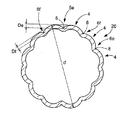
なお、この伝熱管2においては、山部4aから中心を通って管周上反対側に位置する山部4aに延びる伝熱管の直径(図2におけるd)が16mmであると共に、山部4aの曲率半径:Raが1.75mm、山部4bの曲率半径:Rbが2.05mm、山部4cの曲率半径:Rcが2.25mmとされ、また谷部6aの深さ:Daが0.9mm、谷部6bの深さ:Dbが0.7mm、谷部6cの深さ:Dcが0.5mm、谷部6dの深さ:Ddが0.3mmとされている。また、溝部8は、0.03mmの深さとされている。
【0030】
より詳細には、図2に示されているように、この伝熱管2は、その管周方向の所定領域に存在する複数の谷部が、その深さを漸減していると共に、該谷部の深さの漸減に対応して、前記山部の曲率半径が漸増せしめられているのである。即ち、ここで示された伝熱管は、管周の1/4周に亘って、その谷部の深さ:Da〜Ddが、Da>Db>Dc>Ddとなるようにされる一方、谷部間に形成されている山部の曲率半径:Ra〜Rcが、Ra<Rb<Rcとなるようにされているところから、その断面形状が、図2中において上下方向に短く、水平方向に長い、扁平断面形状となるようにされている。要するに、図2に示される伝熱管2は、その左右両側部に位置する谷部6dの深さが最も浅くされている一方、管の上下に位置する谷部6aの深さが最も深くされて、それらの間において深さが漸次変化せしめられているのである。また、山部の曲率半径にあっても、同様に、山部4aの曲率半径が最も小さく、山部4cの曲率半径が最も大きくなるように、漸次変化せしめられている。
【0031】
従って、かかる伝熱管2では、その管外表面に形成されている山部の曲率半径:Ra〜Rc及び谷部の深さ:Da〜Ddが、それぞれ相違せしめられているところから、干渉し合う山部4と谷部6の組み合わせによって、山部4及び谷部6のそれぞれにおいて発生するマランゴニー対流の干渉作用が異なり、吸収液の撹乱作用が有利に強められて、伝熱管表面の吸収液の撹拌が効果的に行なわれ、延いては伝熱管2の熱交換が効率的に行なわれ得るようにされているのである。
【0032】
また、この伝熱管2では、谷部6の底部のそれぞれに、図3に示される如き溝部8が設けられているところから、管外表面を流下せしめられる吸収液の液膜の厚さが不連続に変化せしめられ得て、山部及び谷部において発生するマランゴニー対流の干渉作用が有利に強められているのであり、以て伝熱性能の向上が効果的に図られ得るのである。しかも、かかる溝部8が、山部4ではなくて、谷部6に設けられているところから、山部4と谷部6とにおける液膜の厚さの差、延いてはマランゴニー対流の強さの差が、より一層大きくされ、その結果、吸収液の撹乱作用が有利に増強されるのである。
【0033】
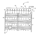
ところで、かかる伝熱管2は、一般には、図4に示されるように、吸収式冷凍機の吸収器10の内部に、略水平な姿勢で、鉛直方向に複数本並列するように配管され、そして該伝熱管2内に流通される冷却流体たる冷却水によって、管外表面の吸収液が冷却されるようになっているのである。即ち、この伝熱管2には、その上方に設けられたトレイ12の吸収液滴下孔14から、界面活性剤を含んだ臭化リチウム水溶液などの吸収液16が滴下または散布せしめられる。そして、滴下された吸収液16は、高濃度であるために、吸収器内に存在する水蒸気を吸収しながら、伝熱管2の外表面をスムーズに流下するのであり、その際に発生する熱を伝熱管2の内側に通される冷却水に伝熱することにより、冷却されるのである。そして、この管外表面を流下されるときに生ぜしめられるマランゴニー対流の強さが、相違せしめられているところから、吸収液16の撹乱作用が効果的に高められ得て、以て伝熱効率が有利に向上せしめられるのである。
【0034】
より詳細には、図5に示されるように、伝熱管2の上方に位置する吸収液滴下孔(図示せず)から滴下される吸収液16は、先ず、谷部6aにおいて伝熱管と接触し、次いで山部4aを越えて、順次、谷部6b、山部4b、谷部6c、山部4c、谷部6d、山部4c、谷部6c、・・・谷部6aと、管周を順に流下していき、山部4a〜4c或いは谷部6a〜6dのそれぞれにおいて、吸収液16の液膜の厚さに応じたマランゴニー対流が生じるのである。そして、その際、各谷部の深さ:Da〜Ddが順次浅くなるように変化しているところから、吸収液の液膜の厚さは、徐々に薄くなるため、各谷部において管軸方向に強さの異なるマランゴニー対流が発生する。また、各山部4a〜4cにおける吸収液の液膜の厚さは、谷部の場合に比べてかなり薄いために、山部4a〜4cにおいて管軸方向に比較的弱いマランゴニー対流が生じる。そして、山部4a〜4cと谷部6a〜6dのそれぞれで発生したマランゴニー対流が干渉し合うことにより、管軸方向に大きな撹乱作用が発生せしめられるのであるが、干渉し合うマランゴニー対流の組み合せによって、干渉の強さが異なるところから、吸収液の撹乱作用が著しく向上せしめられるのである。
【0035】
また、本実施例のように、吸収器内において、伝熱管2を、深さの最も深い谷部6aが管上下方向に位置するようにする一方、深さの最も浅い谷部6dを管の左右両側部に位置するようにして、それらの間において深さが漸次変化せしめられるように配置する、換言すればその断面形状が水平方向の方が長くなるように配置することにより、吸収液の見かけの流下速度を抑制することが出来、それにより、熱や物質の交換効率が大幅に向上せしめられているのである。
【0036】
さらに、本発明に従う構成の伝熱管2は、谷部6a〜6dに溝部8が形成されることにより、液膜の厚さが、各谷部において、より大きくなるように構成されているところから、通常運転時のように、吸収液が所定量滴下しているときに強いマランゴニー対流が発生するだけでなく、起動時などのように、滴下量が少ないときにも、溝部8に吸収液が集まって、所定の厚さを与えるところから、マランゴニー対流の強さを有利に高めることが出来、延いては伝熱性能を向上せしめ得るのである。なお、溝部8の深さは、0.03mmと小さく設定されており、その深さは小さなものであるために、吸収液の交換には問題がなく、伝熱管2の外表面での吸収液の管周方向への移動が速やかに行なわれる。そして、本発明に従う伝熱管2においては、従来から用いられている伝熱管と比較すると、溝部8に相当する吸収液を増加させるだけで、熱交換効率を効果的に向上せしめることが出来るのであり、更には、熱交換効率を高めた伝熱管と比較しても、吸収液の所要量が少なくても熱交換効率を改善することが出来て、管内の圧力損失を低減することが出来るのである。
【0037】
また、伝熱管2では、管内面が管外面に対応した曲面に形成されているところから、管内面への冷却流体中のスケールの付着を、効果的に防止し得ると共に、管内の清掃を容易ならしめたのである。
【0038】
また、図6には、本発明に従う吸収器用伝熱管の異なる実施例が示されている。即ち、ここで示された伝熱管18においては、山部4が、異なる曲率半径:Rd(=2.7mm)、Re(=3.3mm)を有する山部4d、4eからなり、それら山部4dと山部4eは、交互に配置されている。なお、伝熱管18の直径:dは、16mmであり、谷部6の深さは、0.6mmである。
【0039】
そして、かかる伝熱管18の外表面を吸収液16が流下せしめられる際には、山部4dでの吸収液の液膜の厚さが山部4eでの液膜の厚さより小さいために、、発生するマランゴニー対流の強さに差が生じ、また山部の曲率半径の違いにより、吸収液の流下速度が変化せしめられるのであり、しかも、それら4d、4eが管周方向において一つおきに配置されている。従って、山部4d或いは山部4eで発生するマランゴニー対流と谷部6で発生するマランゴニー対流との干渉作用が、有利に相違せしめられ、以て吸収液の撹乱作用が、延いては伝熱管18の伝熱性能が効果的に向上せしめられ得ているのである。
【0040】
さらに、図7には、本発明に従う吸収器用伝熱管の更に異なる実施例が示されている。即ち、ここで示された伝熱管20では、谷部6が、異なる深さ:De(=0.6mm)、Df(=0.3mm)を有する谷部6e、6fからなり、それら谷部6eと谷部6fは、交互に配置されている。なお、伝熱管20の直径:dは、16mmであり、山部4の曲率半径は、2.5mmである。
【0041】
そして、このような伝熱管20にあっても、その外表面に吸収液16が流下せしめられる際に、谷部6e及び谷部6fでの吸収液の液膜の厚さが異なり、発生するマランゴニー対流の強さが変化せしめられるのであり、しかも、それら谷部6e、6fが管周方向において一つおきに配置されている。従って、山部4で発生するマランゴニー対流と谷部6e或いは山部6fで発生するマランゴニー対流との干渉作用の強さに差が生じ、以て吸収液の撹乱作用、延いては伝熱管20の伝熱性能が効果的に向上せしめられ得るのである。
【0042】
【発明の効果】
以上の説明からも明らかなように、本発明に係る吸収器用伝熱管にあっては、山部で発生するマランゴニー対流と谷部で発生するマランゴニー対流との干渉作用が、干渉し合う山部と谷部の組み合わせによって、異なるようにされており、以て、従来の吸収器用伝熱管では得られなかった強い吸収液の撹乱作用が発揮され得て、管外表面での熱交換効率が効果的に向上せしめられ得るのである。そして、そのような熱交換効率の向上は、少なくとも隣り合う山部の曲率半径或いは少なくとも隣り合う谷部の深さを相違せしめることによって、より一層高められ得るのである。
【0043】
そして、本発明に係る吸収器用伝熱管では、熱交換効率が有利に向上せしめられていることにより、山部を多く形成したり、谷部を深く形成したりする必要もないのであり、従って、従来から公知の各種の方法、例えば冷間引抜き加工や異径管加工によって容易に製造出来るのであり、また管内の水頭損失を効果的に低減し得るのである。
【0044】
また、管外表面に流下せしめられる吸収液の撹乱作用をより増強するために、谷部の底部に、不連続面で連接する断面形状の溝部を設けた場合には、その不連続面の存在により、吸収液の撹乱作用が増強されると共に、吸収液の量が少ない場合でも、有利に液膜の厚さが確保されて、マランゴニー対流を効率的に発生させることが出来るため、吸収液の所要量を効果的に低減し得るのである。
【0045】
さらに、伝熱管において、管周方向の所定領域に存在する複数の谷部が、その深さを漸減せしめられていると共に、この谷部の深さの漸減に対応して、山部の曲率半径が漸増せしめられている場合に、その配設方向を考慮することにより、伝熱管に滴下された吸収液の見掛けの流下速度が抑制されるようになり、熱や物質の交換効率が大幅に向上せしめられ得るのである。
【図面の簡単な説明】
【図1】本発明に係る吸収器用伝熱管の一例を示す斜視説明図である。
【図2】図1に示される伝熱管の横断面説明図である。
【図3】図2に示される伝熱管断面の要部拡大説明図である。
【図4】図1に示される伝熱管の複数本を吸収器内へ配設した状態の一例を示す説明図である。
【図5】図4に示される吸収器における伝熱管の断面説明図である。
【図6】本発明に係る吸収器用伝熱管の異なる例を示す、図2と同様な横断面説明図である。
【図7】本発明に係る吸収器用伝熱管の更に異なる例を示す、図2と同様な横断面説明図である。
【符号の説明】
2、18、20 伝熱管 4、4a〜4e 山部
6、6a〜6f 谷部 8 溝部
10 吸収器 12 トレイ
14 吸収液滴下孔 16 吸収液[0001]
【Technical field】
The present invention relates to a heat transfer tube for an absorber piped in an absorber such as an absorption refrigerator or an absorption heat pump, and particularly has excellent heat exchange efficiency while keeping the pressure loss and the required amount of the absorption liquid in the tube low. The present invention relates to a heat transfer tube for an absorber.
[0002]
[Background Art]
Generally, as a heat transfer tube used in an absorber such as the absorption refrigerator or the absorption heat pump, a smooth tube having a circular cross section with smooth inner and outer surfaces is employed. However, since the heat transfer performance of such a smooth tube is low, it has been difficult to meet the demand for higher performance and smaller size of the absorber. Further, in such a smooth tube, the width of the absorbing liquid which is caused to flow down the outer peripheral surface of the tube in the circumferential direction of the tube is reduced due to surface tension, so that the effective heat exchange effect is exhibited. In addition, it is difficult to secure a required wet area, and there is also a problem that a thirst surface is easily generated on the outer surface of the tube, and the water vapor absorption rate of the absorbing solution, and thus the heat transfer performance, are reduced.
[0003]
In order to solve these problems, for example, a heat transfer tube having a configuration as disclosed in Japanese Utility Model Laid-Open No. 2-89270, Japanese Patent Laid-Open No. 2-176378, and the like has been proposed. That is, in the heat transfer tubes, a plurality of ridges extending in the longitudinal direction on the outer surface of the tubes and valleys formed between the ridges are formed with a curved surface shape continuous in the tube circumferential direction, and The radius of curvature of the valley is larger than the radius of curvature of the peak.
[0004]
In such a heat transfer tube, when used in a horizontal arrangement in the absorber, the absorbing liquid dropped or sprayed on the outer surface of the tube has a larger radius of curvature than the peak portion. By flowing smoothly to the valley, the replacement of the absorbing liquid at the valley becomes smooth, and by flowing uniformly over the entire circumference of the heat transfer tube, the Marangoni convection generated at the hill (including in the absorbing liquid) Convection caused by the surface tension difference due to the concentration distribution of the surfactant liquid film surface) and the Marangoni convection generated in the valley interfere with each other, and a large disturbance action occurs in the longitudinal direction, that is, in the tube axis direction. By doing so, heat exchange on the outer surface of the tube can be promoted, thereby improving the heat exchange efficiency.
[0005]
However, although the heat transfer tube having such a structure has improved heat transfer performance as compared with the smooth tube, it is difficult to form the peaks and valleys with ideal curved surfaces, and furthermore, the processing is difficult. There was a problem that the speed was slow.
[0006]
On the other hand, it is effective to reduce the number of peaks in the circumferential direction of the tube in order to reduce the manufacturing cost and improve the processing speed by simplifying the manufacture of the heat transfer tube. If the depth of the valley is increased to reduce the decrease in heat transfer performance, the head loss of the cooling water, which is the cooling fluid, will increase due to the decrease in the pipe cross-sectional area. Insufficient capacity of the pump or the stagnation of the absorbing liquid in the valley delays the progress of the absorbing liquid exchange, thereby reducing the heat exchange efficiency or further suppressing the heat exchange efficiency from decreasing. In addition, when a large number of heat transfer tubes are installed, a problem such as an increase in the required amount of filling of the absorbing liquid occurs.
[0007]
In the heat transfer tube as described above, the shape of the plurality of ridges formed in the longitudinal direction on the outer surface thereof is the same, and the depth of the valleys is the same. The thickness of the liquid film of the absorbing liquid flowing down in the circumferential direction, the flowing speed, and the effect of expanding the absorbing liquid in the tube axis direction at the valleys become substantially uniform. Therefore, since the interference between the Marangoni convections generated at the peaks and valleys is almost the same over the entire circumference of the heat transfer tube, there is also a problem that the disturbance effect of the absorbing liquid cannot be sufficiently obtained. I had it.
[0008]
[Solution]
Here, the present invention has been made in view of the above circumstances, and has as its object to have higher heat exchange efficiency, reduce pressure loss in the pipe, and fill the absorbing liquid. An object of the present invention is to provide a heat transfer tube for an absorber that can advantageously reduce a required amount.
[0009]
[Solution]
In order to solve such a problem, the present invention provides an absorbent in which the absorbing liquid is dropped or sprayed on the outer surface of the pipe, and the absorbing liquid outside the pipe is cooled by a cooling fluid such as cooling water in the pipe. In the heat transfer tube, a plurality of ridges extending in the tube axis direction on the outer surface of the tube are formed with a curved surface shape having an arc shape in the circumferential direction of the tube, and a radius of curvature of the ridges and / or a gap between the ridges are formed. The main point is that the depths of the valleys are different.
[0010]
That is, in such a heat transfer tube having the structure according to the present invention, the absorbing liquid such as the LiBr aqueous solution attached to the outer surface of the tube is effectively cast along the valley portion toward the tube axis direction. Therefore, it can be made to flow down in the circumferential direction of the pipe beyond each peak. At this time, since each peak is formed in an arcuate curved surface shape, the absorbent adhering to the surface of the heat transfer tube smoothly flows down over the peaks in the circumferential direction of the tube. It is possible to advantageously maintain the wet state of the surface of the peak portion, effectively prevent the deterioration of the heat transfer performance due to the generation of a so-called thirst surface, and at the same time, when the absorbent is allowed to flow down over the peak portion, Due to a change in the angle or the like, a disturbance and a convection phenomenon can be effectively caused in the absorbing solution, and a portion having a high concentration of the absorbing solution is well exposed to the outer surface, so that the action of absorbing water vapor is improved.
[0011]
Further, in such a heat transfer tube, Marangoni convection having different strength is formed along the peaks and valleys in the peaks and valleys formed on the outer surface thereof in proportion to the thickness of the liquid film of the absorbing liquid. Although the thickness of the liquid film of the absorbing liquid at the peak and the thickness of the liquid film of the absorbing liquid at the valley are significantly different, the strength of the Marangoni convection generated at the peak is The strength of Marangoni convection generated in the valley differs greatly. Then, the Marangoni convections having different intensities interfere with each other, so that the absorbing liquid is strongly disturbed.
[0012]
Further, in the heat transfer tube having the structure according to the present invention, since the radius of curvature of the peaks and / or the depth of the valleys are made different, between the peaks having different radii of curvature or the valleys having different depths. In the above, the thickness of the liquid film of the absorbing liquid is different, and the strength of the Marangoni convection generated there is also different, and the strength of the interference action of the Marangoni convection generated in the peaks and valleys as described above is reduced. It depends on the combination of peaks and valleys that interfere with each other. Therefore, the disturbance effect caused by the absorbing liquid becomes very strong, and the heat exchange efficiency is remarkably improved.
[0013]
By the way, according to the preferred embodiment of the heat transfer tube for an absorber according to the present invention, at least the depth of adjacent valleys and / or the radius of curvature of at least adjacent ridges are made different. In particular, by adopting such a configuration, when the absorbing liquid is caused to flow down the outer surface of the heat transfer tube, at least one of the repetition of the peak-valley-peak or the valley-peak-valley is performed. However, the strength of the interference effect of Marangoni convection is always made different, so that the strength of the interference action of Marangoni convection can be advantageously changed, and the disturbance of the absorbing solution can be performed more reliably. It is done.
[0014]
Further, according to a preferred aspect of the heat transfer tube for an absorber according to the present invention, a groove portion extending in the tube axis direction is provided at the bottom of the valley portion with a cross-sectional shape continuous with a discontinuous surface in the tube circumferential direction. . Then, due to the formation of such a groove, the thickness of the liquid film of the absorbing liquid is changed discontinuously in the circumferential direction of the tube at the formation portion of the groove, and thus occurs at each of the peak and the valley. The interference effect of Marangoni convection is greatly exaggerated. In addition, since such a groove is formed in the valley, the difference between the thickness of the liquid film of the absorbing liquid in the peak and the thickness of the liquid film of the absorbing liquid in the groove is further increased. Therefore, as in normal operation, when a predetermined amount of absorbing liquid is dripped, not only Marangoni convection is effectively generated, but also when the amount of dripping of the absorbing liquid is small at the time of startup or the like. Advantageously, the thickness of the liquid film is generated, and a disturbance effect due to effective Marangoni convection can be exerted, so that the heat transfer performance can be effectively improved. Since the depth of the groove is shallow, the replacement of the absorbing solution does not hinder the replacement of the absorbing solution at all, and the moving of the absorbing solution on the outer surface of the heat transfer tube in the circumferential direction of the tube is quickly performed. It is.
[0015]
Furthermore, according to another preferred embodiment of the heat transfer tube for an absorber according to the present invention, the plurality of valleys present in a predetermined region in the circumferential direction of the tube have their depths gradually reduced, and the depth of the valleys is reduced. In response to the gradual decrease, the radius of curvature of the peak is gradually increased. In the heat transfer tube having such a configuration, the flow rate of the absorbing liquid is advantageously suppressed by considering the directionality of the arrangement when piping in the absorber. The liquid is brought into contact with the outer surface of the heat transfer tube for a long time, and the heat transfer performance can be advantageously improved in combination with the various actions as described above. In addition, even when the amount of the absorbing liquid dropped is small, such as at the time of startup, since a sufficient liquid film thickness of the absorbing liquid is secured in the dropped valley, strong Marangoni convection occurs. Will be generated.
[0016]
BEST MODE FOR CARRYING OUT THE INVENTION
By the way, in such a heat exchanger tube for an absorber, a plurality of ridges extending in the tube axial direction on the outer surface thereof are formed with a curved surface shape having an arc shape in the circumferential direction of the tube, and a radius of curvature and / or The depths of the valleys formed between the peaks are made different. Even if the radii of curvature of the ridges or the depths of the valleys are made different in the entire circumferential direction of the pipe, one difference is obtained. Only the parts may be different. Then, in order to more effectively exert the disrupting action of the absorbing solution due to the interference of Marangoni convection, the curvature radius of at least the adjacent peaks or the depth of the valleys are made different, for example, the curvature radius of the peaks. Alternatively, it is desirable to arrange the valley depth so as to gradually increase or decrease, or to arrange two types of ridges having different radii of curvature or two types of valleys having different depths, respectively. It is.
[0017]
In addition, the number of the peaks in the pipe circumferential direction is not particularly limited, but is appropriately selected in consideration of the diameter of the heat transfer tube and the like. That is, if the number of peaks is too small, sufficient heat transfer performance cannot be obtained, and if it is too large, workability deteriorates. Therefore, the number of peaks is generally about 3 to 25 per pipe circumference. Is realized, the radius of curvature of the peak is set to about 0.5 mm to 5.0 mm.
[0018]
Further, the shape of the trough formed between the peaks is determined by the shape of the peak, and the depth of such a trough is usually 0.1 mm to 1.0 mm. To be on the order. This is because if the valley is too deep, the cross-sectional area of the heat transfer tube decreases, and the head loss increases. In the present invention, the depth of the valley is defined as a straight line that is in contact with the ridges adjacent to both sides of the valley from the bottom of the valley (or the bottom of the groove when a groove is provided at the bottom of the valley). Means the length of the vertical line.
[0019]
In the heat transfer tube for an absorber according to the present invention, it is preferable to form a groove at the bottom of the valley in order to further increase the disturbance action. It is formed so as to be connected in a discontinuous plane in the direction. In addition, the term “joining at a discontinuous surface” as used herein means that the outer peripheral surface of the crest and the valley and the outer peripheral surface of the groove at the intersection perpendicular to the tube axis direction at the intersection where there is no common tangent line. Is connected to.
[0020]
The cross-sectional shape of such a groove is not particularly limited, and various shapes such as an arc shape, a U shape, a V shape, a U shape, or a trapezoidal shape may be appropriately adopted. The depth is set to about 0.01 to 0.15 mm in order to prevent unnecessary retention of the absorbing liquid inside.
[0021]
By the way, as a material constituting such a heat transfer tube for an absorber, various known materials can be used, but in order to obtain a heat transfer tube having more excellent heat transfer performance, a material having excellent heat transfer properties, for example, It is desirable to use copper or copper alloy. The diameter of the obtained heat transfer tube is usually about 6.35 mm to 25.4 mm.
[0022]
The heat transfer tube for an absorber according to the present invention as described above is basically disclosed in Japanese Utility Model Laid-Open No. 2-89270, Japanese Patent Laid-Open No. 2-176378, Japanese Patent Laid-Open No. 7-24522 and the like. It will be manufactured according to a known method. Specifically, using a die having a die hole having a shape corresponding to the outer peripheral surface shape of the target heat transfer tube, that is, a shape corresponding to the peaks and valleys, a cylindrical processing tube made of copper or a copper alloy is cooled. It is manufactured by drawing or the like during hot or hot. Also, at this time, a plug is inserted into the pipe to be processed as necessary, so that the shape of the inner peripheral surface of the pipe is retained. Dice are also used as appropriate.
[0023]
Of course, the manufacture of the heat transfer tube according to the present invention is not limited to the method of manufacturing the heat transfer tube by cold or hot drawing as described above. It goes without saying that there is no problem with a method manufactured by extrusion, cold extrusion, or the like.
[0024]
Further, since the groove formed in each valley in the heat transfer tube according to the present invention is configured to be connected to the ridge and the valley via a discontinuous curved surface, the manufacturing method as described above uses a usual method. The combined use of the different-diameter pipe processing technology enables easy production and extremely excellent shape stability.
[0025]
Note that the peaks and valleys formed on the outer surface of the absorber heat transfer tube according to the present invention are not limited to those formed linearly in the tube axis direction as described above, and are not limited at all. Even if it is formed spirally in the axial direction, there is no problem. However, at that time, if the twist angle of the peak and the valley with respect to the pipe axis becomes too large, the amount of the absorbing liquid flowing down over the peak is reduced, and the heat transfer performance is reduced. Generally, it is desirable to set the angle to 15 ° or less.
[0026]
Further, such a heat transfer tube having a spiral ridge and a valley, by using a die having a spiral valley and a ridge, or while relatively rotating the cylindrical tube and the die as a pipe to be processed. It can be manufactured by performing a drawing process or the like.
[0027]
【Example】
Hereinafter, in order to clarify the present invention more specifically, embodiments of the present invention will be described. However, the present invention is not limited by the description of such embodiments. That goes without saying. In addition, in addition to the following examples, the present invention, in addition to the above-described specific description, various changes, modifications, and modifications based on the knowledge of those skilled in the art without departing from the spirit of the present invention. It should be understood that improvements and the like can be made.
[0028]
First, FIGS. 1 and 2 show a
[0029]
In this
[0030]
More specifically, as shown in FIG. 2, the
[0031]
Therefore, in such a
[0032]
Further, in this
[0033]
By the way, as shown in FIG. 4, such
[0034]
More specifically, as shown in FIG. 5, the absorbing
[0035]
Further, as in the present embodiment, in the absorber, the
[0036]
Further, since the
[0037]
Further, in the
[0038]
FIG. 6 shows another embodiment of the heat transfer tube for an absorber according to the present invention. That is, in the
[0039]
When the absorbing
[0040]
Further, FIG. 7 shows still another embodiment of the heat transfer tube for an absorber according to the present invention. That is, in the
[0041]
Even in such a
[0042]
【The invention's effect】
As is clear from the above description, in the heat transfer tube for an absorber according to the present invention, the interference between the Marangoni convection generated at the peak and the Marangoni convection generated at the valley causes the interference with the crest. Depending on the combination of the valleys, it is made different, so that a strong absorber disturbing action that could not be obtained with the conventional heat transfer tube for the absorber can be exhibited, and the heat exchange efficiency on the outer surface of the tube is effective Can be improved. Such improvement in heat exchange efficiency can be further enhanced by making at least the radius of curvature of adjacent peaks or the depth of at least adjacent valleys different.
[0043]
And, in the heat transfer tube for an absorber according to the present invention, since the heat exchange efficiency is advantageously improved, it is not necessary to form many ridges or to form valleys deeply. It can be easily manufactured by various conventionally known methods, for example, cold drawing and processing of different diameter pipes, and the head loss in the pipes can be effectively reduced.
[0044]
In addition, in order to further enhance the disturbing action of the absorbing liquid flowing down to the outer surface of the tube, when a groove having a cross-sectional shape connected by a discontinuous surface is provided at the bottom of the valley, the presence of the discontinuous surface is present. Thereby, the disturbing action of the absorbing solution is enhanced, and even when the amount of the absorbing solution is small, the thickness of the liquid film is advantageously secured, so that Marangoni convection can be efficiently generated. The required amount can be effectively reduced.
[0045]
Further, in the heat transfer tube, a plurality of valleys existing in a predetermined region in the circumferential direction of the tube are gradually reduced in depth, and the radii of curvature of the ridges are corresponding to the gradual decrease in the depth of the valleys. Considering the arrangement direction when the temperature is gradually increased, the apparent flow speed of the absorbing liquid dropped on the heat transfer tube will be suppressed, and the heat and substance exchange efficiency will be greatly improved. You can be sullen.
[Brief description of the drawings]
FIG. 1 is an explanatory perspective view showing an example of a heat transfer tube for an absorber according to the present invention.
FIG. 2 is an explanatory cross-sectional view of the heat transfer tube shown in FIG.
FIG. 3 is an enlarged explanatory view of a main part of a cross section of the heat transfer tube shown in FIG. 2;
FIG. 4 is an explanatory diagram showing an example of a state in which a plurality of heat transfer tubes shown in FIG. 1 are arranged in an absorber.
FIG. 5 is an explanatory sectional view of a heat transfer tube in the absorber shown in FIG.
FIG. 6 is a cross-sectional explanatory view similar to FIG. 2, showing a different example of the heat transfer tube for an absorber according to the present invention.
FIG. 7 is a cross-sectional explanatory view similar to FIG. 2, showing still another example of the heat transfer tube for an absorber according to the present invention.
[Explanation of symbols]
2, 18, 20
6, 6a to
10
14 Absorbing
Claims (5)
管外表面において管軸方向に延びる山部を、管周方向に円弧状の湾曲面形状をもって複数条形成すると共に、該山部の曲率半径及び/又は該山部間に形成される谷部の深さを相違せしめたことを特徴とする吸収器用伝熱管。Absorbent liquid is dropped or sprayed on the outer surface of the tube, and the cooling fluid in the tube is used to cool the absorbent outside the tube to a heat transfer tube for an absorber,
A plurality of ridges extending in the pipe axis direction on the outer pipe surface are formed with a curved surface shape having an arc shape in the circumferential direction of the pipe, and the radius of curvature of the ridges and / or A heat transfer tube for an absorber characterized by having different depths.
Priority Applications (1)
| Application Number | Priority Date | Filing Date | Title |
|---|---|---|---|
| JP26547895A JP3587599B2 (en) | 1995-10-13 | 1995-10-13 | Heat transfer tube for absorber |
Applications Claiming Priority (1)
| Application Number | Priority Date | Filing Date | Title |
|---|---|---|---|
| JP26547895A JP3587599B2 (en) | 1995-10-13 | 1995-10-13 | Heat transfer tube for absorber |
Publications (2)
| Publication Number | Publication Date |
|---|---|
| JPH09113164A JPH09113164A (en) | 1997-05-02 |
| JP3587599B2 true JP3587599B2 (en) | 2004-11-10 |
Family
ID=17417739
Family Applications (1)
| Application Number | Title | Priority Date | Filing Date |
|---|---|---|---|
| JP26547895A Expired - Fee Related JP3587599B2 (en) | 1995-10-13 | 1995-10-13 | Heat transfer tube for absorber |
Country Status (1)
| Country | Link |
|---|---|
| JP (1) | JP3587599B2 (en) |
Families Citing this family (4)
| Publication number | Priority date | Publication date | Assignee | Title |
|---|---|---|---|---|
| CN102374798A (en) * | 2010-08-11 | 2012-03-14 | 海尔集团公司 | Heat exchanger and energy-saving shower |
| CN102288059A (en) * | 2011-06-17 | 2011-12-21 | 苏州际能环境能源技术有限公司 | Special pipe of plum blossom spiral ground source heat pump ground heat exchanger |
| KR101708669B1 (en) * | 2014-12-04 | 2017-03-08 | 엘지전자 주식회사 | Stainless corrugate tube, Absorption refrigerating machine having the same and Manufacturing method of the same |
| CN111043406A (en) * | 2019-12-11 | 2020-04-21 | 宁波诺丁汉大学 | Vortex flow pipe |
-
1995
- 1995-10-13 JP JP26547895A patent/JP3587599B2/en not_active Expired - Fee Related
Also Published As
| Publication number | Publication date |
|---|---|
| JPH09113164A (en) | 1997-05-02 |
Similar Documents
| Publication | Publication Date | Title |
|---|---|---|
| CN109737793B (en) | Bionic wave type fin for air conditioner heat exchanger | |
| JP3315785B2 (en) | Heat transfer tube for absorber | |
| JP3769338B2 (en) | Heat exchanger tube for absorber and manufacturing method thereof | |
| JP2008261566A (en) | Double-pipe heat exchanger | |
| JP3587599B2 (en) | Heat transfer tube for absorber | |
| JP3916114B2 (en) | Absorption type refrigerator and heat transfer tube used therefor | |
| US4141411A (en) | Tubular heat exchanger | |
| JP2960828B2 (en) | Heat transfer tube for absorber | |
| JPH09113165A (en) | Heat transfer pipe for absorber | |
| JP3617538B2 (en) | Heat exchanger tube for absorber | |
| JPH09113066A (en) | Heat transfer tube for absorber | |
| JP3617537B2 (en) | Heat exchanger tube for absorber | |
| JP4587545B2 (en) | Heat exchanger tube for absorber | |
| JP2004003733A (en) | Heat transfer pipe and heat exchanger, and method of manufacture of heat transfer pipe | |
| CN212567061U (en) | Heat exchange tube fin, heat exchange tube and air conditioner | |
| JP3675498B2 (en) | Heat absorption tube for absorption refrigerator | |
| JPS62242795A (en) | Heat transfer tube | |
| JPH06159862A (en) | Absorber for freezer | |
| JP2000283678A (en) | Heat transfer pipe | |
| JPH1078268A (en) | Heat transfer tube | |
| JP2000304485A (en) | Heating tube for down-flow liquid film type heat exchanger | |
| KR100468397B1 (en) | A Falling Film Enhanced Tub | |
| JPH02137609A (en) | Heat exchanger tube for tube condensation and its manufacture | |
| KR100205977B1 (en) | Heaa pipe | |
| JPH11270980A (en) | Heat transfer pipe for evaporator |
Legal Events
| Date | Code | Title | Description |
|---|---|---|---|
| A977 | Report on retrieval |
Free format text: JAPANESE INTERMEDIATE CODE: A971007 Effective date: 20040728 |
|
| TRDD | Decision of grant or rejection written | ||
| A01 | Written decision to grant a patent or to grant a registration (utility model) |
Free format text: JAPANESE INTERMEDIATE CODE: A01 Effective date: 20040810 |
|
| A61 | First payment of annual fees (during grant procedure) |
Free format text: JAPANESE INTERMEDIATE CODE: A61 Effective date: 20040810 |
|
| R150 | Certificate of patent or registration of utility model |
Free format text: JAPANESE INTERMEDIATE CODE: R150 |
|
| FPAY | Renewal fee payment (event date is renewal date of database) |
Free format text: PAYMENT UNTIL: 20070820 Year of fee payment: 3 |
|
| FPAY | Renewal fee payment (event date is renewal date of database) |
Free format text: PAYMENT UNTIL: 20080820 Year of fee payment: 4 |
|
| FPAY | Renewal fee payment (event date is renewal date of database) |
Free format text: PAYMENT UNTIL: 20080820 Year of fee payment: 4 |
|
| FPAY | Renewal fee payment (event date is renewal date of database) |
Free format text: PAYMENT UNTIL: 20090820 Year of fee payment: 5 |
|
| LAPS | Cancellation because of no payment of annual fees |