JP3567992B2 - Head-neck femoral prosthesis - Google Patents
Head-neck femoral prosthesis Download PDFInfo
- Publication number
- JP3567992B2 JP3567992B2 JP50998798A JP50998798A JP3567992B2 JP 3567992 B2 JP3567992 B2 JP 3567992B2 JP 50998798 A JP50998798 A JP 50998798A JP 50998798 A JP50998798 A JP 50998798A JP 3567992 B2 JP3567992 B2 JP 3567992B2
- Authority
- JP
- Japan
- Prior art keywords
- bone
- artificial bone
- guide
- stem
- femur
- Prior art date
- Legal status (The legal status is an assumption and is not a legal conclusion. Google has not performed a legal analysis and makes no representation as to the accuracy of the status listed.)
- Expired - Fee Related
Links
Images


Classifications
-
- A—HUMAN NECESSITIES
- A61—MEDICAL OR VETERINARY SCIENCE; HYGIENE
- A61B—DIAGNOSIS; SURGERY; IDENTIFICATION
- A61B17/00—Surgical instruments, devices or methods, e.g. tourniquets
- A61B17/14—Surgical saws ; Accessories therefor
- A61B17/15—Guides therefor
-
- A—HUMAN NECESSITIES
- A61—MEDICAL OR VETERINARY SCIENCE; HYGIENE
- A61B—DIAGNOSIS; SURGERY; IDENTIFICATION
- A61B17/00—Surgical instruments, devices or methods, e.g. tourniquets
- A61B17/16—Bone cutting, breaking or removal means other than saws, e.g. Osteoclasts; Drills or chisels for bones; Trepans
- A61B17/1659—Surgical rasps, files, planes, or scrapers
-
- A—HUMAN NECESSITIES
- A61—MEDICAL OR VETERINARY SCIENCE; HYGIENE
- A61B—DIAGNOSIS; SURGERY; IDENTIFICATION
- A61B17/00—Surgical instruments, devices or methods, e.g. tourniquets
- A61B17/16—Bone cutting, breaking or removal means other than saws, e.g. Osteoclasts; Drills or chisels for bones; Trepans
- A61B17/1662—Bone cutting, breaking or removal means other than saws, e.g. Osteoclasts; Drills or chisels for bones; Trepans for particular parts of the body
- A61B17/1664—Bone cutting, breaking or removal means other than saws, e.g. Osteoclasts; Drills or chisels for bones; Trepans for particular parts of the body for the hip
- A61B17/1668—Bone cutting, breaking or removal means other than saws, e.g. Osteoclasts; Drills or chisels for bones; Trepans for particular parts of the body for the hip for the upper femur
-
- A—HUMAN NECESSITIES
- A61—MEDICAL OR VETERINARY SCIENCE; HYGIENE
- A61B—DIAGNOSIS; SURGERY; IDENTIFICATION
- A61B17/00—Surgical instruments, devices or methods, e.g. tourniquets
- A61B17/16—Bone cutting, breaking or removal means other than saws, e.g. Osteoclasts; Drills or chisels for bones; Trepans
- A61B17/17—Guides or aligning means for drills, mills, pins or wires
- A61B17/1739—Guides or aligning means for drills, mills, pins or wires specially adapted for particular parts of the body
- A61B17/1742—Guides or aligning means for drills, mills, pins or wires specially adapted for particular parts of the body for the hip
- A61B17/175—Guides or aligning means for drills, mills, pins or wires specially adapted for particular parts of the body for the hip for preparing the femur for hip prosthesis insertion
-
- A—HUMAN NECESSITIES
- A61—MEDICAL OR VETERINARY SCIENCE; HYGIENE
- A61F—FILTERS IMPLANTABLE INTO BLOOD VESSELS; PROSTHESES; DEVICES PROVIDING PATENCY TO, OR PREVENTING COLLAPSING OF, TUBULAR STRUCTURES OF THE BODY, e.g. STENTS; ORTHOPAEDIC, NURSING OR CONTRACEPTIVE DEVICES; FOMENTATION; TREATMENT OR PROTECTION OF EYES OR EARS; BANDAGES, DRESSINGS OR ABSORBENT PADS; FIRST-AID KITS
- A61F2/00—Filters implantable into blood vessels; Prostheses, i.e. artificial substitutes or replacements for parts of the body; Appliances for connecting them with the body; Devices providing patency to, or preventing collapsing of, tubular structures of the body, e.g. stents
- A61F2/02—Prostheses implantable into the body
- A61F2/30—Joints
- A61F2/32—Joints for the hip
- A61F2/36—Femoral heads ; Femoral endoprostheses
- A61F2/3601—Femoral heads ; Femoral endoprostheses for replacing only the epiphyseal or metaphyseal parts of the femur, e.g. endoprosthetic femoral heads or necks directly fixed to the natural femur by internal fixation devices
-
- A—HUMAN NECESSITIES
- A61—MEDICAL OR VETERINARY SCIENCE; HYGIENE
- A61F—FILTERS IMPLANTABLE INTO BLOOD VESSELS; PROSTHESES; DEVICES PROVIDING PATENCY TO, OR PREVENTING COLLAPSING OF, TUBULAR STRUCTURES OF THE BODY, e.g. STENTS; ORTHOPAEDIC, NURSING OR CONTRACEPTIVE DEVICES; FOMENTATION; TREATMENT OR PROTECTION OF EYES OR EARS; BANDAGES, DRESSINGS OR ABSORBENT PADS; FIRST-AID KITS
- A61F2/00—Filters implantable into blood vessels; Prostheses, i.e. artificial substitutes or replacements for parts of the body; Appliances for connecting them with the body; Devices providing patency to, or preventing collapsing of, tubular structures of the body, e.g. stents
- A61F2/02—Prostheses implantable into the body
- A61F2/30—Joints
- A61F2/32—Joints for the hip
- A61F2/36—Femoral heads ; Femoral endoprostheses
- A61F2/3662—Femoral shafts
- A61F2/367—Proximal or metaphyseal parts of shafts
-
- A—HUMAN NECESSITIES
- A61—MEDICAL OR VETERINARY SCIENCE; HYGIENE
- A61F—FILTERS IMPLANTABLE INTO BLOOD VESSELS; PROSTHESES; DEVICES PROVIDING PATENCY TO, OR PREVENTING COLLAPSING OF, TUBULAR STRUCTURES OF THE BODY, e.g. STENTS; ORTHOPAEDIC, NURSING OR CONTRACEPTIVE DEVICES; FOMENTATION; TREATMENT OR PROTECTION OF EYES OR EARS; BANDAGES, DRESSINGS OR ABSORBENT PADS; FIRST-AID KITS
- A61F2/00—Filters implantable into blood vessels; Prostheses, i.e. artificial substitutes or replacements for parts of the body; Appliances for connecting them with the body; Devices providing patency to, or preventing collapsing of, tubular structures of the body, e.g. stents
- A61F2/02—Prostheses implantable into the body
- A61F2/30—Joints
- A61F2/46—Special tools or methods for implanting or extracting artificial joints, accessories, bone grafts or substitutes, or particular adaptations therefor
- A61F2/4657—Measuring instruments used for implanting artificial joints
-
- A—HUMAN NECESSITIES
- A61—MEDICAL OR VETERINARY SCIENCE; HYGIENE
- A61B—DIAGNOSIS; SURGERY; IDENTIFICATION
- A61B10/00—Other methods or instruments for diagnosis, e.g. instruments for taking a cell sample, for biopsy, for vaccination diagnosis; Sex determination; Ovulation-period determination; Throat striking implements
- A61B10/02—Instruments for taking cell samples or for biopsy
-
- A—HUMAN NECESSITIES
- A61—MEDICAL OR VETERINARY SCIENCE; HYGIENE
- A61B—DIAGNOSIS; SURGERY; IDENTIFICATION
- A61B17/00—Surgical instruments, devices or methods, e.g. tourniquets
- A61B17/34—Trocars; Puncturing needles
- A61B17/3472—Trocars; Puncturing needles for bones, e.g. intraosseus injections
-
- A—HUMAN NECESSITIES
- A61—MEDICAL OR VETERINARY SCIENCE; HYGIENE
- A61B—DIAGNOSIS; SURGERY; IDENTIFICATION
- A61B17/00—Surgical instruments, devices or methods, e.g. tourniquets
- A61B17/56—Surgical instruments or methods for treatment of bones or joints; Devices specially adapted therefor
- A61B17/58—Surgical instruments or methods for treatment of bones or joints; Devices specially adapted therefor for osteosynthesis, e.g. bone plates, screws, setting implements or the like
- A61B17/68—Internal fixation devices, including fasteners and spinal fixators, even if a part thereof projects from the skin
- A61B17/74—Devices for the head or neck or trochanter of the femur
-
- A—HUMAN NECESSITIES
- A61—MEDICAL OR VETERINARY SCIENCE; HYGIENE
- A61B—DIAGNOSIS; SURGERY; IDENTIFICATION
- A61B17/00—Surgical instruments, devices or methods, e.g. tourniquets
- A61B17/56—Surgical instruments or methods for treatment of bones or joints; Devices specially adapted therefor
- A61B17/58—Surgical instruments or methods for treatment of bones or joints; Devices specially adapted therefor for osteosynthesis, e.g. bone plates, screws, setting implements or the like
- A61B17/88—Osteosynthesis instruments; Methods or means for implanting or extracting internal or external fixation devices
- A61B17/8875—Screwdrivers, spanners or wrenches
-
- A—HUMAN NECESSITIES
- A61—MEDICAL OR VETERINARY SCIENCE; HYGIENE
- A61B—DIAGNOSIS; SURGERY; IDENTIFICATION
- A61B17/00—Surgical instruments, devices or methods, e.g. tourniquets
- A61B17/32—Surgical cutting instruments
- A61B2017/320004—Surgical cutting instruments abrasive
- A61B2017/320012—Brushes
-
- A—HUMAN NECESSITIES
- A61—MEDICAL OR VETERINARY SCIENCE; HYGIENE
- A61B—DIAGNOSIS; SURGERY; IDENTIFICATION
- A61B90/00—Instruments, implements or accessories specially adapted for surgery or diagnosis and not covered by any of the groups A61B1/00 - A61B50/00, e.g. for luxation treatment or for protecting wound edges
- A61B90/03—Automatic limiting or abutting means, e.g. for safety
- A61B2090/033—Abutting means, stops, e.g. abutting on tissue or skin
- A61B2090/034—Abutting means, stops, e.g. abutting on tissue or skin abutting on parts of the device itself
-
- A—HUMAN NECESSITIES
- A61—MEDICAL OR VETERINARY SCIENCE; HYGIENE
- A61B—DIAGNOSIS; SURGERY; IDENTIFICATION
- A61B90/00—Instruments, implements or accessories specially adapted for surgery or diagnosis and not covered by any of the groups A61B1/00 - A61B50/00, e.g. for luxation treatment or for protecting wound edges
- A61B90/06—Measuring instruments not otherwise provided for
- A61B2090/067—Measuring instruments not otherwise provided for for measuring angles
-
- A—HUMAN NECESSITIES
- A61—MEDICAL OR VETERINARY SCIENCE; HYGIENE
- A61F—FILTERS IMPLANTABLE INTO BLOOD VESSELS; PROSTHESES; DEVICES PROVIDING PATENCY TO, OR PREVENTING COLLAPSING OF, TUBULAR STRUCTURES OF THE BODY, e.g. STENTS; ORTHOPAEDIC, NURSING OR CONTRACEPTIVE DEVICES; FOMENTATION; TREATMENT OR PROTECTION OF EYES OR EARS; BANDAGES, DRESSINGS OR ABSORBENT PADS; FIRST-AID KITS
- A61F2/00—Filters implantable into blood vessels; Prostheses, i.e. artificial substitutes or replacements for parts of the body; Appliances for connecting them with the body; Devices providing patency to, or preventing collapsing of, tubular structures of the body, e.g. stents
- A61F2/02—Prostheses implantable into the body
- A61F2/30—Joints
- A61F2/30767—Special external or bone-contacting surface, e.g. coating for improving bone ingrowth
-
- A—HUMAN NECESSITIES
- A61—MEDICAL OR VETERINARY SCIENCE; HYGIENE
- A61F—FILTERS IMPLANTABLE INTO BLOOD VESSELS; PROSTHESES; DEVICES PROVIDING PATENCY TO, OR PREVENTING COLLAPSING OF, TUBULAR STRUCTURES OF THE BODY, e.g. STENTS; ORTHOPAEDIC, NURSING OR CONTRACEPTIVE DEVICES; FOMENTATION; TREATMENT OR PROTECTION OF EYES OR EARS; BANDAGES, DRESSINGS OR ABSORBENT PADS; FIRST-AID KITS
- A61F2/00—Filters implantable into blood vessels; Prostheses, i.e. artificial substitutes or replacements for parts of the body; Appliances for connecting them with the body; Devices providing patency to, or preventing collapsing of, tubular structures of the body, e.g. stents
- A61F2/02—Prostheses implantable into the body
- A61F2/30—Joints
- A61F2/32—Joints for the hip
- A61F2/36—Femoral heads ; Femoral endoprostheses
- A61F2/3662—Femoral shafts
- A61F2/3676—Distal or diaphyseal parts of shafts
-
- A—HUMAN NECESSITIES
- A61—MEDICAL OR VETERINARY SCIENCE; HYGIENE
- A61F—FILTERS IMPLANTABLE INTO BLOOD VESSELS; PROSTHESES; DEVICES PROVIDING PATENCY TO, OR PREVENTING COLLAPSING OF, TUBULAR STRUCTURES OF THE BODY, e.g. STENTS; ORTHOPAEDIC, NURSING OR CONTRACEPTIVE DEVICES; FOMENTATION; TREATMENT OR PROTECTION OF EYES OR EARS; BANDAGES, DRESSINGS OR ABSORBENT PADS; FIRST-AID KITS
- A61F2/00—Filters implantable into blood vessels; Prostheses, i.e. artificial substitutes or replacements for parts of the body; Appliances for connecting them with the body; Devices providing patency to, or preventing collapsing of, tubular structures of the body, e.g. stents
- A61F2/02—Prostheses implantable into the body
- A61F2/30—Joints
- A61F2/46—Special tools or methods for implanting or extracting artificial joints, accessories, bone grafts or substitutes, or particular adaptations therefor
- A61F2/4603—Special tools or methods for implanting or extracting artificial joints, accessories, bone grafts or substitutes, or particular adaptations therefor for insertion or extraction of endoprosthetic joints or of accessories thereof
- A61F2/4607—Special tools or methods for implanting or extracting artificial joints, accessories, bone grafts or substitutes, or particular adaptations therefor for insertion or extraction of endoprosthetic joints or of accessories thereof of hip femoral endoprostheses
-
- A—HUMAN NECESSITIES
- A61—MEDICAL OR VETERINARY SCIENCE; HYGIENE
- A61F—FILTERS IMPLANTABLE INTO BLOOD VESSELS; PROSTHESES; DEVICES PROVIDING PATENCY TO, OR PREVENTING COLLAPSING OF, TUBULAR STRUCTURES OF THE BODY, e.g. STENTS; ORTHOPAEDIC, NURSING OR CONTRACEPTIVE DEVICES; FOMENTATION; TREATMENT OR PROTECTION OF EYES OR EARS; BANDAGES, DRESSINGS OR ABSORBENT PADS; FIRST-AID KITS
- A61F2/00—Filters implantable into blood vessels; Prostheses, i.e. artificial substitutes or replacements for parts of the body; Appliances for connecting them with the body; Devices providing patency to, or preventing collapsing of, tubular structures of the body, e.g. stents
- A61F2/02—Prostheses implantable into the body
- A61F2/30—Joints
- A61F2/46—Special tools or methods for implanting or extracting artificial joints, accessories, bone grafts or substitutes, or particular adaptations therefor
- A61F2/4684—Trial or dummy prostheses
-
- A—HUMAN NECESSITIES
- A61—MEDICAL OR VETERINARY SCIENCE; HYGIENE
- A61F—FILTERS IMPLANTABLE INTO BLOOD VESSELS; PROSTHESES; DEVICES PROVIDING PATENCY TO, OR PREVENTING COLLAPSING OF, TUBULAR STRUCTURES OF THE BODY, e.g. STENTS; ORTHOPAEDIC, NURSING OR CONTRACEPTIVE DEVICES; FOMENTATION; TREATMENT OR PROTECTION OF EYES OR EARS; BANDAGES, DRESSINGS OR ABSORBENT PADS; FIRST-AID KITS
- A61F2/00—Filters implantable into blood vessels; Prostheses, i.e. artificial substitutes or replacements for parts of the body; Appliances for connecting them with the body; Devices providing patency to, or preventing collapsing of, tubular structures of the body, e.g. stents
- A61F2/02—Prostheses implantable into the body
- A61F2/30—Joints
- A61F2002/30001—Additional features of subject-matter classified in A61F2/28, A61F2/30 and subgroups thereof
- A61F2002/30108—Shapes
- A61F2002/3011—Cross-sections or two-dimensional shapes
- A61F2002/30159—Concave polygonal shapes
- A61F2002/30171—Concave polygonal shapes rosette- or star-shaped
-
- A—HUMAN NECESSITIES
- A61—MEDICAL OR VETERINARY SCIENCE; HYGIENE
- A61F—FILTERS IMPLANTABLE INTO BLOOD VESSELS; PROSTHESES; DEVICES PROVIDING PATENCY TO, OR PREVENTING COLLAPSING OF, TUBULAR STRUCTURES OF THE BODY, e.g. STENTS; ORTHOPAEDIC, NURSING OR CONTRACEPTIVE DEVICES; FOMENTATION; TREATMENT OR PROTECTION OF EYES OR EARS; BANDAGES, DRESSINGS OR ABSORBENT PADS; FIRST-AID KITS
- A61F2/00—Filters implantable into blood vessels; Prostheses, i.e. artificial substitutes or replacements for parts of the body; Appliances for connecting them with the body; Devices providing patency to, or preventing collapsing of, tubular structures of the body, e.g. stents
- A61F2/02—Prostheses implantable into the body
- A61F2/30—Joints
- A61F2002/30001—Additional features of subject-matter classified in A61F2/28, A61F2/30 and subgroups thereof
- A61F2002/30316—The prosthesis having different structural features at different locations within the same prosthesis; Connections between prosthetic parts; Special structural features of bone or joint prostheses not otherwise provided for
- A61F2002/30317—The prosthesis having different structural features at different locations within the same prosthesis
- A61F2002/30322—The prosthesis having different structural features at different locations within the same prosthesis differing in surface structures
-
- A—HUMAN NECESSITIES
- A61—MEDICAL OR VETERINARY SCIENCE; HYGIENE
- A61F—FILTERS IMPLANTABLE INTO BLOOD VESSELS; PROSTHESES; DEVICES PROVIDING PATENCY TO, OR PREVENTING COLLAPSING OF, TUBULAR STRUCTURES OF THE BODY, e.g. STENTS; ORTHOPAEDIC, NURSING OR CONTRACEPTIVE DEVICES; FOMENTATION; TREATMENT OR PROTECTION OF EYES OR EARS; BANDAGES, DRESSINGS OR ABSORBENT PADS; FIRST-AID KITS
- A61F2/00—Filters implantable into blood vessels; Prostheses, i.e. artificial substitutes or replacements for parts of the body; Appliances for connecting them with the body; Devices providing patency to, or preventing collapsing of, tubular structures of the body, e.g. stents
- A61F2/02—Prostheses implantable into the body
- A61F2/30—Joints
- A61F2002/30001—Additional features of subject-matter classified in A61F2/28, A61F2/30 and subgroups thereof
- A61F2002/30316—The prosthesis having different structural features at different locations within the same prosthesis; Connections between prosthetic parts; Special structural features of bone or joint prostheses not otherwise provided for
- A61F2002/30329—Connections or couplings between prosthetic parts, e.g. between modular parts; Connecting elements
- A61F2002/30331—Connections or couplings between prosthetic parts, e.g. between modular parts; Connecting elements made by longitudinally pushing a protrusion into a complementarily-shaped recess, e.g. held by friction fit
- A61F2002/30354—Cylindrically-shaped protrusion and recess, e.g. cylinder of circular basis
-
- A—HUMAN NECESSITIES
- A61—MEDICAL OR VETERINARY SCIENCE; HYGIENE
- A61F—FILTERS IMPLANTABLE INTO BLOOD VESSELS; PROSTHESES; DEVICES PROVIDING PATENCY TO, OR PREVENTING COLLAPSING OF, TUBULAR STRUCTURES OF THE BODY, e.g. STENTS; ORTHOPAEDIC, NURSING OR CONTRACEPTIVE DEVICES; FOMENTATION; TREATMENT OR PROTECTION OF EYES OR EARS; BANDAGES, DRESSINGS OR ABSORBENT PADS; FIRST-AID KITS
- A61F2/00—Filters implantable into blood vessels; Prostheses, i.e. artificial substitutes or replacements for parts of the body; Appliances for connecting them with the body; Devices providing patency to, or preventing collapsing of, tubular structures of the body, e.g. stents
- A61F2/02—Prostheses implantable into the body
- A61F2/30—Joints
- A61F2002/30001—Additional features of subject-matter classified in A61F2/28, A61F2/30 and subgroups thereof
- A61F2002/30316—The prosthesis having different structural features at different locations within the same prosthesis; Connections between prosthetic parts; Special structural features of bone or joint prostheses not otherwise provided for
- A61F2002/30535—Special structural features of bone or joint prostheses not otherwise provided for
- A61F2002/30594—Special structural features of bone or joint prostheses not otherwise provided for slotted, e.g. radial or meridian slot ending in a polar aperture, non-polar slots, horizontal or arcuate slots
-
- A—HUMAN NECESSITIES
- A61—MEDICAL OR VETERINARY SCIENCE; HYGIENE
- A61F—FILTERS IMPLANTABLE INTO BLOOD VESSELS; PROSTHESES; DEVICES PROVIDING PATENCY TO, OR PREVENTING COLLAPSING OF, TUBULAR STRUCTURES OF THE BODY, e.g. STENTS; ORTHOPAEDIC, NURSING OR CONTRACEPTIVE DEVICES; FOMENTATION; TREATMENT OR PROTECTION OF EYES OR EARS; BANDAGES, DRESSINGS OR ABSORBENT PADS; FIRST-AID KITS
- A61F2/00—Filters implantable into blood vessels; Prostheses, i.e. artificial substitutes or replacements for parts of the body; Appliances for connecting them with the body; Devices providing patency to, or preventing collapsing of, tubular structures of the body, e.g. stents
- A61F2/02—Prostheses implantable into the body
- A61F2/30—Joints
- A61F2002/30001—Additional features of subject-matter classified in A61F2/28, A61F2/30 and subgroups thereof
- A61F2002/30667—Features concerning an interaction with the environment or a particular use of the prosthesis
- A61F2002/30677—Means for introducing or releasing pharmaceutical products, e.g. antibiotics, into the body
-
- A—HUMAN NECESSITIES
- A61—MEDICAL OR VETERINARY SCIENCE; HYGIENE
- A61F—FILTERS IMPLANTABLE INTO BLOOD VESSELS; PROSTHESES; DEVICES PROVIDING PATENCY TO, OR PREVENTING COLLAPSING OF, TUBULAR STRUCTURES OF THE BODY, e.g. STENTS; ORTHOPAEDIC, NURSING OR CONTRACEPTIVE DEVICES; FOMENTATION; TREATMENT OR PROTECTION OF EYES OR EARS; BANDAGES, DRESSINGS OR ABSORBENT PADS; FIRST-AID KITS
- A61F2/00—Filters implantable into blood vessels; Prostheses, i.e. artificial substitutes or replacements for parts of the body; Appliances for connecting them with the body; Devices providing patency to, or preventing collapsing of, tubular structures of the body, e.g. stents
- A61F2/02—Prostheses implantable into the body
- A61F2/30—Joints
- A61F2002/30001—Additional features of subject-matter classified in A61F2/28, A61F2/30 and subgroups thereof
- A61F2002/30667—Features concerning an interaction with the environment or a particular use of the prosthesis
- A61F2002/30682—Means for preventing migration of particles released by the joint, e.g. wear debris or cement particles
-
- A—HUMAN NECESSITIES
- A61—MEDICAL OR VETERINARY SCIENCE; HYGIENE
- A61F—FILTERS IMPLANTABLE INTO BLOOD VESSELS; PROSTHESES; DEVICES PROVIDING PATENCY TO, OR PREVENTING COLLAPSING OF, TUBULAR STRUCTURES OF THE BODY, e.g. STENTS; ORTHOPAEDIC, NURSING OR CONTRACEPTIVE DEVICES; FOMENTATION; TREATMENT OR PROTECTION OF EYES OR EARS; BANDAGES, DRESSINGS OR ABSORBENT PADS; FIRST-AID KITS
- A61F2/00—Filters implantable into blood vessels; Prostheses, i.e. artificial substitutes or replacements for parts of the body; Appliances for connecting them with the body; Devices providing patency to, or preventing collapsing of, tubular structures of the body, e.g. stents
- A61F2/02—Prostheses implantable into the body
- A61F2/30—Joints
- A61F2/30721—Accessories
- A61F2/30724—Spacers for centering an implant in a bone cavity, e.g. in a cement-receiving cavity
- A61F2002/30726—Centering or guiding rods, e.g. for insertion of femoral shafts
-
- A—HUMAN NECESSITIES
- A61—MEDICAL OR VETERINARY SCIENCE; HYGIENE
- A61F—FILTERS IMPLANTABLE INTO BLOOD VESSELS; PROSTHESES; DEVICES PROVIDING PATENCY TO, OR PREVENTING COLLAPSING OF, TUBULAR STRUCTURES OF THE BODY, e.g. STENTS; ORTHOPAEDIC, NURSING OR CONTRACEPTIVE DEVICES; FOMENTATION; TREATMENT OR PROTECTION OF EYES OR EARS; BANDAGES, DRESSINGS OR ABSORBENT PADS; FIRST-AID KITS
- A61F2/00—Filters implantable into blood vessels; Prostheses, i.e. artificial substitutes or replacements for parts of the body; Appliances for connecting them with the body; Devices providing patency to, or preventing collapsing of, tubular structures of the body, e.g. stents
- A61F2/02—Prostheses implantable into the body
- A61F2/30—Joints
- A61F2/30767—Special external or bone-contacting surface, e.g. coating for improving bone ingrowth
- A61F2/30771—Special external or bone-contacting surface, e.g. coating for improving bone ingrowth applied in original prostheses, e.g. holes or grooves
- A61F2002/3082—Grooves
-
- A—HUMAN NECESSITIES
- A61—MEDICAL OR VETERINARY SCIENCE; HYGIENE
- A61F—FILTERS IMPLANTABLE INTO BLOOD VESSELS; PROSTHESES; DEVICES PROVIDING PATENCY TO, OR PREVENTING COLLAPSING OF, TUBULAR STRUCTURES OF THE BODY, e.g. STENTS; ORTHOPAEDIC, NURSING OR CONTRACEPTIVE DEVICES; FOMENTATION; TREATMENT OR PROTECTION OF EYES OR EARS; BANDAGES, DRESSINGS OR ABSORBENT PADS; FIRST-AID KITS
- A61F2/00—Filters implantable into blood vessels; Prostheses, i.e. artificial substitutes or replacements for parts of the body; Appliances for connecting them with the body; Devices providing patency to, or preventing collapsing of, tubular structures of the body, e.g. stents
- A61F2/02—Prostheses implantable into the body
- A61F2/30—Joints
- A61F2/32—Joints for the hip
- A61F2/36—Femoral heads ; Femoral endoprostheses
- A61F2/3609—Femoral heads or necks; Connections of endoprosthetic heads or necks to endoprosthetic femoral shafts
- A61F2002/3625—Necks
- A61F2002/3631—Necks with an integral complete or partial peripheral collar or bearing shoulder at its base
-
- A—HUMAN NECESSITIES
- A61—MEDICAL OR VETERINARY SCIENCE; HYGIENE
- A61F—FILTERS IMPLANTABLE INTO BLOOD VESSELS; PROSTHESES; DEVICES PROVIDING PATENCY TO, OR PREVENTING COLLAPSING OF, TUBULAR STRUCTURES OF THE BODY, e.g. STENTS; ORTHOPAEDIC, NURSING OR CONTRACEPTIVE DEVICES; FOMENTATION; TREATMENT OR PROTECTION OF EYES OR EARS; BANDAGES, DRESSINGS OR ABSORBENT PADS; FIRST-AID KITS
- A61F2/00—Filters implantable into blood vessels; Prostheses, i.e. artificial substitutes or replacements for parts of the body; Appliances for connecting them with the body; Devices providing patency to, or preventing collapsing of, tubular structures of the body, e.g. stents
- A61F2/02—Prostheses implantable into the body
- A61F2/30—Joints
- A61F2/32—Joints for the hip
- A61F2/36—Femoral heads ; Femoral endoprostheses
- A61F2/3609—Femoral heads or necks; Connections of endoprosthetic heads or necks to endoprosthetic femoral shafts
- A61F2002/365—Connections of heads to necks
-
- A—HUMAN NECESSITIES
- A61—MEDICAL OR VETERINARY SCIENCE; HYGIENE
- A61F—FILTERS IMPLANTABLE INTO BLOOD VESSELS; PROSTHESES; DEVICES PROVIDING PATENCY TO, OR PREVENTING COLLAPSING OF, TUBULAR STRUCTURES OF THE BODY, e.g. STENTS; ORTHOPAEDIC, NURSING OR CONTRACEPTIVE DEVICES; FOMENTATION; TREATMENT OR PROTECTION OF EYES OR EARS; BANDAGES, DRESSINGS OR ABSORBENT PADS; FIRST-AID KITS
- A61F2/00—Filters implantable into blood vessels; Prostheses, i.e. artificial substitutes or replacements for parts of the body; Appliances for connecting them with the body; Devices providing patency to, or preventing collapsing of, tubular structures of the body, e.g. stents
- A61F2/02—Prostheses implantable into the body
- A61F2/30—Joints
- A61F2/32—Joints for the hip
- A61F2/36—Femoral heads ; Femoral endoprostheses
- A61F2/3662—Femoral shafts
- A61F2002/3678—Geometrical features
- A61F2002/368—Geometrical features with lateral apertures, bores, holes or openings, e.g. for reducing the mass, for receiving fixation screws or for communicating with the inside of a hollow shaft
-
- A—HUMAN NECESSITIES
- A61—MEDICAL OR VETERINARY SCIENCE; HYGIENE
- A61F—FILTERS IMPLANTABLE INTO BLOOD VESSELS; PROSTHESES; DEVICES PROVIDING PATENCY TO, OR PREVENTING COLLAPSING OF, TUBULAR STRUCTURES OF THE BODY, e.g. STENTS; ORTHOPAEDIC, NURSING OR CONTRACEPTIVE DEVICES; FOMENTATION; TREATMENT OR PROTECTION OF EYES OR EARS; BANDAGES, DRESSINGS OR ABSORBENT PADS; FIRST-AID KITS
- A61F2/00—Filters implantable into blood vessels; Prostheses, i.e. artificial substitutes or replacements for parts of the body; Appliances for connecting them with the body; Devices providing patency to, or preventing collapsing of, tubular structures of the body, e.g. stents
- A61F2/02—Prostheses implantable into the body
- A61F2/30—Joints
- A61F2/32—Joints for the hip
- A61F2/36—Femoral heads ; Femoral endoprostheses
- A61F2/3662—Femoral shafts
- A61F2002/3678—Geometrical features
- A61F2002/3694—Geometrical features with longitudinal bores
-
- A—HUMAN NECESSITIES
- A61—MEDICAL OR VETERINARY SCIENCE; HYGIENE
- A61F—FILTERS IMPLANTABLE INTO BLOOD VESSELS; PROSTHESES; DEVICES PROVIDING PATENCY TO, OR PREVENTING COLLAPSING OF, TUBULAR STRUCTURES OF THE BODY, e.g. STENTS; ORTHOPAEDIC, NURSING OR CONTRACEPTIVE DEVICES; FOMENTATION; TREATMENT OR PROTECTION OF EYES OR EARS; BANDAGES, DRESSINGS OR ABSORBENT PADS; FIRST-AID KITS
- A61F2/00—Filters implantable into blood vessels; Prostheses, i.e. artificial substitutes or replacements for parts of the body; Appliances for connecting them with the body; Devices providing patency to, or preventing collapsing of, tubular structures of the body, e.g. stents
- A61F2/02—Prostheses implantable into the body
- A61F2/30—Joints
- A61F2/46—Special tools or methods for implanting or extracting artificial joints, accessories, bone grafts or substitutes, or particular adaptations therefor
- A61F2002/4635—Special tools or methods for implanting or extracting artificial joints, accessories, bone grafts or substitutes, or particular adaptations therefor using minimally invasive surgery
-
- A—HUMAN NECESSITIES
- A61—MEDICAL OR VETERINARY SCIENCE; HYGIENE
- A61F—FILTERS IMPLANTABLE INTO BLOOD VESSELS; PROSTHESES; DEVICES PROVIDING PATENCY TO, OR PREVENTING COLLAPSING OF, TUBULAR STRUCTURES OF THE BODY, e.g. STENTS; ORTHOPAEDIC, NURSING OR CONTRACEPTIVE DEVICES; FOMENTATION; TREATMENT OR PROTECTION OF EYES OR EARS; BANDAGES, DRESSINGS OR ABSORBENT PADS; FIRST-AID KITS
- A61F2/00—Filters implantable into blood vessels; Prostheses, i.e. artificial substitutes or replacements for parts of the body; Appliances for connecting them with the body; Devices providing patency to, or preventing collapsing of, tubular structures of the body, e.g. stents
- A61F2/02—Prostheses implantable into the body
- A61F2/30—Joints
- A61F2/46—Special tools or methods for implanting or extracting artificial joints, accessories, bone grafts or substitutes, or particular adaptations therefor
- A61F2/4657—Measuring instruments used for implanting artificial joints
- A61F2002/4668—Measuring instruments used for implanting artificial joints for measuring angles
-
- A—HUMAN NECESSITIES
- A61—MEDICAL OR VETERINARY SCIENCE; HYGIENE
- A61F—FILTERS IMPLANTABLE INTO BLOOD VESSELS; PROSTHESES; DEVICES PROVIDING PATENCY TO, OR PREVENTING COLLAPSING OF, TUBULAR STRUCTURES OF THE BODY, e.g. STENTS; ORTHOPAEDIC, NURSING OR CONTRACEPTIVE DEVICES; FOMENTATION; TREATMENT OR PROTECTION OF EYES OR EARS; BANDAGES, DRESSINGS OR ABSORBENT PADS; FIRST-AID KITS
- A61F2/00—Filters implantable into blood vessels; Prostheses, i.e. artificial substitutes or replacements for parts of the body; Appliances for connecting them with the body; Devices providing patency to, or preventing collapsing of, tubular structures of the body, e.g. stents
- A61F2/02—Prostheses implantable into the body
- A61F2/30—Joints
- A61F2/46—Special tools or methods for implanting or extracting artificial joints, accessories, bone grafts or substitutes, or particular adaptations therefor
- A61F2002/4677—Special tools or methods for implanting or extracting artificial joints, accessories, bone grafts or substitutes, or particular adaptations therefor using a guide wire
-
- A—HUMAN NECESSITIES
- A61—MEDICAL OR VETERINARY SCIENCE; HYGIENE
- A61F—FILTERS IMPLANTABLE INTO BLOOD VESSELS; PROSTHESES; DEVICES PROVIDING PATENCY TO, OR PREVENTING COLLAPSING OF, TUBULAR STRUCTURES OF THE BODY, e.g. STENTS; ORTHOPAEDIC, NURSING OR CONTRACEPTIVE DEVICES; FOMENTATION; TREATMENT OR PROTECTION OF EYES OR EARS; BANDAGES, DRESSINGS OR ABSORBENT PADS; FIRST-AID KITS
- A61F2220/00—Fixations or connections for prostheses classified in groups A61F2/00 - A61F2/26 or A61F2/82 or A61F9/00 or A61F11/00 or subgroups thereof
- A61F2220/0025—Connections or couplings between prosthetic parts, e.g. between modular parts; Connecting elements
- A61F2220/0033—Connections or couplings between prosthetic parts, e.g. between modular parts; Connecting elements made by longitudinally pushing a protrusion into a complementary-shaped recess, e.g. held by friction fit
-
- A—HUMAN NECESSITIES
- A61—MEDICAL OR VETERINARY SCIENCE; HYGIENE
- A61F—FILTERS IMPLANTABLE INTO BLOOD VESSELS; PROSTHESES; DEVICES PROVIDING PATENCY TO, OR PREVENTING COLLAPSING OF, TUBULAR STRUCTURES OF THE BODY, e.g. STENTS; ORTHOPAEDIC, NURSING OR CONTRACEPTIVE DEVICES; FOMENTATION; TREATMENT OR PROTECTION OF EYES OR EARS; BANDAGES, DRESSINGS OR ABSORBENT PADS; FIRST-AID KITS
- A61F2230/00—Geometry of prostheses classified in groups A61F2/00 - A61F2/26 or A61F2/82 or A61F9/00 or A61F11/00 or subgroups thereof
- A61F2230/0002—Two-dimensional shapes, e.g. cross-sections
- A61F2230/0028—Shapes in the form of latin or greek characters
- A61F2230/005—Rosette-shaped, e.g. star-shaped
-
- A—HUMAN NECESSITIES
- A61—MEDICAL OR VETERINARY SCIENCE; HYGIENE
- A61F—FILTERS IMPLANTABLE INTO BLOOD VESSELS; PROSTHESES; DEVICES PROVIDING PATENCY TO, OR PREVENTING COLLAPSING OF, TUBULAR STRUCTURES OF THE BODY, e.g. STENTS; ORTHOPAEDIC, NURSING OR CONTRACEPTIVE DEVICES; FOMENTATION; TREATMENT OR PROTECTION OF EYES OR EARS; BANDAGES, DRESSINGS OR ABSORBENT PADS; FIRST-AID KITS
- A61F2250/00—Special features of prostheses classified in groups A61F2/00 - A61F2/26 or A61F2/82 or A61F9/00 or A61F11/00 or subgroups thereof
- A61F2250/0014—Special features of prostheses classified in groups A61F2/00 - A61F2/26 or A61F2/82 or A61F9/00 or A61F11/00 or subgroups thereof having different values of a given property or geometrical feature, e.g. mechanical property or material property, at different locations within the same prosthesis
- A61F2250/0026—Special features of prostheses classified in groups A61F2/00 - A61F2/26 or A61F2/82 or A61F9/00 or A61F11/00 or subgroups thereof having different values of a given property or geometrical feature, e.g. mechanical property or material property, at different locations within the same prosthesis differing in surface structures
-
- A—HUMAN NECESSITIES
- A61—MEDICAL OR VETERINARY SCIENCE; HYGIENE
- A61F—FILTERS IMPLANTABLE INTO BLOOD VESSELS; PROSTHESES; DEVICES PROVIDING PATENCY TO, OR PREVENTING COLLAPSING OF, TUBULAR STRUCTURES OF THE BODY, e.g. STENTS; ORTHOPAEDIC, NURSING OR CONTRACEPTIVE DEVICES; FOMENTATION; TREATMENT OR PROTECTION OF EYES OR EARS; BANDAGES, DRESSINGS OR ABSORBENT PADS; FIRST-AID KITS
- A61F2310/00—Prostheses classified in A61F2/28 or A61F2/30 - A61F2/44 being constructed from or coated with a particular material
- A61F2310/00005—The prosthesis being constructed from a particular material
- A61F2310/00011—Metals or alloys
- A61F2310/00023—Titanium or titanium-based alloys, e.g. Ti-Ni alloys
-
- A—HUMAN NECESSITIES
- A61—MEDICAL OR VETERINARY SCIENCE; HYGIENE
- A61F—FILTERS IMPLANTABLE INTO BLOOD VESSELS; PROSTHESES; DEVICES PROVIDING PATENCY TO, OR PREVENTING COLLAPSING OF, TUBULAR STRUCTURES OF THE BODY, e.g. STENTS; ORTHOPAEDIC, NURSING OR CONTRACEPTIVE DEVICES; FOMENTATION; TREATMENT OR PROTECTION OF EYES OR EARS; BANDAGES, DRESSINGS OR ABSORBENT PADS; FIRST-AID KITS
- A61F2310/00—Prostheses classified in A61F2/28 or A61F2/30 - A61F2/44 being constructed from or coated with a particular material
- A61F2310/00005—The prosthesis being constructed from a particular material
- A61F2310/00011—Metals or alloys
- A61F2310/00029—Cobalt-based alloys, e.g. Co-Cr alloys or Vitallium
Abstract
Description
本願出願は、米国特許出願第60/023,398号の一部継続出願であり、これはここに一体のものとして統合される。
発明の背景
本発明は、一般に、ヘッド−ネック大腿人工骨およびその移植方法に関する。
股関節部全体を置換することは、構成部品の「接着剤固定技術」により、1963年11月に初めて現実的な臨床方法となった。大腿骨のヘッド部とネック部が切除されて、大腿骨の上部髄管が洗浄されて(つまり骨髄の内部が取り除かれて)、アクリル性接着剤が大腿骨の髄管内に注入され、金属性の大腿骨部品が液体接着剤の中に挿入される。10分ないし15分すると、アクリル性(メチルメタルクリレート:methylmetacrylate)接着剤が硬化し、大腿骨ステムが固定される。アクリル性接着剤は、歯科で義歯を作る際に用いるアクリル樹脂と同様のものである。大腿骨の構成部品の接着剤固定技術は、移植した骨を固定する手段として、現在なお一般的なものである。
接着剤固定治療は、骨を形成して埋め込むことにより、接合する抜本的な治療である。液体接着剤は、上部大腿骨の内部表面全体に及ぶ。この形式の固定方法は、一般に、短期間(10年間)は有効であるが、長期間においては、骨に歪みが生じ、接着剤と大腿骨部品との間にゆるみが生じることがある。接着剤と、上部大腿骨をそえぎ(副子:splint)するインプラントに起因して、骨が失われ、上部大腿骨の自然な曲折が阻害される。これは特に患者が若い場合に(すなわち50才以下の場合)問題となる。
接着剤を用いない、または「圧入式」大腿骨部品を用いて、接着剤を用いる移植と基本的に同様のことを施術するよう試みられた。つまり、髄管に金属性のインプラントを最大限充填することにより、インプラントと骨の間を強力に固定するよう試みられた。換言すると、この考え方によれば、金属性インプラントがより密接に、より完全に髄管を充填すれば、より良好な固定が実現され、より有効な結果が得られることになる。しかし実験結果によると、必ずしもそのようにはうまく行かない。
接着剤を用いない大腿骨ステムは、アクリル性接着剤のよりフレキシブルな層を金属で置換させるため、接着剤を用いる相当部品に比べてより大きく、より厚くなる。接着剤を用いないステムは、同じ材料で作られており、接着剤を用いるステムより大きな径を有しているので、より曲がり難いものとなる。曲がり難ければその分だけ、歩く(歪みが生じる)際に発生する正常な曲がり撓みに対して上部大腿骨をうまくそえぎ(副子)することができなくなる。接着剤を用いない髄内大腿骨ステムを用いて、許容できる臨床結果が得られるものの、歪み欠乏状態または、正確でないが一般に「歪みシールド」と呼ばれるものにより、接着剤を用いないステムを用いると、上部大腿骨が失われる速度がより速くなる。
要するに、従来からある髄内の全股関節部の大腿骨部品による固定方法は、上部大腿骨および髄管に、接着剤および金属、あるいは金属だけで充填するかに最も大きく依存する。同時進行するわけではないが、これらすべてのインプラントに対して骨が失われる。
発明の要約
本発明のいくつかの目的および特徴は、骨が失われないように大腿骨を保護するヘッド−ネック大腿人工骨を提供すこと、人工骨と大腿骨ネック部の間に安定した台座を有する人工骨を提供すること、上側大腿骨のインターフェイス部で圧力を受容する人工骨を提供すること、上部大腿骨の副木を抑制する人工骨を提供すること、台座の下方において、人工骨が完全に固定されないようにする人工骨を提供すること、股関節部からの負荷を殆ど完全に圧力として受容するような人工骨を提供すること、およびより長い有効寿命を有する人工骨を提供することにある。
本発明のさらにいくつかの目的および特徴は、大腿骨の履歴的な負荷を考慮したヘッド−ネック大腿人工骨を移植する方法を提供すること、人工骨に加えられた負荷を、大腿骨に実質的に自然な方法で伝えるようにする移植方法を提供すること、負荷をネック部および上部大腿骨に伝えるために、人工骨カラー部と大腿骨ネック部との間を安定的にインターフェイスできるようにする移植方法を提供すること、人工骨を軸方向に完全に固定しないようにする移植方法を提供すること、移植された際、人工骨にかかる曲折モーメントを実質的に低減する移植方法を提供すること、および人工骨に殆ど完全に圧力として負荷されるようにする移植方法を提供することにある。
一般に、接合部で骨に移植される人工骨は、ボール部を受容するためのネック部と、ネック部を取り付けるためのカラー部と、カラー部から、ネック部とは反対側に延びるステムと、を備える。人工骨は、ステム部の長手方向軸に対応する長手方向軸を有する。ステム部は、骨内に移植された際に、長手方向軸を中心に動かないように、そして長手方向軸と垂直な軸を中心に動かないように固定されるとともに、長手方向に沿って動かないように固定されるのを禁止するように構成配置される。そして、ステム部は、骨内に移植された際に、長手方向軸を中心に動かないように、そして長手方向軸と垂直な軸を中心に動かないように固定されるとともに、長手方向に沿って動かないように固定されるのを禁止するように、ステム部の表面上に形成された長手方向に延びるスプラインを有する。択一的には、カラー部は、骨に負荷を伝えるために、骨と係合するように構成され、カラー部は、第1部分および第2部分を有し、骨に係合可能な第2部分の下側部分が、第1部分の下側部分に対し、ある角度に方向付けられる。
また、接合部で骨に移植される人工骨は、ボール部を受容するためのネック部と、ネック部を取り付けるためのカラー部と、カラー部から、ネック部とは反対側に延びるステム部と、を備える。人工骨は、ステム部の長手方向軸に対応する長手方向軸を有する。ステム部は、骨に人工骨を固定するための、外側方向に向いた固定表面を有する。これにより、骨内に移植された際に、長手方向軸を中心に動かないように、そして長手方向軸と垂直な軸を中心に動かないようにステム部を固定するとともに、ステム部が長手方向に沿って動かないように固定されるのを禁止する。そして、この固定表面は、人工骨の長手方向軸と通常平行である。
本発明の別の態様は、接着剤を用いないヘッド−ネック人工骨を大腿骨内に移植する方法であって、この大腿骨は、シャフト部と、大腿骨の中央側面のシャフト上端部でネック部とを有する。一般にこの方法は、大腿骨の中央骨梁ストリームの軸を決定するステップと、大腿骨ネック部の台座を形成するために大腿骨ネック部を切除するステップと、を有する。中央骨梁ストリームの軸に実質的に平行なラインに沿って、ネック部から大腿骨の後方側部に向かって下方向に伸びる第1孔を、大腿骨シャフト部を貫通して穿孔する。中央骨梁ストリームの軸に実質的に平行なラインに沿って、ネック部から大腿骨の後方側部に向かって下方向に伸びるが、第1孔のライトンとは間隔をおく第2孔を、大腿骨シャフト部を貫通して穿孔する。人工骨のステムは、シャフト部を貫通して大腿骨の側部に伸びる第1孔および第2孔のうちの一方に挿入され、ステムの一部が第1孔および第2孔のいずれか他方に受容される。
この装置の基本的な態様は、私の先の米国特許第4,998,937号に開示された個々の股関節部の正常な負荷軌跡に一致するラインで移植されるステムである。この方向でステムを移植すると、インプラントにかかる主要な力が先端の方に向く(つまり圧力として)。換言すると、一歩歩く毎に、150ポンドの体重のある人が通常に歩行した時の股関節部にかかる500ポンドの力が、インプラントの軸に沿って伝わることになる。最終的な目標は、大腿骨ネック部がカラーを介して100%の負荷(関節反応力)を吸収することにある。インプラントのボールにかかる力は、切除されたネック部に対してカラーに負荷される。最終的な目標は、カラーがすべての負荷を大腿骨ネック部に伝え、骨が100%の通常の歪み(曲折)を受けるようにすることである。
カラーを介して非常に強い負荷が伝えられるので、カラーと骨との間のインターフェイス部が安定していることも重要である。私の先に特許された(ステム/バレル/プレート)設計において、バレル/サイドプレート部品によりステムとカラーを安定化する。バレルにより、ステムがぐらついたり(ボールを前後に横方向に動かす力)、回転したりしないようにする。カラー/ステム部品は、このバレルの大腿骨に対する軸回転に殆どあるいは全く支障を与えないので、大腿骨ネック部に対して動的圧力が自由に負荷される。
私の新しい発明では、上部大腿骨が、インプラントのぐらつきや回転を阻止する際のバレル/サイドプレートと置換することができる。インプラントは、機械化した上部大腿骨に適合するように構成されるので、ぐらつきや回転が規制されるが、圧力は許容される。ぐらつきおよび回転を防ぐため、厚い股関節部に近い部分のステムを大腿骨ネック部の内側と接触させる。大腿骨ネック部を切除し、骨髄内容物を取り除いた後、負荷軸に沿って見ると、大腿骨に断面形状が通常楕円となる空洞を確認することができる。この楕円断面形状は、一方が他方に比べて小さい2つの重なり合う円で、実質的に満たされる。重なり合う円は、負荷軸に沿って3次元で伸び、2つの重なり合うシリンダとなる。私の新しい大腿人工骨は、2重シリンダ形状を有する。上部大腿骨の空洞は、上部大腿骨に係合するこの2重シリンダ形状を許容するように、機械処理される。
上部大腿骨の内側形状は、人によってさまざまである。最終的な目標は、人工骨の2重シリンダ形状の上部ステムの表面が、上部ステムの長さに沿ったすべての位置において少なくとも1点で大腿骨と接触するようにすることである。骨の形状が不規則であるため、1つの軸(すなわち負荷軸)に平行に、孔を円筒状に広げるのには無理があるので、上部ステムに沿ってインプラントと骨とを完全に接触させることができない。インプラントの真っ直ぐな側面が、上部大腿骨の湾曲した表面に対しては、いくつかの不連続な領域でしか接触しないことになる。この接線方向の接触により、ぐらつきと回転を規制しながら、しかも圧縮できるようにすることは十分可能であると考えられている。
上部大腿骨の機械処理は、基本的に4つの処理、切除処理、穿孔処理、拡孔処理、および円形研磨処理からなる。
処理1:中央大腿骨ネック部の空洞は、2つのシリンダの小さい方に係合する第1軸上で拡孔される。
処理2:同じ第1軸上で大腿骨内に孔が開けられる。
処理3:側部大腿骨ネック部の空洞が、2つの円形の断面形状の大きい方に係合するように、第1軸と平行な第2軸上で孔が広げられる(拡孔される)。
処理4:ネック部が、カラー形状と一致するように、「研磨」される。
そしてインプラントは、両方の円形断面に受容される部分を有するように、大腿骨に挿入される。
本発明によるその他の目的および特徴は、一部については明白であり、一部については以下で説明される。
【図面の簡単な説明】
図1は、大腿骨内に移植される、本発明によるヘッド−ネック大腿人工骨の断面図である(人工骨は実線で示されている)。
図1Aは、大腿骨の中央骨梁ストリームと、大腿骨および人工骨の軸とを示す、処理しない大腿骨を示す図である。
図1Bは、大腿骨の断面を示す、大腿骨ネック部で切断する断面図である。
図2Aはないし2Dは、図1の2A−2Aないし2D−2Dで示された位置における上側人工骨と骨との接触領域を各々示す図である。
図3は、図1のライン3−3の平面による下側ステムのスプライン付き部分で切断された断面図である。
図4Aないし4Rは、人工骨の移植方法に関する、あまり好適でない実施例および好適な実施例の概略図である。
図4Aは、中央骨梁ストリームの軸を示す大腿骨の図である。
図4Bは、角度ガイドおよび、大腿骨ネック部を切除するための大腿骨周囲にある切断ガイドを示す図である。
図4Cは、角度ガイド、拡孔ガイド、および大腿骨ネック部の第2孔を有する孔に広げるための拡孔器を示す図である。
図4Dは、大腿骨ネック部の第2孔を拡孔する拡孔器を示す図である。
図4Eは、角度ガイド、突起研削ガイド、および大腿骨ネック部の第1孔を研削するための突起研削器を示す図である。
図4Fは、分かりやすくするために角度ガイドを省略して、突起研削ガイド、および大腿骨ネック部の第1孔を研削するための突起研削器を示す
図4Gは、ドリルピンガイド、トロカール指示ガイドピン、および側部側の大腿骨皮質を貫通して穿孔するためのドリル指示ガイドピンを示す図である。
図4Hは、ドリル指示ガイドピン、および側部側の大腿骨皮質を貫通して穿孔するための挿管(カニューレされた)皮質ドリルを示す図である。
図4Iは、突起研磨ガイドを大腿骨ネック部内に挿入した様子を示す図である。
図4Jは、図4Iの突起研磨ガイドを省略した図である。
図4Kは、突起研磨ガイド、および大腿骨ネック部を研磨するための突起研磨器を示す図である。
図4Kは、人工骨を移植する様子を示す図である。
図4Mは、より好適な移植処理の最初の段階、および第1孔を研削するための突起研削器を示す図である。
図4Nは、角度ガイド、突起研削ガイド、挿管ピンガイド、トロカール指示ガイドピン、および後方中央部の大腿骨皮質を貫通して穿孔するためのドリル指示ガイドピンを示す図である。
図4Pは、ドリル指示ガイドピン、および後方中央部の大腿骨皮質を貫通して穿孔するための挿管皮質ドリルを示す図である
図4Qは、オフセット拡孔ガイド、および大腿骨ネック部に第2孔に広げるための挿管拡孔器を示す図である。
図4Rは、突起研磨ガイド、および大腿骨ネック部を研磨するための突起研磨器を示す図である。
図4Sは、移植された人工骨を示す図である。
図5Aは、図1の分割ステム人工骨の斜視図である。
図5Bは、その正面図である。
図5Cは、その左側の側面図である。
図5Dは、その右側の側面図である。
図5Eは、その平面図である。
図5Fは、分割ステム人工骨の底面図である。
図5Gは、図5Bのライン5G−5Gの平面による分割ステム人工骨の断面図である。
図5Hは、ステム上のスプラインを示す分割ステム人工骨の拡大底面図である。
図6は、中身の詰まったステム人工骨の斜視図である。
図7Aは、角度ガイドの斜視図である。
図7Bは、その左側の側面図である。
図7Cは、その平面図である。
図8Aは、角度ガイドのブラケットの斜視図である。
図8Bは、その正面図である。
図8Cは、その平面図である。
図8Dは、その左側の側面図である。
図9Aは、角度ガイドのアームの斜視図である。
図9Bは、その正面図である。
図9Cは、アーム左側の拡大断面側面図である。
図9Dは、角度ガイドのアームの平面図である。
図9Eは、その左側の側面図である。
図10Aは、突起研削ガイドの斜視図である。
図10Bは、その正面図である。
図10Cは、その側面図である。
図11Aは、突起研削器の斜視図である。
図11Bは、突起研削器の正面図である。
図11Cは、突起研削器の底面図である。
図12Aは、挿管ピンガイドの正面図である。
図12Bは、挿管ピンガイドの斜視図である。
図12Cは、その底面図である。
図12Dは、挿管ピンガイドの底端部を示す断面正面図である。
図13Aは、挿管皮質ドリルの斜視図である。
図13Bは、挿管皮質ドリルの正面図である。
図13Cは、挿管皮質ドリルの底面図である。
図13Dは、挿管皮質ドリルの上端部を示す断面正面図である。
図14Aは、オフセット拡孔ガイドの斜視図である。
図14Bは、オフセット拡孔ガイドの正面図である。
図14Cは、その左側の側面図である。
図14Dは、オフセット拡孔ガイドの平面図である。
図14Eは、オフセット拡孔ガイドの底面図である。
図15Aは、挿管拡孔器の斜視図である。
図15Bは、挿管拡孔器の正面図である。
図15Cは、挿管拡孔器の底面図である。
図15Dは、挿管拡孔器の上端部を示す拡大断面正面図である。
図16Aは、突起研磨ガイドの斜視図である。
図16Bは、その左側の側面図である。
図16Cは、突起研磨ガイドの平面図である。
図16Dは、第2実施例による突起研磨ガイドの正面図である。
図17Aは、その斜視図である。
図17Bは、突起研磨器の正面図である。
図17Cは、その底面図である。
図18Aないし18Qは、最も好適実施例による人工骨を移植する方法を示すものである。
図18Aは、中央骨梁ストリームの軸を示す大腿骨の図である。
図18Bは、大腿骨に取り付ける前の角度ガイドを調整する様子を示すである。
図18Cは、大腿骨ネック部を切除するための、角度ガイド、および大腿骨周囲の鋸ガイドを示す図である。
図18Dは、最初の拡孔段階を示す図である。
図18Eは、角度ガイドを省いたときの、図18Dの垂直断面図である。
図18Fは、適当な人工骨を選択するために、人工骨の寸法を測定する様子を示す図である。
図18Gは、第1孔を研削する突先研削器を示す図である。
図18Hは、後方中央部の大腿骨皮質を貫通して穿孔する際に用いられるピンガイドおよびドリル指示ガイドピンを示す図である。
図18Iは、ピンガイドを取り外した後のドリル指示ガイドピンを示す図である。
図18Jは、大腿骨皮質を穿孔するために用いられる皮質ドリルおよびスリーブを示す図である。
図18Kは、後方中央部の大腿骨皮質を貫通して穿孔した後の、ガイドピン上に受容されたときの皮質ドリルを示す図である。
図18Lは、大腿骨ネック部に第2孔を拡孔するための、オフセット拡孔ガイドおよび挿管拡孔器を示す図である。
図18Mは、大腿骨ネック部を研磨するための突起研磨ガイドおよび突起研磨器を示す図である。
図18Nは、着脱可能な弾丸先端部を有する人工骨を移植する様子を示す図である。
図18Pは、移植された人工骨を示す図である。
図19Aは、人工骨、および人工骨にはめ込む際に用いられる、人工骨に取り付けられた鋸テンプレートを示す図である。
図19Bは、大腿骨の上側部分領域、および図19Aで示す鋸テンプレートの断面図であって、通常、大腿骨の中央部の位置にある。
図19Cは、大腿骨および鋸テンプレートの平面図である。
図19Dは、図19Aのライン19D−19Dを含む平面による断面図である。
図20は、本発明のよる人工骨に関するテスト結果を示すグラフである。
好適な実施例に関する詳細な説明
(a)ヘッド−ネック大腿人工骨
とりわけ図1、図1A、および1Bの図面を参照すると、本発明による骨移植のための接着剤を用いないヘッド−ネック大腿人工骨(一般に符号1で示す)が大腿骨Fに移植されている様子が示されている。大腿骨は、大腿骨シャフト部S、大腿骨ヘッド部H、大腿骨ネック部N、および大腿骨側部の大腿骨シャフトの上端部にある転子(トロチャンタ)Tとから構成されている。大腿骨Fは、骨の表面付近にある皮質骨Cと、大腿骨内部にある比較的柔らかい網目状骨および骨内膜(図示せず)とを有する。人工骨1は、コバルト−クロムの合金、チタニウム、またはその他適当な材料から形成されており、通常、AX−1で示す長手方向軸を有する。人工骨1は、移植されたとき、通常、切除された大腿骨ネック部Nから髄管MCを横切って対角に延び、大腿骨の反対側の後方側部に出る。この人工骨1は、接着剤を用いないで大腿骨に固定されるタイプのものであるが、以下に十分説明するように、人工骨1は、骨と人工骨との間の機械的な内部連結により固定される。人工骨1は、長手方向軸AX−1の周りに回転しないように、そして前後、左右方向に動かないように、骨にしっかりと固定される。ただし、人工骨1は、軸方向には僅かに動かせるようにしておき、自然な骨の負荷状況を実現して、骨を保護するようにしてある。
人工骨1は、一般に、股関節部の接合部分で動くことができるように、股関節ソケット(図示せず)に移植されるカップ(図示せず)内に受容される球状ボール3を有する。ここでさらに図5Aないし5Hを参照すると、ボール3は、ボールの下方にあるホール(図示せず)に受容される人工骨のネック部5の上側部分5Aにしっかりと固定される。ネック部5は、通常、円筒形状を有し、その上側部分5Aの下方にそれより直径の小さい下側部分5Bを有する。ネック部5の下側部分5Bは、図1で示すように、大腿骨ネック部Nに支持される人工骨1のカラー部(一般に7で示す)に取り付けられて、負荷を上部大腿骨に伝えている。
カラー部7は、ネック部5が取り付けられるネック取付部9、および大腿骨大転子Tと係合する湾曲フランジ部11を有する。ネック取付部9の下側部分9Aは、少し傾斜の緩い円錐台形状をしており、フランジ部11の下側部分11Aは、円錐断面形状を有している。好適な実施形態において、ネック取付部の下側部分9Aは、人工骨の長手方向軸AX−1と垂直な平面に対して約10゜の角度をなす。下側部分9Aの形状が、切除されたネック部Nの上に形成された台座に密接に対応する形状を有しているので、人工骨1を移植した後、カラー部7は髄管MCを塞ぎ、破片(くず)が髄管MC内に入らないようにすることができる。フランジの湾曲した下側部分11Aは、同一平面に対して約60゜の角度をなす。このようにカラー部7の下側部分(9Aおよび11A)は、複合的な角度を有する。平らなネック取付部9は、一部切除された大腿骨ネック部N上に載置され、フランジ部11は、大腿骨大転子Tに支持されている。大転子Tの主な役割は、筋肉を股関節の位置で大腿骨Fに固定させることである。フランジ部11が直立しているために、カラー部7は、人工骨1を上部大腿骨の皮質骨Cの上に確実に支持されるとともに、大転子Tの大部分を保存しておくことができる。実質的に水平なカラー部(図示せず)を用いた場合、カラー部7のための空間を確保するために、大転子Tの大半部分を切除することが必要となる。本発明によるカラー部7の下側部分(9A、11A)は、大腿骨の堅い皮質骨Cに係合し、これに支持される。
好適な実施形態では、カラー部7が大腿骨Fの上部端に載置されたとき、カラー部7の内部への骨の成長を促進するために、ネック取付部9の下側部分9A、およびフランジ部11の下側部分11Aは、多孔性材料(図示せず)で被膜される。ただし、カラー部7の残りの部分、および人工骨1の他の部品については、多孔性被膜したり、表面をざらざらにしたり、または人工骨内部への骨の成長を促進するようなその他の加工をしないでおくことが望ましい。人工骨に対する骨の内部成長を促進するために、多孔性被膜やその他の加工を施すことは、説明せずとも、本発明の範疇に含まれるものと理解すべきである。
カラー部7の下側部分に取り付けられるステムは、通常、符号13で示されるが、一般に、大腿骨Fを貫通して下方向に延びる。好適な実施形態では、ネック部5、カラー部7、およびステム13は、一体のものとして形成される。ネック部5の縦方向軸AX−2は、ステムの長手方向軸と平行であり、これは人工骨1の長手方向軸AX−1と一致する。人工骨1は、移植されると、股関節の正常な負荷ベクトルの方向に対応する軸AX−5(図1A)と実質的に平行となるので、股関節からの力は、ネック部5に圧力負荷され、股関節はこうした圧力を(カラー部7を介して)大腿骨ネック部Nに伝える。上部大腿骨Fがカラー部7に内部成長することにより、人工骨1が骨内で軸方向に固定される。ステム内部への骨の成長、および/またはステムと係合する骨を堅くする応力に起因するステム13の軸方向の固定は、以下でより詳述されるように、ステム13の構造により、禁止される。
ステム13は、上側部分と下側部分と(通常、各々、符号15および17で示す)を有する。大腿骨Fの内部面と係合するように配置されたステム13の半径方向の外側に面した表面を、一般に、「固定表面」とよぶ。下側部分17は、大腿骨F内に密接嵌合されるような寸法を有し、長手方向に伸びたスプライン19(図3および5H参照)を有する。このスプラインは、大腿骨内部に人工骨1を固定するために、大腿骨内部を貫通している。下側部分17は、股関節に近い部分の大腿骨の正常な負荷による湾曲に適応させるための長手方向のスプリット21を有する。スプライン19は、移植後、人工骨の長手方向軸AX−1の周りに回転しないように人工骨1をしっかりと固定し、スプライン間の骨成長を促進する。ただし、スプラインは、人工骨1が大腿骨Fに対して軸方向に回転しないようにするが、軸方向にほんの僅かにも動じないよう人工骨を強固に固定するものではない。人工骨1をさらに固定するために、図示しないが、ステムの上側部分15にもスプラインを形成してもよい。
より好適な実施形態による人工骨1'を図6で示すが、この人工骨1'は、中身の詰まった下側ステム部17'を有する。中身の詰まった(中空でない)ステムを用いると、より精度の高い移植が可能となり、人工骨1'のスプリット21に骨が内部成長することにより起こり得る軸方向の固定を回避できると考えられている。さらに好適な実施形態による人工骨1''を図18Pおよび19で示すが、この人工骨1''において、カラー部7''の下側部分9A''が平坦となっている。
ステム13の下側部分17の遠位端は、長手方向に対して特定の角度で切断されるので、下側部分の遠位端は、いくぶん先が尖っている。さらに、下側部分の遠位端は、通常、後方側部の大腿骨Fの外側表面に揃うか、または平行に配列されている。人工骨1を軸方向に固定し、カラー部7から大腿骨の上端部に対する自然な負荷を妨げるような下側部分の遠位端の上部において骨が成長するのを阻止するために、下側部分17は大腿骨Fの後方側部から外側方向に突出していることが望ましい。
ステム13の上側部分15は、通常、カラー部7付近で重なり合う2つの重合シリンダ形状を有する(図5G参照)。上側部分の第1の重合シリンダ部品は、符号23で示され、上側部分15の第2の重合シリンダ部品は、符号25で示される。第1の(小さい方の)シリンダ部品23は、人工骨1の長手方向軸AX−1と同軸上にあり、一方、第2の(大きい方の)シリンダ部品25は、第1シリンダ部品23と平行な軸を有し、第1および第2シリンダ部品の半径の合計より短い特定の距離だけAX−1軸から半径方向にずれている。第1のシリンダ部品23は、ステムの同軸上にあるステム下側部分17よりも大きい直径を有する。後方側部にある大腿骨皮質に設けた開口部の大きさをできるだけ小さくするために、下側部分17の直径を最小に抑える。一例として、第1のシリンダ部品23の直径が15mmならば、下側部分17の直径は約12mmとなる。上側部分15の形状は、第1のシリンダ部品23および第2のシリンダ部品25により決まり、これらは重なり合わない。この人工骨が孔B1および孔B2内に受容されたとき、第2のシリンダ部品25はずれた偏心位置に配置されているので、上側部分15により、人工骨1をAX−1軸の周りに回転しないように固定することができる。第2のシリンダ部品25の下側端面25Aは、長手方向軸AX−1に対して約30゜の角度をなす平面で切断される。
図2Aないし2Dで示すように、ステム13の上側部分15は、上側部分の周囲の離散的な領域でしか大腿骨Fの骨内ネック皮質と接触していない。(図1で示すように切断された)断面図は、概略、長手方向に沿った4つの異なる位置における皮質とステム上側部分15とが接触する領域を示すものである。人工骨1が長手方向軸AX−1を中心に回転せず、かつ長手方向軸と垂直な軸を中心にトグル動作する(がたつく)ことがないよう、上側部分を確実に固定できるように、上側部分15の周囲の離間した3箇所の位置において(人工骨1と骨内ネック皮質を)接触させる。
しかし、離散的な領域において接触がなされているので、ステム13の上側部分15は、大腿骨Fに対して軸方向に動かないように厳格に固定されるわけではない。接触領域が限定的であるので、人工骨1と骨内ネック皮質における骨との間の摩擦力による相互作用が小さい。さらに、ステム13の上側部分15は、滑らかな外壁を有しており、ステム13の上側部分15の中に骨が成長するのを実質的に阻止し、その結果、骨の内部成長に起因した骨の軸方向の固定を防止することができる。したがって、ステム13の上側部分15は、股関節部からの負荷を大腿骨Fの上部端に圧力として付加することを妨げない。このように、より自然な付加を大腿骨に与えることにより、上部大腿骨により自然な応力を与え、上部大腿骨の劣化を防止することができる。これは、移植された人工骨1の有効寿命をできるだけ引き延ばすことができるという点で重要である。
(b)人工骨を移植するために用いられる器具
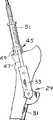
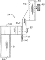
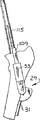
数多くのさまざまな器具が、ヘッド−ネック大腿人工骨1を移植するために有効であり、角度ガイドは、通常符号29で示し、図7Aないし7Cで図示するが、大腿骨Fに対して複数の切除処理、穿孔処理、および拡孔処理を施すための器具を所定位置に固定するための、大腿骨シャフトSに着脱可能に固定できるようになっている。角度ガイド29は、適当なクランプ(図示せず)により、大腿骨シャフトSと互いに向き合って係合し、着脱可能に固定されるようにした、第1部材31Aを含むブラケット31を有する。第2部材31Bは、第1部材31Aから外側方向に伸び、弓状面板31Cを有している。ガイドスリーブまたはアウトリガー(図9Aないし9E参照)の部分は、大腿骨シャフトの一方側でブラケット31から上方向に、そして外方向に所定の角度で伸ばすことができる。ガイドスリーブ33は、ねじ35でブラケット31に固定される取付部33Aを有している。ねじ35を緩めて、ねじ上にあるガイドスリーブを所定の角度位置まで回転させることにより、ガイドスリーブ33をブラケット部31に対して角度的に調整することができる。ガイドスリーブの角度を示すために、取付部33Aに付随する指針37により指し示される指標が、面板31Cに記されている。この角度は、ブラケットが大腿骨に固定された際の個々の患者の大腿骨に合わせて、先に決定した平均的な圧力負荷ベクトル(大腿骨Fが負荷を受ける「正常」な方向、AX−5)に実質的に平行な線に沿って、ガイドスリーブ33がブラケット31から伸びるように選択される。ガイドスリーブ33は、他の器具をガイドスリーブと同じ角度位置で受容して保持するための貫通孔39を有する。
上述したように、角度ガイド29は、本発明の人工骨1を移植するために用いられる、多様で異なる器具を保持するようにしたものである。そのような器具の1つには、鋸ガイド41(図4B参照)があって、これは、大腿骨ネック部を切除する鋸歯(図示せず)を案内するために、ガイドスリーブ33の貫通孔39内に着脱可能に取り付けることができる。鋸ガイド41は、ガイドスリーブ33の中央長手方向軸に通常垂直な鋸切断スロット41Aを有する。鋸ガイド41は、大腿骨ネック部Nに対して適当に配置するために、貫通孔39内を滑動可能に調整できる。鋸ガイド41を調整位置で固定するために、角度ガイド29に固定ねじ43が設けてある。
ここで図10Aないし10Dを参照すると、突起研削ガイドは、通常符号45で示すが、鋸ガイド41と同様の手法で角度ガイド上に取り付けるために、角度ガイド29の貫通孔39内に受容できるアウトリガー47を有する。突起研削ガイドは、アウトリガー47に固定されるガイドチューブ49を有する。突起研削ガイド45は、大腿骨ネック部Nの大腿骨ネック台座に対して適当に配置するために、ガイドスリーブ33に沿って貫通孔39内で滑動可能に調整できる。突起研削ガイド45は、ガイドスリーブ33に対して回転しないように固定して保持される。大腿骨ネック部Nに対する突起研削ガイドチューブ49の位置の方向は、AX−1軸と一致する。
大腿骨Fに形成される孔の側面を徐々に広げるために、連続的により大きくする直径を有する数多くの突起研削器(図示せず)が設けられる。最終的な突起研削器51(図11Aないし11C)は、人工骨1と内側骨内膜との間を密着させるために、内側骨内膜に第1孔B1の孔を穿つような大きさを有している。
挿管(カニューレ)されたピンガイド53(図12Aないし12D)は、突起研削ガイド45のガイドチューブ49を貫通して受容され、突起研削器51により大腿骨ネック部N内に形成された第1孔に滑動可能に受容されるような大きさを有している。挿管ピンガイド53は、トロカール指示ガイドピン57(図4N参照)およびドリル指示ガイドピン59(図4P参照)を滑動可能に受容するための中央軸通路55を有する。トロカール指示ガイドピン57およびドリル指示ガイドピン59は、例えば3.5mmの同じ径を有する。
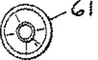
挿管皮質ドリル61(図13Aないし13D)は、ドリル指示ガイドピン59上に滑動可能に受容されるような大きさを有している。挿管皮質ドリル61は、人工骨1の股関節に近い部分のステムよりも径が僅かに小さい前方側部の大腿骨皮質部Cに貫通孔を穿つような大きさを有する(例えば9.5mmの人工骨ステム径に対して9mm)。
オフセット拡孔ガイドは、一般に符号63で示すが(図14Aないし14E)第1孔B1に滑動可能に受容されるような大きさを有する。オフセット拡孔ガイド63は、トラニオン65と、プラットフォーム69上に取り付けられたガイドフィンガ67と、末端部領域(股関節部から遠い部分の領域)71とを有している。オフセット拡孔ガイド63の末端部領域71は、第1孔B1を貫通する通路を許容するような大きさ(図示された実施例では14mm)を有し、第1孔を貫通しやすくするために弾丸形状末端部を有する。プラットフォーム69の外形形状(拡孔ガイド63の端部から分かるように)は、一般には、軸が平行な2つの半径方向に重なり合ったシリンダ(図14Cおよび14E参照)の重なり合わない表面形状である。拡孔ガイド63の末端部領域71の軸と同軸上にある重なり合うシリンダのうち、より大きい方のシリンダ69Aは、より小さい方のシリンダの69Bよりも大きい。より小さいシリンダ69Bは、より大きいシリンダ69Aとの公差点に向かって下方向に傾斜した平面で切断される。プラットフォーム69の最大の断面寸法は約15mmで、第1孔B1に関して、線と線で適合させることができる。ただし、プラットフォームの断面寸法は、骨の大きさに依存して変わることを理解する必要がある。
ガイドフィンガ67は、トラニオン65と平行して配置して、通常位置合わせをする。挿管拡孔器73(図15Aないし15D)が骨を切除する際、トラニオン65を所定位置に保持しやすくするために、ガイドフィンガ67を大腿骨F内の骨内膜の壁に接触させる。トラニオン65は円筒形状で、オフセット拡孔ガイド63の末端部領域71の中央長手方向軸とは約6mmずれている。ずれの精密な距離は、人工骨1が移植される骨の大きさに依存して変わる。大腿骨F内に形成される第1孔B1のAX−1軸と平行なラインに沿って拡孔器を案内している際、骨を拡孔するためにトラニオン上で挿管拡孔器が回転できるように、トラニオン65は、挿管拡孔器73を受容するような大きさを有している。挿管拡孔器73は、第2孔B2を形成する。
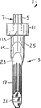
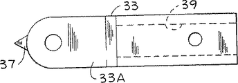
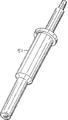
突起研磨ガイドは、一般に符号75で示すが、上側部分77Aおよび下側部分77Bを含むステム77と、ステムと通常同軸上にあるトラニオン79とを有している(図16Aないし16D参照)。突起研磨ガイド75は、第1孔B1を貫通しやすくするために、弾丸形状の遠位先端部を有している。ステム77の形状は通常、下側ステム部分77Bが滑らかである点を除いて(つまり人工骨1のスプライン19がない)、人工骨1の形状と同じである。ステムの上側部分77Aは、大腿骨ネック部に形成された2倍の骨(第1孔B1および第2孔B2)を有する構成に受容されている。突起研磨ガイド75は、研磨ガイドが大腿骨内で動かないよう固定するために、第1孔B1および第2孔B2内にすっぽりと係合する。図16Aおよび16Bで示す実施例において、ステム77の外側表面は滑らかである。
しかし、突起研磨ガイドは、人工骨1の形状によく似た形状に対応させることが好ましい。図16Dは、突起研磨ガイド75'の実施例を示すが、このときステム77'は、人工骨1のスプライン19と同一に対応するスプライン77C'を有する。人工骨1がステム13の上側部分15上にもスプラインを有している場合は、同様のスプライン(図示せず)を上側部分77A'上にも形成される。人工骨1と研磨ガイド75'のステム(13,77')の形状が精密に合致すればするほど、カラー部7の下側部分と、ネック部Nに形成される台座とをより精確に合致させることができる。
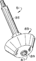
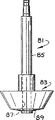
本発明の突起研磨器(一般に符号81で示すが)には、大腿骨Fの切除されたネック部Nの上に人工骨1のカラー部7の台座が形成される(図17Aないし17C参照)。突起研磨器81は、通常符号83で示すヘッドと、ヘッドから同軸方向に伸びるシャフト85とから構成される。突起研磨器は、トラニオン79上の研磨ガイドに対して回転できるよう研磨ガイド75上に研磨器を取り付けるための、研磨ガイド75のトラニオン79を受容する中央軸通路87を有する。へッド83の底面89は、円錐台形状を有している。研磨器81が研磨ガイド75上に取り付けられた際、中央長手軸AX−1に垂直な面に対する円錐台の傾斜角度は、約10゜である。ヘッド83の側面91は、やはり円錐形状であり、中央長手軸AX−1に垂直な面に対する傾斜角度は、約60゜である。ヘッド83の形状は、カラー部7の下側部分(9A,11A)にかなり一致している。
平坦な下側部分9A''を有する人工骨1''が移植される場合、ヘッド部83'の底面89'も同様に平坦である。平坦な底面を有する突起研磨器81'を図18Mで示す。平坦な底面の突起研磨器81'と人工骨1''とを用いると、人工骨と突起研磨器により形成されるネック部N上の台座との間が、極めて高い水準で一致する可能性が増大するだろうと考えられている。
(c)人工骨の移植方法
本発明の人工骨1の移植方法によれば、大腿骨Fに対する正常な負荷を反復性よく確実に与えることができる(つまり人工骨を移植する前の負荷)。本発明による1つの好適な方法を図4A、4B、4Mないし4Sで示す。あまり好適でない方法を図4Aないし4Lで示す。最も好適な方法を図18Aないし18Pで示す。正常に負荷された状態を反復性よく実現できない場合、ヘッド−ネック大腿人工骨により、大腿骨Fに伝わる応力の配分が変化する。ここに一体のものとして統合される米国特許第4,998,937号で説明したように、ウルフの法則によれば、応力配分に関するこれらの変化により、やがて骨の内部構造が変質する。以前よりも応力が少なくなった部位は、劣化しやすくなり、以前よりも応力が増えた部位は、厚みを増すことになる。正常な負荷された場合の応力よりも過剰に増加した応力を、長時間負荷し続けていると、骨細胞を死滅させてしまう可能性がある。正常な負荷を反復性よく与えるために、本発明による方法は、人工骨1のステム13を、人によって異なる平均的な圧力負荷ベクトルに一致するように配置する。
図1Aを参照すると、人間の大腿骨Fは、外見的に2つの軸を有する。つまり大腿骨ネック部の軸AX−4と大腿骨シャフト部AX−3である。しかし、骨は、外見的な2つの軸のいずれの軸にも沿わずに、応力負荷され、むしろ(平均的な圧力負荷ベクトルに平行な)第3の軸を通じて応力負荷され、この軸は一見しても明確でない。圧力負荷、および大腿骨Fが受ける応力エネルギ密度に呼応して、圧力骨梁と呼ばれる骨の強化ラインが大腿骨内部に形成される。これらの強化ラインの集まったところが圧力骨梁ストリームTSである。図1Aで示すように、大腿骨ネック部の圧力骨梁が集合したところを、中央骨梁ストリームTSと呼び、中央骨梁ストリームの平均的な方向を中央骨梁ストリーム軸AX−5と呼んでいる。軸AX−4が大腿骨シャフトの中央長手方向軸AX−3となす角度θは、通常140゜から170゜の範囲にある。実際には、この角度は、軸AX−5と大腿骨Fの側部表面との間の股関節部のX線形状から測定される(図4A参照)。人工骨1を配置するために、中央骨梁ストリームTSを用いることについては、米国特許第4,998,937号に教示されている。
本発明による方法を用いて大腿骨F内に人工骨1を移植するために、まず最初に、股関節部の結合部品と大腿骨の側部を露出させる。大腿骨ネック部の中央長手方向軸AX−2を通る垂直面P−1は、図1Bに示すように、大腿骨シャフトの中央長手方向軸AX−3を通る側部−中央部の平面P−2に対して、一般に、約15゜前方を向いている。この角度を一般に、大腿骨ネック部の「頚部前傾(アンテベルジオン)」と呼ぶ。したがって(ブラケットは軸AX−3の側部にあり、大腿骨ネック部は中央部にあるため)ブラケット31の垂直軸が、側部−中央部の平面P−2から約15゜後方にある平面P−1上にのるように、角度ガイド29を大腿骨F上の半径方向にずらした位置に配置する。このように配置すると、ガイドスリーブ33を通る垂直平面P−3は、平面P−1と平行となる。角度ガイド29は、大腿骨Fが股関節に対して隣接する近位−遠位方向に配置されるので、ガイドスリーブ33の上端部は、図1Bで示すように大腿骨ネック部の根元に対して中央に配置される。そして、角度ガイド29は、クランプを用いて(図示せず)大腿骨シャフト部S上に固定される。ブラケット31に対してねじ35を緩めることにより、ガイドスリーブ33が調整されるので、大腿骨シャフト部Sの中心軸AX−3に対する角度が、中央骨梁ストリームTSの角度θと一致する。これは、ガイドスリーブの指針37をブラケット31の面板31C上に表示される適当な角度に傾けることにより実現される。
ガイドスリーブ33上に鋸ガイド41を(股関節に対して隣接する近位−遠位方向に)配置して、鋸切断スロット41Aが大腿骨ネック部Nのベース部付近に配置され、通常図4Bで示すように、大腿骨Fの後方大腿骨皮質の上部表面に配列される。このように配列すると、鋸切断スロットは、中央骨梁ストリームTSに対して垂直となる。角度ガイド29のガイドスリーブ内に鋸ガイド41をしっかりと固定するために、固定ねじ43が締め付けられる。
大腿骨シャフトSの中央長手方向軸AX−3に対して約60゜の角度で後方大腿骨皮質から伸びる切除表面を形成するために、鋸ガイド41が所定位置にあるとき大腿骨ネック部Nは、振動鋸(図示せず)を用いて、鋸を鋸切断スロット41Aに通過させることにより切断される。その後、鋸ガイド41は、ガイドスリーブ33から取り外されて、角度ガイド29は、大腿骨シャフトSの当初の位置に固定したままにしておき、大腿骨ヘッド部が切除される。
股関節部全体を置換する必要がある場合(すなわち大腿骨ヘッド部および股臼の置換が必要な場合)、ここで股臼を用意しなければならない。
第1の好適な実施例によれば、図4A、4B、4Mないし4Sで示すように、突起研削ガイドがガイドスリーブ33に固定され、これにより、突起研削ガイドを大腿骨ネック部Nの切断表面に効率的に中央に配置する。角度ガイド29は、軸AX−5と平行な突起研削ガイドとも配列する。最初の孔が大腿骨ネック部Nに開けられる。
比較的に小さい研削直径を有する研削器(図示せず)は、大腿骨ネック部を研削するために、突起研削ガイド45内に滑動可能に受容される。大腿骨ネック部Nを、前の研削器よりも大きい径を有する研削器で連続的に端面および側面から切断研削し続ける。大腿骨ネック部Nは、骨内膜と呼ばれる内側ライン(または表面)を有する。最終的な研削径は、中央骨内膜に隣接する第1孔B1の適当な直径を与えるために、個々の大腿骨により決定される。適当な直径を有する突起研削器51は、中央骨内膜内に最終的な直径(例えば15mm)の孔を空ける。その後、突起研削器51は、突起研削ガイド45から取り外される(図4M参照)。
図4Nで示すように、挿管ピンガイド53が突起研削ガイド51内に、そして中央骨内膜の第1孔B1内に受容される。トロカール指示ガイドピン57が、後方骨内膜に開始印を記すために、挿管ピンガイド軸通路55に受容される。開始印が記された後、トロカール指示ガイドピン通路55から取り出される。穿孔指示ガイドピン59が挿管ピンガイド軸通路55に受容され、後方側の大腿骨皮質Cを貫通する孔を形成するために用いられ、これにより、後方側大腿骨皮質に斜め方向に孔が形成される。穿孔指示ガイドピン59は、皮質に斜めの孔を開けた後、所定位置にそのままにしておき、挿管ピンガイド53を大腿骨Fから取り出し、突起穿孔ガイド45を角度ガイド29のガイドスリーブ33から取り外す。
図4Pで示すように、挿管皮質ドリル61は、突起研削器51により研削された第1孔B1と同じ軸上で、後方側大腿骨皮質Cを貫通するように穿孔するために、穿孔指示ガイドピンの上に受容される。皮質ドリル61は、大腿骨Fに形成された第1孔B1よりも小さい径を有する斜め孔を穿つ。そして挿管皮質ドリル61、および穿孔指示ガイドピン59は、大腿骨Fから取り出される。
オフセット拡孔ガイド63が、ここでまず、第1孔B1弾丸端部内に配置される。最初の挿管拡孔器(図示せず)はトラニオン65上に受容されると、大腿骨ネック部N内を第1孔B1と平行な第2孔B2で孔を広げる。後に使う拡孔器がより大きい径を有するようにして、挿管拡孔器(図示せず)を連続的に使用する。最後の挿管拡孔器73は、人工骨1および骨内膜の間で線と線との接触が実現する径にまで第2孔B2を拡孔する(図4Q)。人工骨1の上部ステム部分15が納まるまで深く第2孔の孔が広げられると、挿管拡孔器73およびオフセット拡孔ガイド63は、大腿骨Fから取り出される。
図4Rを参照すると、突起研磨ガイドは、第1孔B1の近接側面内に、後方側皮質C内の斜め孔を貫通して挿入される。トラニオン79および突起研磨ガイド75のステムの中央長手方向軸が第1孔B1と同一直線上にある。そして突起研磨器81はトラニオン79上に配置され、大腿骨ネック部の表面は、人工骨1のカラー部9の台座を形成するために圧力が突起研磨器に負荷されたときでさえも、第1孔B1の軸(AX−1)と通常垂直な方向に配置される。大転子Tは、突起研磨器81により実質的に保護される。大転子Tの角度のある領域だけは切除されて、カラー部7のフランジ11のための傾斜した台座を設ける。こうして、大転子Tの大部分を犠牲にすることなく(図1)、人工骨1を上部大腿骨の皮質骨Cの上にしっかりと固定することができる。
突起研磨器81の底面89は、多少カップ形状になっているため、大腿骨ネック部N上の台座の部分が軸AX−1の下方向に傾斜している。この台座部分の形状は、人工骨のカラー部7の下側部分9Aの形状と相補的なものとなっている。大腿骨ネック部N上の台座がカップ形状であるため、人工骨1を配置しやすくなる。さらに、カラー部7の下側部分と台座の形状が一致するとき、台座の全体領域は、カラー部7の下側部分(9A,11A)と係合し、ここに人工骨1からの負荷が加わる。カラーの表面(9A,11A)と全体領域に亙って係合する台座を有する骨材料に応力負荷されると、人工骨1が移植された後、骨の吸収(退行)を阻止することができる。しかし巨視的に一致させることは重要である一方、生体作用の、あるいは化学的な被膜(例えばリン酸カルシウム化合物)に関連する微視的な粗さ、あるいはカラー下側部分(9A,11A)の多孔性により、骨が台座から内部成長させることができ、その結果、カラー表面と台座が結合しやすくなる。カラー下側部分(9A,11A)は、100%皮質接触しているため実質的に100%皮質による応力負荷させることができ、化学被膜は、カラー部7の下側部分の上だけに用いられ、ステム13上のその他の位置では用いられない。研磨後、突起研磨器81および突起研磨ガイド75は取り外される。
そして人工骨1は(ボール3を省く)、図4Sで示すようにステム13を第1孔B1に挿入することにより移植される。ステムのスプライン19は、第1孔B1の壁に食い込み、ステムは斜め孔を貫通して僅かに突出しているため、その後、皮質骨がステム末端部上方で成長することはない。応力負荷を股関節部から上部大腿骨へ伝える人工骨1の性能を阻害するので、ステム13の端部の上方に骨が成長することは好ましくない。上側ステム部分15は、第1孔B1内に密接に係合する。カラーのプラットフォーム9の下側部分9Aは、突起研磨器ヘッド83の底面89により形成される台座部分と合同の形状をしており、フランジ11の下側部分11Aは、突起研磨器ヘッドの側面91により形成される大転子T上の台座の部分と合同である。
一旦、人工骨1が移植されると、適当な大きなのボール3が、ネック部の上方で固定される。
第2のあまり好適でない実施例では、処理手順が若干変更される。図4Cおよび4Dを参照すると、大腿骨ネック部Nが切除された後、(突起研削ガイド45とよく似た構造の)拡孔ガイド95が角度ガイド29のガイドスリーブ33に固定され、これにより拡孔ガイドが大腿骨ネック部Nの上の中央に効率よく配置されることにより、第2孔が先に形成される。先と同様、第2孔は、先の拡孔器(図示せず)よりも大きい径を有する拡孔器を反復して使用することにより形成される。最後の拡孔器97の直径は21mmなので、大腿骨ネック部Nは21mmの径を有するまで拡孔される。その後拡孔ガイド95は、ガイドスリーブ33から取り出され角度ガイドは、固定されたまま放置される。
トラニオン101を有する突起研削ガイド99は、角度ガイド29に固定され、第1孔B1は、最後の突起研削器103を含む一連の突起研削器(図4Eおよび4F)を用いて研削することにより形成される。突起研削ガイド99をより明確に示すために、図4Fでは角度ガイド29が省略されている。突起研削ガイド99は、角度ガイド29から取り出され、ドリルピンガイド105が角度ガイド上に取り付けられる。図4期を参照すると、ドリルピンガイド105の上側部分は、第1孔B1および第2孔B2と適合させるために、人工骨のステム13の上側部分15とよく似た二重のシリンダ構成を有している。角度ガイド29は、図4Gでも図示していない。より好適な実施例における同じトロカールピン57およびドリルピン59は、大腿骨Fの後方中央部の皮質に末端孔を穿ち始めるために、あまり好適でない実施例のドリルピンガイド105とともに用いられる。研磨処理および研磨器具は、最初のより好適な実施例による方法で説明したのと同一のものである。
第3の、図18Aないし18Pで示す最も好適な実施例において、処理手順およびいくつかの器具が変更されている。中央骨梁ストリームTSの角度を決定する最初の処理手順(図18A)が、図4Aを参照しながら上述したそのままの通りに実施される。一旦、中央長手方向軸AX−3に対する中央骨梁ストリームの角度を決定すると、角度ガイド29のガイドスリーブ33の角度は、上述の通り固定される。最も好適な実施例では、一般に符号101で示す分度器を用いてこの角度を確認する。分度器には、角度ガイド29のブラケット31が配置される停止線がある。回転可能なアーム105は、固定ねじ107を緩めることにより、中央骨梁ストリームTSの角度に相当する角度まで移動させることができる。アーム105をねじ107により固定し、ガイドスリーブ33の面とアームの面がぴったりとくっつくようにする必要がある。そうでなければ、分度器101のアーム105の角度に合致するまで、スリーブガイド33を回転させる。分度器101のメモリがより細かければ、角度ガイド29をより精確に固定することができる。
図18Cで示すように、角度ガイド29は手術で露出させた大腿骨に固定し、鋸ガイド41は角度ガイド内に固定される。大腿骨ヘッド部を切除する手順は、図4Bを参照して上述したのと同じ手順である。鋸ガイド41は、角度ブラケットから取り外され、ガイドスリーブ33から通常上方向に、そして大腿骨の切除されたネック部を超えて伸びる視認調整バー109と置換される。図18Dおよび18Eで示すように、大腿骨に最初の孔HOを形成するために、視認調整バー109で示す角度に沿って、手術により拡孔器111を大腿骨内に案内する。こうして形成された孔HOは、バー109で示すように、中央骨梁ストリームTSに平行で、適当な頚部前傾角度を有する長手方向軸を有する。拡孔処理は、十分な径を有する孔を形成するために、拡孔器111、および徐々に径を大きくした拡孔器を数多く連続的に用いることにより実施される。熟練した外科医なら、あるいは拡孔器111だけを用いて、十分な径を有する孔HOを形成することができる。この場合、外科医は、十分な径となるまで拡孔器111を連続的により大きい円で動かす。孔HOの最終的な径は、個々の患者の大腿骨の大きさと形状により決定される。
人工骨を最適に係合させるために孔の採寸処理が、図18Fで示す寸法測定器のような大腿骨寸法測定器113を用いて実施される。寸法測定器113は、移植される人工骨1''のステム13''の上側部分15''形状と実質的に同一である。寸法測定器の大きさには色々ある。例えば、寸法測定器のより大きいシリンダ部分113Aは、18mmから26mmまで1mm間隔で大きさの異なるものがある。寸法測定器113は、視認調整バー109(図18Fでは示さず)に対して平行な孔HOの内部に挿入される。大腿骨に係合する最大の人工骨の大きさを決定するために、連続してより大きい寸法測定器を股関節に近い大腿骨内に適合させる。このとき外科医は、移植すべき人工骨1''の大きさ、および人工骨1を受容するために必要な径B1とB2の正確な寸法を知ることになる。人工骨1''は、孔HO内に適合できる最も大きい寸法測定器よりも大きい寸法を有するように選択される。例えば、適合する最も大きい寸法測定器が14.5mmよりも小さい径を有する場合、上側ステム部分の径が15mmより小さい人工骨が用いられる。
第1孔を形成するために、第1孔の最終的な径(例えば15mm)に対応する径を有する拡孔器115が選択され、第1孔を形成するために使用される。図18Gで示すように、拡孔器は視認調整バー109を用いてフリーハンドで案内される。少なくとも径の一部が中央大腿骨皮質の骨内膜で囲まれるように、第1孔B1が形成される。つまり、人工骨1''は、埋め込まれた際、径B1内のこの位置で堅い皮質骨に係合される。後方中央部の大腿骨皮質に、中央骨梁ストリームTSと正確に平行で、かつ適当な頚部前傾角度を有する孔を穿つために、一連の、異なる大きさを有する一体式の挿管されたアウトリガーピンガイド117(1つだけ図示する)が用いられる。新しく形成された径B1の直径に対応する形を有するピンガイド117が選択され、この径内に挿入される。ピンガイド117のアウトリガーは、ピンガイドを最も正確に配置するために径B1内に挿入されると同時に、角度ガイド29のガイドスリーブ33内に受容される。ガイドの傾斜した先端部は、後方側大腿骨皮質の骨内膜と接触するまで、第1孔B1内に挿入される。
ドリルガイドピン119は、ピンガイド117内に挿入される。ガイドピン119の大腿骨内における方向は、角度ガイド29が中央骨梁ストリームTSと平行で、かつ適当な頚部前傾角度であるような適当な角度のままであることを確認することによりチェックされる。さらにピンガイド117は、大腿骨ネック部皮質の骨内膜表面と接触していることを確認してチェックされる。ドリル(図示せず)は、ガイドピン119に固定され、後方大腿骨皮質を貫通して穿孔する。図18Iで示すように、ピンガイド117および角度ブラケット29は、大腿骨から取り出し、ガイドピン119はそのままにしておく。次の処理は、後方側大腿骨皮質を貫通する皮質間のトンネルを開けることである。人工骨1''の下側部分17''の直径に対応するように、挿管ドリル121が選択される。例えば、下側部分17''の直径が9.5mmであるとすると、9mmの挿管ドリルが選択される。図18Jで示すように、挿管ドリル121は、径B1の直径に対応する大きさを有するガイドフェルール123と共に挿入される。こうして図18Kで示すように、ガイドフェルール123により、径B1の長手方向軸とドリルを(ガイドピン119に沿って)配列しやすくなる。挿管ドリル121は、ドリルの上に受容されたガイドフェルール123を用いてガイドピン119上を滑動し、皮質間のトンネルが後方側の大腿骨皮質に形成される。穿孔処理中は、フェルール123が中央骨内膜皮質に接していることを確認するように注意しなければならない。
図18Lで示すように、図4Qに関連して上述したのと同一の処理手順で、第2孔B2が形成される。ただし、図18Lで示すように、オフセット拡孔ガイド63'は、大腿骨内に拡孔ガイドをより正確に方向付けるためのスプライン71A'を有する。
図18Mで示すように、径B1およびB2に挿入される突起研磨ガイド75'は、人工骨1''の形状と最終的に同一になる。研磨ガイド75'は、下側ステム部分77B'上に、人工骨と同じようなスプライン77C'を有する。突起研磨器81'は、研磨ガイド75'のトラニオン79'上に受容され、平坦な台座が大腿骨ネック部N上に形成される。研磨器が台座を形成するために回転するときに、ぐらつかないようにするために、トラニオン79'と研磨器81'との間の遊び(トレランス)が殆どないようにしておくことが望ましい。
図18Nを参照すると、人工骨1''は、人工骨の端部に固定されたガイド先端部125を用いて大腿骨内に挿入される。とりわけ、ガイド先端部125は、人工骨1''の末端部内の孔(図示せず)に受容されるステム(図示せず)を有する。先端部125は、孔の内部に摩擦係合している。先端部125が弾丸端形状であると、先端部が後方側大腿骨皮質を貫通する前に、人工骨が骨上で動きが取れなくなるのを防ぐのに役立つ。一旦移植されると、図18Pのように、先端部125は人工骨1''から引き抜かれる。人工骨1''は、カラー部7''が大腿骨ネック部Nの台座の上に完全に納まっていること、およびステムの大腿骨からの飛び出し具合が適当であることを確認してチェックされる。
図19Aないし19Dが図示するのは、さらに別の実施例における人工骨1'''のカラー部7'''が大腿骨ネック部Nに対して完全に納まっていることを絶対的に確かめるために実施できる追加的処理である。人工骨1'''が人工骨1''と異なるところは、フランジ11'''の下側部11A'''が2つの交差する平面を有するところだけである。人工骨のフランジ11''の下側部11A''は、円錐領域の形状を有する。鋸テンプレートは、通常符号127で示すが、人工骨1'''のネック部5'''上に適合し得るキャップ128を有する。このキャップ128により、カラー部7'''のちょうど下方に、そしてフランジ11'''の中央側にスロットを正確に配置される。
そして鋸(例えば、振動鋸SW)が、カラー部7'''の下方にの大腿骨ネック部Nの余分な部分を切除するために用いられる。カラー部7'''の下側部(9A''',11A''')の形状とうまく一致するように切断するために、鋸テンプレート127により鋸SWおよび往復運動式鋸(図示せず)がガイドされる。下側部11A'''の研磨器形状により、切断表面とフランジの下側部とを精度よく一致させながら、(例えば、図19Dの往復運動式鋸の刃B'などにより)フランジ付近で直線的に切断することができる。これらの部分を切除した後、カラー部7'''の下側部に残存する削りくずを洗い流し、完全に洗浄されたことを確認する。そしてネック部Nに対してうまく納まるように、この部分が取り除かれた後、人工骨1'''は、下方向に(例えば1ないし2mm)挿入される。
スロット129が鋸テンプレート127のリム131内に配置される。図19Dを参照すると、リム131は、人工骨1'''のステム13'''の上側部分15'''からの距離がどこでも一定であるような周辺端133を有する。周辺端133は、鋸刃が内側に移動するのを規制するために、固定ボルトSBにより鋸SWの刃の上で固定されている。つまりリム131形状により、確実に、鋸SWの刃Bがステム13'''の上側部分15'''に接触しないようにすることができる。
鋸テンプレート127が、研磨ガイド(75、75')および(81,81')突起研磨器と置換して用いられることは、明白である。人工骨1'''を移植するためのその他の処理は、上述の、あまり好適でない方法、より好適な方法、そして最も好適な方法に関して示したのと同一の処理である。しかし、カラー部7'''のための台座を形成するために大腿骨ヘッド部Hが切除された後、ネック部Nを研磨する必要はない。カラー部7'''の下側部(9A''',11A''')がネック部に係合するまで、人工骨1'''は、大腿骨F内に挿入される。鋸テンプレート126が人工骨1'''に固定され、カラーのための台座を形成するためにカラー部7'''の下方が切除される。鋸テンプレート127は、過去に移植された人工骨1'''を取り出す際にも便利に用いることができる。人工骨1'''に対する骨の内部成長は、(上述したように)カラー部7'''の下側部(9A''',11A''')上でのみ促進される。大腿骨Fからカラー部7'''の下側部(9A''',11A''')を分離するために鋸テンプレート127を用いて最低量の骨が切除される。
(d)本発明に関する研究
全股関節部の関節形成術(THA)において、人工骨周囲の骨が失われる原因となる大腿骨付近の応力のレベルが、髄内ステム大腿骨部品により減少する。この研究は、本発明による大腿骨ステム設計の応力パターンを、正常な大腿骨と、従来式のヘッド−ネック大腿人工骨とを比較して評価する。
曲がり難さを抑えた髄内ステムにより、THAで応力不足により骨が失われないようにする試みは、これまで成功しなかった(1)。移植された大腿人工骨に関する臨床研究によると、股関節部の負荷が伝わる軌跡は、比較的に狭い角度範囲に限定されることが分かった(2)。股関節部に近接する大腿骨の負荷を改善するための択一的なアプローチとして、それぞれの股関節部の平均的な合力負荷ベクトルと平行に大腿骨ステムを配置することができる。理論的には、安定したインターフェイス部を介して大腿骨ネック部に自然な負荷を加えると、正常な大腿骨に対する歪みと同等の歪みが生じることになる。カラー−ネック間の制限のない負荷を実現するためには、移植ステムが合成ベクトルのライン上の骨を貫通することが必要となる。この研究の目的は、骨移植THAによる人工骨に関する応力配分を決定することにある。
12からなる人工の大腿骨部に、12からなる3軸ロゼット応力ゲージ(例えば、図1の応力ゲージ109)が備えられており、そのうちの5つの応力ゲージは各々、後方−中央部から前方−側部に沿って伸び、1つの応力ゲージは股関節に近い前方から股関節に近い後方に伸びている。大腿骨は1つの肢場ジグ内に取り付けられている。712および1423ニュートンの人工骨の外転筋力を与えて、脊髄に1068および2135ニュートンの負荷を加え、大腿骨シャフト軸から21゜の外転を形成する。応力データは、微小応力に対する計測値に変換するコンピュータ化されたマルチチャンネルシステムを用いて収集される。
本発明の原理に基づいて構成されたプロトタイプのコバルト−クロム合金性の骨移植の大腿骨ステムは、処理しない大腿骨と同じ条件下で移植され負荷された。股関節に近いカラーは、10゜の円錐形状を有し、ステムに対して垂直であった。股関節に近いステムは、2つのシリンダ要素23および15の25からなり、各々21mmの直径を有し、骨内膜皮質と接線方向に接触した。縦スプラインを有し、直径が12mmの末端ステムが後方中央部にある11.5mm孔に貫通して圧入された。スロットのある(n=11)、およびスロットのない中身のある(n=12)2つの末端ステムの変更物が大腿骨で各々試験された。それぞれの大腿骨のX線写真が撮像された。側部シャフト皮質に対する移植角度は、146゜から158゜まで変化する。
8つの接着剤を用いないコバルト−クロム髄内ステム、およびおよび接着剤を用いる髄内ステム(インディアナ州ワールソウにあるデピュイ社が製造するレプリカ16.5−LG、およびレスポンス13.5)が移植され、検証された。
すべてのデータが、多様性に関して分析された。
2つの負荷状態に関して、対照的な応力パターンが確認された。次の結果は、より大きい負荷を与えた場合の結果である。この結果をグラフに表したのが図20である。
接着剤を用いない髄内ステム、および接着剤を用いる髄内ステムは、股関節部に近い後方中央部の圧力応力レベルは、正常な状態に比して、42.7±4.6%(平均±標準偏差、p=0.0007)および32.3±2.6%であった。
スロットのある、および中身の詰まった骨移植ステムは、股関節部に近い後方中央部の圧力応力のレベルは、119.0±7.4%(p=0.36)および101.1±16.6%(p=0.66)であった。圧力、張力、剪断力による応力レベルは、通常、処理しないレベルと比して、大幅に変わることはない。例外として、スロットのあるステムに関する最も大腿骨に近接する後方中央部のゲージでの張力応力が128.9±2.7%(p=0.029)であった。張力応力が相当増加したのは、スロットのあるステムおよび中身の詰まったステムに関するステム出口部に最も近いところであった(146.1±11.2%、p=0.0096、および188.6±11.9%(p=0.0006)。近接する応力レベルが高いと、移植の水平角度が大きくなるが、このことは直線回帰分析にはさほど重要ではない。
髄内ステムの大腿骨部品に関して減少する応力レベルにより、これまで報告されてきたものと同じであった(3)。髄内ステムの「係数不均衡」を解消するために相当な努力が払われたけれども、この研究が示唆したのは、軌跡の不均衡の方が、応力を取り除く上でより重要である可能性があるということだった。股関節の圧力骨梁は、大腿骨シャフトの軸に対して10゜ないし40゜横方向に傾いているということが分かった(4)。髄内ステムの上に結果的に生じる折り曲げモーメントにより、股関節部に近接するインターフェイス部に対する負荷を阻害しない。股関節部の負荷軌跡は、折り曲げモーメントを形成する髄内ステムの挿入軌跡(大腿骨シャフト軸)よりも水平方向に傾いている。
大腿骨部品(負荷ベクトルに配列されたステム)と一致させた軌跡により、折り曲げモーメントが小さくなり、負荷が軸方向に伝わりやすくなる。この骨移植設計に関して、円筒状の器具および対応ステムにより、股関節部に近い部分と遠い部分との間の皮質接触/巨視的内部固定に対して、回転したりぐらついたりしないように、しかもカラーおよびネック部とのインターフェイス部の圧力をうまく処理するように試みられた。股関節部に近い大腿骨の応力レベルは、このプロトタイプにより回復されたが、股関節に遠いステム付近の応力レベルがより高いために、大腿骨に痛みが生じる懸念が生じる。
人工の大腿骨の応力モデルによると、骨移植THAでの大腿骨部品により、髄内ステムよりも股関節部に近い大腿骨の応力レベルの方が高いことが証明された。
参考文献
(1)ボビン、J.D.他:CORR262:196,1990
(2)デイビィ、D.T.他:JBJS70A:45,1988
(3)オー、I、およびハリス、W.H.:JBJS60A:75,1978
(4)クラーク、J.M.他:J Arhr2:99,1987
上述を鑑みると、本発明のいくつかの目的が実現され、他の好適な結果が得られることが分かる。
本発明の範疇から逸脱することなく、上述の構成に多様な変化を加えることができ、添加図面を参照してなされた上述の説明および開示に含まれるすべての事項は、説明するためだけのものであって、限定的な意味に解釈すべきではない。This application is a continuation-in-part of US patent application Ser. No. 60 / 023,398, which is hereby incorporated by reference.
Background of the Invention
The present invention generally relates to head-neck femoral prostheses and methods for implanting the same.
Replacing the entire hip joint became the first practical clinical method in November 1963 due to the "adhesive fixing technology" of the component parts. The head and neck of the femur are resected, the upper medullary canal of the femur is cleaned (ie, the inside of the bone marrow is removed), and an acrylic adhesive is injected into the medullary canal of the femur, Of the femoral component is inserted into the liquid adhesive. After 10 to 15 minutes, the acrylic (methylmetacrylate) adhesive cures and the femoral stem is fixed. The acrylic adhesive is the same as the acrylic resin used when making a denture in dentistry. Adhesive fixation techniques for femoral components are still commonplace as a means of fixing implanted bone.
Glue fixation is a radical treatment that joins by forming and implanting bone. The liquid adhesive covers the entire internal surface of the upper femur. This type of fixation method is generally effective for a short period of time (10 years), but over a long period of time, it can cause bone distortion and loosening between the adhesive and the femoral component. Due to the adhesive and the implant that splints the upper femur, bone is lost and the natural bending of the upper femur is impaired. This is particularly problematic when the patient is young (ie, under 50).
Attempts have been made to perform essentially the same procedure as adhesive-based implants without glue or with "press-fit" femoral components. That is, an attempt was made to strongly fix the gap between the implant and the bone by maximally filling the medullary canal with the metallic implant. In other words, according to this concept, better fixation is achieved and more effective results are obtained if the metallic implant fills the medullary canal more closely. However, experimental results do not always work that way.
Glueless femoral stems are larger and thicker than their equivalent counterparts because they replace the more flexible layer of acrylic adhesive with metal. Glueless stems are made of the same material and have a larger diameter than glueless stems, making them more difficult to bend. If it is difficult to bend, the upper femur will not be able to well lie (splint) properly against the normal bending that occurs when walking (causing distortion). Although glueless intramedullary femoral stems provide acceptable clinical results, strain-deficient or less accurate, commonly referred to as `` strain shields, '' can result in the use of glueless stems. The rate at which the upper femur is lost is faster.
In short, the conventional method of fixing the entire hip joint in the intramedullary region with the femoral component most largely depends on whether the upper femur and the medullary canal are filled with an adhesive and metal, or only metal. Although not simultaneous, bone loss occurs for all these implants.
Summary of the Invention
Some objects and features of the present invention are to provide a head-neck femoral prosthesis that protects the femur from bone loss, a prosthesis having a stable pedestal between the prosthesis and the femoral neck. Providing bone, providing an artificial bone that receives pressure at the interface of the upper femur, providing an artificial bone that suppresses the splint of the upper femur, below the pedestal, the artificial bone is completely It is to provide an artificial bone that does not become immobilized, to provide an artificial bone that receives the load from the hip joint almost completely as pressure, and to provide an artificial bone having a longer useful life.
It is a further object and feature of the present invention to provide a method of implanting a head-neck femoral prosthesis that takes into account the historical loading of the femur, wherein the load applied to the prosthesis is substantially reduced to the femur. To provide a stable interface between the prosthetic collar and the femoral neck to transfer the load to the neck and upper femur to provide a natural and natural way of transmitting the load To provide an implanting method that does not completely fix the artificial bone in the axial direction; and to provide an implanting method that substantially reduces the bending moment applied to the artificial bone when implanted. And to provide a method of implantation which allows the artificial bone to be almost completely loaded as pressure.
Generally, the artificial bone to be implanted into the bone at the joint includes a neck portion for receiving the ball portion, a collar portion for attaching the neck portion, and a stem extending from the collar portion to the opposite side to the neck portion, Is provided. The artificial bone has a longitudinal axis corresponding to the longitudinal axis of the stem. When implanted in the bone, the stem is fixed so that it does not move about the longitudinal axis and does not move about an axis perpendicular to the longitudinal axis, and moves along the longitudinal direction. It is configured and arranged to prohibit being fixed so as not to be. The stem is secured so that it does not move about the longitudinal axis and does not move about an axis perpendicular to the longitudinal axis when implanted in the bone, and along the longitudinal direction. A longitudinally extending spline formed on the surface of the stem so as to prevent it from being fixed. Alternatively, the collar portion is configured to engage the bone to transfer a load to the bone, the collar portion having a first portion and a second portion, wherein the collar portion is capable of engaging the bone. The lower part of the two parts is oriented at an angle with respect to the lower part of the first part.
The artificial bone to be implanted into the bone at the joint includes a neck portion for receiving the ball portion, a collar portion for attaching the neck portion, and a stem portion extending from the collar portion to the side opposite to the neck portion. , Is provided. The artificial bone has a longitudinal axis corresponding to the longitudinal axis of the stem. The stem has an outwardly facing fixation surface for fixing the artificial bone to the bone. This secures the stem so that it does not move about the longitudinal axis and does not move about an axis perpendicular to the longitudinal axis when implanted in the bone, Prohibit being fixed so that it does not move along. This fixation surface is then generally parallel to the longitudinal axis of the artificial bone.
Another aspect of the invention is a method of implanting an adhesive-free head-neck prosthesis into a femur, wherein the femur includes a shaft portion and a neck at the upper end of the shaft on the medial side of the femur. And a part. Generally, the method includes determining the axis of the mid-trabecular stream of the femur and resecting the femoral neck to form a pedestal for the femoral neck. A first hole extending downward from the neck toward the posterior side of the femur is drilled through the femoral shaft along a line substantially parallel to the axis of the central trabecular stream. A second hole extending downwardly from the neck toward the posterior side of the femur along a line substantially parallel to the axis of the central trabecular stream, but spaced apart from the first hole, Ryton, Drill through the femoral shaft. The stem of the artificial bone is inserted into one of a first hole and a second hole extending through the shaft portion and extending to the side of the femur, and a part of the stem is formed into one of the first hole and the second hole. Accepted by.
The basic aspect of this device is the stem implanted in a line that matches the normal load trajectory of the individual hips as disclosed in my earlier US Pat. No. 4,998,937. When the stem is implanted in this direction, the main force on the implant is directed toward the tip (ie, as pressure). In other words, for each step taken, a person weighing 150 pounds will have 500 pounds of force on the hip joint when walking normally, and will be transmitted along the axis of the implant. The ultimate goal is for the femoral neck to absorb 100% of the load (joint response) through the collar. The force on the implant ball is applied to the collar against the resected neck. The ultimate goal is for the collar to transfer all the load to the femoral neck so that the bone experiences 100% normal distortion (bend).
It is also important that the interface between the collar and the bone be stable, since very strong loads are transmitted through the collar. In my earlier patented (stem / barrel / plate) design, the barrel / side plate components stabilize the stem and collar. The barrel keeps the stem from wobbling (the force to move the ball back and forth laterally) and from rotating. The collar / stem component has little or no impediment to axial rotation of the barrel with respect to the femur, so that dynamic pressure is freely applied to the femoral neck.
In my new invention, the upper femur can be replaced with a barrel / side plate to prevent wobble and rotation of the implant. Because the implant is configured to fit the mechanized upper femur, wobble and rotation are restricted, but pressure is tolerated. The stem near the thick hip is brought into contact with the inside of the femoral neck to prevent wobble and rotation. After excision of the femoral neck and removal of the bone marrow content, when viewed along the loading axis, a cavity can be identified in the femur that typically has an elliptical cross-sectional shape. This elliptical cross-sectional shape is substantially filled with two overlapping circles, one smaller than the other. The overlapping circles extend in three dimensions along the load axis, resulting in two overlapping cylinders. My new femoral prosthesis has a double cylinder shape. The upper femoral cavity is machined to allow this double cylinder shape to engage the upper femur.
The medial shape of the upper femur varies from person to person. The ultimate goal is to ensure that the surface of the dual cylinder shaped upper stem of the artificial bone contacts the femur at at least one point at all locations along the length of the upper stem. Due to the irregular shape of the bone, it is not possible to expand the hole cylindrically, parallel to one axis (ie the loading axis), so that the implant and the bone come into complete contact along the upper stem I can't. The straight side of the implant will contact the curved surface of the upper femur only in a few discrete areas. It is considered that this tangential contact is sufficiently possible to restrict wobble and rotation and to allow compression.
The mechanical processing of the upper femur basically consists of four processes: resection, perforation, perforation, and circular polishing.
Procedure 1: The mid-femoral neck cavity is dilated on a first axis that engages the smaller of the two cylinders.
Process 2: A hole is made in the femur on the same first axis.
Process 3: A hole is expanded (expanded) on a second axis parallel to the first axis such that the cavity of the side femoral neck engages the larger of the two circular cross-sectional shapes. .
Process 4: The neck is "polished" to match the collar shape.
The implant is then inserted into the femur so that it has a portion that is received in both circular cross sections.
Other objects and features according to the present invention will in part be obvious and will in part be set forth hereinafter.
[Brief description of the drawings]
FIG. 1 is a cross-sectional view of a head-neck femoral prosthesis according to the present invention implanted in the femur (the prosthesis is shown in solid lines).
FIG. 1A shows an untreated femur showing the mid-trabecular stream of the femur and the axes of the femur and the prosthesis.
FIG. 1B is a cross-sectional view showing a cross section of the femur, taken along a femoral neck.
FIGS. 2A to 2D are diagrams showing contact regions between the upper artificial bone and the bone at the positions indicated by 2A-2A to 2D-2D in FIG. 1, respectively.
FIG. 3 is a cross-sectional view of the lower stem taken along the line 3-3 of FIG. 1 at the splined portion of the lower stem.
4A to 4R are schematic diagrams of less preferred and preferred embodiments of a method for implanting an artificial bone.
FIG. 4A is a view of the femur showing the axis of the central trabecular stream.
FIG. 4B shows an angle guide and a cutting guide around the femur for resecting the femoral neck.
FIG. 4C is a diagram illustrating an angle guide, a dilation guide, and a dilator for expanding the femoral neck into a hole having a second hole.
FIG. 4D is a view showing a dilator for expanding a second hole of the femoral neck.
FIG. 4E is a diagram showing an angle guide, a projection grinding guide, and a projection grinder for grinding a first hole of a femoral neck.
FIG. 4F shows the protrusion grinding guide and the protrusion grinder for grinding the first hole in the femoral neck, omitting the angle guide for clarity.
FIG. 4G shows a drill pin guide, a trocar indicating guide pin, and a drill indicating guide pin for drilling through the lateral femoral cortex.
FIG. 4H shows a drill indicating guide pin and an intubated (cannulated) cortical drill for drilling through the lateral femoral cortex.
FIG. 4I is a diagram showing a state in which the protrusion polishing guide has been inserted into the femoral neck.
FIG. 4J is a view in which the protrusion polishing guide of FIG. 4I is omitted.
FIG. 4K is a diagram showing a protrusion polishing guide and a protrusion grinder for polishing a femoral neck.
FIG. 4K is a diagram showing a state of implanting an artificial bone.
FIG. 4M shows a first stage of a more preferred implantation process and a projection grinder for grinding the first hole.
FIG. 4N is a view showing an angle guide, a protrusion grinding guide, an intubation pin guide, a trocar indicating guide pin, and a drill indicating guide pin for piercing through the femoral cortex at the posterior central portion.
FIG. 4P shows a drill indicating guide pin and an intubation cortical drill for drilling through the posterior central femoral cortex.
FIG. 4Q shows an offset dilation guide and an intubation dilator for expanding the femoral neck into a second hole.
FIG. 4R is a diagram showing a protrusion polishing guide and a protrusion grinder for polishing a femoral neck.
FIG. 4S is a diagram showing an implanted artificial bone.
FIG. 5A is a perspective view of the split stem artificial bone of FIG.
FIG. 5B is a front view thereof.
FIG. 5C is a side view of the left side.
FIG. 5D is a side view of the right side.
FIG. 5E is a plan view thereof.
FIG. 5F is a bottom view of the split stem artificial bone.
FIG. 5G is a cross-sectional view of the split stem prosthesis according to the plane of
FIG. 5H is an enlarged bottom view of the split stem artificial bone showing splines on the stem.
FIG. 6 is a perspective view of a solid stem artificial bone.
FIG. 7A is a perspective view of the angle guide.
FIG. 7B is a side view of the left side.
FIG. 7C is a plan view thereof.
FIG. 8A is a perspective view of an angle guide bracket.
FIG. 8B is a front view thereof.
FIG. 8C is a plan view thereof.
FIG. 8D is a side view of the left side.
FIG. 9A is a perspective view of the arm of the angle guide.
FIG. 9B is a front view thereof.
FIG. 9C is an enlarged sectional side view of the left side of the arm.
FIG. 9D is a plan view of the arm of the angle guide.
FIG. 9E is a side view of the left side.
FIG. 10A is a perspective view of a projection grinding guide.
FIG. 10B is a front view thereof.
FIG. 10C is a side view thereof.
FIG. 11A is a perspective view of the projection grinder.
FIG. 11B is a front view of the projection grinder.
FIG. 11C is a bottom view of the projection grinder.
FIG. 12A is a front view of the intubation pin guide.
FIG. 12B is a perspective view of the intubation pin guide.
FIG. 12C is a bottom view thereof.
FIG. 12D is a sectional front view showing the bottom end of the intubation pin guide.
FIG. 13A is a perspective view of an intubation cortical drill.
FIG. 13B is a front view of the intubation cortical drill.
FIG. 13C is a bottom view of the intubation cortical drill.
FIG. 13D is a sectional front view showing the upper end portion of the intubation cortical drill.
FIG. 14A is a perspective view of an offset hole expanding guide.
FIG. 14B is a front view of the offset hole expanding guide.
FIG. 14C is a side view of the left side.
FIG. 14D is a plan view of the offset hole expanding guide.
FIG. 14E is a bottom view of the offset hole expanding guide.
FIG. 15A is a perspective view of the intubation dilator.
FIG. 15B is a front view of the intubation dilator.
FIG. 15C is a bottom view of the intubation dilator.
FIG. 15D is an enlarged sectional front view showing the upper end portion of the intubation dilator.
FIG. 16A is a perspective view of the protrusion polishing guide.
FIG. 16B is a side view of the left side.
FIG. 16C is a plan view of the protrusion polishing guide.
FIG. 16D is a front view of the protrusion polishing guide according to the second embodiment.
FIG. 17A is a perspective view thereof.
FIG. 17B is a front view of the protrusion polishing machine.
FIG. 17C is a bottom view thereof.
18A to 18Q show a method for implanting an artificial bone according to the most preferred embodiment.
FIG. 18A is a view of the femur showing the axis of the central trabecular stream.
FIG. 18B shows how the angle guide is adjusted before being attached to the femur.
FIG. 18C illustrates an angle guide and a saw guide around the femur for resecting the femoral neck.
FIG. 18D is a diagram showing an initial hole expanding step.
FIG. 18E is a vertical sectional view of FIG. 18D when the angle guide is omitted.
FIG. 18F is a diagram showing a state where dimensions of the artificial bone are measured in order to select an appropriate artificial bone.
FIG. 18G is a diagram showing a point grinder for grinding the first hole.
FIG. 18H is a diagram showing a pin guide and a drill instruction guide pin used when piercing through the femoral cortex at the posterior center.
FIG. 18I is a diagram showing the drill instruction guide pin after removing the pin guide.
FIG. 18J shows a cortical drill and sleeve used to pierce the femoral cortex.
FIG. 18K shows a cortical drill when received on a guide pin after drilling through the posterior central femoral cortex.
FIG. 18L is a view showing an offset hole expanding guide and an intubation hole expander for expanding a second hole in a femoral neck.
FIG. 18M is a diagram showing a projection polishing guide and a projection polishing machine for polishing the femoral neck.
FIG. 18N is a diagram showing a state in which an artificial bone having a detachable bullet tip is implanted.
FIG. 18P is a diagram showing an implanted artificial bone.
FIG. 19A is a diagram showing an artificial bone and a saw template attached to the artificial bone, which is used when fitting the artificial bone.
FIG. 19B is a cross-sectional view of the upper partial region of the femur and the saw template shown in FIG. 19A, typically at the center of the femur.
FIG. 19C is a plan view of the femur and the saw template.
FIG. 19D is a sectional view taken along a plane including line 19D-19D in FIG. 19A.
FIG. 20 is a graph showing a test result of the artificial bone according to the present invention.
Detailed Description of the Preferred Embodiment
(A) Head-neck femoral artificial bone
With particular reference to the drawings of FIGS. 1, 1A and 1B, an adhesive-free head-neck femoral prosthesis for bone implantation according to the present invention (generally designated 1) has been implanted into a femur F. The situation is shown. The femur is composed of a femoral shaft portion S, a femoral head portion H, a femoral neck portion N, and a trochanter T at the upper end of the femoral shaft on the side of the femur. The femur F has cortical bone C near the surface of the bone and relatively soft reticular bone and endosteum (not shown) inside the femur.
The
The
In a preferred embodiment, when the
The stem attached to the lower portion of the
An artificial bone 1 'according to a more preferred embodiment is shown in Fig. 6, which has a solid lower stem portion 17'. It is thought that the use of a solid (non-hollow) stem enables more accurate implantation and avoids axial fixation that can occur due to bone ingrowth into the
The distal end of the
The
As shown in FIGS. 2A-2D, the
However, because of the contact in discrete areas, the
(B) Instruments used to implant artificial bone
A number of different instruments are useful for implanting the head-neck
As mentioned above, the
Referring now to FIGS. 10A through 10D, the projection grinding guide, generally designated by the
In order to gradually widen the side of the hole formed in the femur F, a number of projection grinders (not shown) with continuously increasing diameter are provided. The final projection grinder 51 (FIGS. 11A to 11C) is sized so as to make a hole of the first hole B1 in the inner endosteal bone in order to make a close contact between the
The intubated (cannulated) pin guide 53 (FIGS. 12A to 12D) is received through the
Intubation cortical drill 61 (FIGS. 13A-13D) is sized to be slidably received on drill indicating
The offset aperture guide, generally designated 63 (FIGS. 14A-14E), is sized to be slidably received in the first aperture B1. The offset widening
The
The projection polishing guide, generally designated by the
However, it is preferable that the protrusion polishing guide be adapted to a shape very similar to the shape of the
In the projection grinder (generally indicated by reference numeral 81) of the present invention, a pedestal of the
If an artificial bone 1 '' having a flat
(C) Method for transplanting artificial bone
According to the method for transplanting the
Referring to FIG. 1A, a human femur F has two axes in appearance. That is, the axis AX-4 of the femoral neck portion and the femoral shaft portion AX-3. However, the bone is stressed rather than along any of the two apparent axes, but rather through a third axis (parallel to the average pressure loading vector), which appears to be It is not clear even if. In response to the pressure load and the stress energy density experienced by the femur F, a bone reinforcement line called a pressure trabecula is formed within the femur. The point where these reinforcement lines are gathered is the pressure trabecular stream TS. As shown in FIG. 1A, the place where the pressure trabeculae of the femoral neck gather is called a central trabecular stream TS, and the average direction of the central trabecular stream is called a central trabecular stream axis AX-5. I have. The angle θ formed by the axis AX-4 with the central longitudinal axis AX-3 of the femoral shaft is typically in the range of 140 ° to 170 °. In practice, this angle is measured from the X-ray shape of the hip joint between the axis AX-5 and the side surface of the femur F (see FIG. 4A). The use of the central trabecular stream TS to place the
In order to implant the
With the
When the
If it is necessary to replace the entire hip (i.e., if the replacement of the femoral head and the acetabulum is required), then the acetabulum must be prepared.
According to a first preferred embodiment, as shown in FIGS. 4A, 4B, 4M to 4S, the projection grinding guide is fixed to the
A grinder (not shown) having a relatively small grinding diameter is slidably received within the
As shown in FIG. 4N, an
As shown in FIG. 4P, the intubation
An offset widening
Referring to FIG. 4R, the protrusion polishing guide is inserted through the oblique hole in the posterior cortex C into the side surface adjacent to the first hole B1. The central longitudinal axis of the stem of the
Since the
Then, the artificial bone 1 (omitting the ball 3) is implanted by inserting the
Once the
In a second, less preferred embodiment, the procedure is slightly modified. Referring to FIGS. 4C and 4D, after the femoral neck N has been resected, a perforation guide 95 (similar in construction to the protrusion grinding guide 45) is secured to the
A
In the third, most preferred embodiment shown in FIGS. 18A-18P, the procedure and some instruments have been modified. The first procedure for determining the angle of the central trabecular stream TS (FIG. 18A) is performed exactly as described above with reference to FIG. 4A. Once the angle of the central trabecular stream with respect to the central longitudinal axis AX-3 is determined, the angle of the
As shown in FIG. 18C, the
The hole dimensioning process is performed using a femur
To form the first hole, a
The
As shown in FIG. 18L, the second hole B2 is formed by the same processing procedure as described above with reference to FIG. 4Q. However, as shown in FIG. 18L, the offset drilling guide 63 'has a spline 71A' in the femur for more accurately orienting the drilling guide.
As shown in FIG. 18M, the
Referring to FIG. 18N, the
FIGS. 19A-19D illustrate the absoluteness of the collar 7 '''of the prosthetic bone 1''' in yet another embodiment to ensure that it is fully seated relative to the femoral neck N. This is an additional process that can be performed. The only difference between the
A saw (eg, a oscillating saw SW) is used to cut off the excess portion of the femoral neck N below the collar 7 '''. Saw SW and reciprocating saw (not shown) by
A
Obviously, the
(D) Research on the present invention
In total hip arthroplasty (THA), the level of stress near the femur that causes bone loss around the prosthesis is reduced by the intramedullary stem femoral component. This study evaluates the stress pattern of a femoral stem design according to the present invention comparing a normal femur with a conventional head-neck femoral prosthesis.
Attempts to prevent bone loss due to insufficient stress in THA with an intramedullary stem with reduced bending have been unsuccessful (1). Clinical studies on implanted femoral prostheses have shown that the trajectory of the hip joint load is limited to a relatively narrow angular range (2). As an alternative approach to improving the load on the femur proximate to the hip, the femoral stem can be placed parallel to the average resultant load vector of each hip. Theoretically, applying a natural load to the femoral neck via a stable interface would result in a distortion equivalent to that of a normal femur. Achieving unrestricted collar-neck loading requires that the implant stem penetrate the bone on the line of the synthetic vector. The purpose of this study was to determine the stress distribution for artificial bone with bone graft THA.
Twelve artificial femoral bones are provided with twelve triaxial rosette stress gauges (eg,
A prototype cobalt-chromium alloy bone graft femoral stem constructed in accordance with the principles of the present invention was implanted and loaded under the same conditions as the untreated femur. The collar near the hip had a 10 ° conical shape and was perpendicular to the stem. The stem near the hip joint consisted of two
Eight glueless cobalt-chromium intramedullary stems and glueless intramedullary stems (replica 16.5-LG manufactured by DePuy, Inc., Warsaw, IN, and Response 13.5) were implanted and validated. .
All data were analyzed for diversity.
Contrasting stress patterns were identified for the two loading conditions. The following results are obtained when a larger load is applied. FIG. 20 shows the result in a graph.
The intramedullary stem without adhesive and the intramedullary stem with adhesive showed that the pressure stress level in the central part near the hip joint was 42.7 ± 4.6% (mean ± standard deviation, p = 0.0007) and 32.3 ± 2.6%.
The slotted and solid bone graft stems had levels of pressure stress in the posterior middle near the hip joint were 119.0 ± 7.4% (p = 0.36) and 101.1 ± 16.6% (p = 0.66) . The stress levels due to pressure, tension and shear usually do not change significantly compared to untreated levels. As an exception, the tensile stress in the posterior mid-gauge closest to the femur for the slotted stem was 128.9 ± 2.7% (p = 0.029). The significant increase in tensile stress was closest to the stem exit for slotted and solid stems (146.1 ± 11.2%, p = 0.996, and 188.6 ± 11.9% (p = 0.0006). Higher adjacent stress levels increase the horizontal angle of implantation, which is less important for linear regression analysis.
It was the same as previously reported due to the reduced stress levels on the femoral component of the intramedullary stem (3). Although considerable efforts have been made to eliminate the "coefficient imbalance" in the intramedullary stem, the study suggests that trajectory imbalance may be more important in relieving stress It was that there was. The pressure trabeculae of the hip were found to be tilted 10 ° to 40 ° transverse to the axis of the femoral shaft (4). The resulting bending moment on the intramedullary stem does not impede the load on the interface proximate the hip. The load trajectory of the hip joint is inclined more horizontally than the insertion trajectory of the intramedullary stem that forms the bending moment (the femoral shaft axis).
The trajectory matched with the femoral component (the stem arranged in the load vector) reduces the bending moment and facilitates transmission of the load in the axial direction. For this bone graft design, the cylindrical instrument and the corresponding stem do not rotate or wobble for cortical contact / macrointernal fixation between the near and far hips, and the collar and Attempts were made to manage the pressure at the interface with the neck. Although the stress level of the femur near the hip was restored by this prototype, there is a concern that the femur may be painful due to the higher stress level near the stem far from the hip.
An artificial femoral stress model demonstrated that the femoral component near the hip joint had a higher stress level than the intramedullary stem with the femoral component at the bone graft THA.
References
(1) Bobbin, JD, etc .: CORR262: 196,1990
(2) Davey, DT and others: JBJS70A: 45, 1988
(3) Oh, I, and Harris, WH: JBJS60A: 75,1978
(4) Clark, JM, etc .: J Arhr 2: 99, 1987
In view of the above, it can be seen that some objects of the invention are realized and other favorable results are obtained.
Various changes can be made to the above-described configuration without departing from the scope of the present invention, and all matters included in the above description and disclosure made with reference to the appended drawings are for explanation only. And should not be construed in a limiting sense.
Claims (12)
ボール部を受容するためのネック部と、
ネック部を取り付けるためのカラー部と、
カラー部から、ネック部とは反対側に延びるステム部と、を備え、
人工骨がステム部の長手方向軸に対応する長手方向軸を有し、
ステム部は、骨内に移植された際に、長手方向軸を中心に動かないように、そして長手方向軸と垂直な軸を中心に動かないように固定されるとともに、長手方向に沿って動かないように固定されるのを禁止するように構成配置され、
カラー部は、骨に負荷を伝えるために、骨と係合するように構成され、
カラー部は、第1部分および第2部分を有し、
第2部分の骨と係合可能な下側部分が、第1部分の骨と係合可能な下側部分に対し、ある角度に方向付けられたことを特徴とする人工骨。An artificial bone to be implanted into the bone at the joint,
A neck for receiving the ball,
A collar for attaching the neck,
A stem extending from the collar to the opposite side of the neck,
The artificial bone has a longitudinal axis corresponding to the longitudinal axis of the stem,
When implanted in the bone, the stem is fixed so that it does not move about the longitudinal axis and does not move about an axis perpendicular to the longitudinal axis, and moves along the longitudinal direction. It is arranged and arranged to prohibit being fixed so that
The collar portion is configured to engage the bone to transmit a load to the bone,
The collar portion has a first portion and a second portion,
An artificial bone wherein the lower portion engageable with the bone of the second portion is oriented at an angle relative to the lower portion engageable with the bone of the first portion.
ステム部が、骨に人工骨を固定するための、外側方向に向いた固定表面を有し、
この固定表面が、人工骨の長手方向軸と通常平行であることを特徴とする人工骨。The artificial bone according to claim 1,
A stem portion having an outwardly facing fixation surface for fixing the artificial bone to the bone;
An artificial bone characterized in that the fixation surface is generally parallel to the longitudinal axis of the artificial bone.
ステム部が上側部分を有し、
上側部分の固定表面は、その内部への骨の成長を抑制するために、滑らかな面を有することを特徴とする人工骨。The artificial bone according to claim 1,
The stem has an upper portion,
An artificial bone, wherein the fixation surface of the upper portion has a smooth surface to suppress bone growth therein.
カラー部が下側部分を有し、
下側部分は、骨の上部に負荷を伝えるために、骨の上部と係合するように構成配置され、
カラー部が第1部分および第2部分を有し、
第2部分の骨と係合可能な下側部分が、第1部分の骨と係合可能な下側部分に対し、ある角度に方向付けられたことを特徴とする人工骨。The artificial bone according to claim 1,
The collar portion has a lower portion,
The lower portion is configured and arranged to engage the upper portion of the bone to transfer a load to the upper portion of the bone,
A collar portion having a first portion and a second portion;
An artificial bone wherein the lower portion engageable with the bone of the second portion is oriented at an angle relative to the lower portion engageable with the bone of the first portion.
骨が大腿骨であることを特徴とする人工骨。The artificial bone according to claim 1,
An artificial bone, wherein the bone is a femur.
固定表面はスプラインを含むことを特徴とする人工骨。The artificial bone according to claim 5,
An artificial bone, wherein the fixation surface includes a spline.
ステム部は、上側部分および下側部分を有し、
上側部分は、互いに平行で離間した長手方向軸を含む第1および第2の重合シリンダ部品を重ね合せてなる重合シリンダ形状を有することを特徴とする人工骨。The artificial bone according to claim 1,
The stem has an upper portion and a lower portion,
An artificial bone characterized in that the upper portion has a superposed cylinder shape formed by superimposing first and second superposed cylinder parts including longitudinal axes parallel and spaced apart from each other.
第1の重合シリンダ部品は、ステム部の長手方向軸と同軸上の長手方向軸を有し、さらに第2の重合シリンダ部品の直径より小さい直径を有することを特徴とする人工骨。The artificial bone according to claim 7,
An artificial bone wherein the first superposed cylinder part has a longitudinal axis coaxial with the longitudinal axis of the stem portion and further has a diameter smaller than the diameter of the second superposed cylinder part.
ステム部は、骨に人工骨を固定するための外側に面した固定表面を有し、
固定表面は、人工骨の長手方向軸と平行に延びることを特徴とする人工骨。The artificial bone according to claim 7,
The stem has an outward facing fixation surface for fixing the artificial bone to the bone,
An artificial bone, wherein the fixation surface extends parallel to a longitudinal axis of the artificial bone.
下側部分は、固定表面において、少なくとも1つのスプラインを有し、
上側部分は、固定表面において、その内部への骨の成長を抑制するために滑らかな面を有することを特徴とする人工骨。The artificial bone according to claim 9,
The lower part has at least one spline at the fixed surface;
An artificial bone characterized in that the upper part has a smooth surface on the fixation surface to inhibit bone growth therein.
カラー部は、ネック取付部とフランジ部を有し、
ネック取付部とフランジ部のそれぞれの下面を含む平面が、所定の角度をなすことを特徴とする人工骨。The artificial bone according to claim 9,
The collar part has a neck attachment part and a flange part,
An artificial bone, wherein a plane including a lower surface of each of the neck attachment portion and the flange portion forms a predetermined angle.
カラー部のネック取付部およびフランジ部の下面は、これら内部への骨の成長を促進させるような多孔性構造を有することを特徴とする人工骨。The artificial bone according to claim 11,
An artificial bone, characterized in that the neck attachment portion of the collar portion and the lower surface of the flange portion have a porous structure to promote bone growth therein.
Applications Claiming Priority (3)
| Application Number | Priority Date | Filing Date | Title |
|---|---|---|---|
| US2339896P | 1996-08-13 | 1996-08-13 | |
| US60/023,398 | 1996-08-13 | ||
| PCT/US1997/014233 WO1998006359A1 (en) | 1996-08-13 | 1997-08-13 | Femoral head-neck prosthesis and method of implantation |
Related Child Applications (1)
| Application Number | Title | Priority Date | Filing Date |
|---|---|---|---|
| JP2004074622A Division JP2004167283A (en) | 1996-08-13 | 2004-03-16 | Head-neck thigh artificial bone |
Publications (2)
| Publication Number | Publication Date |
|---|---|
| JP2001505077A JP2001505077A (en) | 2001-04-17 |
| JP3567992B2 true JP3567992B2 (en) | 2004-09-22 |
Family
ID=29581781
Family Applications (2)
| Application Number | Title | Priority Date | Filing Date |
|---|---|---|---|
| JP50998798A Expired - Fee Related JP3567992B2 (en) | 1996-08-13 | 1997-08-13 | Head-neck femoral prosthesis |
| JP2004074622A Pending JP2004167283A (en) | 1996-08-13 | 2004-03-16 | Head-neck thigh artificial bone |
Family Applications After (1)
| Application Number | Title | Priority Date | Filing Date |
|---|---|---|---|
| JP2004074622A Pending JP2004167283A (en) | 1996-08-13 | 2004-03-16 | Head-neck thigh artificial bone |
Country Status (7)
| Country | Link |
|---|---|
| US (1) | US6273915B1 (en) |
| EP (1) | EP0959821B1 (en) |
| JP (2) | JP3567992B2 (en) |
| AT (1) | ATE291397T1 (en) |
| CA (1) | CA2263383A1 (en) |
| DE (1) | DE69732858T2 (en) |
| WO (1) | WO1998006359A1 (en) |
Families Citing this family (38)
| Publication number | Priority date | Publication date | Assignee | Title |
|---|---|---|---|---|
| US6139584A (en) * | 1998-12-22 | 2000-10-31 | Depuy Orthopaedics, Inc. | Proximal femoral sleeve for a revision hip prosthesis |
| US6120507A (en) * | 1999-01-29 | 2000-09-19 | Bristol-Myers Squibb Company | Instrument and method for seating prosthesis |
| AU2777399A (en) | 1999-02-19 | 2000-09-04 | James B. Grimes | Bone prosthesis and method of implantation |
| DE20007950U1 (en) | 2000-05-03 | 2000-07-20 | Aesculap Ag & Co Kg | Femoral neck prosthesis |
| DE10060815A1 (en) * | 2000-12-07 | 2002-06-20 | Henkel Kgaa | Stone composite panels |
| US6595998B2 (en) * | 2001-03-08 | 2003-07-22 | Spinewave, Inc. | Tissue distraction device |
| EP1429667A1 (en) * | 2001-09-27 | 2004-06-23 | Depuy International Limited | Surgical instruments |
| US6783553B2 (en) | 2001-10-24 | 2004-08-31 | James B. Grimes | Prosthesis |
| FR2832310B1 (en) * | 2001-11-21 | 2004-09-03 | Patrick Suret | FEMALE IMPLANT FOR HIP PROSTHESIS |
| US6695883B2 (en) * | 2002-04-11 | 2004-02-24 | Theodore W. Crofford | Femoral neck fixation prosthesis |
| US20030204268A1 (en) * | 2002-04-25 | 2003-10-30 | Medicinelodge, Inc. | Binary attachment mechanism and method for a modular prosthesis |
| US7182786B2 (en) | 2002-04-25 | 2007-02-27 | Zimmer Technology, Inc. | Modular bone implant, tool, and method |
| US6875239B2 (en) * | 2002-04-25 | 2005-04-05 | Medicinelodge, Inc. | Modular prosthesis for replacing bone and method |
| US20040078084A1 (en) * | 2002-10-22 | 2004-04-22 | Ricardo Albertorio | Prosthetic implant and method of use |
| US6887276B2 (en) * | 2002-12-13 | 2005-05-03 | Medicine Lodge, Inc | Modular implant for joint reconstruction and method of use |
| US20050012087A1 (en) * | 2003-07-15 | 2005-01-20 | Yi-Ming Sheu | Self-aligned MOSFET having an oxide region below the channel |
| US8657824B2 (en) | 2003-11-18 | 2014-02-25 | Smith & Nephew, Inc. | Universal double offset surgical instrument |
| ATE444022T1 (en) * | 2003-11-18 | 2009-10-15 | Smith & Nephew Inc | SURGICAL TECHNIQUE AND INSTRUMENTS FOR MINIMAL INCISION HIP ARTHOPLASTY SURGERY |
| US7476255B2 (en) | 2003-12-30 | 2009-01-13 | Depuy Products, Inc. | Soft tissue attachment system and method |
| US7534271B2 (en) | 2004-01-22 | 2009-05-19 | Smith + Nephew | Femoral hip prosthesis and method of implantation |
| US20050203633A1 (en) * | 2004-03-02 | 2005-09-15 | Alfred Fernandes | Lifetime solution for hip dysfunction |
| US7135044B2 (en) * | 2004-03-09 | 2006-11-14 | Howmedics Osteonics Corp. | Modular prosthesis kits |
| NO322674B1 (en) * | 2004-05-18 | 2006-11-27 | Scandinavian Customized Prosth | Patient-adapted cutting template for accurate cutting of the cervix in a total hip replacement surgery |
| EP1726273A1 (en) * | 2005-05-24 | 2006-11-29 | Zimmer GmbH | Hip joint prosthesis |
| US20080004710A1 (en) * | 2006-06-30 | 2008-01-03 | Howmedica Osteonics Corp. | Femoral head resurfacing |
| US20080109085A1 (en) * | 2006-11-03 | 2008-05-08 | Howmedica Osteonics Corp. | Method and apparatus for hip femoral resurfacing tooling |
| US7857859B2 (en) * | 2007-06-13 | 2010-12-28 | Zimmer, Gmbh | Femur component for a hip joint prosthesis |
| US8801799B2 (en) * | 2008-07-24 | 2014-08-12 | Howmedica Osteonics Corp. | Femoral head prosthesis |
| GB0816638D0 (en) | 2008-09-12 | 2008-10-22 | Depuy Int Ltd | A Goniometer |
| US8414591B2 (en) | 2009-07-17 | 2013-04-09 | Materialise N.V. | Surgical guiding tool, methods for manufacture and uses thereof |
| US8398719B2 (en) | 2009-09-01 | 2013-03-19 | Concept, Design And Development, Llc | Neck sparing total hip implant methods |
| US8470049B2 (en) | 2009-09-01 | 2013-06-25 | Concept, Design And Development, Llc | Neck sparing total hip implant system |
| DE102009043311A1 (en) * | 2009-09-29 | 2011-03-31 | Riehl, Ottmar | Implanting element i.e. femoral implanting element, for mounting on e.g. human femoral bone, has prosthesis rod formed such that longitudinal dynamic of prosthesis rods is implanted in animal or human bones |
| CN104784760B (en) * | 2015-03-25 | 2017-05-17 | 华南协同创新研究院 | Low-elastic-modulus integrated titanium-based femoral handle and preparation method thereof |
| CN108348341A (en) | 2015-09-30 | 2018-07-31 | D·P·柯万 | Hip prosthesis |
| US10524933B2 (en) | 2016-08-04 | 2020-01-07 | Depuy Ireland Unlimited Co. | Version protractor |
| CN108814774B (en) * | 2018-06-27 | 2023-10-13 | 绍兴市上虞区中医医院 | 3D installation guiding positioner for femoral prosthesis |
| CN108938073B (en) * | 2018-08-29 | 2023-09-22 | 万承兴 | Femoral neck anteversion angle indicator |
Family Cites Families (23)
| Publication number | Priority date | Publication date | Assignee | Title |
|---|---|---|---|---|
| US2679245A (en) * | 1950-03-20 | 1954-05-25 | Timmermans Frans Donatus | Prosthesis for femoral heads |
| US2650588A (en) * | 1950-12-29 | 1953-09-01 | Drew Harry Guy Radcliffe | Artificial femoral head having an x-ray marker |
| US2682265A (en) * | 1951-12-28 | 1954-06-29 | Marie B Collison | Trochanteric plate and artificial femoral head |
| US2622592A (en) * | 1952-01-05 | 1952-12-23 | Rosenstein Max | X-ray marker for artificial femoral heads |
| US2685877A (en) * | 1952-03-20 | 1954-08-10 | Dobelle Martin | Femoral head prosthesis |
| FR1099519A (en) * | 1954-01-29 | 1955-09-06 | Chevalier Et Fils E | Artificial femoral head |
| US2947308A (en) * | 1956-11-02 | 1960-08-02 | Harry A Gorman | Hip joint prosthesis |
| US3965490A (en) * | 1974-11-14 | 1976-06-29 | Howmedica, Inc. | Femoral insert for hip joint prosthesis |
| US4530114A (en) * | 1982-07-16 | 1985-07-23 | Slobodan Tepic | Total hip joint prostheses |
| US4546501A (en) * | 1982-09-28 | 1985-10-15 | Gustilo Ramon B | Hip prosthesis |
| EP0159510B1 (en) * | 1984-04-14 | 1990-05-30 | HOWMEDICA INTERNATIONAL, INC. Zweigniederlassung Kiel | Hip joint endoprosthesis |
| US5314479A (en) * | 1986-08-15 | 1994-05-24 | Depuy Inc. | Modular prosthesis |
| US4795473A (en) * | 1987-01-09 | 1989-01-03 | Grimes James B | Extramedullary femoral head-neck prosthesis and method of implanting same |
| GB2203943B (en) * | 1987-04-22 | 1991-06-05 | Finsbury | Hip implant |
| CA1304889C (en) * | 1988-05-12 | 1992-07-14 | Peter John Brooks | Femoral insert |
| AT398529B (en) * | 1991-01-25 | 1994-12-27 | Winkler Heinz Dr | ENDOPROTHESIS, ESPECIALLY THE HIP JOINT |
| US5658349A (en) * | 1991-07-29 | 1997-08-19 | Joint Medical Products Corporation | Prosthetic joint system for bone replacement |
| EP0543099A3 (en) | 1991-11-19 | 1994-05-25 | Bristol Myers Squibb Co | Implant fixation stem |
| US5169401A (en) | 1991-12-20 | 1992-12-08 | Zimmer, Inc. | Surgical reamer assembly |
| GB9201734D0 (en) * | 1992-01-28 | 1992-03-11 | Howmedica | Femoral component for use in a replacement hip prosthesis |
| SE9200597D0 (en) * | 1992-02-28 | 1992-02-28 | Astra Ab | HIP JOINT PROSTHESIS II |
| US5258035A (en) | 1992-05-29 | 1993-11-02 | Intermedics Orthopedics, Inc. | Femoral prosthesis with wedge having opposed tapers |
| US5725595A (en) * | 1994-11-08 | 1998-03-10 | Orthopaedic Innovations, Inc. | Cannulated cementless hip stem prosthesis |
-
1997
- 1997-08-13 US US09/242,221 patent/US6273915B1/en not_active Expired - Lifetime
- 1997-08-13 JP JP50998798A patent/JP3567992B2/en not_active Expired - Fee Related
- 1997-08-13 CA CA002263383A patent/CA2263383A1/en not_active Abandoned
- 1997-08-13 WO PCT/US1997/014233 patent/WO1998006359A1/en active IP Right Grant
- 1997-08-13 AT AT97937225T patent/ATE291397T1/en not_active IP Right Cessation
- 1997-08-13 EP EP97937225A patent/EP0959821B1/en not_active Expired - Lifetime
- 1997-08-13 DE DE69732858T patent/DE69732858T2/en not_active Expired - Lifetime
-
2004
- 2004-03-16 JP JP2004074622A patent/JP2004167283A/en active Pending
Also Published As
| Publication number | Publication date |
|---|---|
| DE69732858T2 (en) | 2005-09-08 |
| EP0959821A1 (en) | 1999-12-01 |
| US6273915B1 (en) | 2001-08-14 |
| EP0959821B1 (en) | 2005-03-23 |
| JP2001505077A (en) | 2001-04-17 |
| WO1998006359A1 (en) | 1998-02-19 |
| DE69732858D1 (en) | 2005-04-28 |
| ATE291397T1 (en) | 2005-04-15 |
| EP0959821A4 (en) | 2000-11-08 |
| CA2263383A1 (en) | 1998-02-19 |
| JP2004167283A (en) | 2004-06-17 |
Similar Documents
| Publication | Publication Date | Title |
|---|---|---|
| JP3567992B2 (en) | Head-neck femoral prosthesis | |
| US5047033A (en) | Mill and guide apparatus for preparation of a hip prosthesis | |
| JP4761240B2 (en) | Patellar femoral joint replacement member and patella femoral joint replacement system | |
| US6379386B1 (en) | Anatomic glenoid shoulder prosthesis together with methods and tools for implanting same | |
| US8394149B2 (en) | Method for implantation of a femoral implant | |
| EP1168988B1 (en) | Bone prosthesis | |
| JP4436252B2 (en) | Reamer assembly | |
| USRE38058E1 (en) | Mill and guide apparatus for preparation of a hip prosthesis | |
| US20100087876A1 (en) | Methods for less invasive glenoid replacement | |
| US6027503A (en) | Orthopedic reaming instrument | |
| CN111818880A (en) | Arthroscopic shoulder arthroplasty, assemblies, instruments and methods of use thereof | |
| EP1210018B1 (en) | A tamp assembly |
Legal Events
| Date | Code | Title | Description |
|---|---|---|---|
| A131 | Notification of reasons for refusal |
Free format text: JAPANESE INTERMEDIATE CODE: A131 Effective date: 20031216 |
|
| A521 | Request for written amendment filed |
Free format text: JAPANESE INTERMEDIATE CODE: A523 Effective date: 20040316 |
|
| TRDD | Decision of grant or rejection written | ||
| A01 | Written decision to grant a patent or to grant a registration (utility model) |
Free format text: JAPANESE INTERMEDIATE CODE: A01 Effective date: 20040511 |
|
| A61 | First payment of annual fees (during grant procedure) |
Free format text: JAPANESE INTERMEDIATE CODE: A61 Effective date: 20040609 |
|
| R150 | Certificate of patent or registration of utility model |
Free format text: JAPANESE INTERMEDIATE CODE: R150 |
|
| FPAY | Renewal fee payment (event date is renewal date of database) |
Free format text: PAYMENT UNTIL: 20080625 Year of fee payment: 4 |
|
| FPAY | Renewal fee payment (event date is renewal date of database) |
Free format text: PAYMENT UNTIL: 20080625 Year of fee payment: 4 |
|
| FPAY | Renewal fee payment (event date is renewal date of database) |
Free format text: PAYMENT UNTIL: 20090625 Year of fee payment: 5 |
|
| FPAY | Renewal fee payment (event date is renewal date of database) |
Free format text: PAYMENT UNTIL: 20100625 Year of fee payment: 6 |
|
| FPAY | Renewal fee payment (event date is renewal date of database) |
Free format text: PAYMENT UNTIL: 20110625 Year of fee payment: 7 |
|
| FPAY | Renewal fee payment (event date is renewal date of database) |
Free format text: PAYMENT UNTIL: 20120625 Year of fee payment: 8 |
|
| LAPS | Cancellation because of no payment of annual fees |