JP3565883B2 - Packaging material having at least one weak line and production process and apparatus therefor - Google Patents
Packaging material having at least one weak line and production process and apparatus therefor Download PDFInfo
- Publication number
- JP3565883B2 JP3565883B2 JP29911093A JP29911093A JP3565883B2 JP 3565883 B2 JP3565883 B2 JP 3565883B2 JP 29911093 A JP29911093 A JP 29911093A JP 29911093 A JP29911093 A JP 29911093A JP 3565883 B2 JP3565883 B2 JP 3565883B2
- Authority
- JP
- Japan
- Prior art keywords
- weak
- packaging material
- frail
- weakness
- line
- Prior art date
- Legal status (The legal status is an assumption and is not a legal conclusion. Google has not performed a legal analysis and makes no representation as to the accuracy of the status listed.)
- Expired - Fee Related
Links
Images


Classifications
-
- A—HUMAN NECESSITIES
- A61—MEDICAL OR VETERINARY SCIENCE; HYGIENE
- A61F—FILTERS IMPLANTABLE INTO BLOOD VESSELS; PROSTHESES; DEVICES PROVIDING PATENCY TO, OR PREVENTING COLLAPSING OF, TUBULAR STRUCTURES OF THE BODY, e.g. STENTS; ORTHOPAEDIC, NURSING OR CONTRACEPTIVE DEVICES; FOMENTATION; TREATMENT OR PROTECTION OF EYES OR EARS; BANDAGES, DRESSINGS OR ABSORBENT PADS; FIRST-AID KITS
- A61F15/00—Auxiliary appliances for wound dressings; Dispensing containers for dressings or bandages
- A61F15/001—Packages or dispensers for bandages, cotton balls, drapes, dressings, gauze, gowns, sheets, sponges, swabsticks or towels
- A61F15/003—Packages or dispensers for bandages, cotton balls, drapes, dressings, gauze, gowns, sheets, sponges, swabsticks or towels dispensers for catamenial tampons
-
- B—PERFORMING OPERATIONS; TRANSPORTING
- B31—MAKING ARTICLES OF PAPER, CARDBOARD OR MATERIAL WORKED IN A MANNER ANALOGOUS TO PAPER; WORKING PAPER, CARDBOARD OR MATERIAL WORKED IN A MANNER ANALOGOUS TO PAPER
- B31F—MECHANICAL WORKING OR DEFORMATION OF PAPER, CARDBOARD OR MATERIAL WORKED IN A MANNER ANALOGOUS TO PAPER
- B31F1/00—Mechanical deformation without removing material, e.g. in combination with laminating
- B31F1/008—Shaping of tube ends, e.g. flanging, belling, closing, rim-rolling or corrugating; Fixing elements to tube ends
-
- A—HUMAN NECESSITIES
- A61—MEDICAL OR VETERINARY SCIENCE; HYGIENE
- A61F—FILTERS IMPLANTABLE INTO BLOOD VESSELS; PROSTHESES; DEVICES PROVIDING PATENCY TO, OR PREVENTING COLLAPSING OF, TUBULAR STRUCTURES OF THE BODY, e.g. STENTS; ORTHOPAEDIC, NURSING OR CONTRACEPTIVE DEVICES; FOMENTATION; TREATMENT OR PROTECTION OF EYES OR EARS; BANDAGES, DRESSINGS OR ABSORBENT PADS; FIRST-AID KITS
- A61F13/00—Bandages or dressings; Absorbent pads
- A61F13/15—Absorbent pads, e.g. sanitary towels, swabs or tampons for external or internal application to the body; Supporting or fastening means therefor; Tampon applicators
- A61F13/551—Packaging before or after use
- A61F13/55175—Packaging before or after use packaging of tampons
-
- B—PERFORMING OPERATIONS; TRANSPORTING
- B29—WORKING OF PLASTICS; WORKING OF SUBSTANCES IN A PLASTIC STATE IN GENERAL
- B29C—SHAPING OR JOINING OF PLASTICS; SHAPING OF MATERIAL IN A PLASTIC STATE, NOT OTHERWISE PROVIDED FOR; AFTER-TREATMENT OF THE SHAPED PRODUCTS, e.g. REPAIRING
- B29C59/00—Surface shaping of articles, e.g. embossing; Apparatus therefor
- B29C59/007—Forming single grooves or ribs, e.g. tear lines, weak spots
-
- B—PERFORMING OPERATIONS; TRANSPORTING
- B31—MAKING ARTICLES OF PAPER, CARDBOARD OR MATERIAL WORKED IN A MANNER ANALOGOUS TO PAPER; WORKING PAPER, CARDBOARD OR MATERIAL WORKED IN A MANNER ANALOGOUS TO PAPER
- B31F—MECHANICAL WORKING OR DEFORMATION OF PAPER, CARDBOARD OR MATERIAL WORKED IN A MANNER ANALOGOUS TO PAPER
- B31F1/00—Mechanical deformation without removing material, e.g. in combination with laminating
- B31F1/08—Creasing
-
- B—PERFORMING OPERATIONS; TRANSPORTING
- B31—MAKING ARTICLES OF PAPER, CARDBOARD OR MATERIAL WORKED IN A MANNER ANALOGOUS TO PAPER; WORKING PAPER, CARDBOARD OR MATERIAL WORKED IN A MANNER ANALOGOUS TO PAPER
- B31F—MECHANICAL WORKING OR DEFORMATION OF PAPER, CARDBOARD OR MATERIAL WORKED IN A MANNER ANALOGOUS TO PAPER
- B31F7/00—Processes not otherwise provided for
- B31F7/002—Processes not otherwise provided for tubular articles, e.g. changing the cross-section
-
- B—PERFORMING OPERATIONS; TRANSPORTING
- B65—CONVEYING; PACKING; STORING; HANDLING THIN OR FILAMENTARY MATERIAL
- B65D—CONTAINERS FOR STORAGE OR TRANSPORT OF ARTICLES OR MATERIALS, e.g. BAGS, BARRELS, BOTTLES, BOXES, CANS, CARTONS, CRATES, DRUMS, JARS, TANKS, HOPPERS, FORWARDING CONTAINERS; ACCESSORIES, CLOSURES, OR FITTINGS THEREFOR; PACKAGING ELEMENTS; PACKAGES
- B65D75/00—Packages comprising articles or materials partially or wholly enclosed in strips, sheets, blanks, tubes, or webs of flexible sheet material, e.g. in folded wrappers
- B65D75/52—Details
- B65D75/58—Opening or contents-removing devices added or incorporated during package manufacture
- B65D75/5827—Tear-lines provided in a wall portion
- B65D75/5833—Tear-lines provided in a wall portion for tearing out a portion of the wall
- B65D75/5844—Tear-lines provided in a wall portion for tearing out a portion of the wall the portion of the wall being a narrow strip, e.g. between lines of weakness
-
- A—HUMAN NECESSITIES
- A61—MEDICAL OR VETERINARY SCIENCE; HYGIENE
- A61F—FILTERS IMPLANTABLE INTO BLOOD VESSELS; PROSTHESES; DEVICES PROVIDING PATENCY TO, OR PREVENTING COLLAPSING OF, TUBULAR STRUCTURES OF THE BODY, e.g. STENTS; ORTHOPAEDIC, NURSING OR CONTRACEPTIVE DEVICES; FOMENTATION; TREATMENT OR PROTECTION OF EYES OR EARS; BANDAGES, DRESSINGS OR ABSORBENT PADS; FIRST-AID KITS
- A61F13/00—Bandages or dressings; Absorbent pads
- A61F13/15—Absorbent pads, e.g. sanitary towels, swabs or tampons for external or internal application to the body; Supporting or fastening means therefor; Tampon applicators
- A61F13/84—Accessories, not otherwise provided for, for absorbent pads
- A61F2013/8497—Accessories, not otherwise provided for, for absorbent pads having decorations or indicia means
-
- B—PERFORMING OPERATIONS; TRANSPORTING
- B29—WORKING OF PLASTICS; WORKING OF SUBSTANCES IN A PLASTIC STATE IN GENERAL
- B29C—SHAPING OR JOINING OF PLASTICS; SHAPING OF MATERIAL IN A PLASTIC STATE, NOT OTHERWISE PROVIDED FOR; AFTER-TREATMENT OF THE SHAPED PRODUCTS, e.g. REPAIRING
- B29C37/00—Component parts, details, accessories or auxiliary operations, not covered by group B29C33/00 or B29C35/00
- B29C37/0053—Moulding articles characterised by the shape of the surface, e.g. ribs, high polish
- B29C37/0057—Moulding single grooves or ribs, e.g. tear lines
Abstract
Description
【0001】
【産業上の利用分野】
本発明は、生産されたパックを開放するために順次に距離をあけて配置された虚弱点から成る少なくとも一つの虚弱線を有する包装材料に関する。
【0002】
この形式の包装材料は、例えば、独国実用新案91 07 954.3U1.から周知である。それは、膨張圧力下で押圧されたナプキンパンツの如く、セルロース含有衛生物品の包装用の袋を作るために使用されたたわみプラスチックホイルから成る。材料の薄化は可能であると考えられるが、虚弱線は、好ましくは、互いにオフセットされた個々の傾斜又はたるき状穴の形式における穿孔から成る。同時に、包装袋のオリフィスにおける初期引裂き領域は、残りの虚弱線よりも容易に引裂かれるように穿孔される。
【0003】
衛生物品、特に、女性用生理用品のタンポンの包装のために、包装材料としてのセロハンの使用が、独国公開1、962、733から公知である。セロハンは、のりで被覆され、そして包装筒が巻上げられ、タンポンを続いて収容するために一方の端部において閉じられる前に、縦切込みが、のり被覆点の近傍において作られる。パックを開放するための取手が、互いに隣接して位置する2つの縦切込みの後端のすぐ前方で包装材料を切通すことにより設けられる。
【0004】
日用品のためのパックにおいて、パックを確実に、所望ならば、パックの内容物が汚染されるのを防止するために比較的長い期間気密して、閉鎖しなければならないクロージャーが非常に高く要望される。対応する要望はまた、包装材料自体に為され、とりわけセロハンが、適切であることが立証されている。他方、パックの迅速かつ信頼性のある開放が、大量消費の大量生産日用品のためのこの形式のパックにおける必要な前提条件であるために、そのようなパックは、長年の間、開放が望まれる点において穿孔を設けられた。そのような穿孔は、空気流入の結果として、さらに、空気に含まれた水蒸気の流入の結果として、少なくとも部分的に親水性材料から成るパック内容物の膨張を許容する。さらに、穿孔は、しばしば、曲げ応力に関して虚弱性を有する。上記の理由のために、パックの気密溶接を許容する包装材料が、ますます使用されている。これに関連して、パックを開放するためのノッチ線と引裂開条片の準備が、公知になった。これらのパックの生産は、材料の使用の増大と製造費における高い支出を必要とする。さらに、この形式のパックの開放は、しばしば、困難であり、時間を消費する。というのは、引裂開条片は、パックの表面から引き上げられず、しばしばパックに付着さえし、このため、消費者によって常に見附られて即座に引き離されるわけではない。
【0005】
穿孔から成る虚弱線に沿ったセロハンパックの開放は、しばしば亀裂に類似した騒々しい雑音を伴う。半奢侈品であるが、例えば、女性用生理用品であるタンポン等の衛生物品の如く日用品のためのパックにおいて、この雑音の発生は、望ましくなく、しばしば当惑する。
【0006】
このため、発明が基づく目的は、衛生物品又は菓子等の半奢侈品の如く、大量生産物品のためのパックに対して、できる限り少量の包装材料しか必要としないように、上記の公知の一般形式の包装材料を改良することである。同時に、パックは、できる限り静寂かつ慎重に、包装材料の残留物のない方法で、容易に開放できるが、それにも拘わらず、曲げ及び衝撃応力に関して比較的安定であることである。
【0007】
発明は、虚弱線が、可変材料強度の虚弱点を有し、そのため、虚弱線が本質的に静寂に、包装材料の残留物のない方法で、破壊されることにおいて、この目的を達成する。縮小強度ゾーンが、各個別虚弱点において設けられる。これらの縮小強度ゾーンは、各虚弱点が、最初に軽く、それから重く、続いて軽く虚弱線の方向及び/又は横断方向において打出しにされるように設計される。虚弱線の特に静寂で残留物のない破壊は、縮小強度ゾーンが、連続かつ漸次に相互につながるように設計されるならば、達成される。同時に、虚弱点は、包装材料の上側と下側に設けられる。
【0008】
発明のさらに他の実施態様により、虚弱点がウェブによって分離された少なくとも一つの虚弱線を設けられた包装材料の場合に、虚弱点間の個々のウェブの可変サイズが設けられる。虚弱線の一つの方向におけるウェブサイズの連続変形が、このために好ましい。適切ならば、虚弱線の一方向において連続的にそのサイズが増減するウェブを有する虚弱線の複数の相互隣接長部分が設けられる。虚弱点は、同一又は可変長において、及び/又はパターンの形式において配置される。発明により、虚弱線の特に都合の良い形態において、その虚弱線は、打出しにより作られる。しかし、包装材料と虚弱線を作るために及ぼされた圧力の形式により、パックの気密性及び/又は衛生に関する要求条件が緩和されるならば、虚弱点はまた、包装材料の穿孔間が可変次元のウェブとして設計される。
【0009】
さらに、包装材料は、打出しを設けられ、包装材料から生産されたパックの把持又は取扱い及び/又は特性を改良する打出しを設けられる。この目的のために、包装材料はまた、被覆される。それが外側において被覆されるならば、外側層は、粗ラッカーから成り、同様に材料の取扱いと気密性を改良するために役立つ。しかし、包装材料はまた、さらに、パック内容物の気密封入及び/又はパック内容物の容易な抽出のために役立つ内側被覆を有する。さらに、該被覆はまた、さらに、パックが開放される時、雑音の減衰に寄与する。
【0010】
発明により、セロハンと生物学的に劣化性のプラスチックホイルが、包装材料として好ましい。同時に、包装材料は、10〜60ミクロンの厚さを有する。少なくとも10ミクロンの厚さが好ましいが、せいぜい20ミクロンに相当する厚さが、最も好ましい。
【0011】
発明による包装材料は、衛生物品、特に、女性用生理用品のタンポンのための個別パックとして、特に適切である。これは、発明による包装材料によるこの形式の物品の包装が、パックの所望の慎重で、静寂かつ残留物のない開放を許容するが、パックにおける物品は、開放されるまで、汚染と水蒸気の流入から保護されるためである。
【0012】
発明はまた、少なくとも一つの虚弱線の少なくとも縦方向において、互いに距離をあけて配置した虚弱点を設けられた包装材料を生産するためのプロセスに関する。プロセスは、虚弱点が可変材料強度を有することを特徴とする。
【0013】
最後に、本発明はまた、包装材料を生産し、上記のプロセスを実施するための装置に関し、装置は、その外側縁に虚弱用部材を設けられた回転可能な円形虚弱用ディスクを特徴とし、虚弱用ディスクは、包装材料の走行方向において回転可能なカウンターローラーを割り当てられ、包装材料が少なくとも一つの虚弱線を作るために移動される間隙を虚弱用ディスクにより形成する。虚弱線とカウンターローラーは、自由回転可能に取り付けられ、包装材料が一方の側のみに虚弱点を設けられる時、間隙を通して移動される包装材料のウェブによって駆動される。対照的に、包装材料が両側において包装材料を打出すことにより作られる虚弱点を設けられた時、虚弱用ディスクとカウンターローラーの同期駆動が、推奨される。
【0014】
発明は、包装材料と包装材料における虚弱線を作るために適する装置とプロセスの多数の例示の実施態様の概略図により以下に詳細に記載される。
【0015】
【実施例】
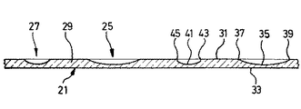
図1は、虚弱線23を有する包装材料21の特に好ましい実施態様を示す。虚弱線23は、ウェブ29によって交互順次に等間隔に形成配置された複数の虚弱点25、27から成る。虚弱点25は、虚弱点27とは別様に設計される。各虚弱点25は、虚弱点27の各々よりもより長く延びていることは明らかである。しかし、虚弱点25、27の幅は、ほぼ等しくされる。しかし、必要ならば、一つの以上の虚弱点の幅はまた、可変であるように選ばれる。虚弱点25、27の間のウェブ29により、虚弱線23は、虚弱線23の縦方向を横断する曲げ応力に強くなることは明らかである。同時に、包装材料21が、切通されずに、単に打出しにされた虚弱点25は、包装材料から成るパックを開放する目的のために、虚弱線23の非常に静寂な破壊まで、物品の気密で衛生上満足される包装を保証する。
【0016】
図2は、虚弱線23による包装材料21の縦断面を示す。包装材料21は、上側31と下側33を有する。長い虚弱点25は、虚弱点25の底部を形成する円弧の形式において縦プロフィル35を有する。縦プロフィル35の2つの端部37、39は、それぞれ、包装材料21の上側31の平面に鋭角で次第に併合する。虚弱点25の底部は、全長にわたって同一幅である。しかし、適切ならば、ここでもまた虚弱点の底部の幅は可変である。
【0017】
虚弱点25と対照的に、各虚弱点27は、浅い略垂直のへこみ43、45による2つの端部の各々において開始し、終端する縦プロフィル41を有する。これらのへこみ43、45の下方端部においてのみ、縦プロフィル41は、円弧の形状に併合する。虚弱点25、27が包装材料21を打出すことにより生成されるならば、対向力が虚弱線23の両側にある包装材料に及ぼされた時、短い虚弱点27のへこみ43、45の領域における包装材料21の構造は、長い虚弱点25の領域におけるよりも、早期に破壊される。虚弱点27がより短いために、破壊力はまた、長い虚弱点25の領域におけるよりも、へこみ43、45の位置においてより早く効力を生ずる。虚弱点25、27の深さは、本質的に同一であり、例えば、包装材料21の厚さの2/3に相当する。
【0018】
しかし、適切ならば、虚弱点25、27の深さはまた、虚弱線の破壊中も雑音を発生させないために、包装材料の材料強度のずっと大きな差異が、虚弱点において望まれるならば、変化する。この形態は、プラスチックホイル又はセロハンからできた包装材料のために適する。
【0019】
図3は、長い虚弱点25の横プロフィル47を示す。横プロフィル47は、U形状溝に本質的に対応し、図2に縦プロフィル35によって形成された底部49を有する。側壁51、53は、包装材料21の上側31の方に開く鋭角を形成する。上側31と側壁51、53によって形成した溝形横プロフィル47の上縦縁は、使用された包装材料21の性質により「丸い」遷移を許容する。記載された例示の実施態様と対照して、必要ならば、各虚弱点は、異なる幅で虚弱な材料を有する。さらに、適切ならば、異なる幅及び深さの虚弱点がまた、順次に設けられる。
【0020】
図4〜図11は、互いに距離をあけて順次に配置された包装材料の虚弱点から成る少なくとも一つの虚弱線を有し、虚弱線の本質的に静寂かつ残留物のない破壊のための手段を設けられた、発明による包装材料のさらに他の例示の実施態様を示す。これらの例示の実施態様において、これらの手段は、同様に、包装材料の変化材料強度の虚弱点から成る。
【0021】
図4〜図9における包装材料の実施態様により、虚弱点における包装材料の変化虚弱ゾーンは、包装材料の構造の虚弱性によって設けられる。
【0022】
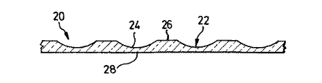
こうして、図4は、包装材料20を示し、その虚弱線は、虚弱線の横断方向において、円弧に対応する縦プロフィル24を有する虚弱点22から成る。この円弧の領域において、包装材料は、最初に、わずかな程度に、それから、次第に大きな程度に、続いてもう一度、次第に小さな程度に虚弱にされ、これらの縮小強度のゾーンの間の遷移は連続である。虚弱点22の間に、図示の如く、包装材料20の部分であるそれぞれのウェブ26が位置し、その厚さは、残りの包装材料の厚さに対応する。図4は、順次に配置され、ウェブ26によって分離された虚弱点22のみを示す。しかし、図4の一連の虚弱点22は、左右に継続することは言うまでもない。弧状縦プロフィルを設けた虚弱点22から成る虚弱線の本質的に静寂な破壊は、対向力が虚弱線の各側に存在する包装材料20の部分に及ぼされる時、該包装材料の破壊は、最初に、最も激しい打出しの位置28において行われる。各虚弱点22の位置28における包装材料20の厚さの不可避な差は、時間をずらした個々の虚弱点28の破壊につながり、その結果、虚弱点22の本質的に静寂な残留物のない破壊が獲得される。
【0023】
発明により、10ミクロン超、特に、20ミクロンの厚さを有するセロハンが、現在、包装材料として好ましい。材料の小厚に拘わらず、驚異的にも、産業生産の枠内で、セロハンを局所的に切通す危険なしに、必要な信頼性を備えて薄厚のセロハンにおいて虚弱点を作ることができることが、示された。これは、当然、衛生的に満足される方法で、外部影響に対して安全に包装されるなければならず、それにも拘わらず、できる限り静寂かつ残留物のない方法で容易に破壊することができる包装を有する、女性用生理用品のタンポン、又は菓子等の食品の如く、衛生物品の包装のために特に重要である。しかし、例えば、ポリプロピレン、ポリエチレン、高圧縮ポリエチレンとプラスチックと紙から成るラミネートの如く、従来のプラスチックとともに、生物学的に劣化性のプラスチックホイルが、この形式のパックのために使用される。
【0024】
図5は、包装材料30における虚弱線の縦プロフィルの修正態様を示し、この場合包装材料30は、上側32と下側34において、円弧の形式におけるそれぞれの虚弱的36と38を設けてある。この場合、円弧の形式における虚弱点36、38の曲率半径は、図4と比較して小さくされ、そして虚弱点36、38の間に延びているウェブ40は、例えば、正確に虚弱点36、38の長さにされることは、明らかである。包装材料30の上側32における虚弱点36は、包装材料30の下側34に設けた虚弱点38と一致するようにされ、その結果、もう一度、材料が最初に破壊される最小厚の位置42は、これらの虚弱点36、38の中途に獲得される。本場合においても、円弧の形式において上側32と下側34においてウェブ40の縦プロフィルを作ることが好ましく、その結果、包装材料30の変化又は縮小強度のゾーンが、連続的に互いに併合する。
【0025】
図6は、包装材料46における虚弱点44のさらに他の実施態様を示し、その上側48において、虚弱点50の縦プロフィルは、Uプロフィルに対応し、その脚52、54は、上側48の方に開く鋭角を形成し、そのプロフィルウェブ56は、脚52、54の高さと比較して長くされる。プロフィルウェブ56の領域において、包装材料46は、材料の名目厚のほぼ3分の1に対応する非常に縮小された厚さを有することは明らかである。
【0026】
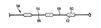
図6に類似する包装材料58のプロフィルが、図7に見られるが、ここでは、図5に類似する方法で、包装材料58には、その上側60において、虚弱点64と、その下側62において虚弱点66を設けられ、これらの虚弱点は、上下に一致し、包装材料58の厚さの中途に共通プロフィルウェブ68があり、その厚さは、包装材料の厚さのほぼ5分の1に対応する。
【0027】
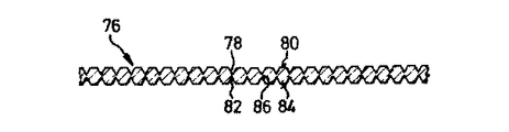
図8は、等長で、虚弱点72の外側の包装材料70の厚さに対応する厚さのプロフィルウェブ74によって分離した三角形縦プロフィルの虚弱点72を虚弱線の縦方向において順次に設けた包装材料のさらに他の実施態様を示す。この形態においても、虚弱点72の深さは変化し、そのため、包装材料70が、虚弱点72における最小厚の領域において亀裂雑音と同時に破壊して開く可能性はない。包装材料76の上側80における虚弱点78と下側84における虚弱点82を有するさらに他の包装材料76が、図9に見られる。もう一度、虚弱点78、82は、上下に一致して配置され、これにより、包装材料76の厚さの中途にプロフィルウェブ86を形成し、その厚さは、包装材料76から生産されたパックが亀裂雑音と同時に開放されるのを防止するために十分に異なる。
【0028】
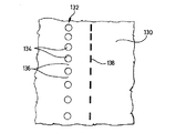
図10は、ウェブとして設計された虚弱点136によって分離された穿孔134を有する虚弱線132を設けた包装材料130のさらに他の実施態様を示す。発明により、この実施態様において、虚弱線132の本質的に静寂な残留物のない破壊のための手段は、個々のウェブのサイズと、このため、穿孔134の間の各ウェブ136の材料厚が、異なるようにされるものである。図10から明らかな如く、個々の穿孔134の間のウェブ形状虚弱点136の長さは、上部から下方に連続的に増大する。穿孔134は包装材料130において穴を構成するが、切れ目138の形式における穿孔が、図10に簡単性のために示された如く好ましい。しかし、適切ならば、通り穴と切れ目がまた、虚弱線132において互いに組み合わされる。上記の如く、時間をずらした虚弱点の破壊を達成するために、ウェブのサイズが可変であることが、できる限り静寂な残留物のない虚弱線の破壊のために本質的である。しかし、穿孔は、同一次元である。
【0029】
虚弱線の可変虚弱化の代替形態が、包装材料140のさらに他の例示の実施態様において図11に示される。ここでもまた、通り穴と等長の切れ目の形式における穿孔142、144が、実施例により示される。図10における実施態様と対照して、ここでは、穿孔142と144によって形成した虚弱線146と148は、グループIにおけるウェブ形状虚弱点とグループIIにおけるウェブ形状虚弱点の2つの順次列から成る。図11におけるウェブ形状虚弱点150と152は、それぞれ、上部から始まり、それぞれのグループI又はIIの端部まで、可変サイズに作成される。本場合に、グループIのウェブ形状虚弱点150とグループIIのウェブ形状虚弱点152のサイズは、両虚弱線146、148において上部から下方に連続的に増大し、グループIとIIの順次の穿孔142、144は、好ましくは、同一サイズにされる。ここでもまた、ウェブ形状虚弱点150の可変長又はサイズは、時間をずらした又は順次の個々の虚弱点150、152の破壊を生じさせる。というのは、小次元の虚弱点は、当然、最初に破壊され、その後、大ウェブ形状虚弱点が破壊され、その結果、包装材料140のこの実施態様においても、虚弱線146と148の本質的に静寂な残留物のない破壊が行われる。もちろん、図4〜図9における例示の実施態様に関して記載された如く、本場合においても、同一又は異なる穿孔を有する複数の虚弱線が、互いに隣接して配置される。
【0030】
パックが、衛生物品、特に、女性用生理用品のタンポンのために意図されるならば、雑音のないことと包装材料の残留物のないことが、特に望ましい。この形式のパックの慎重な取扱いが、個別タンポンパックの収容のための本質的に心理学的な前提条件である。このため、図12(a)〜図12(e)は、少なくとも一つの虚弱線を有し、その虚弱点において、包装材料が可変虚弱性を有する、発明による包装材料を使用するこの形式のタンポンの個別パックの例示の実施態様を示す。
【0031】
こうして、図12(a)は、ウェブ96によって互いにそれぞれ分離された個々の直線虚弱点94から成る虚弱線92を有する個別パック90を示す。虚弱点94は、図1〜図9に示された如く、虚弱線92の縦方向において弧状又はU形状に陥凹にされる。虚弱線92は、後端98から個別パック90の長さの3分の1に設けてある。
【0032】
図12(b)は、個別パック100を示し、その虚弱線102は、互いに隣接して平行に位置してパターンを形成するそれぞれ同一長の直線虚弱点104の対が、個別タンポンパック100の周囲に配置されることにおいてのみ、図12(a)における虚弱線92とは異なる。ウェブ106は、虚弱線102の縦方向において虚弱点104の対をそれぞれ分離する。
【0033】
図12(c)は、互いに隣接して平行に位置し、ウェブ114によって互いに分離され、虚弱パターンを形成する、等長の3つの直線又は帯状虚弱点112から成る虚弱線を有する、タンポンのための個別パック108のさらに他の実施態様を設ける。
【0034】
図12(d)は、個別パック116を示し、この場合虚弱線118は、ウェブ120によって分離された虚弱点122から成り、そして虚弱点は、再び、先行する例示の実施態様における如く、個別パック116の断面において配置されるが、螺旋パターンによりそれぞれ設計される。同時に、虚弱点122は、適切ならば、虚弱線118の周方向において隣接端部と重なり合う。虚弱線118の虚弱パターンのこの設計は、虚弱線118の迅速で本質的に静寂な残留物のない破壊につながる。
【0035】
図12(e)は、タンポンのために個別パック101の例示の実施態様を示し、その虚弱線103は、順次の弧状虚弱点105a、105bから成るパターンを形成する。虚弱点105aは、個別パック101の前端部101aの方向に凸状な弧を形成するが、虚弱点105bは、それぞれ、個別パック101の後端101bの方に凸状に湾曲している。虚弱線103の方向において、弧状虚弱点105a、105bは、ウェブ105cによって比較的小間隔互いに離間される。弧状虚弱点105a、105bは、虚弱線103が破壊されている時、「柔らかい」感覚を使用者に与える。
【0036】
この感覚はまた、図12(f)における虚弱線109のさらに他の実施態様によって強化される。これは、タンポンのための個別パック107を示し、その虚弱線109は、虚弱点111a、111bから成る。虚弱点111aは、もう一度、個別パック107の前端部107aの方向に凸状に湾曲されるが、虚弱点111bはまた、再び、個別パック107の後端部107bの方に凸状にされる。弧状虚弱点111a、111bは、個別パックの周方向において弧状虚弱点の前方と後方に位置する虚弱点の端部が、虚弱点の凸状湾曲に達するように端部で重なり合う。図12(e)と図12(f)により設計された虚弱点は、虚弱線103と109のかなり柔らかい引裂きを許容する。
【0037】
図12(g)は、タンポンのための個別パック113を示し、図12のすべての実施態様における如く、同様に、個別パックの周囲に延びている虚弱線115を設けてある。この実施態様において、虚弱線115は、個別パック113の周方向において互いに関してオフセットされた直線虚弱点117a、117bから成り、互いの背後に位置する直線虚弱点117a、117bの端部は、参照記号117cによって示された如く、相互に重なり合う。虚弱点117a、117bの配置はまた、形成した虚弱線のより柔らかい引裂きを許容する。
【0038】
最後に、非常に柔らかい引裂き効果がまた、図12(h)におけるタンポンの個別パック124で達成され、その虚弱線126は、パターンを形成し、虚弱線126の方向においてV形状な虚弱点128から成る。本事例において、V形状虚弱点128の角頂点と次のV形状虚弱点128の自由端部との重なりがある。もちろん、すでに示された如く、上記の虚弱点の特定設計に拘わらず、虚弱点の相互間隔は、虚弱線のずっと静寂な破壊又は虚弱線の曲げ強度の増大又は低下が望まれるならば変化される。虚弱点を互いに連結するウェブのこの変形は、順次の虚弱点の間のウェブサイズの連続的に増大又は減少する変化から成る。さらに、もちろん、異なる設計の虚弱点を配置するか、又は順次に若しくは特定相互間隔におけるパターンの異なる配置を設けることが可能である。こうして、好ましくは、パックの虚弱線に対して、図1〜図9において示された一つ以上のプロフィルを有する虚弱点を設けることが、完全に可能である。本発明により、打出された虚弱点の領域における包装材料の構造又は穿孔の間の虚弱点を形成するウェブのサイズは、時間をずらした個々の虚弱点の破壊が、獲得され、その結果、各個別パックが、慎重に、すなわち、非常に静寂に開放され、包装材料の残留物が、包装物品、例えば、タンポン、に残されることはないことは本質的である。
【0039】
図13は、女性用生理用品のタンポンのための個別パック160を示し、パックの断面において、異なる長さのウェブ166によって互いに分離された直線カットの形式における穿孔164から成る虚弱線162を示し、その結果、ウェブ166は、個別パック160の開放中、各瞬間において本質的に静寂に破壊される。
【0040】
包装材料の表面のすべり抵抗は、パックの虚弱線の破壊のための本質的な前提条件である。この必要条件を満足するために、図14は、セロハン製の包装材料170の縦断面を示し、その外側171は、粗ラッカーの層172で被覆される。適切ならば、包装材料170の下側は、気密被覆を設けられる。
【0041】
粗ラッカーは、クリアラッカーから成り、その粗構造は、標準無色粒子によって生ずる。セロハン表面の粗構造を生産するためのさらに他の可能性は、印刷機の乾燥段階における反応として粗ラッカーの収縮状乾燥によって与えられる。さらに、セロハン表面の粗構造は、粗ラッカーの乾燥プロセスにおける反応として針状結晶によって生ぜられる。粒子がより大きな粗度を達成するためにラッカー質量に添加される時、これらの粒子は、プラスチックから成る。セロハンの基本仕上げは、材料が包装機構において前層と後層とを熱密封される如く、2つの側面に熱密封層を塗布することを含む。標準密封ラッカーの代わりに、パックの外側を形成するセロハンの側面に密封粗ラッカーを設けることが、好ましく、これにより、粗ラッカーを密封ラッカーの層に塗布するための付加作業を節約する。図15は、図14による粗ラッカー172の層を備え、包装材料170から作られた、個々の虚弱点178から成る虚弱線176を有する、女性用生理用品のタンポンの個別パック174を示す。虚弱線176の両側における矢印AとBは、虚弱線176が破壊されている時、使用者によって及ぼされる対向力を示す。矢印Bに割り当てられたパック174の部分は、タンポン(不図示)の後端部からもぎ取られ、その結果、タンポンに留められ、タンポンの後端部に対して保持された回復テープが、取り外され、タンポンから延ばされる。それから、タンポンは、後端部をつかまれ、そして矢印Aに割り当てられたパック174の前部分が、除去される。指をタンポン端部に挿入することにより、タンポンは、その後、体腔に導入される。個別タンポンパック174の上記の取扱いは、ここで記載されたすべての個別タンポンパックに当てはまる。もちろん、開放するためのパックのこの取扱いはまた、虚弱線の両側に位置するパック部品の対向回転が、包装物品の回りに案内された虚弱線を破壊することができる限り、別の種類の包装物品のために使用される。
【0042】
粗ラッカーから成る外側層のほかに、又は代わりに、包装材料のグリップを改良するために、図16と図17により、包装材料は、少なくとも部分的に機械的な浮出しを設けられる。こうして、図16は、ノブ状高さ182を有する包装材料を示す。浮出しは、丸いノブ頭部183の形式において包装材料180の外面184において突出し、丸いくぼみ188が、内面186において対応している。
【0043】
図17は、包装材料190のさらに他の実施態様を示し、この場合、同様に、丸いノブ状高さ192が包装材料190の外面194から突出するが、本場合に、該高さは、包装材料190の内面198におけるじょうご状くぼみ196によって生成される。
【0044】
図18(a)〜図18(f)は、発明による同一虚弱線204を備えたいろいろな粗化パターンを有する発明による包装材料から成る個別パックを示す。女性用生理用品のタンポンのための個別パック200が、図18(a)に示され、図16又は図17に示された形式の機械的打出しを完全に設けられる。該図における矢印AとBは、図15における如く、再び、開放力の方向を示し、この力により、虚弱線204は、本質的に静寂な残留物のない方法で破壊される。個別パック200のこの表面粗度は、タンポンのための個別パックの所望の即座の本質的に静寂で、このため、慎重な開放を許容する目立つグリップを達成することが理解される。
【0045】
図18(b)は、包装材料がほとんど機械的打出しのない点パターン210の形態において、図16又は図17に示された形式の機械的打出しを示すが、図18(c)において、個別パック220の縦方向に打出し222が設けられ、個別パック220の縦方向に帯状に延びており、包装材料の平行な帯224によって分離され、機械的打出しは設けられない。
【0046】
図18(d)、女性用生理用品のタンポンのための個別パック230を示し、この場合、互いに距離をあけて平行に螺旋状に延びていて、打出しないに中間条片によって分離された機械的打出し232が設けられる。
【0047】
図18(e)により、女性用生理用品のタンポンのためのさらに他の個別パック240において、機械的打出しのクリアな相互に離間したスポット242が、本質的に同一の相互間隔において個別パック240の表面上に分布してある。
【0048】
最後に、図18(f)は、女性用生理用品のタンポンのための個別パック250を示し、この場合、個別パック250の縦方向において相互間隔をあけて配置された機械的打出しの環状帯252を設けている。このため、包装材料の形式と厚さ、及び虚弱線204の設計により、図18(a)による機械的打出しを包装材料に完全に設けるか、又はそうでなければ、図18(b)〜図18(f)に示された如く、この形式の機械的打出しを後者の一部領域のみに装備させることは、得策である。
【0049】
図19〜図21は、包装材料において虚弱点を作るための発明による装置を示し、装置は、その外周において虚弱用歯302を有する円形自由回転式虚弱用ディスク300から成る。本事例において、虚弱用歯302は、図19と図20に示された如く、円弧の形態において外側に湾曲し、虚弱用ディスク300の周囲上に2°のピッチにおいて分布された虚弱用ナイフ縁304を装備している。放射状外側に湾曲した虚弱用ナイフ縁304の曲率半径は、例えば、5mmに等しい。隣接虚弱用歯302の虚弱用ナイフ縁304が、互いに連続的に併合することは明らかであり、内空間306は、虚弱用ディスク300の軸に関して円弧の形態において放射状内側に湾曲し、その内空間306の曲率半径は、当然、虚弱用ナイフ縁のそれよりも実質的に小さいとして計算され、例えば、0.2mmに等しい。
【0050】
図21から、虚弱用歯302の外側虚弱用面308は、虚弱用ディスク300の軸に平行に延びており、その結果、例えば、図1と図3に示された如く、虚弱点において平面又は湾曲底部が、包装材料の虚弱点の領域において生成されることは明らかである。各虚弱用歯302の横プロフィル310は、虚弱用ディスク300の平行な外面312、314まで、虚弱用面308の外側縦縁から広がる。こうして、虚弱用歯302の凸状湾曲虚弱用ナイフ縁304に結合して、包装材料の構造の穏やかな圧縮が行われ、その間、試験により示された如く、包装材料の切通しが、少なくとも10ミクロンの小厚に拘わらず高信頼性に防止される。
【0051】
これへの本質的な寄与は、虚弱用ディスク300の軸に関して円弧の形態において凹状に湾曲した内空間306によって隣接虚弱用歯302の個々の虚弱用ナイフ縁304において形成されたなめらかな遷移によって為される。
【0052】
図19〜図21による虚弱用ディスク300は、さらに以下に記載された虚弱用ディスクと同様に、フリーホイールローラーとして設計されたなめらかな円筒形カウンターローラー301と結合して使用される。カウンターローラー301のなめらかな表面は、好ましくは、例えば、鋼の如く、硬い材料から成り、その結果、所望の虚弱化が、セロハンの構造の部分的破壊の結果として達せられる。しかし、ある状況下で、使用された包装材料、例えば、プラスチックホイルの形式により、例えば、金属合金又はプラスチック被覆から成る柔らかい表面を有するカウンターローラー301がまた、考慮の対象となる。
【0053】
図19〜図21において虚弱用ディスク300を用いてセロハンウェブ316において本発明による虚弱線を作るためのプロセスの例示の実施態様が、図22を参照して以下に記載され、カウンターローラー301は、不図示である。図19において、虚弱用歯302の一つが、セロハンウェブ316に完全に貫通し、対応する虚弱用歯302によってセロハン316の先行する虚弱点318に対して以前に実施されたと同一の方法で虚弱点318を打出しにする。虚弱用歯302は、虚弱用ディスク300の周方向において円弧の形態であるために、各虚弱用歯302は、セロハンウェブ316になめらかに貫通し、セロハンは、各虚弱用歯302の外側虚弱用面308によってその厚さのほぼ3分の1だけ圧縮されるが、切通されない。同時に、上記の如く、比較的もろいことが知られたセロハンの構造が、セロハンが空気又は異物の侵入に対してその気密性を失うことなく、部分的に破壊される。0.2〜0.5mm、好ましくは、0.35mmの各虚弱用歯の幅により、虚弱用ディスク300の少なくとも80mmの直径とこれよりも小さなカウンターローラー301の直径により、満足いく打出し結果が、2〜5バーの打出し圧力が及ぼされた時達成された。
【0054】
一方の側における包装材料の虚弱点打出しに対して、包装材料のウェブが、虚弱用ディスクとカウンターローラーの間の間隙に引き通され、虚弱用ディスクとカウンターローラーは、回転設定される。包装材料が、例えば、上記の図5、図7と図9に示された如く、両側において虚弱点打出しを設けられるならば、虚弱用ディスクとカウンターローラーを同期して駆動することが推奨される。
【0055】
セロハンウェブ316の上側における虚弱点打出し318は、各々、虚弱点底面320を有し、円弧の形態における虚弱用歯304の異なる圧力作用の結果として、前端部においてわずかに傾斜され、これは、セロハン構造のわずかな虚弱化と破壊に対応する。明らかな如く、なめらかな遷移は、各虚弱点318に沿った中途の初期的に軽い打出しと最も重い又は深い打出しの間で発生する。虚弱点318の第2後方長さ部分において、打出しは、全く逆に、すなわち、低い打出し圧力の虚弱点318の縦中心における最も重い打出しから虚弱点318の後端部まで延びており、ここで、打出しは、セロハンウェブ316の非打出し表面になめらかに併合する。セロハン又は別の包装材料の形式、特に、その厚さにより、適切ならば、第1虚弱用ディスク300に同一の第2虚弱用ディスク300が、カウンターローラーとして設けられ、包装材料の下側に対応虚弱点打出しを設ける。この場合、2つの虚弱用ディスクの同期回転駆動が推奨される。類似の性質を有するセロハン又は他の包装材料において発明による虚弱点打出しを形成するためのすべての事象において、虚弱用歯302が、打出しの少なくとも直後に、なめらか又は次第に包装材料に侵入し、破壊の場合に、ある状況下で、材料の非常に細かな粒子のくずれにつながる包装材料の切通しを防止することは重要である。
【0056】
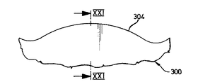
図1〜図3に示された特に都合の良い実施態様の虚弱線23を作製する装置の実施態様が、図23〜図25に示される。この装置の虚弱用ディスク330において、長い虚弱用歯332と短い虚弱用歯334が、その周囲長さにわたって交互に順次に配置される。長い虚弱用歯332と短い虚弱用歯334の間隔は、各場合に同一にされ、本例示実施態様において、例えば、1°に等しい。これから、2つの長い虚弱用歯334と2つの短い虚弱用歯332の間隔は、各場合に2°に等しい。本実施態様において、長い虚弱用歯334は、0.45mm長であり、そして短い虚弱用歯334は、0.2mm長である。図24と図25に特に示された如く、長い虚弱用歯332と短い虚弱用歯334の両方は、放射状外側に湾曲される。長い虚弱用歯334の曲率半径は、2.0mmに等しく、そして短い虚弱用歯334のそれは、0.7mmに等しい。さらに、長い虚弱用歯332の前及び後歯面336、338は、短い虚弱用歯334の周囲の前及び後歯面340、342よりも小さな程度に湾曲され、その結果、長い虚弱用歯332の歯面336、338は、それぞれ、虚弱用ナイフ縁344と鈍角を形成する。これと対照して、歯面340、342は、短い虚弱用歯334の虚弱用ナイフ縁346と直角を形成する。本例示実施態様において、長い虚弱用歯332の前及び後歯面336、338の曲率半径は、0.465mmに等しく、そして短い虚弱用歯334の前及び後歯面340、342の領域における曲率半径は、0.15mmに等しい。長い虚弱用歯332と短い虚弱用歯334の横プロフィルは、図21のそれに対応する。同時に、各虚弱用歯332、334の外側又は作用先端面又は虚弱用面は、図21における虚弱用面308により、0.35mmの幅を有する。
【0057】
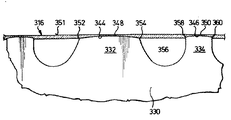
図25は、長い虚弱用歯332と2つの短い虚弱用歯334が、それぞれ、虚弱用ナイフ縁344の半径のセロハンウェブ316に次第に侵入し、そしてセロハンウェブ316から再出現することを明確にする。虚弱用歯332、334の虚弱用ナイフ縁344、346の異なる長さの結果として、対応する長い又は短い虚弱点348、350が獲得され、そして図25が明確に示す如く、長い及び短い虚弱用歯332、334は、セロハン316の厚さのほぼ2/3の深さまでセロハン316の構造を多少とも破壊するが、虚弱用ディスク330とは裏面側のセロハンウェブ316の側面351における構造は、完全に保存され、このため、セロハンによる物品の密封包装を許容する。
【0058】
この虚弱用ディスク330の上記の効果に対して、長い虚弱用歯332と短い虚弱用歯334によって打出された虚弱点348、350が、異なることは重要である。これは、長い虚弱用歯332の各々の前歯縁352と後歯縁354が、虚弱用ディスク330に対面するセロハンウェブ316の表面356のほぼ平面におけるセロハン316に完全に侵入された打出し位置にあるという事実に基づく。対照して、各短い虚弱用歯334の前歯縁358と後歯縁360は、図25に示された短い虚弱用歯334の完全侵入位置において、セロハン316内に位置し、図2に41と43で指定されたへこみを形成するように配置される。図25が示す如く、歯縁358、360は、厚さのほぼ3分の1までセロハン316に侵入している。それぞれの長い虚弱用歯332の前及び後歯縁352、354とそれぞれの短い虚弱用歯334の前及び後歯縁358、360によるセロハンウェブ316の異なる打出しは、該歯縁の4つの侵入点において、薄い材料ウェブを有する虚弱点348と350を生成し、打出し点により形成した虚弱線の破壊中、セロハン316は、時間をずらした、このため、幾らか静寂な方法で破裂する。虚弱用歯332、334の異なる長さの結果として、それらの間の間隔は、上記の如く、同一に保持される。セロハン316が、虚弱線を破壊するために虚弱線の両側において対向力に露呈されるならば、短い虚弱用歯334の配置のために、長い虚弱用歯332の間の材料は、虚弱線の方向において引き伸ばされず、短い虚弱用歯334が、歯縁358、360でセロハン316に侵入し、材料が引裂かれる虚弱点を生成するために破裂する。これは、セロハン316の小残留物の擦り切れ又ははく離を防止する。
【0059】
女性用生理用品のタンポンのためのセロハンパックの試験が行われ、図23〜図25による自由回転式虚弱用ディスク330が使用された。0.35mmの外側虚弱用面の幅を有する虚弱用歯332、334の使用により、最良結果が、セロハンと同様に自由回転式に据え付けた鋼製カウンターローラーに対して虚弱用ディスク330の4.0バールの空気接触圧力において獲得された。セロハンウェブは、虚弱用ディスクとカウンターローラーの間の間隙を通してストックロール(不図示)から150m/minの速度において延伸された。セロハンの厚さは、22/100mmに等しく、打出された虚弱点において、7/1000mmの材料厚が残され、パックの密封を保証する。
【0060】
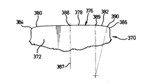
図26と図27は、それぞれ同一サイズと次元の虚弱用歯372を備えた虚弱用ディスク370のさらに他の実施態様を示し、それらの間に、それぞれの同一内空間374が、配置される。虚弱用ディスク370は、再び、少なくとも80mmの直径を有する。この場合、各虚弱用歯372は、4°の弧長にわたっている。内空間374は、周方向において0.35mmの長さを有する。虚弱用歯372は、放射状外側に凸状に湾曲した虚弱用ナイフ縁376を有する。各虚弱用ナイフ縁376は、異なるサイズの3つの湾曲部分、すなわち、中央主要部分378とともに前及び後端部380、382と前及び後かど部分384、386から構成される。虚弱用ナイフ縁378の中央主要部分378は、1.5mmの曲率半径を有する円弧である。中央主要部分378は、1.5mmの全長にわたって虚弱用ナイフ縁372の対称軸387の端点388の両側において、1.5mmの曲率半径を各々有するより鋭い湾曲端部380、382まで延びている。部分382は、点389から点390まで延びており、後かど部分386から後端部382を分離し、その凸状湾曲は、0.1mmの半径を有する。虚弱用ナイフ縁372の他方の端部は、相応して形状付けられる。虚弱用歯372の横プロフィルは、再び、図21のそれに対応し、そして虚弱用歯372の外側虚弱用面は、0.25mmと0.5mm幅の間で変化する。図23と図24における虚弱用歯372の打出し効果は、図20〜図22の長い虚弱用歯332に類似するが、同一ではなく、本実施態様において、かど部分384、386が完全に丸く、このため、虚弱用歯372の各々が、セロハンの如く包装材料になめらかに次第に侵入し、そしてまた、虚弱用歯372の他方の端部により、再び同様に、包装材料を次第に離れる。
【0061】
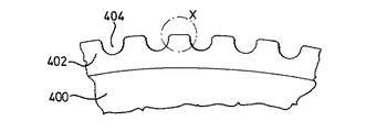
虚弱用ディスク400のさらに他の実施態様が、図28、図29と図30に示される。この虚弱用ディスク400は、4°の弧長の区分を有する虚弱用歯402を有する。虚弱用歯402は、周方向に見た時、虚弱用歯402のほぼ長さにされたウェブ又は内空間404によって互いに分離される。本例示実施態様において、順次の虚弱用歯402の間のクリアな幅は、1.15mmに等しい。図29から、虚弱用歯402の虚弱用ナイフ縁406が、円弧の形態に湾曲された中央主要部分408を有し、虚弱用ナイフ縁406の対称軸411の端部410からそれぞれ前かど部分412と後かど部分414まで0.35mmの長さにわたって延びていることが明らかになる。さらに他の湾曲部分が、中央主要部分408の前端(不指定)と後端416からそれぞれ前方と後方に延びており、そして前述の如く、後湾曲部分のみが指定され、これは、点420まで延びており、この点において、前かど部分412に対応する後丸かど部分414が始まる。前及び後かど部分412、414は、各々、0.1mmの曲率半径を有する。
【0062】
図30は、虚弱用ディスク400の虚弱用歯422の修正態様を示し、この虚弱用歯の虚弱用ナイフ縁424は、中央のわずかに湾曲した長さ部分426を有し、0.2mmの曲率半径を各々を有する丸かど部分428、430が前端と後端に追従している。
【0063】
虚弱用ディスク400の特別な特徴は、虚弱用歯402と422と内空間又はウェブ404とともに外側輪郭が、完全に線侵食されることである。結果として、虚弱用ナイフ縁406の虚弱用面は、虚弱用ディスク400となめらかなカウンターローラー(不図示)の間のセロハンの摩擦連結の改良と、このため、セロハンウェブの打出しの精度の向上を許容する粗度を生ずる。
【0064】
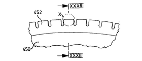
図31、図32と図33は、0.35mmの小相互間隔において配置され、3°の弧長にわたって各々延びている双対の虚弱用歯452、454を有する虚弱用ディスク450のさらに他の形態を示す。双対虚弱用歯452、454は、各々、0.5mmの高さを有し、そして図31に示された如く、虚弱用ディスク450の周方向において等長にされ、図33により、互いに平行に配置され、中央周溝456によって互いに分離される。中央周溝456は、0.5mmの幅を有するが、双対虚弱用歯452、454の外側虚弱用面は、それぞれ、0.3mmに等しい。すべての他の事例において、双対虚弱用歯452、454の外側は、例えば、60°に等しい虚弱用ディスク450の外側縁とテーパ角を形成する。図32により、各双対虚弱用歯452、454は、虚弱用歯452、454の各々の対称軸463の端点462から前かど部分464と後かど部分466まで0.5mmの長さにわたって延びている放射状外側に湾曲した中央主要部分460から成る虚弱用ナイフ縁458を装備している。ここでまた、主要部分460の前端(不図示)と後端468は、端部を伴い、後部のみが470で指定される。双対虚弱用歯452、454の前端と後端におけるこれらの端部は、1.5mmの曲率半径を有する。後端部470の一端472は、0.1mmの曲率半径を有する後かど部分466を伴う。前かど部分464は、対応して丸くされる。双対虚弱用歯452、454によって生成された虚弱点は、セロハン又は同様の包装材料における虚弱点によって形成された虚弱線の破壊において特別な効果を有する。特に、中央周溝456によって形成した非打出し中央ウェブが、双対虚弱用歯452、454の間に残るために、セロハンが虚弱点の領域において破裂する前に、補強せん断効果が虚弱点に及ぼされる。打出しの方法は、こうして、3つの先行する例示実施態様を用いて説明されたものに通ずる。双対虚弱用歯452、454は、丸いかど部分464、466でセロハンになめらか又は次第に侵入し、そして後丸端部縁でなめらかにセロハンから離れる。
【0065】
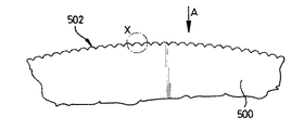
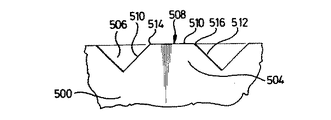
虚弱用ディスク500のさらに他の実施態様が、図34〜図36に示される。この虚弱用ディスク500は、その外側縁において、傾斜歯502を装備し、図34による個々の虚弱用歯504は、虚弱用ディスク500の回転軸502と55°の角度を形成する。傾斜歯502は、それぞれ、1°の弧長に対応する歯分割を有する。虚弱用ディスク500の周囲にわたって測定された、各傾斜虚弱用歯504の長さは、0.27mmに等しい。個々の傾斜虚弱用歯504は、ウェブ又は内空間506によって互いに分離され、隣接虚弱用歯504の相互に対向する直歯面510、517は、90°の角度を形成し、その結果、図36に示された如く、各虚弱用歯504は、台形である。各傾斜虚弱用歯504の前及び後歯面505、507は、それぞれ、平坦虚弱用面508と鈍角を形成し、このため、比較的明白な前縁514と対応する明白な後縁516を形成する。これらの傾斜虚弱用歯504によって形成した虚弱点打出しは、前縁514と後縁516によるセロハンの鋭い切込みと、さらに、虚弱用ディスク500の2つの主要側部に位置する各虚弱用歯504の周縁518、520の比較的強い切込みとを特徴とする。
【0066】
図37と図38は、穿孔ディスクとして、刃部として設計され、周方向において等長の虚弱用歯552を外周に装備している虚弱用ディスク550を示す。しかし、発明により、ウェブ554が、異なる材料厚の虚弱点を形成するために虚弱用歯552の間に生成され、そして本例示実施態様において、この目的のために虚弱用ディスク550の矢印yの周方向において連続的に拡大され、図37において、周方向yにおける最後のウェブ554は、最大長を有する。ウェブ554のこの拡大は、虚弱用ディスク554の周囲の45°のみにわたっており、その結果、各45°の順次周部分Aは、順次に8回のウェブ554の同一連続拡大を有する。言い換えれば、45°の周部分の最大ウェブの端部において、次の周部分が、再び始まり、虚弱用ディスク554の回転方向において最小サイズのウェブ554がある。虚弱用歯552の切込み長は各場合に同一であるために、異なるサイズのゆえに、ウェブ554の破壊が異なる瞬間に順次に行われ、その結果、上記の如く、ウェブ554は、本質的に静寂に順次に個々に破壊し、亀裂雑音に類似する突然の破壊は回避されることは明らかである。なめらかな硬い表面560を有し、自由回転可能なカウンターローラー558は、虚弱用ディスク550に対向して位置する。
【0067】
図37と図38による例示実施態様が、穿孔装置として記載されたが、穿孔ディスク550はまた、単に打出しにより包装材料を虚弱化するディスクとして使用されることは言うまでもなく、また、上記の打出しディスクは、適切な包装材料が使用され、適切ならば、その表面が意図した用途のために適切な硬度を有するカウンターローラーと結合して、対応する高い押圧力が及ぼされるならば、穿孔ディスクとして使用される。しかし、この代替物は、本質的に気密性であるが、すべての場合に、包装物品を汚染から保護するパックが、望まれない又は必要でなく、このため、虚弱線の品質、例えば、パックの静寂な開放に関する厳しい要求は為されない事例において可能性を構成する。上記の虚弱用ディスクによる包装材料の穿孔の場合にも、虚弱用ディスクによって作られた虚弱線が非常に静寂に破壊されることを指摘すれば十分である。
【0068】
本発明の主なる特徴及び態様は以下のとおりである。
【0069】
1.包装材料から生産されたパックを開放するために、順次に距離をあけて配置された虚弱点から成る少なくとも一つ虚弱線を有する包装材料において、虚弱線(23;92;102;110;118;126;132;146;148;162;176;204)が、可変材料強度の虚弱点(22;25;27;36;44;64;66;72;78;82;136;150;152)を有し、その結果、虚弱線が、本質的に静寂に、包装材料(20;21;30;46;58;76;130;140;170;190;201)の残留物のない方法で破壊されることを特徴とする包装材料。
【0070】
2.虚弱点(25、27;136;150;152)が、虚弱線の方向及び/又は横断方向において可変の次元を有することを特徴とする上記1に記載の包装材料。
【0071】
3.虚弱点(22;25;27;36;38)が、本質的に、最初に少なく、それから、大きく、続いて、再び少なく、虚弱線の方向と横断方向において虚弱化されることを特徴とする上記1又は2に記載の包装材料。
【0072】
4.虚弱線の方向に位置する虚弱点(22;25;36)の端部が、虚弱点の間のウェブ(26)に次第に併合することを特徴とする上記1〜3のいずれか一つに記載の包装材料。
【0073】
5.虚弱点(22、25、27;36)が、中央縦区分において見た時、弧状くぼみから成ることを特徴とする上記1〜4のいずれか一つに記載の包装材料。6.虚弱点(27)の端部が、浅い本質的に垂直なへこみ(43、45)によって形成され、それらの間に、虚弱点(27)の底部(49)が延びており、該底部は縦プロフィルにおいて弧状であることを特徴とする上記1又は2に記載の包装材料。
【0074】
7.虚弱点(44;64;66)が、本質的にU形状の縦プロフィルを有することを特徴とする上記1又は2に記載の包装材料。
【0075】
8.虚弱点(72;78)が、V形状縦プロフィルを有することを特徴とする上記1又は2に記載の包装材料。
【0076】
9.虚弱点(36、38;64、66)が、包装材料(30;58;76)の上側(32;60;80)と下側(34;62;84)において設けられることを特徴とする上記1〜8のいずれか一つに記載の包装材料。
【0077】
10.虚弱点(36、38;64、66;78、82)が、上側(32、60;80)と下側(34;62;84)において一致することを特徴とする上記9に記載の包装材料。
【0078】
11.虚弱線の方向において異なる長さを有する虚弱点(25、27)が、順次に交互に配置されることを特徴とする上記8又は9に記載の包装材料。
【0079】
12.同一次元のウェブ(26;29;40)が、虚弱線の方向及び/又は横断方向において虚弱点(22;25、27;28;36、38)の間に配置されることを特徴とする上記1又は4に記載の包装材料。
【0080】
13.虚弱点が、虚弱パターンによって形成されることを特徴とする上記1又は2に記載の包装材料。
【0081】
14.虚弱点が、打出しによって形成されることを特徴とする上記1〜13のいずれか一つに記載の包装材料。
【0082】
15.異なる材料強度の虚弱点(136;150、152)が、異なる次元のウェブによって形成されることを特徴とするウェブによって互いに分離された穿孔から成る少なくとも一つの虚弱線を設けられた上記1に記載の包装材料。
【0083】
16.ウェブ形状虚弱点(136;150、152)が、虚弱線の一方向において次第に大きく/小さくされることを特徴とする上記15に記載の包装材料。
17.虚弱線(146;148)が、その次元が順次に増大/減少する、虚弱点(136;150、152)の少なくとも2つの順次グループ(I、II)から成ることを特徴とする上記16に記載の包装材料。
【0084】
18.包装材料(180)の外側(184)が、グリップを改良するノブ形状高さ(182;192)を少なくとも部分的に設けられることを特徴とする上記1〜17のいずれか一つに記載の包装材料。
【0085】
19.被覆されることを特徴とする上記1〜18のいずれか一つに記載の包装材料。
【0086】
20.被覆が外側層であることを特徴とする上記19に記載の包装材料。
【0087】
21.外側層が、粗ラッカー(172)から成ることを特徴とする上記20に記載の包装材料。
【0088】
22.セロハンから成ることを特徴とする上記1〜21のいずれか一つに記載の包装材料。
【0089】
23.プラスチックから成ることを特徴とする上記1〜22のいずれか一つに記載の包装材料。
【0090】
24.プラスチックが、生物学的に劣化性であることを特徴とする上記23に記載の包装材料。
【0091】
25.10ミクロン厚を超えることを特徴とする上記1〜24のいずれか一つに記載の包装材料。
【0092】
26.厚さが20ミクロンに等しいことを特徴とする上記26に記載の包装材料。
【0093】
27.伸長物品のための個別パックとしての使用を特徴とする上記1〜26のいずれか一つに記載の包装材料。
【0094】
28.女性用生理用品のタンポンのための個別パックとしての使用を特徴とする上記27に記載の包装材料。
【0095】
29.虚弱線が、回復テープを設けたタンポン後端に割り当てられた端部から個別パックの長さのほぼ3分の1の距離に設けられることを特徴とする上記28に記載の包装材料。
【0096】
30.虚弱点が異なる材料強度を備えることを特徴とする、互いに分離された虚弱点を、少なくとも一つの虚弱線の少なくとも縦方向において設けられた、上記1〜29のいずれか一つに記載の包装材料を生産するためのプロセス。
【0097】
31.包装材料の虚弱点の異なる虚弱化が、包装材料の厚さ及び/又は幅の異なる縮小によって生ずることを特徴とする上記30に記載のプロセス。
【0098】
32.包装材料の材料厚が、連続的に変化して縮小されることを特徴とする上記31に記載のプロセス。
【0099】
33.虚弱点が等相互間隔において作られることを特徴とする上記32に記載のプロセス。
【0100】
34.包装材料が、可変間隔において虚弱点を設けられることを特徴とする上記32に記載のプロセス。
【0101】
35.虚弱点の間隔が、虚弱線の一方向において次第に大きく/小さくされることを特徴とする上記34に記載のプロセス。
【0102】
36.虚弱点の少なくとも2つのグループが、形成され、それらの間隔は各グループの一方の端部から他方の端部にそれぞれ増大/減少することを特徴とする上記34又は35に記載のプロセス。
【0103】
37.虚弱点が、包装材料におけるパターンとして作られることを特徴とする上記30〜32のいずれか一つに記載のプロセス。
【0104】
38.包装材料の可変虚弱化が、打出しにより実施されることを特徴とする上記30〜37のいずれか一つに記載のプロセス。
【0105】
39.包装材料が可変間隔において穿孔され、そのため、可変長の結果として、ウェブが、可変材料強度の虚弱点を形成することを特徴とする、少なくとも一つの虚弱線が、包装材料を穿孔することにより作られ、ウェブが穿孔の間に虚弱点を形成する上記30に記載のプロセス。
【0106】
40.虚弱用部材(332、334;372;402;422;504;552)をその外側縁において設けられた回転円形虚弱用ディスク(300;330;370;400;450;480;500;550)を具備し、虚弱用ディスクが、包装材料の走行方向において回転可能に配置され、包装材料が少なくとも一つの虚弱線を作るために通過される間隙を虚弱用ディスクにより形成するカウンターローラー(301;558)を割り当てられることを特徴とする上記1〜30のいずれか一つに記載の包装材料を生産し、かつ上記31〜39のいずれか一つに記載のプロセスを実施するための装置。
【0107】
41.虚弱用ディスクとカウンターローラーが、各々、自由回転可能に据え付けられることを特徴とする上記40に記載の装置。
【0108】
42.虚弱用ディスクとカウンターローラーが、駆動モーターにより同期して駆動されることを特徴とする上記40に記載の装置。
【0109】
43.虚弱用部材が、虚弱用歯(302;332;334;372;402;422;504;552)から成ることを特徴とする上記40に記載の装置。
【0110】
44.虚弱用歯の虚弱用ナイフ縁(304;344;346;376;424;458;482;508)が、虚弱用ディスクの軸に関して放射状外側に弧状に湾曲される虚弱用面(308;510)を有することを特徴とする上記43に記載の装置。
【0111】
45.虚弱用歯(302;332、334)の虚弱用ナイフ縁(304;344、346)が、同一曲率半径を有する円弧の形態においてそれぞれ外側に湾曲することを特徴とする上記44に記載の装置。
【0112】
46.虚弱用歯(332、334;372;402;422)の各虚弱用ナイフ縁(376;424;458)の弧状湾曲が、異なる半径を有する複数の円弧から成ることを特徴とする上記45に記載の装置。
【0113】
47.虚弱用ディスク(370;400;450)の周方向において前方と後方にある虚弱用ナイフ縁の端部(380、382;412、414;464、466)が、虚弱用歯の前及び後歯面の方に丸く(484、386;412、414;428、430)されることを特徴とする上記44〜46のいずれか一つに記載の装置。
【0114】
48.長い虚弱用歯(332)と短い虚弱用歯(334)が、虚弱用ディスク(330)の周方向において異なる曲率半径の虚弱用ナイフ縁(344;346)を設けられることを特徴とする上記43又は44のいずれか一つに記載の装置。
【0115】
49.長い虚弱用歯(332)の虚弱用ナイフ縁(344)の曲率半径が、短い虚弱用歯(334)の曲率半径よりも大きくされることを特徴とする上記48に記載の装置。
【0116】
50.虚弱用歯(370;400;450)の弧状内空間(374;404;554)が、各々、虚弱用ディスクの軸に関して放射状内側に湾曲されることを特徴とする上記45に記載の装置。
【0117】
51.虚弱用ナイフ縁と内空間の曲率半径が、それぞれ、1mmと0.2mmに等しいことを特徴とする上記43〜50のいずれか一つに記載の装置。
【0118】
52.虚弱用ナイフ縁(304;344、346;376;424;458;482;508)の虚弱用面が、0.2〜0.5mm幅であることを特徴とする上記43〜51のいずれか一つに記載の装置。
【0119】
53.虚弱用面が0.35mm幅であることを特徴とする上記52に記載の装置。
【0120】
54.虚弱用歯(552)が、虚弱用ディスク(550)の周方向(y)において次第に拡大/縮小した内空間(554)によって互いに分離されることを特徴とする上記40〜53のいずれか一つに記載の装置。
【0121】
55.虚弱用ディスクの各虚弱用歯の長さが同一にされることを特徴とする上記40に記載の装置。
【0122】
56.虚弱用歯(552)の少なくとも2つのグループが、虚弱用ディスク(550)の等長の周部分(A)において虚弱用ディスク(550)の周方向(y)においてそれぞれ次第に大きく/小さくなる相互間隔(554)で配置されることを特徴とする上記54又は55のいずれか一つに記載の装置。
【0123】
57.虚弱用歯が、共通包絡円において位置することを特徴とする上記40〜56のいずれか一つに記載の装置。
【0124】
58.虚弱用ディスク(300;330;370;400;450;500)が、異なる材料強度の虚弱点を打ち出すための打出しディスクとして設計されることを特徴とする上記40〜57のいずれか一つに記載の装置。
【0125】
59.虚弱用ディスク(550)が、異なる材料強度の虚弱点としてウェブを形成するために、種々の間隔において包装材料を穿孔するための穿孔ディスクとして設計されることを特徴とする上記40〜58のいずれか一つに記載の装置。60.支持部材が、なめらかな表面を有するカウンターローラー(301;558)であることを特徴とする上記40に記載の装置。
【0126】
61.カウンターローラー(301;558)が、硬い金属表面を有することを特徴とする上記60に記載の装置。
【0127】
62.カウンターローラー(301;558)が、弾性変形可能な表面を有することを特徴とする上記61に記載の装置。
【0128】
63.カウンターローラー(301;558)の表面がプラスチックから成ることを特徴とする上記60〜62のいずれか一つに記載の装置。
【0129】
64.カウンターローラーがフリーホイールローラーであることを特徴とする上記40〜63のいずれか一つに記載の装置。
【図面の簡単な説明】
【図1】発明による虚弱線を有する包装材料の部分の斜視図である。
【図2】図1において切断線II−IIに沿った縦断面図である。
【図3】図1において切断線II−IIに沿った断面図である。
【図4】可変縦プロフィルの虚弱点を有する包装材料の虚弱線を通った縦断面図である。
【図5】可変縦プロフィルの虚弱点を有する包装材料の虚弱線を通った縦断面図である。
【図6】可変縦プロフィルの虚弱点を有する包装材料の虚弱線を通った縦断面図である。
【図7】可変縦プロフィルの虚弱点を有する包装材料の虚弱線を通った縦断面図である。
【図8】可変縦プロフィルの虚弱点を有する包装材料の虚弱線を通った縦断面図である。
【図9】可変縦プロフィルの虚弱点を有する包装材料の虚弱線を通った縦断面図である。
【図10】可変サイズのウェブによって互いに分離された穿孔から成る虚弱線を有する包装材料の頂面図である。
【図11】可変サイズのウェブによって互いに分離された穿孔から成る虚弱線を有する包装材料の頂面図である。
【図12】可変虚弱パターンから成る虚弱線を有する、女性用生理用品のタンポンの個別パックの絵画表現図である。
【図13】図10の右側において虚弱線を有する、女性用生理用品のタンポンのための個別パックの図である。
【図14】粗ラッカーから成る外側層を有する包装材料の縦断面図である。
【図15】図14による包装材料から成る女性用生理用品のタンポンの個別パックの図である。
【図16】機械的打出しを有する包装材料の断面図である。
【図17】機械的打出しを有する包装材料の断面図である。
【図18】多様な機械的打出しパターンを有する、女性用生理用品のタンポンの個別パターンの絵画表現図である。
【図19】虚弱用ディスクの第1実施態様の部分図である。
【図20】図19における詳細Xの拡大図である。
【図21】包装材料の異なる虚弱化が種々の虚弱用歯により概略的に示された図20の拡大図である。
【図22】虚弱用ディスクのさらに他の実施態様の部分図である。
【図23】図22の虚弱用ディスクの虚弱用歯の拡大図である。
【図24】カウンターローラーを備えた図23における切断線XXIV−XXIVに沿った断面の部分的に切欠き図である。
【図25】図22による虚弱用ディスクによる包装材料における虚弱線の生成の絵画図である。
【図26】虚弱用ディスクのさらに他の実施態様の部分図である。
【図27】図26の詳細Xの拡大図である。
【図28】図28の詳細Xの拡大図である。
【図29】図28の詳細Xの拡大図である。
【図30】図28の切断線XXX−XXXに沿った断面図である。
【図31】虚弱用ディスクのさらに他の実施態様の部分図である。
【図32】図31の詳細Xの拡大図である。
【図33】図31の詳細Xの別の実施態様の図である。
【図34】虚弱用ディスクのさらに他の実施態様の部分図である。
【図35】図34の矢印Aによる斜角虚弱用歯先端の頂面図である。
【図36】図34の詳細Xの拡大図である。
【図37】カウンターローラーによる虚弱用ディスクのさらに他の実施態様の部分的切欠き図である。
【図38】図37の切欠きAの拡大図である。
【符号の説明】
20 包装材料
21 包装材料
22 虚弱点
23 虚弱線
24 縦プロフィル
25 虚弱点
26 ウェブ
27 虚弱点
28 虚弱点
29 ウェブ
30 包装材料
31 上側
32 上側
33 下側
34 下側
35 縦プロフィル
36 円弧の形態における虚弱点
37 端部
38 円弧の形態における虚弱点
39 端部
40 ウェブ
41 縦プロフィル
42 最小厚の位置
43 へこみ
44 虚弱点
45 へこみ
46 包装材料
47 横プロフィル
48 上側
49 底部
50 虚弱点
51 側壁
52 Uプロフィルの脚
53 側壁
54 Uプロフィルの脚
56 プロフィルウェブ
58 包装材料
60 上側
62 下側
64 虚弱点
66 虚弱点
68 プロフィルウェブ
72 虚弱点
74 プロフィルウェブ
76 包装材料
78 虚弱点
80 上側
82 虚弱点
84 下側
86 虚弱点
90 個別パック
92 虚弱線
94 虚弱点
96 ウェブ
98 個別パックの後端
100 個別パック
101 個別パック
101a 前端
101b 後端
102 虚弱線
103 虚弱線
104 虚弱点の対
105a 虚弱点
105b 虚弱点
105c ウェブ
106 ウェブ
107 個別パック
107a 前端
107b 後端
108 個別パック
109 虚弱線
110 虚弱線
111a 虚弱点
111b 虚弱点
112 虚弱点
113 個別パック
114 ウェブ
115 虚弱線
116 個別パック
117a 直線虚弱点
117b 直線虚弱点
117c オーバーラップ
118 虚弱線
120 ウェブ
122 虚弱点
124 個別パック
126 虚弱線
128 虚弱点
130 包装材料
132 虚弱線
134 穿孔
136 ウェブ
138 切込み線
140 包装材料
142 穿孔
144 穿孔
146 虚弱線
148 虚弱線
150 ウェブ形状虚弱点
152 ウェブ形状虚弱点
160 個別パック
162 虚弱線
164 穿孔
166 ウェブ
170 包装材料
171 外側
172 粗ラッカー/粗ラッカーの層の外側層
174 個別パック
176 虚弱線
178 虚弱点
180 包装材料
182 打出し
183 ノブ頭部
184 包装材料の外側
186 ノブ頭部の内側
188 くぼみ
190 包装材料
192 丸いノブ形状高さ
194 外側
196 じょうご状くぼみ
198 包装材料の内側
200 個別パック
202 機械的打出し/虚弱線
204 虚弱線
210 スポットパターン
220 個別パック
222 帯状打出し
224 帯
230 個別パック
232 機械的打出し
240 個別パック
242 スポット
250 個別パック
252 機械的打出し
300 虚弱用ディスク
301 カウンターローラー
302 虚弱用歯
304 虚弱用ナイフ縁
306 円弧の形態における内空間
308 外側虚弱用面
310 虚弱用歯プロフィル
312 外面
314 外面
316 セロハンウェブ
318 虚弱点
320 虚弱点底部
330 虚弱用ディスク
331 カウンターローラー
332 長い虚弱用歯
334 短い虚弱用歯
336 前後歯面
338 前後歯面
340 前後歯面
342 前後歯面
344 虚弱用ナイフ縁
346 虚弱用ナイフ縁
348 虚弱点打出し
350 虚弱点打出し
352 長い虚弱用歯の前歯縁
354 長い虚弱用歯の後歯縁
356 セロハンの表面
358 短い虚弱用歯の前歯縁
360 短い虚弱用歯の後縁
370 虚弱用ディスク
372 虚弱用歯
374 内空間
376 虚弱用ナイフ縁
378 中央主要部分
380 前端部
382 後端部
384 前かど部分
386 後かど部分
389 点
390 点
400 虚弱用ディスク
402 虚弱用歯
404 内空間
406 虚弱用ナイフ縁
408 主要部分
410 端点
412 前かど部分
414 後かど部分
416 後端
418 後曲線部分
420 点
422 虚弱用歯
424 虚弱用ナイフ縁
426 縦部分
428 丸かど部分
430 丸かど部分
450 虚弱用ディスク
452 双対虚弱用歯
454 双対虚弱用歯
456 周溝
458 虚弱用ナイフ縁
460 主要部分
462 端点
464 前かど部分
466 後かど部分
468 後端
470 後端部
472 後部の端部
500 虚弱用ディスク
501 回転軸
502 傾斜歯
504 虚弱用歯
506 内空間
508 虚弱用面
510 歯面
512 歯面
514 明白な前縁
516 明白な後縁
518 周縁
520 周縁
550 虚弱用ディスク
552 虚弱用歯
554 ウェブ
558 カウンターローラー
560 表面(カウンターローラー)
A 周囲部分[0001]
[Industrial applications]
The present invention relates to a packaging material having at least one weakness line consisting of weakness points that are successively spaced apart to open a produced pack.
[0002]
Packaging materials of this type are, for example, German utility model 91 07 954.3 U1. Is well known. It consists of a flexible plastic foil used to make bags for packaging cellulose-containing hygiene articles, such as napkin pants pressed under inflation pressure. While it is believed that thinning of the material is possible, the frail line preferably consists of perforations in the form of individual bevels or slack holes offset from one another. At the same time, the initial tear area at the orifice of the packaging bag is perforated to tear more easily than the remaining weak lines.
[0003]
The use of cellophane as packaging material for the packaging of hygiene articles, in particular tampon for feminine hygiene products, is known from DE 1,962,733. The cellophane is coated with glue and a vertical cut is made near the glue coating point before the wrapper is rolled up and closed at one end for subsequent storage of the tampon. A handle for opening the pack is provided by penetrating the packaging material just in front of the rear ends of two longitudinal cuts located adjacent to each other.
[0004]
In packs for daily necessities, there is a very high demand for closures that must be closed tightly for a relatively long time to ensure that the pack is not contaminated, if desired, to prevent the contents of the pack from being contaminated. You. Corresponding demands have also been made on the packaging material itself, and in particular cellophane has proven to be suitable. On the other hand, such packs have long been desired to be opened for many years, since the quick and reliable opening of the packs is a necessary prerequisite in this type of pack for mass-consuming mass-produced daily necessities. Perforations were provided at the points. Such perforations allow expansion of the pack contents, at least in part of the hydrophilic material, as a result of the inflow of air and also as a result of the inflow of water vapor contained in the air. In addition, perforations often have weaknesses with respect to bending stress. For the above reasons, packaging materials that allow hermetic welding of packs are increasingly being used. In this connection, the provision of notch lines and tear strips for opening the pack has become known. The production of these packs requires increased use of materials and high expenditure on manufacturing costs. In addition, opening this type of pack is often difficult and time consuming. This is because the tear strip does not lift from the surface of the pack and often even adheres to the pack, so that it is not always found and immediately separated by the consumer.
[0005]
Opening of a cellophane pack along a weak line of perforations is often accompanied by a loud noise similar to a crack. The generation of this noise is undesirable and often perplexing in packs for daily necessities such as sanitary articles such as tampons, which are semi-luxury items, for example, women's sanitary items.
[0006]
For this reason, the object on which the invention is based is to reduce the amount of packaging material required for packs for mass-produced articles, such as semi-luxury articles such as sanitary articles or confectionery products, by using the above-mentioned known general purpose. It is to improve the type of packaging material. At the same time, the pack can be easily opened in a manner that is as quiet and careful as possible, without residue of the packaging material, but nevertheless is relatively stable with respect to bending and impact stress.
[0007]
The invention achieves this object in that the weak line has a weak point of variable material strength, so that the weak line is broken in a manner that is essentially quiet and free of packaging material residue. A reduced intensity zone is provided at each individual weak point. These reduced intensity zones are designed such that each weak point is first light, then heavy, and then lightly embossed in the direction and / or transverse direction of the weak line. A particularly quiet and residue-free destruction of the weak lines is achieved if the reduced strength zones are designed to be continuous and progressively interconnected. At the same time, weak points are provided on the upper and lower sides of the packaging material.
[0008]
According to yet another embodiment of the invention, in the case of a wrapping material provided with at least one weakness line where the weakness points are separated by webs, a variable size of the individual webs between weakness points is provided. Continuous deformation of the web size in one direction of the weak line is preferred for this. If appropriate, a plurality of mutually adjacent lengths of weak lines are provided having webs that increase or decrease in size in one direction of the weak lines. The weak points are arranged at the same or variable length and / or in the form of a pattern. According to the invention, in a particularly advantageous form of the weak line, the weak line is produced by stamping. However, if the type of pressure exerted to create the line of weakness with the packaging material relaxes the requirements for the tightness and / or hygiene of the pack, the weakness can also be a variable dimension between the perforations in the packaging material. Designed as a web.
[0009]
In addition, the packaging material is provided with a punch and provided with a punch which improves the gripping or handling and / or properties of the pack produced from the packaging material. For this purpose, the packaging material is also coated. If it is coated on the outside, the outer layer consists of a coarse lacquer and likewise serves to improve the handling and the tightness of the material. However, the packaging material also has an inner coating that further serves for hermetically sealing the pack contents and / or for easy extraction of the pack contents. In addition, the coating also further contributes to noise attenuation when the pack is opened.
[0010]
According to the invention, cellophane and biologically degradable plastic foil are preferred as packaging materials. At the same time, the packaging material has a thickness of 10-60 microns. A thickness of at least 10 microns is preferred, but a thickness corresponding to at most 20 microns is most preferred.
[0011]
The packaging material according to the invention is particularly suitable as an individual pack for hygiene articles, in particular tampon for feminine hygiene products. This means that the packaging of this type of article with the packaging material according to the invention allows the desired careful, quiet and residue-free opening of the pack, but the articles in the pack are free of contamination and water vapor until they are opened. Because it is protected from.
[0012]
The invention also relates to a process for producing a packaging material provided with weak points located at a distance from one another in at least the longitudinal direction of the at least one weak line. The process is characterized in that the weak point has a variable material strength.
[0013]
Finally, the present invention also relates to an apparatus for producing packaging material and performing the above-mentioned process, characterized in that the apparatus features a rotatable circular frail disk provided with a frail member on its outer edge, The frail disk is assigned a counter-roller rotatable in the direction of travel of the packaging material and forms a gap through which the packaging material is moved to make at least one frail line. The line of weakness and the counter roller are freely rotatably mounted and driven by a web of packaging material that is moved through the gap when the packaging material is provided with a weak point on only one side. In contrast, when the packaging material is provided with weak points created by punching the packaging material on both sides, a synchronous drive of the weak disk and the counter roller is recommended.
[0014]
The invention is described in detail below with a schematic representation of a number of exemplary embodiments of packaging materials and apparatus and processes suitable for making frail lines in packaging materials.
[0015]
【Example】
FIG. 1 shows a particularly preferred embodiment of a
[0016]
FIG. 2 shows a longitudinal section of the
[0017]
In contrast to the points of
[0018]
However, where appropriate, the depth of the
[0019]
FIG. 3 shows the
[0020]
FIGS. 4 to 11 show at least one weak line consisting of weak points of the packaging material arranged one after the other at a distance from one another, and a means for essentially silent and residue-free destruction of the weak lines. 3 shows yet another exemplary embodiment of a packaging material according to the invention, provided with. In these exemplary embodiments, these means likewise consist of weak points of the variable material strength of the packaging material.
[0021]
According to the embodiment of the packaging material in FIGS. 4 to 9, the variation of the packaging material at the point of weakness is defined by the weakness of the structure of the packaging material.
[0022]
FIG. 4 thus shows a
[0023]
According to the invention, cellophane having a thickness of more than 10 microns, especially 20 microns, is presently preferred as packaging material. Regardless of the thickness of the material, surprisingly, it is possible to create a weak point in thin cellophane with the required reliability without the danger of cutting through cellophane locally in the context of industrial production. Was indicated. It must, of course, be packaged safely in a hygienic manner and against external influences and nevertheless be easily destroyed in as quiet and residue-free manner as possible. Of particular importance for the packaging of hygiene articles, such as tampons for feminine hygiene products, or food products such as confectionery, having a possible packaging. However, with conventional plastics, biologically degradable plastic foils are used for this type of pack, such as, for example, a laminate of polypropylene, polyethylene, high compression polyethylene and plastic and paper.
[0024]
FIG. 5 shows a modification of the longitudinal profile of the weak line in the
[0025]
FIG. 6 shows yet another embodiment of the
[0026]
The profile of the
[0027]
FIG. 8 shows
[0028]
FIG. 10 shows yet another embodiment of a
[0029]
An alternative form of variable weakening of the weakness line is shown in FIG. 11 in yet another exemplary embodiment of the
[0030]
If the pack is intended for hygiene articles, in particular tampons for feminine hygiene products, it is particularly desirable for it to be noise-free and free of packaging material residues. Careful handling of this type of pack is essentially a psychological prerequisite for the containment of individual tampon packs. Thus, FIGS. 12 (a) to 12 (e) show a tampon of this type using a packaging material according to the invention, having at least one weakness line at which point the packaging material has a variable weakness. 1 illustrates an exemplary embodiment of an individual pack of the invention.
[0031]
Thus, FIG. 12 (a) shows an
[0032]
FIG. 12 (b) shows the
[0033]
FIG. 12 (c) is for a tampon having a weak line consisting of three equal length straight or band-like
[0034]
FIG. 12 (d) shows an
[0035]
FIG. 12 (e) shows an exemplary embodiment of an individual pack 101 for a tampon, the
[0036]
This sensation is also enhanced by yet another embodiment of the
[0037]
FIG. 12 (g) shows an
[0038]
Finally, a very soft tearing effect is also achieved with the
[0039]
FIG. 13 shows an
[0040]
The slip resistance of the surface of the packaging material is an essential prerequisite for breaking the weak line of the pack. To fulfill this requirement, FIG. 14 shows a longitudinal section of a
[0041]
Coarse lacquers consist of clear lacquers, whose coarse structure is caused by standard colorless particles. Yet another possibility for producing a coarse structure of cellophane surfaces is provided by shrink drying of the coarse lacquer as a reaction in the drying stage of the printing press. In addition, the rough structure of the cellophane surface is produced by needle-like crystals as a reaction in the drying process of the coarse lacquer. When the particles are added to the lacquer mass to achieve greater roughness, they consist of plastic. The basic finish of cellophane involves applying a heat sealing layer to the two sides so that the material is heat sealed between the front and back layers in the packaging mechanism. Instead of a standard sealing lacquer, it is preferred to provide a sealing coarse lacquer on the side of the cellophane forming the outside of the pack, thereby saving the additional work of applying the coarse lacquer to the layer of sealing lacquer. FIG. 15 shows an
[0042]
In addition to or instead of the outer layer of coarse lacquer, in order to improve the grip of the packaging material, according to FIGS. 16 and 17, the packaging material is at least partially provided with a mechanical relief. Thus, FIG. 16 shows a packaging material having a knob-
[0043]
FIG. 17 shows yet another embodiment of the
[0044]
18 (a) to 18 (f) show individual packs of packaging material according to the invention having various roughening patterns with the same
[0045]
FIG. 18 (b) shows a mechanical embossment of the type shown in FIG. 16 or FIG. 17 in the form of a
[0046]
FIG. 18 (d) shows an
[0047]
According to FIG. 18 (e), in yet another
[0048]
Finally, FIG. 18 (f) shows an
[0049]
19 to 21 show a device according to the invention for creating a weak point in a packaging material, the device comprising a circular free-rotating
[0050]
From FIG. 21, the
[0051]
An essential contribution to this is due to the smooth transitions formed at the individual weakening knife edges 304 of
[0052]
The
[0053]
An exemplary embodiment of a process for making a weak line according to the present invention in a
[0054]
For punching the weakness of the packaging material on one side, a web of packaging material is drawn through the gap between the weakness disk and the counter roller, and the weakness disk and the counter roller are set to rotate. If the packaging material is provided with a weak spot punch on both sides, for example as shown in FIGS. 5, 7 and 9 above, it is recommended to drive the weak disk and the counter roller synchronously. You.
[0055]
The weak point punches 318 on the upper side of the
[0056]
An embodiment of the apparatus for making the
[0057]
FIG. 25 clarifies that the long
[0058]
It is important that the
[0059]
Tests of cellophane packs for tampons of feminine hygiene products were performed, using a free-rotating
[0060]
FIGS. 26 and 27 show yet another embodiment of a
[0061]
Yet another embodiment of the frail disk 400 is shown in FIGS. 28, 29 and 30. The weakness disk 400 has
[0062]
FIG. 30 shows a modification of the
[0063]
A particular feature of the weakness disk 400 is that the outer contours together with the
[0064]
FIGS. 31, 32 and 33 show yet another form of a
[0065]
Yet another embodiment of a
[0066]
FIGS. 37 and 38 show a
[0067]
Although the exemplary embodiment according to FIGS. 37 and 38 has been described as a perforating device, it will be appreciated that the
[0068]
The main features and aspects of the present invention are as follows.
[0069]
1. A frangible line (23; 92; 102; 110; 118;) in a packaging material having at least one frangible line of weak points sequentially spaced to open a pack produced from the packaging material. 126; 132; 146; 148; 162; 176; 204) are the weak points of the variable material strength (22; 25; 27; 36; 44; 64; 66; 72; 78; 82; 136; 150; 152). So that the frail lines are destroyed in an essentially quiet manner in a residue-free manner of the packaging material (20; 21; 30; 46; 58; 76; 130; 140; 170; 190; 201). Packaging material characterized by the fact that:
[0070]
2. Packaging material according to claim 1, characterized in that the weak points (25, 27; 136; 150; 152) have a variable dimension in the direction of the weak line and / or in the transverse direction.
[0071]
3. The point of weakness (22; 25; 27; 36; 38) is characterized in that it is essentially weak at first, then large and subsequently again weak, in the direction of the weak line and in the transverse direction. 3. The packaging material according to 1 or 2 above.
[0072]
4. The end of the weak point (22; 25; 36) located in the direction of the weak line gradually merges with the web (26) between the weak points, as described in any one of the above items 1 to 3, Packaging material.
[0073]
5. A packaging material according to any one of the preceding claims, characterized in that the weak points (22, 25, 27; 36), when viewed in the central longitudinal section, consist of arc-shaped depressions. 6. The end of the weak point (27) is formed by a shallow essentially vertical indentation (43, 45), between which the bottom (49) of the weak point (27) extends, said bottom being vertical 3. The packaging material as described in 1 or 2 above, wherein the packaging material has an arc shape in the profile.
[0074]
7. A packaging material according to claim 1 or 2, characterized in that the weak point (44; 64; 66) has an essentially U-shaped vertical profile.
[0075]
8. 3. The packaging material according to the above item 1 or 2, wherein the weak point (72; 78) has a V-shaped vertical profile.
[0076]
9. The weak point (36, 38; 64, 66) is provided on the upper side (32; 60; 80) and the lower side (34; 62; 84) of the packaging material (30; 58; 76). 9. The packaging material according to any one of 1 to 8.
[0077]
10. The packaging material according to the above item 9, wherein the weak points (36, 38; 64, 66; 78, 82) coincide with each other on the upper side (32, 60; 80) and the lower side (34; 62; 84). .
[0078]
11. The packaging material according to the above item 8 or 9, wherein the weak points (25, 27) having different lengths in the direction of the weak line are sequentially and alternately arranged.
[0079]
12. A web (26; 29; 40) of the same dimension is arranged between the weak points (22; 25, 27; 28; 36, 38) in the direction of the weak line and / or in the transverse direction. 5. The packaging material according to 1 or 4.
[0080]
13. 3. The packaging material according to the above 1 or 2, wherein the weak point is formed by a weak pattern.
[0081]
14. 14. The packaging material as described in any one of 1 to 13 above, wherein the weak point is formed by punching.
[0082]
15. The weak point of different material strength (136; 150, 152) is provided with at least one weak line consisting of perforations separated from each other by webs, characterized by being formed by webs of different dimensions. Packaging material.
[0083]
16. 16. The packaging material according to the above 15, wherein the web shape weak points (136; 150, 152) are gradually increased / decreased in one direction of the weak line.
17. The weakness line (146; 148) consists of at least two sequential groups (I, II) of weakness points (136; 150, 152) whose dimensions increase / decrease sequentially. Packaging material.
[0084]
18. Package according to any of the preceding claims, characterized in that the outer side (184) of the packaging material (180) is at least partially provided with knob-shaped heights (182; 192) for improving grip. material.
[0085]
19. 19. The packaging material according to any one of the above items 1 to 18, which is coated.
[0086]
20. 20. The packaging material according to the above item 19, wherein the coating is an outer layer.
[0087]
21. The packaging material according to
[0088]
22. 22. The packaging material according to any one of the above items 1 to 21, which is made of cellophane.
[0089]
23. 23. The packaging material according to any one of the above items 1 to 22, which is made of plastic.
[0090]
24. 24. The packaging material according to the
[0091]
25. The packaging material as described in any one of the above items 1 to 24, wherein the packaging material has a thickness of more than 10 microns.
[0092]
26. 27. The packaging material of
[0093]
27. 27. The packaging material as described in any one of the above items 1 to 26, characterized in that it is used as an individual pack for an elongated article.
[0094]
28. 28. The packaging material as described in 27 above, characterized in that it is used as an individual pack for a tampon for feminine hygiene products.
[0095]
29. 29. The packaging material of
[0096]
30. The packaging material according to any one of 1 to 29, wherein the weak points have different material strengths, and the weak points separated from each other are provided in at least a longitudinal direction of at least one weak line. Process for producing.
[0097]
31. 31. The process according to
[0098]
32. 32. The process according to above 31, wherein the material thickness of the packaging material is continuously varied and reduced.
[0099]
33. 33. The process of
[0100]
34. 33. The process according to
[0101]
35. 35. The process of
[0102]
36. Process according to claim 34 or 35, characterized in that at least two groups of weak points are formed, the distance between which increases / decreases from one end of each group to the other end, respectively.
[0103]
37. 33. The process according to any one of
[0104]
38. The process according to any one of
[0105]
39. The packaging material is perforated at variable intervals, so that at least one weak line formed by perforating the packaging material is characterized by the web forming a weak point of variable material strength as a result of the variable length. 31. The process according to
[0106]
40. A frangible member (332, 334; 372; 402; 422; 504; 552) is provided at its outer edge with a rotating circular frail disk (300; 330; 370; 400; 450; 480; 500; 550). And a counter roller (301; 558) in which the frail disk is rotatably arranged in the direction of travel of the packaging material and forms a gap through which the packaging material is passed to create at least one frail line. An apparatus for producing a packaging material according to any one of the above 1 to 30 and performing a process according to any one of the above 31 to 39, characterized in that it is assigned.
[0107]
41. 41. The apparatus according to the
[0108]
42. 41. The apparatus according to the
[0109]
43. 41. The apparatus of
[0110]
44. The weakening knife edge (304; 344; 346; 376; 424; 458; 482; 508) of the weakening tooth has a weakening surface (308; 510) which is curved radially outwardly with respect to the axis of the weakening disk. 44. The apparatus according to the
[0111]
45. 45. Apparatus according to
[0112]
46. 45. The arc of
[0113]
47. The edges (380, 382; 412, 414; 464, 466) of the fragile knife edge anteriorly and posteriorly in the circumferential direction of the fragile disk (370; 400; 450) correspond to the front and rear flanks of the fragile tooth. 47. The apparatus of any of the above items 44-46, wherein the device is rounded (484,386; 412,414; 428,430).
[0114]
48. 43. The above-mentioned 43, characterized in that the long weak teeth (332) and the short weak teeth (334) are provided with weak knife edges (344; 346) having different radii of curvature in the circumferential direction of the weak disk (330). Or the apparatus of any one of 44.
[0115]
49. 49. The apparatus according to
[0116]
50. The apparatus of
[0117]
51. 51. Apparatus according to any of the
[0118]
52. Any one of the
[0119]
53. 53. The apparatus of
[0120]
54. Any one of the
[0121]
55. 41. The apparatus according to
[0122]
56. At least two groups of frail teeth (552) are progressively larger / smaller in the circumferential direction (y) of the frail disk (550) at equal length circumferential portions (A) of the frail disk (550). The device according to any one of the
[0123]
57. 57. Apparatus according to any of the
[0124]
58. The weak disk (300; 330; 370; 400; 450; 500) may be designed as a punching disk for punching weak points of different material strengths. The described device.
[0125]
59. Any of the preceding claims 40-58, wherein the weakness disc (550) is designed as a perforated disc for perforating the packaging material at various intervals to form a web as a weak point of different material strength. An apparatus according to any one of the preceding claims. 60. 41. Apparatus according to
[0126]
61. The apparatus according to
[0127]
62. 61. The apparatus according to the above item 61, wherein the counter roller (301; 558) has an elastically deformable surface.
[0128]
63. 63. The apparatus according to any one of the
[0129]
64. The device according to any one of the
[Brief description of the drawings]
FIG. 1 is a perspective view of a portion of a packaging material having a weak line according to the invention.
FIG. 2 is a longitudinal sectional view taken along a cutting line II-II in FIG.
FIG. 3 is a sectional view taken along section line II-II in FIG.
FIG. 4 is a longitudinal sectional view through a weak line of a packaging material having a weak point of a variable vertical profile.
FIG. 5 is a longitudinal sectional view through a weak line of a packaging material having a weak point of a variable vertical profile.
FIG. 6 is a longitudinal sectional view through a weak line of a packaging material having a weak point of a variable vertical profile.
FIG. 7 is a longitudinal sectional view of a packaging material having a weak point of a variable vertical profile through a weak line.
FIG. 8 is a longitudinal sectional view through a weak line of a packaging material having a weak point of a variable vertical profile.
FIG. 9 is a longitudinal sectional view of a packaging material having a weak point of a variable vertical profile through a weak line.
FIG. 10 is a top view of a packaging material having frail lines of perforations separated from one another by a variable size web.
FIG. 11 is a top view of a packaging material having frail lines of perforations separated from each other by a variable size web.
FIG. 12 is a pictorial representation of an individual pack of tampon for feminine hygiene, with frail lines consisting of variable frail patterns.
FIG. 13 is a view of an individual pack for a tampon of feminine hygiene products with a frail line on the right side of FIG. 10;
FIG. 14 is a longitudinal sectional view of a packaging material having an outer layer of coarse lacquer.
FIG. 15 is a view of an individual pack of tampon for feminine hygiene comprising the packaging material according to FIG. 14;
FIG. 16 is a sectional view of a packaging material having a mechanical embossing.
FIG. 17 is a sectional view of a packaging material having a mechanical embossing.
FIG. 18 is a pictorial representation of an individual pattern of a tampon of a feminine hygiene product having various mechanical embossing patterns.
FIG. 19 is a partial view of a first embodiment of a frail disk.
FIG. 20 is an enlarged view of a detail X in FIG. 19;
FIG. 21 is an enlarged view of FIG. 20, wherein different weakenings of the packaging material are schematically illustrated by various weakening teeth;
FIG. 22 is a partial view of yet another embodiment of a frail disk.
FIG. 23 is an enlarged view of a frail tooth of the frail disk of FIG. 22;
FIG. 24 is a partially cutaway view of a section taken along section line XXIV-XXIV in FIG. 23 with a counter roller.
FIG. 25 is a pictorial diagram of the generation of a weak line in a packaging material by the weak disk according to FIG. 22;
FIG. 26 is a partial view of yet another embodiment of a frail disk.
FIG. 27 is an enlarged view of a detail X of FIG. 26;
FIG. 28 is an enlarged view of a detail X in FIG. 28;
FIG. 29 is an enlarged view of a detail X of FIG. 28;
FIG. 30 is a sectional view taken along section line XXX-XXX in FIG. 28;
FIG. 31 is a partial view of yet another embodiment of a frail disk.
FIG. 32 is an enlarged view of a detail X in FIG. 31;
FIG. 33 is a view of another embodiment of detail X of FIG. 31.
FIG. 34 is a partial view of yet another embodiment of a frail disk.
FIG. 35 is a top view of the tip of the bevelling weakness tooth indicated by arrow A in FIG.
FIG. 36 is an enlarged view of a detail X of FIG. 34;
FIG. 37 is a partial cutaway view of yet another embodiment of a frail disk with a counter roller.
FIG. 38 is an enlarged view of a notch A in FIG. 37.
[Explanation of symbols]
20 Packaging materials
21 Packaging materials
22 Weak Points
23 Frail Line
24 vertical profile
25 Weak Points
26 Web
27 Frailty
28 Weakness
29 Web
30 Packaging materials
31 Upper
32 upper side
33 lower side
34 lower side
35 vertical profile
36 Weak points in the form of a circular arc
37 end
38 Weak point in the form of a circular arc
39 end
40 Web
41 vertical profile
42 Minimum thickness position
43 dent
44 Weakness
45 dent
46 Packaging materials
47 Horizontal Profile
48 Upper side
49 bottom
50 weak points
51 Side wall
52 U Profile Leg
53 Side wall
54 U Profile Leg
56 Profile Web
58 Packaging materials
60 upper side
62 lower side
64 Weakness
66 Frail
68 Profile Web
72 Weak Point
74 Profile Web
76 Packaging materials
78 Weakness
80 upper side
82 Weakness
84 lower side
86 Weakness
90 individual packs
92 Frail Line
94 Frail
96 Web
98 Back end of individual pack
100 individual packs
101 individual packs
101a front end
101b rear end
102 Weak Line
103 Frail Line
104 Pair of Weak Points
105a weak point
105b weak point
105c Web
106 Web
107 individual packs
107a front end
107b rear end
108 individual packs
109 Frail Line
110 Frail
111a weak point
111b weak point
112 Weakness
113 individual packs
114 Web
115 Frail
116 individual packs
117a Straight line weak point
117b Straight line weak point
117c overlap
118 Frail
120 web
122 Weak Point
124 individual packs
126 Frail Line
128 weakness
130 Packaging materials
132 Frail Line
134 perforation
136 Web
138 score line
140 Packaging material
142 perforation
144 perforation
146 Frail Line
148 frail line
150 Web shape weak point
152 Web shape weak point
160 individual packs
162 frail line
164 perforation
166 Web
170 Packaging materials
171 outside
172 outer layer of coarse lacquer / coarse lacquer layer
174 individual packs
176 Frail Line
178 Weakness
180 Packaging materials
182 Launch
183 knob head
184 Outside packaging material
186 inside knob head
188 hollow
190 Packaging materials
192 Round knob shape height
194 outside
196 Funnel-shaped hollow
198 Inside of packaging material
200 individual packs
202 Mechanical launch / weak line
204 Frail
210 spot pattern
220 individual packs
222 strip
224 obi
230 individual packs
232 Mechanical launch
240 individual packs
242 spots
250 individual packs
252 Mechanical launch
300 disk for weakness
301 counter roller
302 Frail Tooth
304 Knife Edge for Weakness
306 Interior space in the form of arc
308 Outside weakness surface
310 Frail Tooth Profile
312 exterior
314 outer surface
316 Cellophane Web
318 Weakness
320 Weak Point Bottom
330 disk for weakness
331 counter roller
332 Long Frail Tooth
334 Short Frail Tooth
336 front and rear tooth surface
338 front and rear tooth surface
340 front and rear tooth surfaces
342 front and rear tooth surface
344 Frail Knife Edge
346 Frail Knife Edge
348 Weak point launch
350 Weak point launch
352 Front edge of long weak teeth
354 posterior margin of long weak teeth
356 Cellophane surface
358 Front edge of short frail tooth
360 trailing edge of short frail tooth
370 Frail Disk
372 Frail Tooth
374 interior space
376 Frail Knife Edge
378 Central main part
380 front end
382 rear end
384 front corner
386 Rear corner
389 points
390 points
400 disk for weakness
402 Frail Tooth
404 Interior Space
406 Frail Knife Edge
408 Main part
410 endpoint
412 Front corner
414 Back corner
416 rear end
418 Back curve part
420 points
422 Frail Tooth
424 knife edge for weakness
426 vertical part
428 round corner
430 round corner
450 disk for weakness
452 Dual Frail Teeth
454 Dual Frail Teeth
456 circumferential groove
458 Frail Knife Edge
460 main part
462 endpoint
464 front corner
466 Rear corner
468 rear end
470 rear end
472 rear end
500 disk for weakness
501 Rotation axis
502 Inclined tooth
504 Frail teeth
506 Interior space
508 Face for weakness
510 tooth surface
512 tooth surface
514 Clear Leading Edge
516 apparent trailing edge
518 rim
520 margin
550 Frail Disk
552 Frail Tooth
554 Web
558 counter roller
560 surface (counter roller)
A Surrounding part
Claims (1)
Applications Claiming Priority (2)
| Application Number | Priority Date | Filing Date | Title |
|---|---|---|---|
| DE4237795.1 | 1992-11-09 | ||
| DE4237795A DE4237795A1 (en) | 1992-11-09 | 1992-11-09 | Packaging material with at least one line of weakness and method and device for producing the same |
Publications (2)
| Publication Number | Publication Date |
|---|---|
| JPH06211267A JPH06211267A (en) | 1994-08-02 |
| JP3565883B2 true JP3565883B2 (en) | 2004-09-15 |
Family
ID=6472443
Family Applications (1)
| Application Number | Title | Priority Date | Filing Date |
|---|---|---|---|
| JP29911093A Expired - Fee Related JP3565883B2 (en) | 1992-11-09 | 1993-11-05 | Packaging material having at least one weak line and production process and apparatus therefor |
Country Status (16)
| Country | Link |
|---|---|
| EP (1) | EP0597446B1 (en) |
| JP (1) | JP3565883B2 (en) |
| AT (1) | ATE165301T1 (en) |
| AU (2) | AU5043293A (en) |
| BR (1) | BR9304475A (en) |
| CA (1) | CA2109128C (en) |
| DE (2) | DE4237795A1 (en) |
| DK (1) | DK0597446T3 (en) |
| EC (1) | ECSP930997A (en) |
| ES (1) | ES2116386T3 (en) |
| GR (1) | GR930100419A (en) |
| HK (1) | HK1008738A1 (en) |
| IL (1) | IL107369A0 (en) |
| MY (1) | MY130097A (en) |
| TR (1) | TR28820A (en) |
| TW (1) | TW257738B (en) |
Families Citing this family (40)
| Publication number | Priority date | Publication date | Assignee | Title |
|---|---|---|---|---|
| SE506164C2 (en) | 1995-10-09 | 1997-11-17 | Medscand Medical Ab | Instruments for the treatment of urinary incontinence in women |
| NZ264939A (en) * | 1994-11-17 | 1997-11-24 | Carter Holt Harvey Ltd | Wrapper for paper roll; the wrapper extends circumferentially around the periphery of the roll and comprises a line of perforation to facilitate its removal |
| DE19941427A1 (en) | 1999-08-30 | 2001-03-01 | Hoechst Trespaphan Gmbh | packaging |
| DE20121759U1 (en) | 2001-03-26 | 2003-05-22 | Johnson & Johnson Gmbh | Tampon for feminine hygiene, has insertion end, recovery end, recovery tape and solid core having uncompressed longitudinal ribs separated by longitudinal grooves which are spirally shaped |
| US6716203B2 (en) | 2001-12-18 | 2004-04-06 | Kimberly-Clark Worldwide, Inc. | Individual absorbent articles wrapped in a quiet and soft package |
| DE10214579A1 (en) * | 2002-04-02 | 2003-10-23 | Johnson & Johnson Gmbh | Packaging material sheet with at least one line of weakness and packaging material |
| US6955665B2 (en) | 2002-05-23 | 2005-10-18 | The Procter & Gamble Company | Tampon wrapper with improved opening means |
| US7897219B2 (en) | 2004-06-01 | 2011-03-01 | Automated Packaging Systems, Inc. | Web and method for making fluid filled units |
| ES2608877T3 (en) * | 2004-06-01 | 2017-04-17 | Automated Packaging Systems, Inc | Band and procedure to perform fluid-filled units |
| DE102004036058A1 (en) * | 2004-07-24 | 2006-02-16 | Hysalma Hygiene Sales + Marketing Gmbh | Packaging of a hygiene article, in particular a menstruation tampon |
| US20060071057A1 (en) * | 2004-09-30 | 2006-04-06 | Kimberly-Clark Worldwide, Inc. | Frangible seal for packaging |
| DK1650137T3 (en) * | 2004-10-20 | 2011-07-04 | Amcor Flexibles Europe | Packaging that has a breaking line |
| DE102005036749A1 (en) * | 2005-08-04 | 2007-02-15 | Stockhorst, Ch., Dipl.-Ing.(FH) | Material used as a sugar stick for preparing drinks has a perforation with openings tapering on one side |
| US7422105B2 (en) * | 2005-12-30 | 2008-09-09 | Kimberly-Clark Worldwide, Inc. | Packaged tampon and applicator assembly |
| DE102006015238A1 (en) * | 2006-03-30 | 2007-10-04 | S&C Polymer Silicon- und Composite-Spezialitäten GmbH | Disposable packaging for storage, mixing and extraction of multi-component materials for e.g. medicinal and dental applications, includes membrane ruptured by pointed object to permit mixing |
| BRPI0719782B8 (en) | 2006-10-12 | 2021-06-22 | Mcneil Ppc Inc | process for wrapping a menstrual device and apparatus for closing a wrapping material around a rounded end of a menstrual tampon |
| US8302844B2 (en) | 2006-11-20 | 2012-11-06 | The Procter & Gamble Company | Wrapper having a predetermined line of weakness |
| US8075512B2 (en) | 2007-04-13 | 2011-12-13 | The Procter & Gamble Company | Applicator having an enhanced gripping region |
| US8840598B2 (en) | 2007-09-12 | 2014-09-23 | The Procter & Gamble Company | Wrapper having a tab |
| US8113730B2 (en) | 2007-09-17 | 2012-02-14 | The Tapemark Company | Dispensing package with applicator |
| WO2009040629A2 (en) * | 2007-09-24 | 2009-04-02 | Diapack Limited | Break-open single-dose sealed package |
| EP2209614B1 (en) | 2007-10-31 | 2015-08-19 | Automated Packaging Systems, Inc. | Web and method for making fluid filled units |
| US20090247981A1 (en) * | 2008-03-28 | 2009-10-01 | Playtex Products, Inc. | Tampon package and method for making the same |
| DE102008020640B4 (en) | 2008-04-24 | 2010-09-09 | Frank Ruhlmann | tampon |
| GB0818122D0 (en) * | 2008-10-03 | 2008-11-05 | Innovia Films Ltd | Overwrap film |
| GB0818124D0 (en) * | 2008-10-03 | 2008-11-05 | Innovia Films Ltd | Packaging film |
| CN103784259B (en) | 2008-11-26 | 2016-05-18 | 麦克内尔-Ppc股份有限公司 | Tampon overwrap |
| WO2010062827A1 (en) * | 2008-11-26 | 2010-06-03 | Mcneil-Ppc, Inc. | Sealing pattern for tampon overwrap |
| US8814430B2 (en) | 2010-02-23 | 2014-08-26 | Kraft Foods R&D, Inc. | Food package having opening feature |
| DE202010005748U1 (en) * | 2010-04-19 | 2011-09-02 | British American Tobacco (Germany) Gmbh | Creasing |
| PL2913281T3 (en) * | 2010-07-09 | 2017-08-31 | Intercontinental Great Brands Llc | Package for stacked product pieces having a pattern of severable locations |
| GB2488782A (en) * | 2011-03-07 | 2012-09-12 | L C S Tech Ltd | Stronger Breaking Line |
| DE102011050221A1 (en) * | 2011-05-09 | 2012-11-15 | Huhtamaki Ronsberg, Zweigniederlassung Der Huhtamaki Deutschland Gmbh & Co. Kg | Film material for the production of a packaging as well as methods of production and use |
| AU2012278849B2 (en) | 2011-07-07 | 2016-12-22 | Automated Packaging Systems, Inc. | Air cushion inflation machine |
| FR2984211B1 (en) * | 2011-12-15 | 2015-08-07 | Faurecia Interieur Ind | DEVICE FOR FORMING AN AFFECTED AREA IN A COATING LAYER. |
| MX2015011259A (en) | 2013-03-15 | 2016-02-03 | Automated Packaging Syst Inc | On-demand inflatable packaging. |
| US9994376B2 (en) * | 2013-10-29 | 2018-06-12 | The Procter & Gamble Company | Package comprising a plurality of individually wrapped articles |
| CA2931243A1 (en) | 2013-11-21 | 2015-05-28 | Automated Packaging Systems, Inc. | Air cushion inflation machine |
| DE102016106354A1 (en) | 2016-04-07 | 2017-10-12 | Hygiene Oederan Produktionsgesellschaft mbH | Packed tampon |
| EP3868347A1 (en) * | 2020-02-21 | 2021-08-25 | Ontex BV | Absorbent articles having single-handed opening and methods |
Family Cites Families (25)
| Publication number | Priority date | Publication date | Assignee | Title |
|---|---|---|---|---|
| US2236366A (en) * | 1938-11-02 | 1941-03-25 | Lester & Wasley Co Inc | Machine for treating paper |
| US2546698A (en) * | 1943-10-20 | 1951-03-27 | Nicolic Charles | Sheet material with weakened tearing line |
| DE841258C (en) * | 1949-08-30 | 1952-06-13 | Alfons Miller | Rice opener |
| US2769496A (en) * | 1951-11-23 | 1956-11-06 | Spinner Isidore | Rotary cutting die for perforating signatures |
| US2750102A (en) * | 1953-12-04 | 1956-06-12 | Truman D Thurman | Envelope |
| US3014631A (en) * | 1958-12-22 | 1961-12-26 | St Regis Paper Co | Fruit lug liner |
| US3409206A (en) * | 1967-03-17 | 1968-11-05 | Continental Can Co | Container blank, body, and method of forming |
| US3522754A (en) * | 1967-08-14 | 1970-08-04 | Centenary Central | Reinforced freewheeling resilient cover for rotary die-cutting anvil |
| CH494095A (en) * | 1968-08-05 | 1970-07-31 | B Vereinigte Elektrobetr E Ger | Method and device for perforating materials |
| FR1600719A (en) * | 1968-12-20 | 1970-07-27 | ||
| CH512378A (en) * | 1969-07-02 | 1971-09-15 | Auer Michel | Packaging for food products, in particular for fatty substances, and method of manufacturing this packaging |
| US4050362A (en) * | 1974-07-05 | 1977-09-27 | Friedrich Schroter | Process and apparatus for blanking cardboard and the like |
| US3978752A (en) * | 1975-12-29 | 1976-09-07 | Meaden Screw Products Company | Intermittent perforator wheel |
| US3978753A (en) * | 1976-01-12 | 1976-09-07 | Meaden Screw Products Company | Adjustable perforator wheel |
| FR2558769B1 (en) * | 1984-01-31 | 1987-08-07 | Astin France Sarl | PROCESS FOR THE CYCLIC TREATMENT OF A RUNNING TABLECLOTH AND INSTALLATION FOR IMPLEMENTING IT |
| US4557385A (en) * | 1984-02-23 | 1985-12-10 | Union Camp Corporation | Bag with easy open line of perforations |
| FR2574051B1 (en) * | 1984-12-03 | 1990-01-19 | Asahi Chemical Ind | HERMETIC PACKAGING IN PLASTIC MATERIAL, MANUFACTURING METHOD AND CORRESPONDING TOOL |
| GB2208622B (en) * | 1984-12-03 | 1989-09-20 | Asahi Chemical Ind | Tool usable for production of an easily openable tightly sealed bag |
| DE3445272A1 (en) * | 1984-12-12 | 1986-07-03 | Karl-Heinz Dr. 4802 Halle Sengewald | Bag of thermoplastic film |
| DE3635151A1 (en) * | 1986-10-15 | 1988-04-28 | Windmoeller & Hoelscher | METHOD FOR PRODUCING STACKS FROM THERMOPLASTIC PLASTIC BAGS AND STACKABLE BAGS PRODUCED BY THIS METHOD |
| US4938363B1 (en) * | 1989-04-24 | 1994-04-26 | Philip Morris Inc | Container wrapper with integral tear tape, and methods and apparatus for making same |
| US4982845A (en) * | 1989-06-19 | 1991-01-08 | James River Corporation | Resealable enclosure |
| DE4007095A1 (en) * | 1990-03-07 | 1991-09-12 | Pkl Verpackungssysteme Gmbh | Packaging material for butter etc. - comprises aluminium foil with external layer of paper covered with ethylene! copolymer |
| US5133457A (en) * | 1991-06-21 | 1992-07-28 | Playtex Family Products Corporation | Tampon assembly, including wrap for disposal of spent applicator |
| DE9107954U1 (en) * | 1991-06-28 | 1991-08-14 | M & W Verpackungen Mildenberger & Willing Gmbh, 4432 Gronau, De |
-
1992
- 1992-11-09 DE DE4237795A patent/DE4237795A1/en not_active Withdrawn
-
1993
- 1993-10-21 GR GR930100419A patent/GR930100419A/en unknown
- 1993-10-22 IL IL107369A patent/IL107369A0/en unknown
- 1993-10-25 CA CA002109128A patent/CA2109128C/en not_active Expired - Fee Related
- 1993-11-02 AU AU50432/93A patent/AU5043293A/en not_active Abandoned
- 1993-11-05 JP JP29911093A patent/JP3565883B2/en not_active Expired - Fee Related
- 1993-11-05 MY MYPI93002329A patent/MY130097A/en unknown
- 1993-11-08 EC EC1993000997A patent/ECSP930997A/en unknown
- 1993-11-08 BR BR9304475A patent/BR9304475A/en not_active IP Right Cessation
- 1993-11-09 AT AT93118151T patent/ATE165301T1/en not_active IP Right Cessation
- 1993-11-09 DE DE69318106T patent/DE69318106T2/en not_active Expired - Lifetime
- 1993-11-09 EP EP93118151A patent/EP0597446B1/en not_active Expired - Lifetime
- 1993-11-09 DK DK93118151T patent/DK0597446T3/en active
- 1993-11-09 ES ES93118151T patent/ES2116386T3/en not_active Expired - Lifetime
- 1993-11-09 TW TW082109366A patent/TW257738B/zh active
- 1993-11-09 TR TR01034/93A patent/TR28820A/en unknown
-
1996
- 1996-12-24 AU AU76477/96A patent/AU696361B2/en not_active Ceased
-
1998
- 1998-07-22 HK HK98109345A patent/HK1008738A1/en not_active IP Right Cessation
Also Published As
| Publication number | Publication date |
|---|---|
| CA2109128C (en) | 2007-03-13 |
| AU7647796A (en) | 1997-02-27 |
| CA2109128A1 (en) | 1994-05-10 |
| DE4237795A1 (en) | 1994-05-11 |
| IL107369A0 (en) | 1994-01-25 |
| GR930100419A (en) | 1994-07-29 |
| ES2116386T3 (en) | 1998-07-16 |
| MY130097A (en) | 2007-06-29 |
| BR9304475A (en) | 1994-05-17 |
| TW257738B (en) | 1995-09-21 |
| AU696361B2 (en) | 1998-09-10 |
| TR28820A (en) | 1997-09-23 |
| ATE165301T1 (en) | 1998-05-15 |
| EP0597446A1 (en) | 1994-05-18 |
| AU5043293A (en) | 1994-05-19 |
| DE69318106T2 (en) | 1998-12-03 |
| ECSP930997A (en) | 1994-07-19 |
| DK0597446T3 (en) | 1999-03-08 |
| HK1008738A1 (en) | 1999-05-14 |
| DE69318106D1 (en) | 1998-05-28 |
| EP0597446B1 (en) | 1998-04-22 |
| JPH06211267A (en) | 1994-08-02 |
Similar Documents
| Publication | Publication Date | Title |
|---|---|---|
| JP3565883B2 (en) | Packaging material having at least one weak line and production process and apparatus therefor | |
| EP0423855B1 (en) | Packaging | |
| RU2505402C2 (en) | Article with binder and method of its manufacture | |
| US9216850B2 (en) | Rupturable substrate | |
| AU2006234334B2 (en) | Blister pack | |
| EP2977035B1 (en) | Tampon overwrap | |
| RU2496697C2 (en) | Method and apparatus for packaging with laser engraving | |
| AU739942B2 (en) | Cutter blade for tearing sheet materials | |
| US20040126531A1 (en) | Method for the treating films | |
| US20080044525A1 (en) | Packagagin And Sealing Tool For Production Thereof | |
| AU2002214842A1 (en) | Method for treating films | |
| EP0596747A1 (en) | Easy open package, film and method of construction | |
| US4817816A (en) | Embossed tape for closure system | |
| EP0521618A2 (en) | Pouch having means to facilitate tear initiation | |
| US4032034A (en) | Pressure release device for a container | |
| JP2534628Y2 (en) | Easy tearing packaging material | |
| EP3585706B1 (en) | Multilayer support, particularly for food products | |
| WO2001002265A1 (en) | Blister packs | |
| AU691949B2 (en) | Container with opening means, making thereof and tool for making container | |
| JP3016613B2 (en) | Raw sheet for easy-open container, easy-open container, and method for producing the same | |
| GB2380728A (en) | Blister packs | |
| MXPA99006962A (en) | Cutter blade for tearing sheet materials | |
| JP2000355366A (en) | Easily openable lid member for paper container | |
| JPH04175143A (en) | Manufacture of container of round mirror-shaped rice cake | |
| JPH04308724A (en) | Molded body with flange part and its manufacture |
Legal Events
| Date | Code | Title | Description |
|---|---|---|---|
| A521 | Request for written amendment filed |
Free format text: JAPANESE INTERMEDIATE CODE: A523 Effective date: 20040108 |
|
| A131 | Notification of reasons for refusal |
Free format text: JAPANESE INTERMEDIATE CODE: A131 Effective date: 20040323 |
|
| A521 | Request for written amendment filed |
Free format text: JAPANESE INTERMEDIATE CODE: A523 Effective date: 20040331 |
|
| TRDD | Decision of grant or rejection written | ||
| A01 | Written decision to grant a patent or to grant a registration (utility model) |
Free format text: JAPANESE INTERMEDIATE CODE: A01 Effective date: 20040525 |
|
| A61 | First payment of annual fees (during grant procedure) |
Free format text: JAPANESE INTERMEDIATE CODE: A61 Effective date: 20040609 |
|
| R150 | Certificate of patent or registration of utility model |
Free format text: JAPANESE INTERMEDIATE CODE: R150 |
|
| R250 | Receipt of annual fees |
Free format text: JAPANESE INTERMEDIATE CODE: R250 |
|
| FPAY | Renewal fee payment (event date is renewal date of database) |
Free format text: PAYMENT UNTIL: 20080618 Year of fee payment: 4 |
|
| FPAY | Renewal fee payment (event date is renewal date of database) |
Free format text: PAYMENT UNTIL: 20090618 Year of fee payment: 5 |
|
| FPAY | Renewal fee payment (event date is renewal date of database) |
Free format text: PAYMENT UNTIL: 20100618 Year of fee payment: 6 |
|
| FPAY | Renewal fee payment (event date is renewal date of database) |
Free format text: PAYMENT UNTIL: 20110618 Year of fee payment: 7 |
|
| LAPS | Cancellation because of no payment of annual fees |