JP3558594B2 - Combine - Google Patents
Combine Download PDFInfo
- Publication number
- JP3558594B2 JP3558594B2 JP2000372323A JP2000372323A JP3558594B2 JP 3558594 B2 JP3558594 B2 JP 3558594B2 JP 2000372323 A JP2000372323 A JP 2000372323A JP 2000372323 A JP2000372323 A JP 2000372323A JP 3558594 B2 JP3558594 B2 JP 3558594B2
- Authority
- JP
- Japan
- Prior art keywords
- cutting
- speed
- unit
- sensor
- culm
- Prior art date
- Legal status (The legal status is an assumption and is not a legal conclusion. Google has not performed a legal analysis and makes no representation as to the accuracy of the status listed.)
- Expired - Lifetime
Links
Images



Landscapes
- Harvester Elements (AREA)
Description
【0001】
【発明の属する技術分野】
本発明は例えば走行クローラの駆動によって移動し乍ら刈取部で穀稈を刈取り、脱穀部で脱粒して収穫作業を行うコンバインに関する。
【0002】
【従来の技術】
従来、特開昭56−5013号公報に示す如く、収穫作業を連続的に行う脱穀部及び刈取部を設けると共に、エンジンの動力を伝える刈取部の駆動速度を無段階に変更する無段刈取変速機構を設ける技術がある。
【0003】
【発明が解決しようとする課題】
前記従来技術は、走行変速レバーに刈取変速レバーを連結させ、走行変速レバー手動操作によって刈取変速レバーを作動させて無段刈取変速機構を切換えていたから、例えば穀稈の刈取り条件に応じて走行速度と刈取速度の変速比を変更させる場合、刈取変速レバーの支点位置を変更したり、刈取変速レバーに連結させる変速ロッド長さを変更する等の調整作業を行う必要があり、収穫作業を中断させて前記の調整作業を行うことになり、取扱い操作性の向上並びに収穫作業能率の向上などを容易に図り得ない等の問題がある。
【0004】
また、実開昭62−178841号公報に示す如く、無段変速プーリ及び無段変速ベルトで形成する無段変速機構を設けて刈取部にエンジン駆動力を伝えると共に、無段変速機構を変速動作させる刈取変速モータを設ける技術もある。しかし乍ら、該従来技術は、前記無段変速ベルトにテンションプーリを圧接させ、該プーリを取付けるアームにワイヤを介して刈取変速レバーを連結させ、該レバー中間に螺旋杆を介して刈取変速モータを連結させるから、エンジンの停止によって刈取変速モータの動作が禁止されるが、エンジンが停止していても刈取変速レバーの操作によってテンションプーリが作動し、無段変速プーリが停止している状態で無段変速ベルトの変速切換が行われ、無段変速機構を損傷させる誤操作の防止並びに無段変速ベルトの耐久性向上などを容易に図り得ない等の問題がある。
【0005】
また、実開昭59−163343号公報、並びに実開昭60−44539号公報に示す如く、収穫作業移動速度を検出して未刈り稈を掻込むリールの駆動速度を自動的に変更させる技術があるが、刈刃及び穀稈搬送機構の駆動速度が略一定であるから、脱穀部が低負荷作業時に移動速度を高速にしても、刈取部の穀稈が脱穀部に到達するまで低負荷運転が継続され、この間に作業者の誤認操作によって移動速度がさらに高速になり、脱穀部が過負荷運転になり易いと共に、脱穀部が高負荷作業時に移動速度を低速にしても、脱穀部に供給される穀稈が減少するまで高負荷運転が継続され、この間に作業者の誤認操作によって移動速度がさらに低速になり、脱穀部が低負荷運転になって作業能率が低下し易く、脱穀負荷に対して移動速度を容易に適正維持し得ず、運転操作の簡略化並びに収穫作業能率の向上などを容易に図り得ない等の問題がある。
【0006】
【課題を解決するための手段】
然るに、本発明は、走行クローラ(2)を装設させる機台(3)上に脱穀部(4)を設け、刈刃及び穀稈搬送機構を備える刈取部(8)から刈取り穀稈を脱穀部(4)のフィードチェン(5)に供給させ、フィードチェン(5)によって挾持搬送する穀稈を脱穀部(4)の扱胴(6)によって脱粒すると共に、刈取部(8)に駆動力を入力させる刈取入力軸(25)及び刈取変速部材(32)と、刈取部(8)の駆動を検出する刈取センサ(49)と、走行クローラ(2)の速度を検出する車速センサ(44)と、作物条件別に刈取変速データを記憶させる制御回路(46)と、作物条件を選択するセレクトスイッチ(55)を設けるコンバインにおいて、
無段刈取変速機構(29)の伝動上手側に刈取駆動プーリ(23)を設けると共に、前記制御回路(46)にエンジン回転センサ(43)と、バッテリ充電作用が適正に行われていることを検出するスイッチ(48)とを接続するとともに、刈取部(8)の作動を刈取センサが検出しているとき、車速センサ(44)と刈取速度センサ(45)の入力により、刈取部(8)速度の変更可否を判断し、刈取部(8)速度変更可のとき、刈取部(8)の穀稈搬送速度を自動的に変更させるように構成するとともに、
前記エンジン回転センサ(43)によりエンジンの回転が検出され、かつ、充電作用が検出された後に、刈取速度センサ(45)によって刈取部(8)の作動が確認され、刈取部(8)の駆動速度を変更する刈取変速が可能であることを制御回路(46)で判断するように構成したもので、
刈取駆動プーリに懸架させるベルトのテンションローラを利用して簡単な機械式刈取クラッチを形成することにより、刈取部に設ける刈刃または刈取り穀稈の搬送機構を刈取駆動プーリ側のクラッチ切操作によって瞬時に停止させ得、前記ベルトまたは刈取部各部の異常駆動を防止し得、しかも収穫作業状態下で、刈取部速度変更可否を判断し、刈取部の穀稈搬送速度が変更されるから、一定以上の移動速度で収穫作業を行っているとき以外での刈取部速度変更を容易に防止し得、刈取部穀稈搬送機構部での稈詰り等を容易に阻止でき、運転操作の簡略化並びに収穫作業能率の向上などを容易に図り得るものである。
【0007】
【発明の実施の形態】
以下本発明の実施例を図面に基づいて詳述する。図1は制御回路図、図2はコンバインの側面図、図3は同平面図であり、図中(1)は走行クローラ(2)を装設するトラックフレーム、(3)は前記トラックフレーム(1)上に架設する機台、(4)はフィードチェン(5)を左側に張架し扱胴(6)及び処理胴(7)を内蔵している脱穀部、(8)は刈刃及び穀稈搬送機構などを備える刈取部、(9)は排藁チェン(10)終端を臨ませる排藁処理部、(11)は運転席(12)及び運転操作部(13)を備える運転台、(14)はエンジン(14a)を内設するエンジンルーム、(15)は脱穀部(4)からの穀粒を溜める穀粒タンクであり、連続的に刈取り並びに脱穀作業を行うように構成している。
【0008】
また、図中(16)は刈取部(8)の昇降操作並びに左右サイドクラッチ制御による操向操作を行う昇降及び操向用操作レバー、(17)は走行主変速レバー、(18)は副変速レバー、(19)は刈取クラッチレバー、(20)は脱穀クラッチレバーである。
【0009】
さらに、図4及び図5に示す如く、機台(3)の支軸(3a)に軸受体(21)を介して伝動軸(22)を軸支させ、エンジン(14a)の駆動力を伝達する刈取駆動プーリ(23)を前記伝動軸(22)に設けると共に、刈取部(8)の刈取駆動ケース(24)に刈取入力軸(25)を軸支させる。そして、一対の割プーリ(26)(27)及びベルト(28)などで構成する刈取変速機構(29)を備え、前記伝動軸(22)及び刈取入力軸(25)に前記割プーリ(26)(27)を夫々設けると共に、伝動軸(22)の割プーリ(26)に無段変速カム(30)を設ける。
【0010】
また、図6及び図7に示す如く、運転操作部(13)の機内側ボックス(31)内部に変速操作部材である刈取変速モータ(32)を設け、該モータ(32)の出力ギヤ(33)に常時噛合させる扇形ギヤ(34)を軸支させると共に、変速ロッド(35)(36)、変速アーム(37)(38)及び変速軸(39)を介して前記無段変速カム(30)にその扇形ギヤ(34)を連動連結させるもので、前記モータ(32)の正逆転制御により扇形ギヤ(34)などを介して無段変速カム(30)を作動制御し、割プーリ(26)の実行直径を変更してベルト(28)による出力回転数を変更し、刈取部(8)の刈取搬送速度を無段変速するように構成している。
【0011】
また、前記扇形ギヤ(34)に連動させて該ギヤ(34)の回転角度を検出するポテンショメータ型刈取変速センサ(40)を設け、該センサ(40)によって前記モータ(32)による刈取変速位置を検出するように構成している。
【0012】
さらに、図1に示す如く、主変速レバー(17)と連動して主変速位置を検出するポテンショメータ型主変速センサ(41)と、副変速レバー(18)と連動して副変速位置を検出する切換スイッチ型副変速センサ(42)と、エンジン(14a)の回転数を検出するピックアップ型エンジン回転センサ(43)と、走行クローラ(2)の回転数を検出するピックアップ型車速センサ(44)と、刈取部(8)の刈刃及び搬送機構の駆動速度を検出するピックアップ型刈取速度センサ(45)とを備える。
【0013】
そして、マイクロコンピュータで構成する刈取搬送速度制御回路(46)を備え、前記各センサ(40)〜(45)をその制御回路(46)に入力接続させると共に、エンジン(14a)の油圧が適正圧に上昇していることを検出するスイッチ(47)と、エンジン(14a)のバッテリ充電作用が適正に行われていることを検出するスイッチ(48)と、刈取及び脱穀クラッチレバー(19)(20)と連動してクラッチ入操作を検出するスイッチ(49)(50)を備え、各スイッチ(47)〜(50)を前記制御回路(46)に接続している。
【0014】
また、増速回路(51)及び減速回路(52)を介して前記制御回路(46)に刈取変速モータ(32)を出力接続させ、各センサ(41)(42)によって検出する車速に基づいて刈取変速モータ(32)を作動制御し、刈取部(8)の刈取搬送速度を変更するように構成している。
【0015】
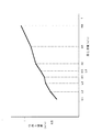
そして、図8の如く、車速に対する刈取搬送速度の比(刈取搬送速度/車速)である刈取搬送比と車速の関係を、仮想線で示す従来の一定値に対し、二次曲線となる実線で示されるように変化させるもので、車速が低速のときに刈取搬送比が大きく変化し、平均的な収穫作業の車速を基準として刈取搬送速度を設定しても、高速走行収穫作業時に比べて低速走行収穫作業時の刈取搬送速度の変化を車速に対して小さくして刈取搬送に必要な最低速度(主変速中立時の刈取速度=副変速1速の刈取速度)以上に維持されるように構成している。
【0016】
さらに、図1において、各センサ(43)〜(45)及び各スイッチ(47)〜(50)によりエンジン(14a)の回転、脱穀部(4)及び刈取部(8)の駆動を検出するもので、刈取部(8)の駆動速度が設定以上であるか否かを制御回路(46)で判断し、刈取部(8)が駆動されているときにだけ刈取変速モータ(32)を作動可能とし、該モータ(32)による制御動作が行われるように構成している。
【0017】
また増速及び減速用の手動スイッチ(53)(54)を前記制御回路(46)に接続させ、車速を検出するセンサ(41)(42)出力による自動制御動作と同様に、手動スイッチ(53)(54)の手動制御においても、刈取部(8)が駆動されているときにだけ刈取変速モータ(32)を作動できるように構成している。
【0018】
また刈取変速モータ(32)によって変更される刈取部(8)の刈取搬送速度の基準値を設定するセレクトスイッチ(55)を備え、該スイッチ(55)を前記制御回路(46)に接続させ、作物条件などに応じて刈取部(8)の刈取搬送速度を無段階に選択できるように構成している。
【0019】
上記から明らかなように、走行クローラ(2)を装設させる機台(3)上に脱穀部(4)を設け、刈刃及び穀稈搬送機構を備える刈取部(8)から刈取り穀稈を脱穀部(4)のフィードチェン(5)に供給させ、フィードチェン(5)によって挾持搬送する穀稈を脱穀部(4)の扱胴(6)によって脱粒すると共に、刈取部(8)に駆動力を入力させる刈取入力軸(25)及び刈取変速部材である刈取変速モータ(32)と、刈取部(8)の駆動を検出する刈取センサである刈取スイッチ(49)と、走行クローラ(2)の速度を検出する車速センサ(44)と、作物条件別に刈取変速データを記憶させる制御回路(46)と、作物条件を選択するセレクトスイッチ(55)を設けるコンバインにおいて、前記刈取変速モータ(32)によって切換える無段刈取変速機構(29)の伝動上手側に刈取駆動プーリ(23)を設けると共に、脱穀部(4)及び刈取部(8)の作動を脱穀センサである脱穀スイッチ(50)及び刈取スイッチ(49)が検出しているとき、車速センサ(44)と刈取速度センサ(45)の入力により、刈取部(8)速度の変更可否を判断し、刈取部(8)速度変更可のとき、刈取部(8)の穀稈搬送速度を自動的に変更させる。そして、刈取駆動プーリ(23)に懸架させるベルトのテンションローラを利用して簡単な機械式刈取クラッチを形成することにより、刈取部(8)に設ける刈刃または刈取り穀稈の搬送機構を刈取駆動プーリ(23)側のクラッチ切操作によって瞬時に停止させることが可能になり、前記ベルト(28)または刈取部(8)各部の異常駆動を防止し、しかも収穫作業状態下で、刈取部(8)速度変更可否を判断し、刈取部(8)の穀稈搬送速度が変更されるから、一定以上の移動速度で収穫作業を行っているとき以外での刈取部(8)速度変更を防止し、刈取部(8)穀稈搬送機構部での稈詰り等を阻止し、運転操作の簡略化並びに収穫作業能率の向上などを図る。
【0020】
本実施例は上記の如く構成しており、エンジン(14a)を作動させ、刈取及び脱穀クラッチレバー(19)(20)を入操作し、圃場内を移動して収穫作業を行う場合、図10の如く、エンジン回転センサ(43)により回転の有無が検出され、エンジン(14a)の油圧及び充電作用、並びに前記各レバー(19)(20)の入動作が各スイッチ(47)〜(50)によって検出されると共に、車速センサ(44)によってコンバインの移動が確認され、また刈取速度センサ(45)によって刈取部(8)の作動が確認され、刈取部(8)の駆動速度を変更する刈取変速が可能であることを制御回路(46)で判断する。
【0021】
そして、主変速センサ(41)から主変速位置を、また副変速センサ(42)から副変速位置を入力して車速の演算が行われると共に、刈取変速センサ(40)から刈取変速位置を入力し、図9の如く、車速に基づいて刈取搬送速度が演算されるもので、副変速が低速(L1、L2、L3、L4)のときと、高速(H1、H2、H3、H4)のときとで主変速(前進1、2、3、4)との組合せにより、引起し速度が算出され、このデータを予め記憶させている前記制御回路(46)の増速又は減速信号出力により刈取変速モータ(32)が正転又は逆転作動し、扇形ギヤ(34)及び無段変速カム(30)などを介して刈取変速機構(29)を作動制御し、車速に対し刈取搬送速度を連動して変更させ乍ら収穫作業を行うものである。
【0022】
【発明の効果】
以上実施例から明らかなように本発明は、刈取駆動プーリ(23)に懸架させるベルトのテンションローラを利用して簡単な機械式刈取クラッチを形成することにより、刈取部(8)に設ける刈刃または刈取り穀稈の搬送機構を刈取駆動プーリ(23)側のクラッチ切操作によって瞬時に停止させることができ、前記ベルト(28)または刈取部(8)各部の異常駆動を防止でき、しかも収穫作業状態下で、刈取部(8)速度変更可否を判断し、刈取部(8)の穀稈搬送速度が変更されるから、一定以上の移動速度で収穫作業を行っているとき以外での刈取部(8)速度変更を容易に防止でき、刈取部(8)穀稈搬送機構部での稈詰り等を容易に阻止でき、運転操作の簡略化並びに収穫作業能率の向上などを容易に図ることができるものである。
そして、特に、制御回路(46)にエンジン回転センサ(43)と、バッテリ充電作用が適正に行われていることを検出するスイッチ(48)とを接続するとともに、刈取部(8)の作動を刈取センサが検出しているとき、車速センサ(44)と刈取速度センサ(45)の入力により、刈取部(8)速度の変更可否を判断し、刈取部(8)速度変更可のとき、刈取部(8)の穀稈搬送速度を自動的に変更させるように構成するとともに、
前記エンジン回転センサ(43)によりエンジンの回転が検出され、かつ、充電作用が検出された後に、刈取速度センサ(45)によって刈取部(8)の作動が確認され、刈取部(8)の駆動速度を変更する刈取変速が可能であることを制御回路(46)で判断するように構成したので、刈取部(8)速度変更を確実に行え、刈取部(8)各部の異常駆動を防止でき信頼性の高い刈取速度の制御を実施することができる。
【図面の簡単な説明】
【図1】本発明の一実施例を示す制御回路図。
【図2】コンバインの側面図。
【図3】同平面図。
【図4】変速機構の説明図。
【図5】同説明図。
【図6】変速操作部材の説明図。
【図7】同説明図。
【図8】変速出力線図。
【図9】引起搬送出力線図。
【図10】フローチャート。
【符号の説明】
(2) 走行クローラ
(3) 機台
(4) 脱穀部
(5) フィードチェン
(6) 扱胴
(8) 刈取部
(23) 刈取駆動プーリ
(25) 刈取入力軸
(29) 無段刈取変速機構
(32) 刈取変速モータ(刈取変速部材)
(44) 車速センサ
(45) 刈取速度センサ
(46) 制御回路
(50) 脱穀スイッチ(脱穀センサ)
(55) セレクトスイッチ[0001]
TECHNICAL FIELD OF THE INVENTION
The present invention relates to a combine harvester that cuts a grain stalk at a cutting section while moving by driving a traveling crawler and threshing at a threshing section to perform a harvesting operation.
[0002]
[Prior art]
Conventionally, as disclosed in Japanese Patent Application Laid-Open No. 56-5013, a continuously variable harvesting speed is provided in which a threshing unit and a harvesting unit for continuously performing a harvesting operation are provided, and a driving speed of a harvesting unit for transmitting power of an engine is continuously changed. There is a technique for providing a mechanism.
[0003]
[Problems to be solved by the invention]
In the prior art, the cutting speed change lever is connected to the running speed change lever, and the stepless cutting speed change mechanism is switched by operating the cutting speed change lever by manual operation of the running speed change lever. When changing the gear ratio of the cutting speed, it is necessary to perform an adjustment operation such as changing the fulcrum position of the cutting speed lever or changing the length of the speed changing rod connected to the cutting speed lever. Since the above-mentioned adjustment work is performed, there is a problem that it is not easy to improve the handling operability and the efficiency of the harvesting work.
[0004]
Further, as disclosed in Japanese Utility Model Laid-Open Publication No. Sho 62-178841, a continuously variable transmission mechanism formed of a continuously variable transmission pulley and a continuously variable transmission belt is provided to transmit the engine driving force to the reaping unit, and the continuously variable transmission mechanism is operated to perform a speed change operation. There is also a technique of providing a mowing speed change motor that causes the mowing speed to be changed. However, in the prior art, a tension pulley is pressed against the continuously variable transmission belt, a cutting speed lever is connected to an arm on which the pulley is mounted via a wire, and a cutting speed motor is connected via a spiral rod between the levers. Therefore, the operation of the mowing speed change motor is prohibited by stopping the engine, but even when the engine is stopped, the tension pulley is operated by the operation of the mowing speed change lever and the continuously variable speed pulley is stopped. Since the speed change of the continuously variable transmission belt is performed, there is a problem that it is not easy to prevent erroneous operation that damages the continuously variable transmission mechanism and to improve the durability of the continuously variable transmission belt.
[0005]
Further, as disclosed in Japanese Utility Model Application Laid-Open No. 59-163343 and Japanese Utility Model Application Laid-Open No. 60-44539, there is a technology for detecting a moving speed of a harvesting operation and automatically changing a driving speed of a reel for scraping an uncut culm. However, since the driving speed of the mowing blade and the grain culm transport mechanism is substantially constant, even if the threshing unit moves at high speed during low-load work, low-load operation is performed until the culm of the mowing unit reaches the threshing unit. During this time, the moving speed is further increased by the operator's erroneous operation, the threshing unit is likely to be overloaded, and the threshing unit is supplied to the threshing unit even if the moving speed is reduced during high load work. High-load operation is continued until the number of grain culms to be reduced decreases.During this time, the moving speed is further reduced due to misidentification by the operator, the threshing unit becomes a low-load operation, the work efficiency is likely to decrease, and the threshing load is reduced. Easy moving speed Proper maintenance linking moiety, there is a problem that not aim to facilitate and improve the simplicity and harvesting efficiency of the driving operation.
[0006]
[Means for Solving the Problems]
According to the present invention, however, a threshing unit (4) is provided on a machine (3) on which a traveling crawler (2) is mounted, and threshing of a harvested culm from a reaping unit (8) including a cutting blade and a culm transport mechanism. The grain is fed to the feed chain (5) of the section (4), the grain culm conveyed by the feed chain (5) is threshed by the handling cylinder (6) of the threshing section (4), and the driving force is applied to the cutting section (8). A cutting input shaft (25) and a cutting speed change member (32) for inputting a signal, a cutting sensor (49) for detecting the drive of the cutting unit (8), and a vehicle speed sensor (44) for detecting the speed of the traveling crawler (2). And a control circuit (46) for storing mowing shift data for each crop condition and a select switch (55) for selecting a crop condition.
A cutting drive pulley (23) is provided on the transmission side of the continuously variable cutting speed change mechanism (29), and the control circuit (46) confirms that the engine rotation sensor (43) and the battery charging operation are properly performed. A switch (48) for detection is connected, and when the cutting sensor detects the operation of the cutting unit (8), the cutting unit (8) is input by the vehicle speed sensor (44) and the cutting speed sensor (45). It is configured to determine whether the speed can be changed, and to automatically change the grain culm transport speed of the cutting unit (8) when the cutting unit (8) can change the speed.
After the rotation of the engine is detected by the engine rotation sensor (43) and the charging action is detected, the operation of the cutting unit (8) is confirmed by the cutting speed sensor (45), and the driving of the cutting unit (8) is performed. The control circuit (46) determines that a mowing shift for changing the speed is possible ,
By forming a simple mechanical cutting clutch using the tension roller of the belt suspended on the cutting drive pulley, the transfer mechanism of the cutting blade or cutting grain culm provided in the cutting section can be instantaneously operated by the clutch disengagement operation on the cutting drive pulley side. It can be stopped to prevent abnormal driving of the belt or each part of the mowing part, and under the harvesting condition, it is determined whether the mowing part speed can be changed, and the grain culm transport speed of the mowing part is changed, so that it is not less than a certain value. It is possible to easily prevent a change in the speed of the harvesting unit except when harvesting at the moving speed of the cultivation unit, easily prevent culm clogging in the harvesting unit's grain culm transport mechanism, simplify the operation operation and harvest. It is possible to easily improve the work efficiency and the like.
[0007]
BEST MODE FOR CARRYING OUT THE INVENTION
Hereinafter, embodiments of the present invention will be described in detail with reference to the drawings. FIG. 1 is a control circuit diagram, FIG. 2 is a side view of the combine, and FIG. 3 is a plan view thereof. In the figure, (1) is a track frame on which a traveling crawler (2) is mounted, and (3) is the track frame ( 1) A machine erected above, (4) a threshing unit which stretches a feed chain (5) to the left and incorporates a handling cylinder (6) and a processing cylinder (7), and (8) a cutting blade and A harvesting unit including a grain culm transport mechanism and the like; (9) a straw processing unit facing the end of a straw chain (10); (11) a driver's cab including a driver's seat (12) and a driving operation unit (13); (14) is an engine room in which an engine (14a) is provided, and (15) is a grain tank for storing grains from the threshing unit (4), which is configured to continuously perform cutting and threshing operations. I have.
[0008]
Also, in the figure, (16) is a raising / lowering and steering lever for performing a raising / lowering operation of the reaper (8) and a steering operation by left and right side clutch control, (17) is a traveling main transmission lever, and (18) is a sub transmission. A lever, (19) is a reaping clutch lever, and (20) is a threshing clutch lever.
[0009]
Further, as shown in FIGS. 4 and 5, a transmission shaft (22) is supported on a support shaft (3a) of the machine base (3) via a bearing body (21) to transmit the driving force of the engine (14a). A cutting drive pulley (23) is provided on the transmission shaft (22), and a cutting input shaft (25) is supported by a cutting drive case (24) of the cutting unit (8). A cutting speed change mechanism (29) including a pair of split pulleys (26) (27) and a belt (28) is provided, and the split shaft (26) is mounted on the transmission shaft (22) and the cutting input shaft (25). (27), and a continuously variable transmission cam (30) is provided on the split pulley (26) of the transmission shaft (22).
[0010]
As shown in FIGS. 6 and 7, a mowing speed change motor (32), which is a speed change operation member, is provided inside an inside box (31) of the operation operation portion (13), and an output gear (33) of the motor (32) is provided. ) And a continuously variable cam (30) via a transmission rod (35) (36), a transmission arm (37) (38) and a transmission shaft (39). The continuously variable cam (30) is controlled to operate via a sector gear (34) by forward / reverse rotation control of the motor (32), and the split pulley (26) Is changed so that the output rotation speed of the belt (28) is changed, and the mowing transport speed of the mowing section (8) is continuously variable.
[0011]
In addition, a potentiometer type cutting speed change sensor (40) for detecting a rotation angle of the gear (34) in conjunction with the sector gear (34) is provided, and the cutting speed position by the motor (32) is set by the sensor (40). It is configured to detect.
[0012]
Further, as shown in FIG. 1, a potentiometer-type main shift sensor (41) for detecting the main shift position in conjunction with the main shift lever (17) and a sub-shift position in conjunction with the auxiliary shift lever (18). A changeover switch type auxiliary speed sensor (42), a pickup type engine rotation sensor (43) for detecting the rotation speed of the engine (14a), and a pickup type vehicle speed sensor (44) for detecting the rotation speed of the traveling crawler (2). And a pickup type cutting speed sensor (45) for detecting the driving speed of the cutting blade of the cutting unit (8) and the transport mechanism.
[0013]
A cutting / transporting speed control circuit (46) composed of a microcomputer is provided, and the sensors (40) to (45) are input-connected to the control circuit (46), and the hydraulic pressure of the engine (14a) is adjusted to an appropriate level. (47), a switch (48) for detecting that the battery charging operation of the engine (14a) is being performed properly, a cutting and threshing clutch lever (19) (20). ) Are provided with switches (49) and (50) for detecting a clutch engagement operation, and the switches (47) to (50) are connected to the control circuit (46).
[0014]
Also, the cutting speed change motor (32) is connected to the control circuit (46) via a speed increasing circuit (51) and a deceleration circuit (52), based on the vehicle speed detected by each sensor (41) (42). An operation of the mowing speed change motor (32) is controlled to change the mowing transport speed of the mowing part (8).
[0015]
Then, as shown in FIG. 8, the relationship between the cutting transfer ratio, which is the ratio of the cutting transfer speed to the vehicle speed (cutting transfer speed / vehicle speed), and the vehicle speed is represented by a solid line that is a quadratic curve with respect to a conventional constant value indicated by a virtual line. As shown in the figure, when the vehicle speed is low, the harvesting conveyance ratio greatly changes, and even when the harvesting conveyance speed is set based on the average harvesting vehicle speed, the harvesting conveyance speed is lower than that during high-speed traveling harvesting work. A configuration in which the change in the reaping conveyance speed during the traveling harvesting operation is made smaller than the vehicle speed, and is maintained at a speed higher than the minimum speed required for reaping conveyance (the reaping speed when the main transmission is neutral = the reaping speed at the first subtransmission). are doing.
[0016]
In FIG. 1, the sensors (43) to (45) and the switches (47) to (50) detect the rotation of the engine (14a) and the driving of the threshing unit (4) and the cutting unit (8). Then, the control circuit (46) determines whether the driving speed of the reaping unit (8) is higher than a set speed, and the reaping transmission motor (32) can be operated only when the reaping unit (8) is driven. The control operation by the motor (32) is performed.
[0017]
Further, manual switches (53) and (54) for speed increase and deceleration are connected to the control circuit (46), and the manual switches (53) are used similarly to the automatic control operation based on the outputs of the sensors (41) and (42) for detecting the vehicle speed. Also in the manual control of (54), the mowing speed change motor (32) can be operated only when the mowing part (8) is driven.
[0018]
And a select switch (55) for setting a reference value of a cutting transfer speed of the cutting unit (8) changed by the cutting speed change motor (32). The switch (55) is connected to the control circuit (46). The reaping unit (8) is configured so that the reaping transport speed can be selected steplessly according to crop conditions and the like.
[0019]
As is apparent from the above description, a threshing unit (4) is provided on a machine base (3) on which a traveling crawler (2) is mounted, and a harvested culm is harvested from a reaping unit (8) including a cutting blade and a cereal culm transport mechanism. The feed chain (5) of the threshing unit (4) is fed to the feed chain (5), and the grain culm conveyed by the feed chain (5) is threshed by the handling cylinder (6) of the threshing unit (4) and driven to the cutting unit (8). A cutting input shaft (25) for inputting force and a cutting transmission motor (32) as a cutting transmission member, a cutting switch (49) as a cutting sensor for detecting driving of the cutting section (8), and a traveling crawler (2). A harvesting speed change motor (32) in a combine provided with a vehicle speed sensor (44) for detecting the speed of the vehicle, a control circuit (46) for storing cutting speed data for each crop condition, and a select switch (55) for selecting a crop condition. By A cutting drive pulley (23) is provided on the transmission side of the continuously variable cutting transmission mechanism (29) to be switched, and the operation of the threshing unit (4) and the cutting unit (8) is controlled by a threshing switch (50) and a cutting switch serving as a threshing sensor. When (49) is detecting, it is determined whether the speed of the reaper (8) can be changed based on the input of the vehicle speed sensor (44) and the reaping speed sensor (45). Automatically change the conveying speed of the grain culm of the cutting unit (8). Then, a simple mechanical cutting clutch is formed by using a tension roller of a belt suspended on the cutting drive pulley (23), so that a cutting blade provided in the cutting section (8) or a mechanism for transporting the cut grain culm is driven by the cutting drive. The pulling (23) side can be instantaneously stopped by a clutch disengagement operation, thereby preventing abnormal driving of the belt (28) or the respective sections of the reaping section (8). ) Judging whether the speed change is possible or not and changing the speed of transporting the grain culm of the reaping unit (8), preventing the reaping unit (8) from changing the speed except when the harvesting operation is being performed at a moving speed exceeding a certain level. The cutting section (8) prevents culm clogging and the like in the grain culm transport mechanism section, simplifies the driving operation, improves the harvesting work efficiency, and the like.
[0020]
This embodiment is configured as described above. When the engine (14a) is operated, the cutting and threshing clutch levers (19) and (20) are turned on, and the user moves in the field to perform the harvesting operation, FIG. As described above, the presence or absence of rotation is detected by the engine rotation sensor (43), and the oil pressure and charging operation of the engine (14a) and the on / off operation of the levers (19) and (20) are determined by the switches (47) to (50). , The movement of the combine is confirmed by the vehicle speed sensor (44), the operation of the cutting unit (8) is confirmed by the cutting speed sensor (45), and the cutting speed for changing the drive speed of the cutting unit (8) is determined. The control circuit (46) determines that the shift is possible.
[0021]
The vehicle speed is calculated by inputting the main shift position from the main shift sensor (41) and the sub-shift position from the sub-shift sensor (42), and the reaping shift position is input from the reaping shift sensor (40). As shown in FIG. 9, the mowing transport speed is calculated based on the vehicle speed, and when the sub speed is low (L1, L2, L3, L4) and when the sub speed is high (H1, H2, H3, H4). In accordance with the combination with the main speed change (forward 1, 2, 3, 4), the wake-up speed is calculated, and this data is stored in advance, and the mowing speed change motor is output by the speed increase or deceleration signal output of the control circuit (46). (32) rotates forward or reverse to control the operation of the mowing transmission mechanism (29) via the sector gear (34) and the continuously variable cam (30), etc., and changes the mowing transport speed in conjunction with the vehicle speed. The harvesting work is performed while doing so.
[0022]
【The invention's effect】
As is apparent from the above embodiment, the present invention provides a cutting blade provided in the cutting section (8) by forming a simple mechanical cutting clutch using a tension roller of a belt suspended on the cutting drive pulley (23). Alternatively, the transport mechanism of the cutting grain culm can be instantaneously stopped by the clutch disengagement operation on the cutting drive pulley (23) side, and abnormal driving of the belt (28) or the cutting section (8) can be prevented, and the harvesting operation can be performed. Under the condition, it is determined whether or not the speed of the reaping unit (8) can be changed, and the culm conveying speed of the reaping unit (8) is changed. (8) The change in speed can be easily prevented, and the cutting section (8) The clogging of the culm transport mechanism can be easily prevented, thereby simplifying the driving operation and improving the efficiency of the harvesting operation. Can do .
In particular, the control circuit (46) is connected to the engine rotation sensor (43) and the switch (48) for detecting that the battery charging operation is properly performed, and the operation of the reaper (8) is controlled. When the reaping sensor is detecting, it is determined whether or not the speed of the reaping unit (8) can be changed based on the input of the vehicle speed sensor (44) and the reaping speed sensor (45). While configuring so that the grain stalk transport speed of the part (8) is automatically changed,
After the rotation of the engine is detected by the engine rotation sensor (43) and the charging action is detected, the operation of the cutting unit (8) is confirmed by the cutting speed sensor (45), and the driving of the cutting unit (8) is performed. Since the control circuit (46) determines that the reaping shift for changing the speed is possible, the reaping unit (8) can surely change the speed and prevent abnormal driving of each unit of the reaping unit (8). Reliable control of the cutting speed can be performed.
[Brief description of the drawings]
FIG. 1 is a control circuit diagram showing one embodiment of the present invention.
FIG. 2 is a side view of the combine.
FIG. 3 is a plan view of the same.
FIG. 4 is an explanatory diagram of a transmission mechanism.
FIG. 5 is an explanatory view of the same.
FIG. 6 is an explanatory view of a speed change operation member.
FIG. 7 is an explanatory view of the same.
FIG. 8 is a shift output diagram.
FIG. 9 is a diagram showing a triggered conveyance output diagram.
FIG. 10 is a flowchart.
[Explanation of symbols]
(2) Traveling crawler (3) Machine stand (4) Threshing unit (5) Feed chain (6) Handling cylinder (8) Cutting unit (23) Cutting drive pulley (25) Cutting input shaft (29) Stepless cutting transmission mechanism (32) Mowing transmission motor (reaching transmission member)
(44) Vehicle speed sensor (45) Cutting speed sensor (46) Control circuit (50) Threshing switch (threshing sensor)
(55) Select switch
Claims (1)
無段刈取変速機構(29)の伝動上手側に刈取駆動プーリ(23)を設けると共に、
前記制御回路(46)にエンジン回転センサ(43)と、バッテリ充電作用が適正に行われていることを検出するスイッチ(48)とを接続するとともに、刈取部(8)の作動を刈取センサが検出しているとき、車速センサ(44)と刈取速度センサ(45)の入力により、刈取部(8)速度の変更可否を判断し、刈取部(8)速度変更可のとき、刈取部(8)の穀稈搬送速度を自動的に変更させるように構成するとともに、
前記エンジン回転センサ(43)によりエンジンの回転が検出され、かつ、充電作用が検出された後に、刈取速度センサ(45)によって刈取部(8)の作動が確認され、刈取部(8)の駆動速度を変更する刈取変速が可能であることを制御回路(46)で判断するように構成したことを特徴とするコンバイン。 A threshing unit (4) is provided on a machine (3) on which a traveling crawler (2) is mounted, and the harvesting culm is fed from the reaping unit (8) having a cutting blade and a culm transport mechanism to the threshing unit (4). A cutting input shaft for feeding the culm to be fed to the chain (5) and nipping and transporting the culm by the feed chain (5) with the handling cylinder (6) of the threshing unit (4) and for inputting a driving force to the cutting unit (8). (25) and a cutting transmission member (32), a cutting sensor (49) for detecting the drive of the cutting unit (8), a vehicle speed sensor (44) for detecting the speed of the traveling crawler (2), and cutting for each crop condition. In a combine provided with a control circuit (46) for storing shift data and a select switch (55) for selecting crop conditions,
A cutting drive pulley (23) is provided on the transmission upper side of the continuously variable cutting transmission mechanism (29),
The control circuit (46) is connected to an engine rotation sensor (43) and a switch (48) for detecting that the battery charging operation is being performed properly. When the speed is detected, it is determined whether or not the speed of the reaping unit (8) can be changed based on the input of the vehicle speed sensor (44) and the reaping speed sensor (45). ) And automatically change the culm conveyance speed
After the rotation of the engine is detected by the engine rotation sensor (43) and the charging action is detected, the operation of the cutting unit (8) is confirmed by the cutting speed sensor (45), and the driving of the cutting unit (8) is performed. A combine wherein the control circuit (46) determines that a mowing shift for changing the speed is possible.
Priority Applications (1)
| Application Number | Priority Date | Filing Date | Title |
|---|---|---|---|
| JP2000372323A JP3558594B2 (en) | 2000-12-07 | 2000-12-07 | Combine |
Applications Claiming Priority (1)
| Application Number | Priority Date | Filing Date | Title |
|---|---|---|---|
| JP2000372323A JP3558594B2 (en) | 2000-12-07 | 2000-12-07 | Combine |
Related Parent Applications (1)
| Application Number | Title | Priority Date | Filing Date |
|---|---|---|---|
| JP25657499A Division JP3252260B2 (en) | 1999-09-10 | 1999-09-10 | Combine |
Publications (2)
| Publication Number | Publication Date |
|---|---|
| JP2001186810A JP2001186810A (en) | 2001-07-10 |
| JP3558594B2 true JP3558594B2 (en) | 2004-08-25 |
Family
ID=18841889
Family Applications (1)
| Application Number | Title | Priority Date | Filing Date |
|---|---|---|---|
| JP2000372323A Expired - Lifetime JP3558594B2 (en) | 2000-12-07 | 2000-12-07 | Combine |
Country Status (1)
| Country | Link |
|---|---|
| JP (1) | JP3558594B2 (en) |
Families Citing this family (2)
| Publication number | Priority date | Publication date | Assignee | Title |
|---|---|---|---|---|
| JP4667133B2 (en) * | 2005-06-20 | 2011-04-06 | 三菱農機株式会社 | Sector gear rotation angle detection device |
| CN112005707A (en) * | 2020-08-18 | 2020-12-01 | 安徽聚力创新项目管理有限公司 | Motor drive-based automatic variable speed control system and device for harvester |
-
2000
- 2000-12-07 JP JP2000372323A patent/JP3558594B2/en not_active Expired - Lifetime
Also Published As
| Publication number | Publication date |
|---|---|
| JP2001186810A (en) | 2001-07-10 |
Similar Documents
| Publication | Publication Date | Title |
|---|---|---|
| JP3013036B2 (en) | Combine | |
| JP2009017794A (en) | Combine harvester | |
| JP4897744B2 (en) | Combine | |
| CN110603949A (en) | Harvester and combine harvester | |
| JP3692645B2 (en) | Harvesting equipment such as combine | |
| JPH06343335A (en) | Combine feed chain controller | |
| JP2935016B2 (en) | Combine | |
| JP2736884B2 (en) | Harvester vehicle speed control device | |
| JPH10164958A (en) | Speed control device of pre-cutting device in combine harvester | |
| JP2613426B2 (en) | Harvester | |
| JP2532858Y2 (en) | Harvester | |
| JP3252260B2 (en) | Combine | |
| JP4507800B2 (en) | Combine | |
| JPH078079A (en) | Combine | |
| JP2001186810A (en) | Combine | |
| JP2004097052A (en) | Drive control structure of combine | |
| JPH1052148A (en) | Combine | |
| JP2707090B2 (en) | Combine speed controller | |
| JPH1028455A (en) | Combine | |
| JP4524531B2 (en) | Combine | |
| JPH0767441A (en) | Combine speed control device | |
| JP2788571B2 (en) | Combine handling depth control device | |
| JPH09262022A (en) | Vehicle speed control device for agricultural vehicles | |
| JP3138879B2 (en) | Combine | |
| JPH0923730A (en) | Normal type combine |
Legal Events
| Date | Code | Title | Description |
|---|---|---|---|
| A521 | Written amendment |
Free format text: JAPANESE INTERMEDIATE CODE: A523 Effective date: 20040223 |
|
| A61 | First payment of annual fees (during grant procedure) |
Free format text: JAPANESE INTERMEDIATE CODE: A61 Effective date: 20040518 |
|
| EXPY | Cancellation because of completion of term | ||
| FPAY | Renewal fee payment (event date is renewal date of database) |
Free format text: PAYMENT UNTIL: 20080528 Year of fee payment: 4 |