JP3556589B2 - Position and orientation recognition device - Google Patents
Position and orientation recognition device Download PDFInfo
- Publication number
- JP3556589B2 JP3556589B2 JP2000285526A JP2000285526A JP3556589B2 JP 3556589 B2 JP3556589 B2 JP 3556589B2 JP 2000285526 A JP2000285526 A JP 2000285526A JP 2000285526 A JP2000285526 A JP 2000285526A JP 3556589 B2 JP3556589 B2 JP 3556589B2
- Authority
- JP
- Japan
- Prior art keywords
- sensor
- dimensional
- sensor means
- recognition device
- posture
- Prior art date
- Legal status (The legal status is an assumption and is not a legal conclusion. Google has not performed a legal analysis and makes no representation as to the accuracy of the status listed.)
- Expired - Fee Related
Links
Images


Classifications
-
- B—PERFORMING OPERATIONS; TRANSPORTING
- B25—HAND TOOLS; PORTABLE POWER-DRIVEN TOOLS; MANIPULATORS
- B25J—MANIPULATORS; CHAMBERS PROVIDED WITH MANIPULATION DEVICES
- B25J9/00—Programme-controlled manipulators
- B25J9/16—Programme controls
- B25J9/1694—Programme controls characterised by use of sensors other than normal servo-feedback from position, speed or acceleration sensors, perception control, multi-sensor controlled systems, sensor fusion
- B25J9/1697—Vision controlled systems
-
- G—PHYSICS
- G05—CONTROLLING; REGULATING
- G05B—CONTROL OR REGULATING SYSTEMS IN GENERAL; FUNCTIONAL ELEMENTS OF SUCH SYSTEMS; MONITORING OR TESTING ARRANGEMENTS FOR SUCH SYSTEMS OR ELEMENTS
- G05B2219/00—Program-control systems
- G05B2219/30—Nc systems
- G05B2219/39—Robotics, robotics to robotics hand
- G05B2219/39393—Camera detects projected image, compare with reference image, position end effector
-
- G—PHYSICS
- G05—CONTROLLING; REGULATING
- G05B—CONTROL OR REGULATING SYSTEMS IN GENERAL; FUNCTIONAL ELEMENTS OF SUCH SYSTEMS; MONITORING OR TESTING ARRANGEMENTS FOR SUCH SYSTEMS OR ELEMENTS
- G05B2219/00—Program-control systems
- G05B2219/30—Nc systems
- G05B2219/40—Robotics, robotics mapping to robotics vision
- G05B2219/40053—Pick 3-D object from pile of objects
-
- G—PHYSICS
- G05—CONTROLLING; REGULATING
- G05B—CONTROL OR REGULATING SYSTEMS IN GENERAL; FUNCTIONAL ELEMENTS OF SUCH SYSTEMS; MONITORING OR TESTING ARRANGEMENTS FOR SUCH SYSTEMS OR ELEMENTS
- G05B2219/00—Program-control systems
- G05B2219/30—Nc systems
- G05B2219/40—Robotics, robotics mapping to robotics vision
- G05B2219/40613—Camera, laser scanner on end effector, hand eye manipulator, local
Description
【0001】
【発明の属する技術分野】
本願発明は、種々のファクトリオートメーションに適用可能な位置姿勢認識装置に関し、更に詳しく言えば、2次元情報を取得するセンサと3次元情報を取得するセンサとを適宜併用した複合的な位置姿勢計測装置に関する。
【0002】
【従来の技術】
製造ラインにおける組み立て作業、加工作業等においては、各種のセンサを用いて種々の対象物の位置や形状を検出することが頻繁に行なわれる。通常、対象物の位置を大局的に計測するには2次元画像を取得出来るセンサが有効である。例えば、CCDカメラを用いる場合、光学系(レンズ)を適当に選択することによって比較的広い視野を持たせることが容易である。これに対して、局所的な位置や形状を3次元的に計測するにはレーザセンサが有効である。
【0003】
レーザセンサはロボットの手先部に搭載が容易であり、レーザセンサの出力をロボットコントローラに取り入れるようにした場合、至近距離から対象物へレーザビームを投射して対象物の細部の位置、形状等を精密且つリアルタイムに計測出来る等の特徴を有している。そのため、レーザセンサはロボットシステム等に頻繁に装備され、例えば、アーク溶接、シーリング、計測などの分野で広く利用されている。
【0004】
レーザセンサは、レーザ光をスポット光ビームで走査するものと、スリット光を投射するものとがある。いずれの型のレーザセンサを用いた場合も、スポット光ビームあるいはスリット光を対象物面上に確実に投射しなければならない。対象物がある程度の精度で一定位置に位置決めされていれば、該一定位置の近傍位置をロボットにアプローチ位置として予め教示しておくことで、スポット光ビームあるいはスリット光を対象物面上に投射される状態を迅速に現出することは容易である。
【0005】
しかし、アプリケーションによっては、対象物の位置決めが行なわれず未知の場合や、位置決めの精度に信頼性がない場合が少なくない。そのような場合には、ロボットなどの移動手段を用いて移動させながらレーザセンサのスポット光ビームあるいはスリット光をプローブに用いて対象物をサーチし、対象物を発見しなければ、レーザセンサによるメインの計測(例えば、形状測定)を開始することが出来ない。
【0006】
レーザセンサは元来広範囲の測定には不向きであるから、対象物サーチとそれに続く対象物へのアプローチ動作に時間を要し、場合によっては、対象物を確実にサーチすること自体が困難な場合もあり得る。
【0007】
【発明が解決しようとする課題】
そこで、本願発明の目的は、対象物の位置や姿勢が未知であっても、例えばレーザセンサのように比較的狭い領域のセンシングしか出来ないセンサの使用を可能にし、しかも、同センサによる対象物の2次元情報または3次元情報の認識を適正な位置と姿勢で確実に行えるようにした認識装置を提供することにある。
【0008】
【課題を解決するための手段】
本願発明に従った認識装置は、先ず前提構成として、対象領域内の2次元情報を取得する第1のセンサ手段と、同対象領域と比較して相対的に狭い領域内の対象領域内の情報を取得する第2のセンサ手段とを含む。ここで、第2のセンサ手段が取得する情報は、2次元情報あるいは3次元情報である。
【0009】
そして、本願発明の認識装置は、遠近が未知の対象物を認識するものであって、第1のセンサ手段により取得された対象物の情報を含む2次元情報と、第1のセンサ手段の位置及び姿勢とに基づいて、同対象物と第1のセンサ手段とを結ぶ3次元空間上の直線を求める手段と、第2のセンサ手段による同対象物の認識が可能になる該第2のセンサ手段の位置及び姿勢を前記直線から求める手段と、第2のセンサ手段を前記求めた位置及び姿勢に移動させる手段とを備える。
【0010】
そして、本願発明の認識装置は、この移動手段により第2のセンサ手段を上記の求めた位置及び姿勢に移動させた後に、第2のセンサ手段により同対象物の2次元情報または3次元的な位置姿勢情報を取得することにより、同対象物の2次元情報または3次元情報を認識する。
【0011】
第2のセンサ手段は2次元情報を取得するものであり、且つ、第1のセンサ手段が第2のセンサ手段を兼ねていても良い。また、第2のセンサ手段は、光照射手段と受光手段を備え、3次元的な位置姿勢測定を行なう機能を有していても良い。
【0012】
その場合、この受光手段を2次元情報を取得する2次元センサとしても良く、更に、第2のセンサ手段に第1のセンサ手段を兼ねさせることも可能である。
【0013】
第2のセンサ手段が光照射手段と受光手段を備え、3次元的な位置姿勢測定を行なう機能を有していいる場合、第2のセンサ手段が対象物の認識を行なう位置及び姿勢は、光照射手段の光照射方向が上記の求められた直線(対象物と第1のセンサ手段とを結ぶ直線)に一致すように決定されて良く、また、受光手段の光軸方向が同直線に一致するように決定されても良い。
【0014】
以上のいずれのケースにあっても、上記の3次元空間上の直線を求める手段、あるいは、第2のセンサ手段の位置及び姿勢を求める手段は、産業用ロボットのロボットコントローラに設けられていて良い。また、第2のセンサ手段を認識を行なう適所として求められた位置及び姿勢に移動させる手段として、産業用ロボットを用いることが出来る。
【0015】
本願発明の重要なポイントは、比較的広域内で2次元情報を取得出来る第1のセンサ手段で対象物を先ず見付け、その際に第1のセンサ手段と対象物とを結ぶ空間(現実の3次元空間)上の「直線」を求め、この「求められた直線」を、比較的狭い領域内での2次元情報または3次元情報を取得するに適した第2のセンサ手段の「対象物の認識(観測)に適した位置と姿勢」を定めるために利用した点にある。
【0016】
具体的な手順に即して言えば、先ず、第1のセンサで対象領域の2次元画像を取得し、同2次元画像を処理して対象物を2次元画像上で見つけ出し、2次元画像上での対象物の位置を検出する。ここで、「対象領域」は、対象物が存在する可能性があると考えられる範囲をカバーし得る領域のことである。
【0017】
この段階で判ることは、対象物の(現実の3次元)空間上の位置が第1のセンサのカメラが同対象物を捉えている「視線」上にあることである。即ち、対象物の遠近は未知である。この「視線」は、周知のように、カメラレンズのレンズ中心と結像面上の同対象物の結像位置とを結ぶ直線として、第1のセンサのカメラキャリブレーションで得られれたデータから決定出来る。
【0018】
即ち、キャリブレーションによって得られるデータから、「結像面上の同対象物の結像位置」乃至「画像上の対象物の位置」と、「視線の位置と方向」との関係を知ることが出来る。
【0019】
一般的に言えば、画像空間(2次元)上の位置(u、v)が判れば、同位置を通る視線(直線)が判る。この視線(直線)が表わす方程式は「視線方程式」とも呼ばれる。
【0020】
そこで、この視線を「第1のセンサと対象物を結ぶ直線」として利用出来る。なお、より厳密に言えば、「対象物の位置」は、「対象物上のある点(代表点という)の位置」の意味であり、「第1のセンサと対象物を結ぶ直線」とは、「第1のセンサと対象物上の代表点を結ぶ直線」のことである。
【0021】
さて、このようにして得られる「第1のセンサと対象物を結ぶ直線」は、第2のセンサを用いて行なうより詳細な認識(例えば、対象物のより正確な位置、姿勢、形状、寸法など)に適した位置と姿勢を定めるにあたって有効利用される。何故ならば、対象物は間違いなく求められた「空間上の直線」上に存在するのであるから、同直線上あるいはその近傍に第2のセンサを移動させ、同直線と整合する方位に第2のセンサの視野を向けるような姿勢をとれば、対象物を確実にとらえることが出来る。
【0022】
例えば、第2のセンサが光照射手段と受光手段を備え、3次元的な位置姿勢測定を行なう機能を有していれば、光照射の方向あるいは受光手段の光軸の方向を基準にして第2のセンサの姿勢を決めれば良い。
【0023】
【発明の実施の形態】
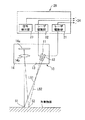
図1は、本願発明の1つの実施形態に係る3次元位置姿勢認識システムの全体配置の概要を説明する図である。一例として、システムはロボット(産業用ロボット;以下同じ)によるワークのハンドリング(ピックアップと搬送)に適用されている。ここで、ワークは複数個がそれぞれ位置や姿勢がバラバラな状態にある。ハンドリング作業をこのような状態から開始するに際して、本システムはその特徴を発揮する。
【0024】
同図に示したように、システム全体は、ロボットコントローラ1、画像処理装置2、レーザセンサ(本体部。以下、同様)10、レーザセンサ制御部20、CCDカメラ30並びにロボット40から構成されている。レーザセンサ10は、ロボット40の手先部(ツール先端点TCPの近傍)に搭載されているが、CCDカメラ30は外部、例えばワークパレット50の上方に設置され、画像処理装置2とともに広域用センサ(第1のセンサ手段)を構成する。そのために、その設置位置と姿勢は、視野31がワークWの供給領域であるワークパレット50の全体をカバー出来るように定められている。
【0025】
前述した、画像空間(2次元)上の位置(u、v)と視線(直線)との関係をCCDカメラ30について予め知っておくためのキャリブレーションは完了済みとする。画像上の位置(u、v)と3次元座標系(適当に設定されたワーク座標系)上での位置同関係を表わすデータは、画像処理装置2内のメモリに格納されている。
【0026】
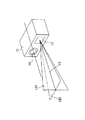
狭域用センサ(第2のセンサ手段)として採用されているレーザセンサ10は、周知のスポット光投射型あるいはスリット光投射型いずれであっても良いが、ここでは後者を採用したケースについて、図2を参照図に加えて述べる。
【0027】
レーザセンサ10のレーザ光照射部13は、レーザ発振器11及び12を備え、光検出部(受光部)14は受光素子14aと結像用の光学系14bを有している。レーザ発振器11及び12は、照射口付近に装備された円柱レンズを通してそれぞれスリット光LB1、LB2を出力する。
【0028】
また、レーザセンサ10は、レーザセンサ制御部20を介して画像処理装置2に接続されている。CCDカメラ30も、画像処理装置2に接続されている。このように、画像処理装置2は、レーザセンサ(本体部10と制御部20)とCCDカメラ30で共用される。
【0029】
回線24を介して画像処理装置2からレーザセンサの動作指令を受けると、レーザ駆動部21、22がレーザ発振器11、12を駆動し、レーザスリット光LB1、LB2を発生させる。
【0030】
対象物面上の反射点S1(スリット光LB1の任意の1本のビームL1の入射点)、S2(スリット光LB2の任意の1本のビームL2の入射点)で拡散反射されたレーザ光は、光学系14bにより反射点S1、S2の位置に応じて受光素子14a上に像を作る。該受光素子には、CCDなどが利用出来る。本例では、受光素子14aとして2次元CCDアレイが使用されている。
【0031】
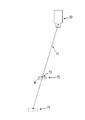
図3には、2つのレーザスリット光LB1、LB2が乗る平面、その交線LC、光照射部13、光検出部14等の位置関係が描かれている。レーザセンサ10に関するキャリブレーションは完了しており、その結果(キャリブレーションデータ)は画像処理装置2内のメモリに格納されている。レーザセンサ10のキャリブレーションデータには、2つのレーザスリット光LB1、LB2が乗る平面(2つ)がレーザセンサ10の本体に対してなす位置と姿勢(固定的な値)が含まれる。また、交線LCについても、それら平面のデータから随時計算し得る。
【0032】
従って、レーザセンサ10の本体(センサに固定された座標系の位置、姿勢)とロボットに設定された座標系(ロボット座標系;例えばロボット40のアーム先端に固定された座標系)との関係を求めておけば、レーザスリット光LB1、LB2が乗る平面及び交線LCのロボット座標系上での位置と方向が既知となる。周知のように、この関係は一般に4行×4列の同次変換行列で表わされ、レーザセンサのキャリブレーションで求められる。ここでは、このキャリブレーションも完了し、そのデータは画像処理装置2内のメモリに格納されている。
【0033】
以下、図4〜図6を参照図に加えて本実施形態におけるシステムの動作のプロセスを説明する。
通常、画像処理装置2はロボットコントローラ1からワーク検出指令が来るのを待っている(S1)。ワーク検出指令を受信したならば、ワーク検出のための処理シーケンスが進み、CCDカメラに撮影指令が出力され(S2)、ワークWの画像を含むワークパレット50全体の2次元画像が取得され、画像処理装置2内のフレームメモリに格納される(S3)。
【0034】
この画像の一例を示せば図5のようになっている。図5において、符号70は検出されたワークWの代表点(例えばワーク輪郭画像の重心)であり、この代表点70の2次元画像上の位置(u70、v70)が、画像処理装置2内で画像処理プロセッサを用いて求められる。更に、この2次元画像上の位置(u70、v70)に対応する視線32が、キャリブレーションで得たデータから計算される。
【0035】
ワークWを代表する点70はこの視線上にあるから、この視線の位置、姿勢(ワーク座標系上での方程式)が、この段階で判っている「ワークWの位置、姿勢(の情報)」となる。ここではこれをロボット座標系上のデータに変換したものを求める(S4)。なお、この変換には、ロボットコントローラ1のメモリに格納されている座標系設定データ(ロボット座標系とワーク座標系の関係を表わす4行×4列の同次変換行列)が利用される。
【0036】
ここで注意すべきことは、点70で代表されるワークWの位置には、不確定さが残っていることである。即ち、図6に示すように、透視変換の原理により、ワークW(代表点70)の3次元空間上での位置は視線32上に限定されるが、ワークWとカメラ30との間の距離が未知なので、視線32上での遠近は判らない。例えば、位置75と位置76の判別が出来ない。
【0037】
この視線32の情報(ロボット座標系上)は、「第1のセンサ手段と対象物を結ぶ直線」を表わす情報としてロボットコントローラ1に送られる(S5)。
【0038】
次に、ロボット40に搭載されたレーザセンサ10(第2のセンサ手段)を用いて対象物Wを認識(計測)するに適した位置、姿勢が計算される(S6)。この計算は、ロボットコントローラ1内で行なわれて良い。この計算において使われる条件の1つは、「視線32と交線LC(図3参照)を一致させる」という条件である。レーザセンサ10の遠近の条件については、予め適当な付加条件を課しておけば良い。
【0039】
付加条件は、例えばワーク座標系をパレット50上にXY平面が乗るように設定しておき、「ロボット40の位置のワーク座標系上でのZ座標値が一定値Z0 である」とすれば良い。ロボットコントローラ1は、これら条件の下で算出された位置、姿勢へロボット40を移動させる。なお、レーザセンサ10の交線LCの「向き」を指定する情報が必要になるが、これについても、上記ワーク座標系を使って、ロボット40の姿勢の1成分(ワーク座標系上)に条件を付けておけば良い(レーザセンサ10が下向きとなるようなロボット姿勢の指定)。
【0040】
この移動が完了した時点で、レーザセンサ10は、レーザスリット光LB1、LB2を、その交線LCが視線32に一致し、交線LCが点70で対象物70に遭遇するように照射し得る状態にある。
【0041】
移動が終るとロボットコントローラ1から画像処理装置2へ移動完了が伝えられる。すると、画像処理装置2はレーザセンサ10に撮影指令(動作指令)を出力する(S7)。すると、レーザセンサ10が動作し、レーザスリット光LB1、LB2が照射され、その交線LCは点70で対象物70に遭遇する(S8)。
【0042】
ここで、レーザセンサ10は3次元センサであるから、点70で代表される対象物の3次元位置が計測出来る。また、レーザスリット光LB1、LBに対応する反射像(受光素子14a上)から、対象物Wの姿勢なども検出出来る(S9)。
【0043】
従って、ワークWが他のワークの上に斜めに乗り上げているような場合や、ワークWの高さが一定でない場合であっても、それら(高さ、傾斜など)を検出することが出来る。そのため、その高さ、傾斜に合わせてロボット40による把持時の位置、姿勢を制御することが可能となる。
【0044】
なお、一旦、レーザセンサ10の交線LCで対象物Wを捉えた後であれば、ロボット40の位置あるいは姿勢を少量変えて点70以外に交線LCを入射させる条件で測定を行ない、より詳細な情報を得ることも容易である。
【0045】
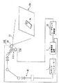
次に、図7は別の実施形態(変形実施形態)で使用可能な配置を示している。この変形実施形態は、パレット50の大きさ(広域センサの要カバー範囲)が余り大きくない場合に適している。
【0046】
図7に示した配置が上記実施形態(図1)と異なっているのは、レーザセンサの受光部に第1のセンサ手段の役割を兼備させることに対応して、CCDカメラ30がロボット40に、レーザセンサ110の受光部140として搭載されていることである。光照射部130は、レーザセンサ10の光照射部13と同様である。その他は、変形実施形態は図1に示した配置と共通した構成を有している。
【0047】
但し、レーザセンサ110のCCDカメラ30は、前述の実施形態と同様の撮影時に2次元画像を取得するために使用するモードと、レーザセンサ110のレーザスリット光の反射光検知のモードの切換使用が可能なように画像処理装置2あるいはロボットコントローラ1に格納されるシステム動作のためのソフトウェアが変更されている。また、CCDカメラ30と同様のキャリブレーションが受光部(結像レンズ付きであることに注意)14について完了し、キャリブレーションで得たデータが画像処理装置20のメモリに格納済みであるとする。
【0048】
本変形実施形態におけるシステムの動作のプロセスの概略は次のようになる。なお、前述の実施形態と重複する説明は極力避ける。
【0049】
画像処理装置2がロボットコントローラ1からワーク検出指令を受信したならば、レーザセンサ制御部20に通常撮影モードの動作指令が出力され、ワークWの画像を含むワークパレット50全体の2次元画像がCCDカメラ30によって取得され、画像処理装置2内のフレームメモリに格納される。
【0050】
この画像の例は図5に示した通りである。前述の実施形態と同様に、代表点70の2次元画像上の位置(u70、v70)から視線32が、キャリブレーションで得たデータを使って計算される。
【0051】
この視線32(即ち、レーザセンサ110の受光部140の受光軸)の情報(ロボット座標系上)は、「第1のセンサ手段と対象物を結ぶ直線」を表わす情報としてロボットコントローラ1に送られる。
【0052】
次に、ロボット40に搭載されたレーザセンサ110(第2のセンサ手段)を用いて対象物Wを認識(計測)するに適した位置、姿勢が計算される。この計算はは、ロボットコントローラ1内で行なわれて良い。この計算において使われる条件は、前述の実施形態と同様で良い。即ち、「視線32と交線LC(図3参照)を一致させる」という条件と、レーザセンサ110の遠近の条件を定める適当な付加条件である。
【0053】
この移動が完了するとロボットコントローラ1から画像処理装置2へ移動完了が伝えられ、画像処理装置2はレーザセンサ110にレーザスリット光撮影モードでの撮影指令を出力する。すると、レーザセンサ110が動作し、レーザスリット光LB1、LB2が照射され、その交線LCは点70で対象物70に遭遇する。レーザスリット光LB1、LB2の反射像は、CCDカメラ30の受光素子上に結像する。画像処理装置2は、レーザセンサ10の通常の機能を遂行するためのソフトウェア処理に従って検出結果を解析し、対象物Wの3次元的な位置、姿勢取得する。
【0054】
なお、上述した2つの実施形態では、第2のセンサ手段は3次元センサとしたが、用途によっては、2次元センサでも良い。その場合でも、例えば、第1のセンサで定めた「対象物と第1のセンサを結ぶ直線」に基づいて認識位置・姿勢(対象物の認識を行なうセンサの位置と姿勢)を定めることが出来る点に変わりはない。
【0055】
また、上述の各実施形態ではセンサの移動手段にロボットを使用したが、センサの位置、姿勢を制御出来るものであれば、他の移動手段(例えば姿勢制御可能なXYZテーブル)が使用されても良いことは明らかである。
【0056】
【発明の効果】
本願発明によれば、対象物の位置、高さ、姿勢などが不特定なケースであっても、第1のセンサ手段の取得する2次元画像を利用して定められる「対象物と第1のセンサを結ぶ直線」に基づいて、第2のセンサ手段による認識位置・姿勢を対象物の捉え損ねなしに適正に定められるので、各種の作業の自動化に資するところが大きい。
【図面の簡単な説明】
【図1】本願発明の1つの実施形態に係る3次元位置姿勢認識システムの全体配置の概要を説明する図である。
【図2】レーザセンサの構成と動作の概要を説明するための図である。
【図3】2つのレーザスリット光LB1、LB2が乗る平面、その交線LC、光照射部13、光検出部14等の位置関係を描いた図である。
【図4】実施形態における動作のプロセスを説明するフローチャートである。
【図5】第1のセンサ手段により取得される2次元画像のの一例を示した図である。
【図6】視線と対象物の関係について説明する図である。
【図7】図7は別の実施形態(変形実施形態)で使用可能な配置を示している。
【符号の説明】
1 ロボットコントローラ
2 画像処理装置
10、110 レーザセンサ(本体部)
11、12 レーザ発振器
13、130 レーザ光照射部
14、140 光検出部(受光部)
14a 受光素子(2次元CCDアレイ)
14b 結像用の光学系
20 レーザセンサ制御部
30 CCDカメラ
32 視線
40 ロボット
70 ワークの代表点
W ワーク
LB1、LB2 レーザスリット光
LC LB1、LB2の交線[0001]
TECHNICAL FIELD OF THE INVENTION
The present invention relates to a position and orientation recognition device applicable to various factory automations, and more specifically, a combined position and orientation measurement device that appropriately uses a sensor for acquiring two-dimensional information and a sensor for acquiring three-dimensional information as appropriate. About.
[0002]
[Prior art]
2. Description of the Related Art In an assembly operation, a processing operation, and the like in a production line, the position and shape of various objects are frequently detected using various sensors. Usually, a sensor capable of acquiring a two-dimensional image is effective for globally measuring the position of an object. For example, when using a CCD camera, it is easy to have a relatively wide field of view by appropriately selecting an optical system (lens). On the other hand, a laser sensor is effective for three-dimensionally measuring a local position or shape.
[0003]
The laser sensor is easy to mount on the robot hand.When the output of the laser sensor is incorporated into the robot controller, the laser beam is projected onto the object from a short distance to determine the position and shape of the details of the object. It has features such as accurate and real-time measurement. Therefore, laser sensors are frequently provided in robot systems and the like, and are widely used in fields such as arc welding, sealing, and measurement.
[0004]
Laser sensors include those that scan laser light with a spot light beam and those that project slit light. Regardless of which type of laser sensor is used, the spot light beam or slit light must be reliably projected onto the object surface. If the target object is positioned at a certain position with a certain degree of accuracy, a spot light beam or slit light is projected on the target object surface by previously teaching a position near the certain position as an approach position to the robot. It is easy to bring out a state quickly.
[0005]
However, depending on the application, there are many cases where the positioning of the object is unknown because it is not performed, or where the accuracy of the positioning is not reliable. In such a case, the target is searched using the spot light beam or slit light of the laser sensor as a probe while moving using a moving means such as a robot. Measurement (for example, shape measurement) cannot be started.
[0006]
Since a laser sensor is originally not suitable for measuring a wide range, it takes time to search for an object and then approach the object, and in some cases, it is difficult to search for the object reliably. It is possible.
[0007]
[Problems to be solved by the invention]
Therefore, an object of the present invention is to make it possible to use a sensor that can only sense a relatively small area, such as a laser sensor, even if the position and orientation of the object are unknown, It is an object of the present invention to provide a recognition device which can surely recognize two-dimensional information or three-dimensional information at an appropriate position and posture.
[0008]
[Means for Solving the Problems]
The recognition device according to the present invention first has, as prerequisites, first sensor means for acquiring two-dimensional information in a target area, and information in the target area in a relatively narrow area as compared with the target area. And second sensor means for acquiring Here, the information acquired by the second sensor means is two-dimensional information or three-dimensional information.
[0009]
The recognition apparatus of the present invention recognizes an object whose distance is unknown, and includes two-dimensional information including information on the object acquired by the first sensor means, and a position of the first sensor means. Means for obtaining a straight line in a three-dimensional space connecting the object and the first sensor means based on the position and the posture, and the second sensor enabling recognition of the object by the second sensor means Means for determining the position and orientation of the means from the straight line, and means for moving the second sensor means to the determined position and attitude.
[0010]
Then, the recognition device of the present invention, after moving the second sensor means to the position and orientation determined above by the moving means, uses the second sensor means to obtain two-dimensional information or three-dimensional information of the same object. By acquiring the position and orientation information, two-dimensional information or three-dimensional information of the same object is recognized.
[0011]
The second sensor unit acquires two-dimensional information, and the first sensor unit may also serve as the second sensor unit. Further, the second sensor means may include a light irradiating means and a light receiving means and have a function of performing three-dimensional position and orientation measurement.
[0012]
In this case, the light receiving means may be a two-dimensional sensor for acquiring two-dimensional information, and the second sensor means may also serve as the first sensor means.
[0013]
In the case where the second sensor means has a light irradiation means and a light receiving means and has a function of performing three-dimensional position and orientation measurement, the position and orientation at which the second sensor means recognizes an object are light and The direction of light irradiation of the irradiating means may be determined so as to coincide with the above-mentioned straight line (the straight line connecting the object and the first sensor means), and the optical axis direction of the light receiving means coincides with the same straight line. May be determined.
[0014]
In any of the above cases, the means for finding the straight line in the three-dimensional space or the means for finding the position and orientation of the second sensor means may be provided in the robot controller of the industrial robot. . Further, an industrial robot can be used as a means for moving the second sensor means to a position and a posture determined as a proper place for performing recognition.
[0015]
An important point of the present invention is that the first sensor means capable of acquiring two-dimensional information within a relatively wide area first finds an object, and at that time, a space (real 3) connecting the first sensor means and the object. A “straight line” on the (dimensional space) is obtained, and the “straight line obtained” is referred to as “the target object” of the second sensor means suitable for acquiring two-dimensional information or three-dimensional information in a relatively small area. It is used to determine “position and posture suitable for recognition (observation)”.
[0016]
According to a specific procedure, first, a first sensor acquires a two-dimensional image of a target area, processes the same two-dimensional image to find an object on the two-dimensional image, To detect the position of the object at. Here, the “target region” is a region that can cover a range in which there is a possibility that the target exists.
[0017]
What is known at this stage is that the position of the object in (real 3D) space is on the “line of sight” of the camera of the first sensor capturing the object. That is, the distance of the object is unknown. As is well known, this “line of sight” is determined from data obtained by camera calibration of the first sensor as a straight line connecting the lens center of the camera lens and the imaging position of the same object on the imaging plane. I can do it.
[0018]
In other words, from the data obtained by the calibration, it is possible to know the relationship between “the imaging position of the same object on the imaging surface” to “the position of the object on the image” and “the position and direction of the line of sight”. I can do it.
[0019]
Generally speaking, if the position (u, v) in the image space (two-dimensional) is known, the line of sight (straight line) passing through the position is known. The equation represented by this line of sight (straight line) is also called a “line of sight equation”.
[0020]
Therefore, this line of sight can be used as a “straight line connecting the first sensor and the object”. Strictly speaking, “the position of the object” means “the position of a certain point (referred to as a representative point) on the object”, and “the straight line connecting the first sensor and the object” means , "A straight line connecting the first sensor and a representative point on the object".
[0021]
By the way, the “straight line connecting the first sensor and the object” obtained in this manner is used for more detailed recognition (for example, more accurate position, posture, shape, and size of the object) performed using the second sensor. Etc.) are effectively used to determine the appropriate position and orientation. Because the object is definitely on the “straight line in the space” obtained, the second sensor is moved on or near the straight line, and the second sensor is moved to the direction matching the straight line. If an attitude is taken such that the field of view of the sensor is turned, the target object can be reliably captured.
[0022]
For example, if the second sensor includes a light irradiation unit and a light receiving unit and has a function of performing three-dimensional position and orientation measurement, the second sensor is based on the direction of light irradiation or the direction of the optical axis of the light receiving unit. The attitude of the second sensor may be determined.
[0023]
BEST MODE FOR CARRYING OUT THE INVENTION
FIG. 1 is a diagram illustrating an outline of an overall arrangement of a three-dimensional position and orientation recognition system according to one embodiment of the present invention. As an example, the system is applied to handling (pickup and transport) of a workpiece by a robot (industrial robot; the same applies hereinafter). Here, a plurality of workpieces are in different positions and postures. When the handling operation is started from such a state, the present system exhibits its features.
[0024]
As shown in FIG. 1, the entire system includes a
[0025]
It is assumed that the above-described calibration for previously knowing the relationship between the position (u, v) in the image space (two-dimensional) and the line of sight (straight line) for the
[0026]
The
[0027]
The laser
[0028]
The
[0029]
When an operation command of the laser sensor is received from the image processing apparatus 2 via the
[0030]
The laser light diffusely reflected at the reflection point S1 (the point of incidence of any one beam L1 of the slit light LB1) and S2 (the point of incidence of any one beam L2 of the slit light LB2) on the object surface is The
[0031]
FIG. 3 illustrates a plane on which the two laser slit lights LB1 and LB2 ride, a crossing line LC thereof, and a positional relationship between the
[0032]
Therefore, the relationship between the main body of the laser sensor 10 (the position and orientation of the coordinate system fixed to the sensor) and the coordinate system set for the robot (robot coordinate system; for example, a coordinate system fixed to the end of the arm of the robot 40) is defined. If obtained, the position and direction of the plane on which the laser slit beams LB1 and LB2 ride and the intersection line LC on the robot coordinate system are known. As is well known, this relationship is generally represented by a homogenous transformation matrix of 4 rows × 4 columns, and is obtained by calibration of the laser sensor. Here, this calibration is also completed, and the data is stored in the memory in the image processing apparatus 2.
[0033]
Hereinafter, a process of an operation of the system according to the present embodiment will be described in addition to FIGS. 4 to 6.
Normally, the image processing apparatus 2 waits for a work detection command from the robot controller 1 (S1). When the work detection command is received, the processing sequence for work detection proceeds, a shooting command is output to the CCD camera (S2), and a two-dimensional image of the
[0034]
An example of this image is as shown in FIG. In FIG. 5,
[0035]
Since the
[0036]
What should be noted here is that uncertainty remains at the position of the work W represented by the
[0037]
The information of the line of sight 32 (on the robot coordinate system) is sent to the
[0038]
Next, a position and a posture suitable for recognizing (measuring) the object W are calculated using the laser sensor 10 (second sensor means) mounted on the robot 40 (S6). This calculation may be performed in the
[0039]
The additional condition may be set, for example, such that the work coordinate system is set on the
[0040]
When this movement is completed, the
[0041]
When the movement is completed, the
[0042]
Here, since the
[0043]
Therefore, even when the work W is running obliquely on another work or when the height of the work W is not constant, it is possible to detect them (height, inclination, etc.). Therefore, it is possible to control the position and posture at the time of gripping by the
[0044]
Note that once the target W is captured by the intersection line LC of the
[0045]
Next, FIG. 7 shows an arrangement that can be used in another embodiment (modified embodiment). This modified embodiment is suitable when the size of the pallet 50 (the required range of the wide area sensor) is not too large.
[0046]
The arrangement shown in FIG. 7 differs from that of the above-described embodiment (FIG. 1) in that the
[0047]
However, the
[0048]
The outline of the process of the operation of the system in the present modified embodiment is as follows. In addition, the description which overlaps with the above-mentioned embodiment is avoided as much as possible.
[0049]
When the image processing device 2 receives a work detection command from the
[0050]
An example of this image is as shown in FIG. As in the above-described embodiment, the line of
[0051]
The information of the line of sight 32 (that is, the light receiving axis of the
[0052]
Next, a position and a posture suitable for recognizing (measuring) the object W are calculated using the laser sensor 110 (second sensor means) mounted on the
[0053]
When this movement is completed, the completion of the movement is transmitted from the
[0054]
In the two embodiments described above, the second sensor means is a three-dimensional sensor, but may be a two-dimensional sensor depending on the application. Even in such a case, for example, the recognition position / posture (the position and the posture of the sensor for recognizing the object) can be determined based on the “straight line connecting the object and the first sensor” determined by the first sensor. The point remains the same.
[0055]
In each of the embodiments described above, the robot is used as the sensor moving means. However, other moving means (for example, an XYZ table capable of controlling the posture) may be used as long as the position and the posture of the sensor can be controlled. The good is clear.
[0056]
【The invention's effect】
According to the present invention, even when the position, height, posture, and the like of the object are unspecified, the “object and first object” determined using the two-dimensional image acquired by the first sensor unit are used. Based on the "straight line connecting the sensors", the position and orientation recognized by the second sensor means can be properly determined without failing to catch the target object, which greatly contributes to automation of various operations.
[Brief description of the drawings]
FIG. 1 is a diagram illustrating an outline of an overall arrangement of a three-dimensional position and orientation recognition system according to an embodiment of the present invention.
FIG. 2 is a diagram for explaining an outline of a configuration and an operation of a laser sensor.
FIG. 3 is a diagram illustrating a plane on which two laser slit lights LB1 and LB2 ride, a line of intersection LC, a
FIG. 4 is a flowchart illustrating an operation process according to the embodiment.
FIG. 5 is a diagram showing an example of a two-dimensional image obtained by a first sensor unit.
FIG. 6 is a diagram illustrating a relationship between a line of sight and an object.
FIG. 7 shows an arrangement that can be used in another embodiment (modified embodiment).
[Explanation of symbols]
11, 12
14a Light receiving element (two-dimensional CCD array)
Claims (9)
前記第1のセンサ手段により取得された対象物の情報を含む2次元情報と、前記第1のセンサ手段の位置及び姿勢とに基づいて、前記対象物と前記第1のセンサ手段とを結ぶ3次元空間上の直線を求める手段と;
前記第2のセンサ手段による前記対象物の認識が可能になる該第2のセンサ手段の位置及び姿勢を前記3次元空間上の直線から求める手段と;前記第2のセンサ手段を前記求めた位置及び姿勢に移動させる手段とを備え、
前記移動手段により前記第2のセンサ手段を前記求めた位置及び姿勢に移動させた後に、前記第2のセンサ手段により前記対象物の2次元情報または3次元的な位置姿勢情報を取得することにより、前記対象物の2次元情報または3次元情報を認識することを特徴とする、認識装置。First sensor means for acquiring two-dimensional information in a target area, and second sensor means for acquiring two-dimensional information or three-dimensional information in a target area in a relatively narrow area compared to the target area In a position and orientation recognition apparatus for recognizing an object whose distance is unknown , including:
3 connecting the object and the first sensor means based on the two-dimensional information including the information of the object acquired by the first sensor means and the position and orientation of the first sensor means. Means for finding a straight line in a dimensional space;
Means for obtaining, from the straight line in the three-dimensional space, the position and orientation of the second sensor means by which the object can be recognized by the second sensor means; and the obtained position of the second sensor means And means for moving to a posture,
After moving the second sensor means to the obtained position and posture by the moving means, by acquiring two-dimensional information or three-dimensional position and posture information of the object by the second sensor means A recognition device for recognizing two-dimensional information or three-dimensional information of the object.
前記第2のセンサ手段が、前記第1のセンサ手段を兼ねていることを特徴とする、請求項1に記載された認識装置。The second sensor is for acquiring two-dimensional information,
The recognition device according to claim 1, wherein the second sensor means also serves as the first sensor means.
Priority Applications (4)
| Application Number | Priority Date | Filing Date | Title |
|---|---|---|---|
| JP2000285526A JP3556589B2 (en) | 2000-09-20 | 2000-09-20 | Position and orientation recognition device |
| US09/950,794 US7171041B2 (en) | 2000-09-20 | 2001-09-13 | Position-orientation recognition device |
| DE60121105T DE60121105T2 (en) | 2000-09-20 | 2001-09-19 | Device for position orientation recognition |
| EP01307958A EP1190818B1 (en) | 2000-09-20 | 2001-09-19 | Position-orientation recognition device |
Applications Claiming Priority (1)
| Application Number | Priority Date | Filing Date | Title |
|---|---|---|---|
| JP2000285526A JP3556589B2 (en) | 2000-09-20 | 2000-09-20 | Position and orientation recognition device |
Publications (2)
| Publication Number | Publication Date |
|---|---|
| JP2002090113A JP2002090113A (en) | 2002-03-27 |
| JP3556589B2 true JP3556589B2 (en) | 2004-08-18 |
Family
ID=18769581
Family Applications (1)
| Application Number | Title | Priority Date | Filing Date |
|---|---|---|---|
| JP2000285526A Expired - Fee Related JP3556589B2 (en) | 2000-09-20 | 2000-09-20 | Position and orientation recognition device |
Country Status (4)
| Country | Link |
|---|---|
| US (1) | US7171041B2 (en) |
| EP (1) | EP1190818B1 (en) |
| JP (1) | JP3556589B2 (en) |
| DE (1) | DE60121105T2 (en) |
Cited By (1)
| Publication number | Priority date | Publication date | Assignee | Title |
|---|---|---|---|---|
| US9746855B2 (en) | 2012-09-03 | 2017-08-29 | Canon Kabushiki Kaisha | Information processing system, method, and program |
Families Citing this family (39)
| Publication number | Priority date | Publication date | Assignee | Title |
|---|---|---|---|---|
| JP3859571B2 (en) * | 2002-10-17 | 2006-12-20 | ファナック株式会社 | 3D visual sensor |
| JP3859574B2 (en) | 2002-10-23 | 2006-12-20 | ファナック株式会社 | 3D visual sensor |
| DE102004005574B3 (en) * | 2004-02-05 | 2005-07-14 | Daimlerchrysler Ag | Robot system with tool, camera and light source for manipulating tool for processing workpiece has light source and camera independently movable in order to illuminate field of view from different directions |
| JP4508820B2 (en) * | 2004-10-19 | 2010-07-21 | 株式会社ワコム | 3D information detection system and 3D information input device |
| US20070277919A1 (en) | 2006-05-16 | 2007-12-06 | The Boeing Company | Systems and methods for monitoring automated composite manufacturing processes |
| EP2036660A1 (en) * | 2007-09-12 | 2009-03-18 | Hans Oxenfarth | Method and device for position and angle compensated part mounting |
| KR101461185B1 (en) | 2007-11-09 | 2014-11-14 | 삼성전자 주식회사 | Apparatus and method for building 3D map using structured light |
| JP5198078B2 (en) * | 2008-01-24 | 2013-05-15 | 株式会社日立製作所 | Measuring device and measuring method |
| ITTO20080450A1 (en) * | 2008-06-11 | 2009-12-12 | Opm S P A | METHOD AND GROUP OF DETECTION AND COMMAND FOR TAKING PRODUCTS |
| JP2010112975A (en) * | 2008-11-04 | 2010-05-20 | Nidec Sankyo Corp | Drive unit for movable plate |
| JP5282717B2 (en) * | 2009-10-19 | 2013-09-04 | 株式会社安川電機 | Robot system |
| TWI404609B (en) * | 2010-10-21 | 2013-08-11 | Ind Tech Res Inst | Parameters adjustment method of robotic arm system and adjustment apparatus |
| CN102859319A (en) * | 2011-04-19 | 2013-01-02 | 三洋电机株式会社 | Information acquisition device and object detection device |
| CN103959763B (en) * | 2011-12-09 | 2017-06-09 | 惠普发展公司,有限责任合伙企业 | Apparatus and method for generating image based on orientation |
| JP5854815B2 (en) * | 2011-12-20 | 2016-02-09 | キヤノン株式会社 | Information processing apparatus, information processing apparatus control method, and program |
| JP6000579B2 (en) * | 2012-03-09 | 2016-09-28 | キヤノン株式会社 | Information processing apparatus and information processing method |
| JP5975685B2 (en) | 2012-03-09 | 2016-08-23 | キヤノン株式会社 | Information processing apparatus and information processing method |
| JP5977544B2 (en) | 2012-03-09 | 2016-08-24 | キヤノン株式会社 | Information processing apparatus and information processing method |
| CN102645219B (en) * | 2012-05-16 | 2014-12-03 | 航天科工哈尔滨风华有限公司 | Welding and locating method of welding seam and method of obtaining welding seam offset for visual navigation system of wall climbing robot for weld inspection |
| DE102014100538B4 (en) * | 2014-01-17 | 2022-09-08 | Pi4_Robotics Gmbh | Method for calibrating a robot and a camera and system for performing the method |
| CN103776378A (en) * | 2014-02-27 | 2014-05-07 | 上海思琢自动化科技有限公司 | Non-contact type flexible on-line dimension measurement system |
| CN105091678B (en) * | 2014-05-20 | 2017-03-29 | 中国能源建设集团有限公司工程研究院 | A kind of comprehensive powder charge automatic seeking hole method of underground explosion, apparatus and system |
| JP2016070762A (en) * | 2014-09-29 | 2016-05-09 | ファナック株式会社 | Detection method and detector for detecting three-dimensional position of object |
| CN104280740A (en) * | 2014-10-11 | 2015-01-14 | 三峡大学 | Device for jointly positioning blast hole based on camera and laser distance measuring sensor and positioning method |
| CN104359423B (en) * | 2014-11-18 | 2017-02-22 | 刘杰波 | Surface profile measuring device |
| DE102015100983A1 (en) * | 2015-01-23 | 2016-07-28 | Sick Ag | Method for locating gripping points of objects |
| CN104858870A (en) * | 2015-05-15 | 2015-08-26 | 江南大学 | Industrial robot measurement method based on tail end numbered tool |
| CN105139005A (en) * | 2015-09-23 | 2015-12-09 | 无锡市中捷减震器有限公司 | Detection device with workpiece identification and marking functions |
| JP2018051728A (en) * | 2016-09-30 | 2018-04-05 | ファナック株式会社 | Detection method and detection apparatus for detecting three-dimensional position of object |
| JP2018176334A (en) | 2017-04-10 | 2018-11-15 | キヤノン株式会社 | Information processing device, measurement device, system, interference determination method and article manufacturing method |
| US10894676B2 (en) | 2017-07-17 | 2021-01-19 | Symbolic Llc | Apparatus and method for building a pallet load |
| JP7062911B2 (en) | 2017-10-11 | 2022-05-09 | セイコーエプソン株式会社 | Robot system |
| CN109978925B (en) * | 2017-12-27 | 2021-04-20 | 深圳市优必选科技有限公司 | Robot pose recognition method and robot thereof |
| CN110842908A (en) * | 2018-08-21 | 2020-02-28 | 广州弘度信息科技有限公司 | Robot and auxiliary positioning method thereof |
| CN110231036B (en) * | 2019-07-19 | 2020-11-24 | 广东博智林机器人有限公司 | Robot positioning device and method based on cross laser and machine vision |
| CN114643599B (en) * | 2020-12-18 | 2023-07-21 | 沈阳新松机器人自动化股份有限公司 | Three-dimensional machine vision system and method based on point laser and area array camera |
| WO2023276238A1 (en) * | 2021-07-02 | 2023-01-05 | ソニーグループ株式会社 | Robot control device and robot control method |
| WO2023053395A1 (en) * | 2021-09-30 | 2023-04-06 | ファナック株式会社 | Position and posture measurement system |
| WO2023171687A1 (en) * | 2022-03-08 | 2023-09-14 | 京セラ株式会社 | Robot control device and robot control method |
Family Cites Families (5)
| Publication number | Priority date | Publication date | Assignee | Title |
|---|---|---|---|---|
| US4985846A (en) * | 1989-05-11 | 1991-01-15 | Fallon Patrick J | Acoustical/optical bin picking system |
| CA2089017C (en) * | 1992-02-13 | 1999-01-19 | Yasurou Yamanaka | Method of mounting wheel to vehicle |
| JPH0970780A (en) * | 1995-09-06 | 1997-03-18 | Fanuc Ltd | Tool shape correcting method of robot |
| EP0812662B1 (en) | 1995-12-27 | 2008-01-23 | Fanuc Ltd | Composite sensor robot system |
| US6415051B1 (en) * | 1999-06-24 | 2002-07-02 | Geometrix, Inc. | Generating 3-D models using a manually operated structured light source |
-
2000
- 2000-09-20 JP JP2000285526A patent/JP3556589B2/en not_active Expired - Fee Related
-
2001
- 2001-09-13 US US09/950,794 patent/US7171041B2/en not_active Expired - Lifetime
- 2001-09-19 DE DE60121105T patent/DE60121105T2/en not_active Expired - Lifetime
- 2001-09-19 EP EP01307958A patent/EP1190818B1/en not_active Expired - Lifetime
Cited By (1)
| Publication number | Priority date | Publication date | Assignee | Title |
|---|---|---|---|---|
| US9746855B2 (en) | 2012-09-03 | 2017-08-29 | Canon Kabushiki Kaisha | Information processing system, method, and program |
Also Published As
| Publication number | Publication date |
|---|---|
| EP1190818A2 (en) | 2002-03-27 |
| DE60121105T2 (en) | 2006-11-16 |
| DE60121105D1 (en) | 2006-08-10 |
| EP1190818B1 (en) | 2006-06-28 |
| EP1190818A3 (en) | 2004-01-21 |
| US20020034327A1 (en) | 2002-03-21 |
| JP2002090113A (en) | 2002-03-27 |
| US7171041B2 (en) | 2007-01-30 |
Similar Documents
| Publication | Publication Date | Title |
|---|---|---|
| JP3556589B2 (en) | Position and orientation recognition device | |
| JP5290324B2 (en) | Method and system for accurately positioning at least one object in a final pose in space | |
| US5461478A (en) | Method and apparatus for measuring three-dimensional position and orientation of an object using light projection | |
| US4611292A (en) | Robot vision system | |
| EP0812662B1 (en) | Composite sensor robot system | |
| US6763284B2 (en) | Robot teaching apparatus | |
| JP3377465B2 (en) | Image processing device | |
| JP4015161B2 (en) | Industrial robot controller | |
| US20080252248A1 (en) | Device and Method for Calibrating the Center Point of a Tool Mounted on a Robot by Means of a Camera | |
| JP2017019072A (en) | Position measurement system | |
| CN105190235A (en) | Compensation of a structured light scanner that is tracked in six degrees-of-freedom | |
| JP2000288968A (en) | Teaching model producing device | |
| JP2000288974A (en) | Robot device having image processing function | |
| JP2004508954A (en) | Positioning device and system | |
| US7502504B2 (en) | Three-dimensional visual sensor | |
| JP2007101197A (en) | Object search system, robot system equipped with object searchsystem and object search method | |
| US5363185A (en) | Method and apparatus for identifying three-dimensional coordinates and orientation to a robot | |
| JP2000009422A (en) | Distance measuring apparatus for traveling vehicle | |
| JP6869159B2 (en) | Robot system | |
| US20220048199A1 (en) | Referencing pose manipulation system for marker based tracking of position measurement system | |
| JP2004050356A (en) | Position and attitude sensor of movable structure | |
| JPS6332306A (en) | Non-contact three-dimensional automatic dimension measuring method | |
| JP6031368B2 (en) | Correlation positioning method with workpiece | |
| JPH0545117A (en) | Optical method for measuring three-dimensional position | |
| US20210270600A1 (en) | System and method |
Legal Events
| Date | Code | Title | Description |
|---|---|---|---|
| A02 | Decision of refusal |
Free format text: JAPANESE INTERMEDIATE CODE: A02 Effective date: 20031202 |
|
| A521 | Written amendment |
Free format text: JAPANESE INTERMEDIATE CODE: A523 Effective date: 20040203 |
|
| A911 | Transfer of reconsideration by examiner before appeal (zenchi) |
Free format text: JAPANESE INTERMEDIATE CODE: A911 Effective date: 20040218 |
|
| TRDD | Decision of grant or rejection written | ||
| A01 | Written decision to grant a patent or to grant a registration (utility model) |
Free format text: JAPANESE INTERMEDIATE CODE: A01 Effective date: 20040420 |
|
| A61 | First payment of annual fees (during grant procedure) |
Free format text: JAPANESE INTERMEDIATE CODE: A61 Effective date: 20040512 |
|
| R150 | Certificate of patent or registration of utility model |
Ref document number: 3556589 Country of ref document: JP Free format text: JAPANESE INTERMEDIATE CODE: R150 Free format text: JAPANESE INTERMEDIATE CODE: R150 |
|
| FPAY | Renewal fee payment (event date is renewal date of database) |
Free format text: PAYMENT UNTIL: 20080521 Year of fee payment: 4 |
|
| FPAY | Renewal fee payment (event date is renewal date of database) |
Free format text: PAYMENT UNTIL: 20090521 Year of fee payment: 5 |
|
| FPAY | Renewal fee payment (event date is renewal date of database) |
Free format text: PAYMENT UNTIL: 20100521 Year of fee payment: 6 |
|
| FPAY | Renewal fee payment (event date is renewal date of database) |
Free format text: PAYMENT UNTIL: 20110521 Year of fee payment: 7 |
|
| FPAY | Renewal fee payment (event date is renewal date of database) |
Free format text: PAYMENT UNTIL: 20110521 Year of fee payment: 7 |
|
| FPAY | Renewal fee payment (event date is renewal date of database) |
Free format text: PAYMENT UNTIL: 20120521 Year of fee payment: 8 |
|
| FPAY | Renewal fee payment (event date is renewal date of database) |
Free format text: PAYMENT UNTIL: 20120521 Year of fee payment: 8 |
|
| FPAY | Renewal fee payment (event date is renewal date of database) |
Free format text: PAYMENT UNTIL: 20130521 Year of fee payment: 9 |
|
| FPAY | Renewal fee payment (event date is renewal date of database) |
Free format text: PAYMENT UNTIL: 20130521 Year of fee payment: 9 |
|
| FPAY | Renewal fee payment (event date is renewal date of database) |
Free format text: PAYMENT UNTIL: 20140521 Year of fee payment: 10 |
|
| LAPS | Cancellation because of no payment of annual fees |