JP3552603B2 - Exhaust gas purification device for internal combustion engine - Google Patents
Exhaust gas purification device for internal combustion engine Download PDFInfo
- Publication number
- JP3552603B2 JP3552603B2 JP23405699A JP23405699A JP3552603B2 JP 3552603 B2 JP3552603 B2 JP 3552603B2 JP 23405699 A JP23405699 A JP 23405699A JP 23405699 A JP23405699 A JP 23405699A JP 3552603 B2 JP3552603 B2 JP 3552603B2
- Authority
- JP
- Japan
- Prior art keywords
- temperature
- nox catalyst
- reducing agent
- catalyst
- nox
- Prior art date
- Legal status (The legal status is an assumption and is not a legal conclusion. Google has not performed a legal analysis and makes no representation as to the accuracy of the status listed.)
- Expired - Lifetime
Links
Images


Description
【0001】
【発明の属する技術分野】
本発明は、希薄燃焼運転可能な内燃機関から排出される排気ガスを浄化する排気浄化装置に関し、特に、触媒により排気ガス中のNOxを浄化することができる排気浄化装置に係るものである。
【0002】
【従来の技術】
内燃機関から排出される排気ガス中の有害成分の大気への排出量を低減するための一手段として、触媒の酸化作用あるいは還元作用を利用して有害成分を浄化するシステムがある。
【0003】
近年の触媒に関する研究開発により触媒の性能向上は目覚ましいものがあり、小型でも浄化性能が高い触媒装置の実現が可能になった。その結果、近年、車両用内燃機関の排気ガスを浄化する排気浄化システムとして、触媒を組み込んだ排気浄化装置が多用されるに至っている。
【0004】
現在、実用に供されている排気ガス浄化用の触媒には、酸化触媒、三元触媒、NOx触媒などがあり、これら触媒を、内燃機関の燃焼形態や空燃比、あるいは浄化すべき有害物質の種類などに応じて使い分けている。
【0005】
これら触媒のうちNOx触媒は、希薄燃焼運転可能な内燃機関から排出される排気ガスを浄化することができる触媒として多用されており、NOx触媒には、選択還元型NOx触媒と吸蔵還元型NOx触媒がある。選択還元型NOx触媒とは、酸素過剰の雰囲気で炭化水素(HC)の存在下でNOxを還元または分解する触媒をいい、一方、吸蔵還元型NOx触媒とは、流入排気ガスの空燃比がリーンのときはNOxを吸収し、流入排気ガス中の酸素濃度が低下すると吸収したNOxを放出しN2に還元する触媒をいう。これらNOx触媒は、排気ガス中のHCを酸化して浄化する酸化作用と、排気ガス中のNOxを還元して浄化する還元作用を備えている。
【0006】
一般に、触媒を長期に亘って使用していると、その触媒が有する酸化作用や還元作用が衰えていく、いわゆる劣化が生じる。上記NOx触媒も例に漏れず、長期に亘って使用していると、酸化作用の衰えによりHC浄化能力が低下したり(これをHC劣化と区別する場合もある)、還元作用の衰えによりNOx浄化能力が低下したり(これをNOx劣化と区別する場合もある)する。劣化したNOx触媒を使用し続けると、排気ガス中の有害物質を浄化しきれなくなり、有害物質を含む排気ガスを大気中に排出する虞れがある。したがって、このような浄化能力の低下したNOx触媒に対しては交換等の措置が必要であり、そのためには触媒の浄化能力の管理(換言すれば、触媒の劣化判定)が極めて重要である。
【0007】
触媒の劣化判定技術に関しては、例えば特開平5−312024号公報に開示されているものがある。この公報に記載された技術では、触媒がその機能を発揮しているときには発熱を伴うことに着目し、その温度変化に基づいて触媒の劣化を判定する。
【0008】
詳述すると、内燃機関の排気通路に設けられたNOx触媒の上流と下流に排気ガス温度を検出する温度センサを設け、内燃機関の通常の運転状態における上流側の排気ガス温度と下流側の排気ガス温度の温度差を演算する。NOx触媒が正常に機能してHC,CO,NOxを浄化しているとき、NOx触媒は発熱するので、下流側の排気ガス温度が上流側の排気ガス温度よりも上昇する。ところが、NOx触媒の劣化が進行するにしたがってNOx触媒における発熱量が低下するため、下流側の排気ガス温度は上流側の排気ガス温度に近付いてくる。つまり、NOx触媒の劣化が進行するにしたがって、下流側の排気ガス温度と上流側の排ガス温度の差は小さくなる。そこで、下流側の排気ガス温度と上流側の排気ガス温度の温度差が予め設定した閾値以下になったときに、該NOx触媒が劣化したと判定する。
【0009】
【発明が解決しようとする課題】
前述した従来の触媒の劣化判定技術では、内燃機関の通常の運転状態におけるNOx触媒の上下流の排気ガス温度の差から劣化判定を実行するが、元々、内燃機関の通常の運転状態では、NOx触媒が劣化していないときでもNOx触媒における発熱量が小さいため、上下流の排気ガス温度差も小さい。このように正常時においても小さい値である温度差に基づいて劣化判定を行っているので、判定精度が低いという問題があった。
【0010】
本発明はこのような従来の技術の問題点に鑑みてなされたものであり、本発明が解決しようとする課題は、簡単な構造ながら、触媒の劣化を高精度で判定することができる内燃機関の排気浄化装置を提供することにある。
また、本発明の別の課題は、簡単な構造ながら、触媒の劣化程度に応じてNOx触媒への還元剤の供給量を最適に制御することができる内燃機関の排気浄化装置を提供することにある。
【0011】
【課題を解決するための手段】
本出願に係る発明は前記課題を解決するために、以下の手段を採用した。
(1)本出願に係る第1の発明の内燃機関の排気浄化装置は、希薄燃焼運転可能な内燃機関の排気通路に設けられたNOx触媒と、前記NOx触媒に還元剤を供給する還元剤供給手段と、前記NOx触媒の触媒温度あるいは前記NOx触媒の出口の排気ガス温度を検出する温度検出手段と、前記還元剤供給手段によって通常時の供給量よりも大量の還元剤を前記NOx触媒に供給したときに前記温度検出手段により検出した温度と第1の基準温度とを比較する温度比較手段と、前記温度比較手段の比較結果に基づいて前記NOx触媒が劣化しているか否かを判定する劣化判定手段と、を備えることを特徴とする。
【0012】
還元剤供給手段によって通常時の供給量よりも大量の還元剤を前記NOx触媒に供給したときには、NOx触媒が完全に劣化して触媒機能を失わない限り、NOx触媒における発熱量は通常時の還元剤供給量のときよりも大きくなる。したがって、このときに温度検出手段によって検出した温度(触媒温度あるいは触媒出口の排気ガス温度)と第1の基準温度とを比較した比較結果(比較値)は、通常時の還元剤供給量のときの比較結果(比較値)よりも明白になる。温度比較手段で得たこの明白な比較結果に基づいて、劣化判定手段がNOx触媒が劣化したか否かを判定するので、劣化判定の精度が高い。
【0013】
(2)本出願に係る第2の発明の内燃機関の排気浄化装置は、希薄燃焼運転可能な内燃機関の排気通路に設けられたNOx触媒と、前記NOx触媒に還元剤を供給する還元剤供給手段と、前記NOx触媒の触媒温度あるいは前記NOx触媒の出口の排気ガス温度を検出する温度検出手段と、前記還元剤供給手段によって通常時の供給量よりも大量の還元剤を前記NOx触媒に供給したときに前記温度検出手段により検出した温度と第1の基準温度とを比較する温度比較手段と、前記温度比較手段の比較結果に基づいて前記NOx触媒への通常時の還元剤供給量を補正する供給量補正手段と、を備えることを特徴とする。
【0014】
還元剤供給手段によって通常時の供給量よりも大量の還元剤を前記NOx触媒に供給したときには、NOx触媒が完全に劣化して触媒機能を失わない限り、NOx触媒における発熱量は通常時の還元剤供給量のときよりも大きくなる。したがって、このときに温度検出手段によって検出した温度(触媒温度あるいは触媒出口の排気ガス温度)と第1の基準温度とを比較した比較結果(比較値)は、通常時の還元剤供給量のときの比較結果(比較値)よりも明白になる。
【0015】
NOx触媒の劣化が進行するにしたがって浄化能力が低下するので、劣化前の通常時の還元剤供給量を劣化進行後において供給すると、還元剤が過量となってNOx触媒を通過しエミッションが悪化してしまう。そこで、この第2の発明の排気浄化装置では、温度比較手段で得た明白な比較結果に基づいて、供給量補正手段がNOx触媒への通常時の還元剤供給量を補正する。これによりNOx触媒の劣化進行に伴うエミッションの悪化を防止することができる。同時に還元剤の浪費を防止することができる。
【0016】
前述した第1の発明及び第2の発明において、内燃機関としては、ディーゼルエンジンあるいは希薄燃焼可能なガソリンエンジンを例示することができる。
前述した第1の発明及び第2の発明において、NOx触媒としては、選択還元型NOx触媒や吸蔵還元型NOx触媒を例示することができる。
【0017】
選択還元型NOx触媒は、酸素過剰の雰囲気で炭化水素の存在下でNOxを還元または分解する触媒をいい、例えば、ゼオライトにCu等の遷移金属をイオン交換して担持した触媒、ゼオライトまたはアルミナに貴金属を担持した触媒、等が含まれる。
【0018】
吸蔵還元型NOx触媒は、該触媒に流入する排気ガスの空燃比がリーンのときはNOxを吸収し、流入する排気ガス中の酸素濃度が低下すると吸収したNOxを放出しN2に還元する触媒をいう。吸蔵還元型NOx触媒は、例えばアルミナを担体とし、この担体上に例えばカリウムK、ナトリウムNa、リチウムLi、セシウムCsのようなアルカリ金属、バリウムBa、カルシウムCaのようなアルカリ土類、ランタンLa、イットリウムYのような希土類から選ばれた少なくとも一つと、白金Ptのような貴金属とが担持されてなる。
【0019】
前述した第1の発明及び第2の発明において、還元剤としては炭化水素(HC)が好適である。
前述した第1の発明及び第2の発明において、還元剤供給手段は、膨張行程あるいは排気行程において気筒内に燃料を副噴射する副噴射手段により構成することもできるし、内燃機関の気筒とNOx触媒の間の排気通路に還元剤を供給する還元剤供給装置で構成することもできる。さらに、理論空燃比あるいはリッチ空燃比で運転可能なガソリンエンジンの場合であれば、燃焼室に供給される混合気の空燃比を理論空燃比あるいはリッチ空燃比にして排気ガスの空燃比を理論空燃比あるいはリッチ空燃比にすることによりNOx触媒に還元剤を供給することができるので、その場合には、空燃比制御手段で還元剤供給手段を構成することができる。
【0020】
また、還元剤供給手段による還元剤の供給は、連続供給であってもよいし間欠供給であってもよく、どちらの供給方法を採用するかは、使用するNOx触媒の種類や、排気浄化装置の全体システムによって決定される。
前述した第1の発明及び第2の発明において、温度検出手段は、温度センサによって構成することができる。
【0021】
前述した第1の発明及び第2の発明において、通常の還元剤供給量とは、排気ガス中のNOxを浄化するために必要とされる還元剤供給量のことをいう。これに対して、大量の還元剤供給量とは、前記通常時の還元剤供給量の数倍以上(例えば、4〜5倍、あるいは数十倍、数百倍を含む)の還元剤供給量をいう。
【0022】
前述した第1の発明および第2の発明において、温度比較手段の比較結果は、温度検出手段により検出した温度と前記第1の基準温度の差で表すことも可能であり、温度検出手段により検出した温度と前記第1の基準温度の商で表すことも可能である。
【0023】
前述した第1の発明において、NOx触媒のHC浄化能力がほぼ完全になくなったときをNOx触媒が劣化したと判定することとした場合には、前記第1の基準温度は、NOx触媒10に流入する排気ガスの温度とすることができ、その場合、前記劣化判定手段は、前記温度検出手段により検出した温度が前記第1の基準温度よりも小さいときに前記NOx触媒が劣化したと判定することができる。
【0024】
前述した第2の発明において、前記供給量補正手段は、前記温度検出手段により検出した温度が前記第1の基準温度に近付くにしたがって前記NOx触媒への通常時の還元剤供給量を減少補正するのが好ましい。
【0025】
前述した第1の発明及び第2の発明においては、前記還元剤供給手段によって通常時の供給量の還元剤を前記NOx触媒に供給したときに前記温度検出手段により検出した温度と第2の基準温度とを比較する温度予備比較手段を備え、前記温度予備比較手段の比較結果に基づいて前記温度比較手段による比較処理を実行するか否かを決定するようにしてもよい。これは、NOx触媒の劣化判定処理の実行時期や還元剤供給量補正処理の実行時期を判定するための一つの方法である。ただし、実行時期の決定方法はこの方法に限られるものではなく、例えば、内燃機関の運転時間が所定時間に達したときを実行時期と判定するようにしてもよいし、走行距離が所定距離に達したときを実行時期と判定してもよい。
【0026】
前記温度予備比較手段の比較結果は、温度予備検出手段により検出した温度と第2の基準温度の差で表すことも可能であり、温度検出手段により検出した温度と第2の基準温度の商で表すことも可能である。
【0027】
【発明の実施の形態】
以下、本発明に係る内燃機関の排気浄化装置の一実施の形態を図1から図5の図面に基いて説明する。尚、以下に記載する実施の形態は、本発明に係る排気浄化装置を内燃機関としての車両用ディーゼルエンジンに適用した態様である。
【0028】
図1は内燃機関の排気浄化装置の一実施の形態における全体構成を示す図である。エンジン1はディーゼルエンジンであり、各気筒の燃焼室2には吸気管3および吸気弁4を介して吸気が導入される。
【0029】
また、エンジン1には、各気筒毎に燃焼室2に燃料を噴射する燃料噴射弁5が設けられている。燃料噴射弁5の開弁時期及び開弁期間は、エンジン1の運転状態に応じてECU100により制御され、ピストン6が圧縮上死点近傍に位置したときに燃料を主噴射し、膨張行程あるいは排気行程で燃料を副噴射するように制御される。
【0030】
各気筒の燃焼室2で生じた排気ガスは、排気弁7を介して排気管8に排出される。排気管8の途中には、上流側から順に、選択還元型NOx触媒(以下、この実施の形態においてNOx触媒と略すこともある)10を収容したケーシング11と、酸化触媒20を収容したケーシング21が設けられており、これら触媒10,20を通過した排気ガスは図示しないマフラーを介して大気に排出される。
【0031】
選択還元型NOx触媒は、酸素過剰の雰囲気で炭化水素(HC)の存在下でNOxを還元または分解する触媒をいい、例えば、ゼオライトにCu等の遷移金属をイオン交換して担持した触媒、ゼオライトまたはアルミナに貴金属を担持した触媒、等が含まれる。
【0032】
排気管8においてケーシング11の直ぐ上流には、NOx触媒10に流入する排気ガス(以下、入ガスという)の温度に対応した出力信号をECU100に出力する入ガス温センサ31が取り付けられている。
【0033】
また、ケーシング11の略中央には、NOx触媒10の温度(触媒温度)に対応した出力信号をECU100に出力する触媒温センサ(温度検出手段)32が取り付けられている。
【0034】
ECU100はデジタルコンピュータからなり、双方向バスによって相互に接続されたROM(リードオンリメモリ)、RAM(ランダムアクセスメモリ)、CPU(セントラルプロセッサユニット)、入力ポート、出力ポートを具備し、エンジン1の燃料噴射量制御等の基本制御を行うほか、この実施の形態では、NOx触媒の劣化判定処理や還元剤供給量補正制御等を行っている。
【0035】
これら制御のために、ECU100の入力ポートには、アクセル開度センサ51からの入力信号と、クランク角センサ52からの入力信号が入力される。アクセル開度センサ51はアクセル開度に比例した出力電圧をECU100に出力し、ECU100はアクセル開度センサ51の出力信号に基づいてエンジン負荷を演算する。クランク角センサ52はクランクシャフトが一定角度回転する毎に出力パルスをECU100に出力し、ECU100はこの出力パルスに基づいてエンジン回転数を演算する。これらエンジン負荷とエンジン回転数によってエンジン運転状態が判別される。
【0036】
選択還元型NOx触媒10で排気ガス中のNOxを浄化するためには、NOx触媒10において所定濃度のHCが必要であり、この実施の形態では、NOx触媒10にNOx浄化用のHCを供給する手段として、前述の如くエンジン1の膨張行程あるいは排気行程で燃料噴射弁5から燃料を副噴射している。したがって、この実施の形態においては、燃料噴射弁5によって、NOx触媒10に還元剤を供給する還元剤供給手段が実現される。
【0037】
ここで、副噴射量はエンジン1の運転状態に基づきECU100が演算する。即ち、エンジン1の運転状態からNOx排出量を推定することができ、さらに当該排出量のNOxを浄化するのに必要な還元剤(HC)量を推定することができることから、ECU100は、エンジン1の運転状態に基づき、予めROMに記憶しておいた基本副噴射量マップ(図示せず)を参照してNOx浄化に必要な基本副噴射量Qp0を演算する。ここで、基本副噴射量Qp0とは、NOx触媒10が劣化していないときを基準にして設定した副噴射量をいう。
【0038】
次に、この実施の形態における内燃機関の排気浄化装置の作用を説明する。
この内燃機関においては、NOx触媒10の触媒温度が活性温度以上に達しているなどの副噴射実行条件が成立したときには、燃料噴射弁5から燃焼室2への燃料の副噴射が実行され、排気ガス中のNOxを浄化するのに必要なHCがNOx触媒10に供給される。
この通常時の副噴射のことを以下の説明では「NOx浄化副噴射」と称す。NOx浄化副噴射における副噴射量は「通常時の還元剤供給量」に対応する。NOx触媒10が劣化していないときには、NOx浄化副噴射における副噴射量は基本副噴射量Qp0になる。
【0039】
NOx触媒10が十分に機能しているとき、即ちNOx触媒10が劣化していないときには、NOx触媒10において排気ガス中のHC,CO,NOxが浄化され、その際にNOx触媒10で発熱が生じる。したがって、NOx触媒10が正常であれば、入ガス温センサ31により検出される入ガス温度Tgiよりも触媒温センサ32により検出されるNOx触媒10の触媒温度Tcの方が高くなる。NOx触媒10が正常に機能しているときには、この温度差△Tが比較的に大きい。
【0040】
しかしながら、NOx触媒10の劣化が進行すると、NOx触媒10の浄化機能の低下に伴ってNOx触媒10における発熱量が低下するため、NOx触媒10の温度上昇が低下し、徐々に触媒温度Tcが入ガス温度Tgiに近付いてきて、触媒温度Tcと入ガス温度Tgiの温度差△T=Tc−Tgiが小さくなっていく。このことから、触媒温度Tcと入ガス温度Tgiの温度差△Tに基づいてNOx触媒10の劣化の程度を判定することができることになる。
【0041】
ただし、この実施の形態の排気浄化装置においては、劣化判定の精度を高めるために、NOx劣化判定処理を実行するときには、通常時の還元剤供給量の数倍(例えば、4〜5倍)に相当する大量の還元剤を燃料の副噴射によってNOx触媒10に供給することとした。このように通常時よりも大量の還元剤をNOx触媒10に供給すべく実行する副噴射のことを以下の説明では「劣化判定副噴射」と称し、前述した「NOx浄化副噴射」と区別する。
【0042】
NOx触媒10への還元剤の供給量を増やすと、NOx触媒10において酸化されるHCの量が増えるので、NOx触媒10における発熱量が増大し、NOx触媒10の触媒温度Tcの温度上昇が、通常時の還元剤供給量のとき(換言すればNOx浄化副噴射のとき)よりも大きくなる。その結果、触媒温度Tcと入ガス温度Tgiの温度差△Tは、劣化判定副噴射のときの方がNOx浄化副噴射のときよりも大きくなり、温度差△Tに基づいて行うNOx触媒10の劣化判定の精度が高くなる。尚、以下の説明では、劣化判定副噴射により大量の還元剤をNOx触媒10に供給した状態で触媒温度Tcと入ガス温度Tgiの温度差△Tを演算しNOx触媒10の劣化判定を行うことを「本判定」と称す。
【0043】
前記本判定の実行時期は、例えば、車両の走行距離が予め設定した所定距離に達した時、あるいは、車両の運転時間が予め設定した所定時間に達した時とすることもできるが、この実施の形態では、NOx浄化副噴射を実行している通常の運転状態のときに、常時、ECU100が、触媒温センサ32で検出した触媒温度Tcと入ガス温センサ31で検出した入ガス温度Tgiから温度差△Tpreを演算し、この温度差△Tpreに基づいてNOx触媒10の劣化判定を実行すべき時期か否かを判定し(以下、本判定実行時期か否かの判定を「仮判定」と称す)、仮判定の結果が肯定判定であるときに前記本判定を実行することにした。
【0044】
また、NOx触媒10の劣化の進行に伴ってHC浄化率も低下していくことから、NOx触媒10の劣化が進行したときにNOx浄化副噴射で基本副噴射量Qp0の燃料を供給すると、NOx触媒10で浄化されずにNOx触媒10を通過するHCの量が増大し、HCエミッションが悪化する虞れがある。したがって、HCエミッションの悪化を防止するためには、NOx触媒10の劣化の進行にしたがって、NOx浄化副噴射の際の副噴射量を減少させるのが好ましい。
【0045】
そこで、この実施の形態では、前記本判定処理を実行し、その結果、触媒温度Tcと入ガス温度Tgiの温度差△Tが所定の温度差以上になったときには、その温度差△Tの大きさに応じて、NOx浄化副噴射での副噴射量を減少補正するようにした。換言すれば、NOx触媒10の劣化の程度に応じてNOx浄化副噴射での副噴射量を減少補正するようにした。
【0046】
次に、この実施の形態におけるNOx触媒10の劣化判定の仮判定処理および本判定処理を図2および図3を参照して説明する。
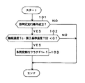
初めに仮判定処理について説明する。仮判定処理は、図2に示す仮判定処理ルーチンに従って実行される。図2に示す仮判定処理ルーチンは、ECU30のROMに予め記憶されており、所定時間毎に繰り返し実行されるルーチンである。
【0047】
<ステップ101>
仮判定処理ルーチンでは、ECU100は、まずステップ101において、仮判定実行条件が成立しているか否かを判定する。ここで、仮判定実行条件の成立要件は、エンジン1の運転状態が定常状態にあり、且つ、その定常状態が予め設定した規定時間継続していることである。エンジン1の定常状態とは、エンジン負荷及びエンジン回転数等がほぼ一定な運転状態をいい、アイドル運転状態は定常状態に含まれる。エンジン1が定常状態でない場合には、入ガス温センサ31で検出される入ガス温度Tgiも触媒温センサ32で検出される触媒温度Tcも不安定であり、正しい劣化判定を行うことができない。そこで、ステップ101で否定判定した場合には、ECU100は、この仮判定処理ルーチンを一旦終了する。
【0048】
<ステップ102>
ステップ101において肯定判定した場合には、ECU100は、ステップ102に進み、触媒温センサ31で検出した触媒温度Tcと第2の基準温度T02の温度差△Tpre=Tc−T02を演算し、この温度差△Tpreが負か否か判定する。ここで、第2の基準温度T02は、本判定の実行時期か否かを判定する基準値となるものであり、入ガス温センサ31および触媒温センサ32の測定精度などを考慮して予め設定し、ECU100のROMに予め記憶しておく。
【0049】
この第2の基準温度T02は、入ガス温度Tgiから推定したNOx触媒10が完全に劣化したときの触媒温度に設定することができ、この実施の形態のように定常な運転状態のときに仮判定処理を実行する場合には、第2の基準温度T02を入ガス温度Tgiそのものとすることもできる。
【0050】
<ステップ103>
ステップ102において肯定判定した場合には、本判定処理を実行する時期であるので、ECU100は、ステップ103に進み、本判定実行フラグF1を「1」とした後、この仮判定処理ルーチンを一旦終了する。
一方、ステップ102において否定判定した場合には、まだ本判定処理を実行する時期ではないので、ECU100は、この仮判定処理ルーチンを一旦終了する。
【0051】
尚、この実施の形態においては、仮判定処理ルーチンのうちステップ102をECU100が実行することにより、本発明における温度予備比較手段が実現される。
【0052】
次に、本判定処理について説明する。本判定処理は、図3に示す本判定処理ルーチンに従って実行される。図3に示す本判定処理ルーチンは、ECU30のROMに予め記憶されており、所定時間毎に繰り返し実行されるルーチンである。
【0053】
<ステップ201>
この本判定処理ルーチンでは、ECU100は、ステップ201において、触媒劣化フラグF2が「0」か否か判定する。この触媒劣化フラグF2は、本判定処理においてNOx触媒10が劣化していると判定されたときに「1」を立てるフラグであり、初期値は「0」である。
【0054】
<ステップ202>
ステップ201において肯定判定した場合には、ECU100は、ステップ202に進み、本判定実行フラグF1が「1」か否か判定する。ステップ202において否定判定した場合には、ECU100は、この本判定処理ルーチンを一旦終了する。
【0055】
<ステップ203>
ステップ202において肯定判定した場合には、ECU100は、ステップ203に進み、本判定実行条件が成立しているか否かを判定する。ここで、本判定実行条件の成立要件は、エンジン1の運転状態が定常状態にあり、且つ、その定常状態が予め設定した規定時間継続していることである。エンジン1の定常状態とは、エンジン負荷及びエンジン回転数等がほぼ一定な運転状態をいい、アイドル運転状態は定常状態に含まれる。エンジン1が定常状態でない場合には、入ガス温センサ31で検出される入ガス温度Tgiも触媒温センサ32で検出される触媒温度Tcも不安定であり、正しい劣化判定を行うことができない。そこで、ステップ203で否定判定した場合には、ECU100は、この本判定処理ルーチンを一旦終了する。
【0056】
<ステップ204>
ステップ203において肯定判定した場合には、ECU100は、ステップ204に進み、劣化判定副噴射を実行して大量の還元剤をNOx触媒10に供給する。ここで、劣化判定副噴射のときの副噴射量は、NOx浄化副噴射のときの副噴射量の所定倍とし、その倍率は予め設定されてECU100のROMに記憶されている。
【0057】
尚、劣化判定副噴射の副噴射量が大量なため、副噴射により増大した排気ガス中のHCの総てをNOx触媒10で浄化することができない虞れもあるが、この実施の形態では、NOx触媒10の下流に酸化触媒20が設けられているので、劣化判定副噴射時にNOx触媒10を通過したHCは酸化触媒20によって浄化される。したがって、本判定処理を実行している間もHCエミッションが悪化することはない。
【0058】
<ステップ205>
次に、ECU100は、ステップ204からステップ205に進み、劣化判定副噴射を開始してからの経過時間が予め設定した規定時間経過したか否か判定する。これは、劣化判定副噴射の実行開始から前記規定時間が経過しないと、劣化判定副噴射によるNOx触媒10の昇温の影響が出ないからである。
【0059】
ステップ205において否定判定した場合には、ECU100は、この本判定処理ルーチンを一旦終了する。そして、この本判定処理ルーチンを次回実行したときに、ECU100が、ステップ203で肯定判定した場合には、ステップ204に進んで劣化判定副噴射を実行し、したがって劣化判定副噴射が継続され、ECU100は、ステップ205において劣化判定副噴射を開始してから規定時間経過したか否か判定する。一方、この本判定処理ルーチンを次回実行したときに、エンジン1の運転状態が定常状態から脱したため、ECU100が、ステップ203で否定判定した場合には、ECU100は、この本判定処理ルーチンを一旦終了する。したがって、この場合には、劣化判定副噴射を一旦終了することになり、ステップ205において判定の基礎となる劣化判定副噴射を開始してからの経過時間はリセットされて「0」になる。
【0060】
<ステップ206>
劣化判定副噴射を開始してから規定時間が経過した場合には、即ち、ステップ205において肯定判定した場合には、ECU100は、ステップ206に進み、触媒温センサ31で検出した触媒温度Tcと第1の基準温度T01の温度差△T=Tc−T01を演算し、この温度差△Tが負か否か判定する。ここで、第1の基準温度T01は、NOx触媒10が完全に劣化したか否かを判定する基準値となるものであり、入ガス温センサ31および触媒温センサ32の測定精度などを考慮して予め設定し、ECU100のROMに予め記憶しておく。
【0061】
この第1の基準温度T01は、入ガス温度Tgiから推定したNOx触媒10が完全に劣化したときの触媒温度に設定することができ、この実施の形態のように定常な運転状態のときに本判定処理を実行する場合には、第1の基準温度T01を入ガス温度Tgiそのものとすることもできる。
【0062】
<ステップ207、ステップ208>
ステップ206において肯定判定した場合には、ECU100は、ステップ207に進み、NOx触媒10が劣化したものと判定し、ステップ208に進んで、触媒劣化フラグF2を「1」とする。
【0063】
<ステップ209>
次に、ECU100は、ステップ208からステップ209に進み、ダイアグランプを点灯するとともに、これ以後のNOx浄化副噴射の実行を禁止する。NOx浄化副噴射の実行を禁止する理由は、NOx触媒10が完全に劣化した状態で燃料の副噴射を実行しても、副噴射により生じたHCはNOx触媒10で浄化されずにNOx触媒10を通過するだけであり、HCエミッションを悪化させるとともに燃料を浪費することになるからである。尚、NOx浄化副噴射を実行しないときにも、排気ガス中にはHCおよびCOが含まれているが、これらはNOx触媒10の下流に設けられた酸化触媒20によって浄化される。
ステップ209の処理を実行した後、ECU100は、この本判定処理ルーチンを一旦終了する。
【0064】
尚、触媒劣化フラグF2は、図示しないリセットボタンを押さない限り「0」にすることはできない。したがって、ステップ208において触媒劣化フラグF2を「1」とした後は、この本判定処理ルーチンを次回以降実行したときに、ECU100は、ステップ201において否定判定をしてステップ209に進み、NOx浄化副噴射の実行禁止を継続することになる。
【0065】
<ステップ210>
一方、ステップ206において否定判定した場合には、NOx触媒10は完全な劣化ではないので、ECU100は、ステップ210に進み、触媒温センサ31で検出した触媒温度Tcと第1の基準温度T01の温度差△Tが予め設定した規定温度差△t(>0)よりも小さいか否かを判定する。規定温度△tは、NOx触媒10の劣化の程度が、NOx浄化副噴射の副噴射量を減少補正する必要がある程度まで進行しているか否かを判定する基準値となるものであり、入ガス温センサ31および触媒温センサ32の測定精度などを考慮して予め設定し、ECU100のROMに予め記憶しておく。
【0066】
<ステップ211>
ステップ210で肯定判定した場合には、即ち、触媒温度Tcと第1の基準温度T01の温度差△Tが規定温度差△tよりも小さい場合には、ECU100は、NOx触媒10は完全劣化ではないがある程度劣化が進行していると判定し、ステップ211に進んで、温度差△Tの大きさに応じて(換言すれば、劣化の程度に応じて)、これ以降のNOx浄化副噴射時の副噴射量の補正処理を実行する。
【0067】
NOx浄化副噴射時の副噴射量の補正処理は、図4に示すような副噴射量補正マップを参照して、温度差△Tに対応する補正係数kを演算し、NOx浄化副噴射の基本副噴射量Qp0にこの補正係数kを乗じて、補正後の副噴射量Qpを演算する。 Qp=k・Qp0
【0068】
図4に示す副噴射量補正マップは、予め実験を行い、NOx触媒10の劣化の程度に応じて排気エミッションを悪化させないNOx浄化副噴射に最適な副噴射量を求め、これを基に補正係数kを求めてマップ化したものであり、ECU100のROMに予め記憶させておく。
【0069】
この副噴射量補正マップについて説明すると、触媒温度Tcが第1の基準温度T01に近付いて温度差△Tが小さくなるほどNOx触媒10の劣化が進行していることを意味し、補正係数kが小さいほど副噴射量が少なくなることを意味しており、したがって、NOx触媒10の劣化が進行するにしたがって副噴射量を減少補正することになる。
【0070】
ステップ211において副噴射量の補正処理の実行を終了した後、ECU100は、ステップ212に進んで、本判定実行フラグF1を「0」にして、この本判定処理ルーチンを一旦終了する。
【0071】
一方、ステップ210で否定判定した場合には、即ち、触媒温度Tcと第1の基準温度T01の温度差△Tが規定温度差△t以上である場合には、NOx触媒10は劣化していないと判定されて、ECU100は、ステップ212に進んで、本判定実行フラグF1を「0」にし、この本判定処理ルーチンを一旦終了する。
【0072】
このように、この実施の形態における内燃機関の排気浄化装置においては、NOx触媒10の劣化判定を高精度に行うことができ、また、劣化の程度に応じて副噴射量を減少補正しているので、劣化の進行に伴ってHCエミッションが悪化するのを防止することができるとともに、燃料の浪費を防止する。
【0073】
尚、この実施の形態においては、前述した本判定処理ルーチンのうちステップ206をECU100が実行することにより、本発明における温度比較手段が実現される。また、本判定処理ルーチンのうちステップ206及びステップ207をECU100が実行することにより、本発明における劣化判定手段が実現される。さらに、本判定処理ルーチンのうちステップ211をECU100が実行することにより、本発明における供給量補正手段が実現される。
【0074】
〔他の実施の形態〕
前述の実施の形態では、触媒温センサ32で検出したNOx触媒10の触媒温度と入ガス温センサ31で検出した入ガス温度との比較値(この実施の形態では差)に基づいて、NOx触媒10が劣化したか否かの判定を行ったり、NOx浄化副噴射の副噴射量の補正処理を行ったりしたが、触媒温センサ32を設ける代わりに、図5に示すように、ケーシング11の下流に、NOx触媒10の下流の排気ガス温度を検出する出ガス温センサ(温度検出手段)33を設けて、出ガス温センサ33で検出した出ガス温度を前記触媒温度の代わりにして、前記劣化判定や副噴射量の補正処理を行うことも可能である。
【0075】
前述の実施の形態では、NOx触媒10に流入する排気ガスの温度、即ち入ガス温度を入ガス温センサ31で実測しているが、入ガス温度はエンジン1の運転状態から推定可能であるので、エンジンの運転状態と入ガス温度とを対応させたマップを予めECU100のROMに記憶させておき、このマップを参照して入ガス温度を推定するようにしてもよく、推定した入ガス温度を、第1の基準温度T01あるいは第2の基準温度T02とすることも可能である。
【0076】
前述の実施の形態では、NOx触媒10に還元剤を供給する還元剤供給手段として、膨張行程あるいは排気行程で燃料を燃焼室2に供給する副噴射を採用したが、これに代えて、NOx触媒10よりも上流の排気通路に還元剤を供給する還元剤供給装置を採用することも可能である。
【0077】
また、前述の実施の形態では、内燃機関をディーゼルエンジンとしたが、本発明の内燃機関の排気浄化装置はガソリンエンジンにも適用可能である。内燃機関がガソリンエンジンの場合には、内燃機関の燃焼室に供給する混合気の空燃比を理論空燃比またはリッチ空燃比にして燃焼することにより排気ガスの空燃比を理論空燃比またはリッチ空燃比にして、NOx触媒10に還元剤としてのHCを供給するようにしてもよく、その場合には、還元剤供給手段は空燃比制御手段によって実現される。
【0078】
前述の実施の形態では、NOx触媒を選択還元型NOx触媒としたが、本発明の内燃機関の排気浄化装置はNOx触媒を吸蔵還元型NOx触媒とした場合にも成立する。吸蔵還元型NOx触媒は、流入する排気ガスの空燃比がリーンのときはNOxを吸収し、流入する排気ガス中の酸素濃度が低下すると吸収したNOxを放出しN2に還元する触媒であり、吸蔵還元型NOx触媒に吸収されたNOxを放出し還元するために適宜の間隔で吸蔵還元型NOx触媒に還元剤(HC)を供給する必要がある。また、この吸蔵還元型NOx触媒を長期に使用していると該触媒がSOxによる被毒を受けてNOx浄化率が低下するので、SOx被毒がある程度進行したときに吸蔵還元型NOx触媒をSOx被毒から回復するための再生処理を行う必要がある。この再生処理には、NOxを放出・還元するために供給するときよりも大量の還元剤を吸蔵還元型NOx触媒に供給する必要がある。したがって、NOx触媒を吸蔵還元型NOx触媒とした場合には、吸蔵還元型NOx触媒からNOxを放出・還元するために還元剤を該触媒に供給しているときを「通常時」とし、吸蔵還元型NOx触媒を再生処理するために還元剤を該触媒に通常時よりも大量に供給しているときに本判定を実行することができる。
【0079】
【発明の効果】
本発明に係る内燃機関の排気浄化装置によれば、希薄燃焼運転可能な内燃機関の排気通路に設けられたNOx触媒と、前記NOx触媒に還元剤を供給する還元剤供給手段と、前記NOx触媒の触媒温度あるいは前記NOx触媒の出口の排気ガス温度を検出する温度検出手段と、前記還元剤供給手段によって通常時の供給量よりも大量の還元剤を前記NOx触媒に供給したときに前記温度検出手段により検出した温度と第1の基準温度とを比較する温度比較手段と、前記温度比較手段の比較結果に基づいて前記NOx触媒が劣化しているか否かを判定する劣化判定手段と、を備えることにより、NOx触媒が劣化したか否かを高精度で判定することができるという優れた効果が奏される。
【0080】
また、本発明に係る内燃機関の排気浄化装置によれば、希薄燃焼運転可能な内燃機関の排気通路に設けられたNOx触媒と、前記NOx触媒に還元剤を供給する還元剤供給手段と、前記NOx触媒の触媒温度あるいは前記NOx触媒の出口の排気ガス温度を検出する温度検出手段と、前記還元剤供給手段によって通常時の供給量よりも大量の還元剤を前記NOx触媒に供給したときに前記温度検出手段により検出した温度と第1の基準温度とを比較する温度比較手段と、前記温度比較手段の比較結果に基づいて前記NOx触媒への通常時の還元剤供給量を補正する供給量補正手段と、を備えることにより、NOx触媒の劣化の程度に応じて通常時の還元剤供給量を補正することができ、NOx触媒の劣化の進行に伴うエミッションの悪化を防止することができるとともに、燃料の浪費を防止することができるという優れた効果が奏される。
【0081】
また、前記還元剤供給手段によって通常時の供給量の還元剤を前記NOx触媒に供給したときに前記温度検出手段により検出した温度と第2の基準温度とを比較する温度予備比較手段を備え、前記温度予備比較手段の比較結果に基づいて前記温度比較手段による比較処理を実行するか否かを決定するようにした場合には、温度比較手段による比較処理の実行時期を最適に制御することができる。
【0082】
前記還元剤供給手段を、前記内燃機関の気筒内に燃料を副噴射する副噴射手段により構成した場合には、劣化判定処理や副噴射量補正処理のための専用の還元剤供給手段を新たに設ける必要がなく、装置構成を簡略化することができる。
【図面の簡単な説明】
【図1】本発明に係る内燃機関の排気浄化装置の一実施の形態の概略構成図である。
【図2】前記実施の形態におけるNOx触媒の劣化判定のための仮判定処理ルーチンを示すフローチャートである。
【図3】前記実施の形態におけるNOx触媒の劣化判定のための本判定処理ルーチンを示すフローチャートである。
【図4】前記実施の形態における副噴射量補正マップの一例である。
【図5】本発明に係る内燃機関の排気浄化装置の別の実施の形態における要部構成図である。
【符号の説明】
1 ディーゼルエンジン
2 燃焼室
5 燃料噴射弁(還元剤供給手段)
8 排気管(排気通路)
10 選択還元型NOx触媒(NOx触媒)
20 酸化触媒
31 入ガス温センサ
32 触媒温センサ(温度検出手段)
33 出ガス温センサ(温度検出手段)
100 ECU(温度比較手段、劣化判定手段、供給量補正手段、温度予備比較手段)[0001]
BACKGROUND OF THE INVENTION
The present invention relates to an exhaust gas purification device that purifies exhaust gas discharged from an internal combustion engine capable of lean combustion operation, and particularly relates to an exhaust gas purification device that can purify NOx in the exhaust gas with a catalyst.
[0002]
[Prior art]
As a means for reducing the amount of harmful components in the exhaust gas discharged from the internal combustion engine to the atmosphere, there is a system for purifying the harmful components using the oxidizing or reducing action of a catalyst.
[0003]
Recent improvements in catalyst performance have led to remarkable improvements in catalyst performance, and it has become possible to realize a catalytic device with high purification performance despite its small size. As a result, in recent years, exhaust gas purification devices incorporating a catalyst have been widely used as an exhaust gas purification system for purifying exhaust gas of a vehicle internal combustion engine.
[0004]
Currently, exhaust gas purification catalysts in practical use include oxidation catalysts, three-way catalysts, NOx catalysts, etc., and these catalysts can be used as combustion forms and air-fuel ratios of internal combustion engines or harmful substances to be purified. It is properly used according to the type.
[0005]
Of these catalysts, NOx catalysts are widely used as catalysts capable of purifying exhaust gas exhausted from an internal combustion engine capable of lean burn operation. As NOx catalysts, selective reduction type NOx catalysts and storage reduction type NOx catalysts are used. There is. The selective reduction type NOx catalyst refers to a catalyst that reduces or decomposes NOx in the presence of hydrocarbon (HC) in an oxygen-excess atmosphere, while the occlusion reduction type NOx catalyst refers to a lean air-fuel ratio of the inflowing exhaust gas. In this case, NOx is absorbed, and when the oxygen concentration in the inflowing exhaust gas decreases, the absorbed NOx is released and N2Refers to a catalyst that reduces to These NOx catalysts have an oxidizing action for oxidizing and purifying HC in exhaust gas and a reducing action for reducing and purifying NOx in exhaust gas.
[0006]
Generally, when a catalyst is used for a long period of time, so-called deterioration occurs in which the oxidation action and reduction action of the catalyst decline. If the above NOx catalyst is used for a long time, if it is used for a long period of time, the HC purification capacity may be reduced due to the deterioration of the oxidation action (this may be distinguished from HC deterioration), or the NOx reduction due to the reduction of the reduction action. The purification ability is reduced (this may be distinguished from NOx deterioration). If the deteriorated NOx catalyst is continuously used, harmful substances in the exhaust gas cannot be completely purified, and the exhaust gas containing the harmful substances may be discharged into the atmosphere. Therefore, it is necessary to take measures such as replacement for such a NOx catalyst having a reduced purification capability, and for that purpose, management of the purification capability of the catalyst (in other words, determination of deterioration of the catalyst) is extremely important.
[0007]
As a catalyst deterioration determination technique, for example, there is one disclosed in JP-A-5-31024. In the technique described in this publication, attention is paid to heat generation when the catalyst performs its function, and deterioration of the catalyst is determined based on the temperature change.
[0008]
More specifically, temperature sensors for detecting the exhaust gas temperature are provided upstream and downstream of the NOx catalyst provided in the exhaust passage of the internal combustion engine, and the exhaust gas temperature on the upstream side and the exhaust gas on the downstream side in the normal operation state of the internal combustion engine are provided. Calculate the temperature difference of gas temperature. When the NOx catalyst functions normally and purifies HC, CO, and NOx, the NOx catalyst generates heat, so that the downstream exhaust gas temperature rises higher than the upstream exhaust gas temperature. However, since the amount of heat generated in the NOx catalyst decreases as the deterioration of the NOx catalyst progresses, the downstream exhaust gas temperature approaches the upstream exhaust gas temperature. That is, as the deterioration of the NOx catalyst proceeds, the difference between the downstream exhaust gas temperature and the upstream exhaust gas temperature becomes smaller. Accordingly, when the temperature difference between the exhaust gas temperature on the downstream side and the exhaust gas temperature on the upstream side becomes equal to or less than a preset threshold value, it is determined that the NOx catalyst has deteriorated.
[0009]
[Problems to be solved by the invention]
In the conventional catalyst deterioration determination technique described above, the deterioration determination is performed based on the difference in exhaust gas temperature between the upstream and downstream of the NOx catalyst in the normal operation state of the internal combustion engine. Originally, in the normal operation state of the internal combustion engine, NOx Even when the catalyst is not deteriorated, the amount of heat generated in the NOx catalyst is small, so that the difference in exhaust gas temperature between the upstream and downstream is also small. As described above, since the deterioration determination is performed based on the temperature difference which is a small value even in the normal state, there is a problem that the determination accuracy is low.
[0010]
The present invention has been made in view of the above-described problems of the prior art, and the problem to be solved by the present invention is an internal combustion engine that can determine deterioration of a catalyst with high accuracy while having a simple structure. An object of the present invention is to provide an exhaust purification device.
Another object of the present invention is to provide an exhaust emission control device for an internal combustion engine that can optimally control the amount of reducing agent supplied to the NOx catalyst in accordance with the degree of catalyst deterioration with a simple structure. is there.
[0011]
[Means for Solving the Problems]
In order to solve the above problems, the invention according to the present application employs the following means.
(1) An exhaust emission control device for an internal combustion engine according to a first aspect of the present application is a NOx catalyst provided in an exhaust passage of an internal combustion engine capable of lean combustion operation, and a reducing agent supply for supplying a reducing agent to the NOx catalyst. Means, a temperature detecting means for detecting the catalyst temperature of the NOx catalyst or the exhaust gas temperature at the outlet of the NOx catalyst, and a reducing agent supply means for supplying a reducing agent in a larger amount than a normal supply amount to the NOx catalyst. A temperature comparison unit that compares the temperature detected by the temperature detection unit with a first reference temperature, and a deterioration that determines whether or not the NOx catalyst has deteriorated based on a comparison result of the temperature comparison unit Determining means.
[0012]
When a larger amount of reducing agent than the normal supply amount is supplied to the NOx catalyst by the reducing agent supply means, the calorific value in the NOx catalyst is the normal reduction unless the NOx catalyst is completely degraded and loses its catalytic function. It becomes larger than the amount of agent supply. Therefore, the comparison result (comparison value) obtained by comparing the temperature detected by the temperature detection means at this time (the catalyst temperature or the exhaust gas temperature at the catalyst outlet) with the first reference temperature is the normal reducing agent supply amount. It becomes clearer than the comparison result (comparison value). Since the deterioration determination means determines whether or not the NOx catalyst has deteriorated based on this obvious comparison result obtained by the temperature comparison means, the deterioration determination accuracy is high.
[0013]
(2) An exhaust emission control device for an internal combustion engine according to a second aspect of the present application is a NOx catalyst provided in an exhaust passage of an internal combustion engine capable of lean combustion operation, and a reducing agent supply for supplying a reducing agent to the NOx catalyst Means, a temperature detecting means for detecting the catalyst temperature of the NOx catalyst or the exhaust gas temperature at the outlet of the NOx catalyst, and a reducing agent supply means for supplying a reducing agent in a larger amount than a normal supply amount to the NOx catalyst. A temperature comparison unit that compares the temperature detected by the temperature detection unit with the first reference temperature, and a normal reducing agent supply amount to the NOx catalyst is corrected based on a comparison result of the temperature comparison unit. Supply amount correcting means.
[0014]
When a larger amount of reducing agent than the normal supply amount is supplied to the NOx catalyst by the reducing agent supply means, the calorific value in the NOx catalyst is the normal reduction unless the NOx catalyst is completely degraded and loses its catalytic function. It becomes larger than the amount of agent supply. Therefore, the comparison result (comparison value) obtained by comparing the temperature detected by the temperature detection means at this time (the catalyst temperature or the exhaust gas temperature at the catalyst outlet) with the first reference temperature is the normal reducing agent supply amount. It becomes clearer than the comparison result (comparison value).
[0015]
As the deterioration of the NOx catalyst progresses, the purification performance decreases. Therefore, if the normal amount of reducing agent supplied before deterioration is supplied after the deterioration has progressed, the reducing agent becomes excessive and passes through the NOx catalyst, resulting in a worse emission. End up. Therefore, in the exhaust purification apparatus of the second aspect of the invention, the supply amount correcting means corrects the normal reducing agent supply amount to the NOx catalyst based on the obvious comparison result obtained by the temperature comparing means. As a result, it is possible to prevent the emission from deteriorating as the NOx catalyst deteriorates. At the same time, waste of the reducing agent can be prevented.
[0016]
In the first and second inventions described above, examples of the internal combustion engine include a diesel engine or a gasoline engine capable of lean combustion.
In the first invention and the second invention described above, examples of the NOx catalyst include a selective reduction type NOx catalyst and an occlusion reduction type NOx catalyst.
[0017]
The selective reduction type NOx catalyst is a catalyst that reduces or decomposes NOx in the presence of hydrocarbons in an oxygen-excess atmosphere. For example, a catalyst in which a transition metal such as Cu is ion-exchanged on zeolite, supported on zeolite or alumina. A catalyst carrying a noble metal is included.
[0018]
The NOx storage reduction catalyst absorbs NOx when the air-fuel ratio of the exhaust gas flowing into the catalyst is lean, and releases the absorbed NOx when the oxygen concentration in the flowing exhaust gas decreases and N2Refers to a catalyst that reduces to The NOx storage reduction catalyst uses, for example, alumina as a carrier, and an alkaline metal such as potassium K, sodium Na, lithium Li, and cesium Cs, an alkaline earth such as barium Ba and calcium Ca, lanthanum La, and the like. At least one selected from rare earths such as yttrium Y and a noble metal such as platinum Pt are supported.
[0019]
In the first and second inventions described above, hydrocarbon (HC) is suitable as the reducing agent.
In the first and second inventions described above, the reducing agent supply means can be constituted by sub-injection means for sub-injecting fuel into the cylinder in the expansion stroke or exhaust stroke, or the cylinder of the internal combustion engine and the NOx. A reducing agent supply device that supplies a reducing agent to the exhaust passage between the catalysts can also be used. Further, in the case of a gasoline engine that can be operated at a stoichiometric air-fuel ratio or a rich air-fuel ratio, the air-fuel ratio of the air-fuel mixture supplied to the combustion chamber is set to the stoichiometric air-fuel ratio or rich air-fuel ratio, and the air-fuel ratio of the exhaust gas is stoichiometrically reduced. Since the reducing agent can be supplied to the NOx catalyst by setting the fuel ratio or the rich air-fuel ratio, in this case, the reducing agent supply means can be constituted by the air-fuel ratio control means.
[0020]
Further, the supply of the reducing agent by the reducing agent supply means may be continuous supply or intermittent supply. Which of the supply methods is adopted depends on the type of NOx catalyst used and the exhaust purification device. Determined by the whole system.
In the first and second inventions described above, the temperature detecting means can be constituted by a temperature sensor.
[0021]
In the first and second inventions described above, the normal reducing agent supply amount refers to the reducing agent supply amount required for purifying NOx in the exhaust gas. On the other hand, a large amount of reducing agent supply amount is a reducing agent supply amount several times or more (for example, including 4 to 5 times, or several tens or several hundreds times) of the normal reducing agent supply amount. Say.
[0022]
In the first and second inventions described above, the comparison result of the temperature comparison means can be expressed by the difference between the temperature detected by the temperature detection means and the first reference temperature, and is detected by the temperature detection means. It is also possible to represent the quotient of the measured temperature and the first reference temperature.
[0023]
In the first invention described above, when it is determined that the NOx catalyst has deteriorated when the HC purification capacity of the NOx catalyst has almost completely disappeared, the first reference temperature flows into the
[0024]
In the above-described second invention, the supply amount correcting means corrects the normal reducing agent supply amount to the NOx catalyst as the temperature detected by the temperature detecting means approaches the first reference temperature. Is preferred.
[0025]
In the first and second inventions described above, the temperature detected by the temperature detecting means when the normal amount of reducing agent is supplied to the NOx catalyst by the reducing agent supply means and the second reference. A temperature preliminary comparing means for comparing the temperature may be provided, and it may be determined whether or not to execute the comparison process by the temperature comparing means based on the comparison result of the temperature preliminary comparing means. This is one method for determining the execution timing of the NOx catalyst deterioration determination processing and the execution timing of the reducing agent supply amount correction processing. However, the method for determining the execution time is not limited to this method. For example, the execution time may be determined when the operating time of the internal combustion engine reaches a predetermined time, or the travel distance may be set to the predetermined distance. The time when the time has been reached may be determined as the execution time.
[0026]
The comparison result of the temperature preliminary comparison means can be expressed by the difference between the temperature detected by the temperature preliminary detection means and the second reference temperature, and is the quotient of the temperature detected by the temperature detection means and the second reference temperature. It can also be expressed.
[0027]
DETAILED DESCRIPTION OF THE INVENTION
Hereinafter, an embodiment of an exhaust gas purification apparatus for an internal combustion engine according to the present invention will be described with reference to the drawings of FIGS. In addition, embodiment described below is the aspect which applied the exhaust gas purification apparatus which concerns on this invention to the diesel engine for vehicles as an internal combustion engine.
[0028]
FIG. 1 is a diagram showing an overall configuration of an embodiment of an exhaust gas purification apparatus for an internal combustion engine. The
[0029]
Further, the
[0030]
Exhaust gas generated in the
[0031]
The selective reduction type NOx catalyst refers to a catalyst that reduces or decomposes NOx in the presence of hydrocarbon (HC) in an oxygen-excess atmosphere. For example, a catalyst in which a transition metal such as Cu is ion-exchanged on a zeolite, and a zeolite Alternatively, a catalyst having a noble metal supported on alumina is included.
[0032]
An inlet gas temperature sensor 31 for outputting an output signal corresponding to the temperature of exhaust gas (hereinafter referred to as inlet gas) flowing into the
[0033]
A catalyst temperature sensor (temperature detection means) 32 that outputs an output signal corresponding to the temperature (catalyst temperature) of the
[0034]
The
[0035]
For these controls, an input signal from the accelerator opening sensor 51 and an input signal from the crank angle sensor 52 are input to the input port of the
[0036]
In order to purify NOx in the exhaust gas with the selective reduction
[0037]
Here, the
[0038]
Next, the operation of the exhaust gas purification apparatus for an internal combustion engine in this embodiment will be described.
In this internal combustion engine, when the sub-injection execution condition such as the catalyst temperature of the
This normal sub-injection is referred to as “NOx purification sub-injection” in the following description. The sub-injection amount in the NOx purification sub-injection corresponds to “normal reducing agent supply amount”. When the
[0039]
When the
[0040]
However, as the deterioration of the
[0041]
However, in the exhaust emission control device of this embodiment, in order to increase the accuracy of the deterioration determination, when executing the NOx deterioration determination process, it is several times the normal amount of reducing agent supply (for example, 4 to 5 times). A corresponding large amount of reducing agent was supplied to the
[0042]
When the amount of reducing agent supplied to the
[0043]
The execution time of the main determination can be, for example, when the travel distance of the vehicle reaches a predetermined distance set in advance or when the driving time of the vehicle reaches a predetermined time set in advance. In this form, the
[0044]
Further, as the deterioration of the
[0045]
Therefore, in this embodiment, the main determination process is executed, and as a result, when the temperature difference ΔT between the catalyst temperature Tc and the input gas temperature Tgi is equal to or greater than a predetermined temperature difference, the temperature difference ΔT is increased. Accordingly, the sub-injection amount in the NOx purification sub-injection is corrected to decrease. In other words, the sub-injection amount in the NOx purification sub-injection is corrected to decrease according to the degree of deterioration of the
[0046]
Next, a temporary determination process and a main determination process for determining the deterioration of the
First, the provisional determination process will be described. The temporary determination process is executed according to the temporary determination process routine shown in FIG. The temporary determination processing routine shown in FIG. 2 is a routine that is stored in advance in the ROM of the ECU 30 and is repeatedly executed at predetermined time intervals.
[0047]
<Step 101>
In the temporary determination processing routine, the
[0048]
<Step 102>
If an affirmative determination is made in
[0049]
This second reference temperature T02Can be set to the catalyst temperature when the
[0050]
<Step 103>
If an affirmative determination is made in
On the other hand, if a negative determination is made in
[0051]
In this embodiment, the temperature preliminary comparing means in the present invention is realized by the
[0052]
Next, this determination process will be described. The main determination process is executed according to the main determination process routine shown in FIG. The determination processing routine shown in FIG. 3 is a routine that is stored in advance in the ROM of the ECU 30 and is repeatedly executed at predetermined time intervals.
[0053]
<Step 201>
In this determination processing routine, the
[0054]
<Step 202>
If an affirmative determination is made in
[0055]
<Step 203>
If the determination in
[0056]
<Step 204>
If an affirmative determination is made in
[0057]
Incidentally, since the sub injection amount of the deterioration determination sub injection is large, there is a possibility that all of the HC in the exhaust gas increased by the sub injection cannot be purified by the
[0058]
<Step 205>
Next, the
[0059]
If a negative determination is made in
[0060]
<Step 206>
If the specified time has elapsed since the start of the deterioration determination sub-injection, that is, if an affirmative determination is made in
[0061]
This first reference temperature T01Can be set to the catalyst temperature when the
[0062]
<Step 207,
If an affirmative determination is made in
[0063]
<Step 209>
Next, the
After executing the processing of
[0064]
The catalyst deterioration flag F2Cannot be set to “0” unless a reset button (not shown) is pressed. Therefore, in
[0065]
<Step 210>
On the other hand, if a negative determination is made in
[0066]
<Step 211>
If the determination in
[0067]
The correction process of the sub-injection amount at the time of NOx purification sub-injection is performed by referring to a sub-injection amount correction map as shown in FIG. Sub injection amount Qp0Is multiplied by the correction coefficient k to calculate the corrected sub-injection amount Qp. Qp = k · Qp0
[0068]
The sub-injection amount correction map shown in FIG. 4 is obtained by conducting an experiment in advance and obtaining an optimal sub-injection amount for NOx purification sub-injection that does not deteriorate exhaust emission according to the degree of deterioration of the
[0069]
This sub-injection amount correction map will be described. The catalyst temperature Tc approaches the first reference temperature T01 and the temperature difference ΔT decreases, meaning that the deterioration of the
[0070]
After completing the execution of the sub-injection amount correction process in step 211, the
[0071]
On the other hand, if a negative determination is made in
[0072]
As described above, in the exhaust gas purification apparatus for an internal combustion engine according to this embodiment, the deterioration determination of the
[0073]
In this embodiment, the
[0074]
[Other Embodiments]
In the above-described embodiment, the NOx catalyst is based on the comparison value (the difference in this embodiment) between the catalyst temperature of the
[0075]
In the above-described embodiment, the temperature of the exhaust gas flowing into the
[0076]
In the above-described embodiment, the sub-injection for supplying the fuel to the
[0077]
In the above-described embodiment, the internal combustion engine is a diesel engine. However, the exhaust gas purification apparatus for an internal combustion engine of the present invention can also be applied to a gasoline engine. When the internal combustion engine is a gasoline engine, the air-fuel ratio of the air-fuel mixture supplied to the combustion chamber of the internal combustion engine is burned with the stoichiometric air-fuel ratio or rich air-fuel ratio, so that the air-fuel ratio of the exhaust gas becomes the stoichiometric air-fuel ratio or rich air-fuel ratio. Thus, HC as a reducing agent may be supplied to the
[0078]
In the above-described embodiment, the NOx catalyst is a selective reduction type NOx catalyst. However, the exhaust gas purification apparatus for an internal combustion engine according to the present invention is also applicable when the NOx catalyst is a storage reduction type NOx catalyst. The NOx storage reduction catalyst absorbs NOx when the air-fuel ratio of the inflowing exhaust gas is lean, and releases the absorbed NOx when the oxygen concentration in the inflowing exhaust gas decreases and N2In order to release and reduce NOx absorbed in the NOx storage reduction catalyst, it is necessary to supply a reducing agent (HC) to the NOx storage reduction catalyst at an appropriate interval. Further, if this NOx storage reduction catalyst is used for a long period of time, the NOx purification rate decreases due to the catalyst being poisoned by SOx, so when the SOx poisoning proceeds to some extent, the NOx storage reduction catalyst is replaced with SOx. It is necessary to perform a regeneration process to recover from poisoning. In this regeneration process, it is necessary to supply a larger amount of reducing agent to the NOx storage reduction catalyst than when supplying NOx for release / reduction. Therefore, when the NOx catalyst is a storage reduction type NOx catalyst, the time when the reducing agent is supplied to the catalyst to release and reduce NOx from the storage reduction type NOx catalyst is referred to as “normal time”, and the storage reduction This determination can be executed when a large amount of reducing agent is supplied to the catalyst to regenerate the type NOx catalyst.
[0079]
【The invention's effect】
According to the exhaust gas purification apparatus for an internal combustion engine according to the present invention, a NOx catalyst provided in an exhaust passage of an internal combustion engine capable of lean combustion operation, a reducing agent supply means for supplying a reducing agent to the NOx catalyst, and the NOx catalyst Temperature detection means for detecting the catalyst temperature of the catalyst or the exhaust gas temperature at the outlet of the NOx catalyst, and the temperature detection when a larger amount of reducing agent than the normal supply amount is supplied to the NOx catalyst by the reducing agent supply means. Temperature comparison means for comparing the temperature detected by the means with a first reference temperature, and deterioration determination means for determining whether or not the NOx catalyst is deteriorated based on a comparison result of the temperature comparison means. As a result, it is possible to determine with high accuracy whether or not the NOx catalyst has deteriorated.
[0080]
According to the exhaust gas purification apparatus for an internal combustion engine according to the present invention, the NOx catalyst provided in the exhaust passage of the internal combustion engine capable of lean combustion operation, the reducing agent supply means for supplying the reducing agent to the NOx catalyst, The temperature detecting means for detecting the catalyst temperature of the NOx catalyst or the exhaust gas temperature at the outlet of the NOx catalyst, and when the reducing agent supply means supplies a larger amount of reducing agent than the normal supply amount to the NOx catalyst. A temperature comparison unit that compares the temperature detected by the temperature detection unit with the first reference temperature, and a supply amount correction that corrects a normal reducing agent supply amount to the NOx catalyst based on a comparison result of the temperature comparison unit. The amount of normal reducing agent supply can be corrected according to the degree of deterioration of the NOx catalyst, and the deterioration of emissions accompanying the progress of deterioration of the NOx catalyst can be prevented. It is possible to be achieved excellent effects that it is possible to prevent the waste of fuel.
[0081]
In addition, a temperature preliminary comparing means for comparing the temperature detected by the temperature detecting means with the second reference temperature when the normal amount of reducing agent is supplied to the NOx catalyst by the reducing agent supply means, When it is determined whether to execute the comparison process by the temperature comparison unit based on the comparison result of the temperature preliminary comparison unit, it is possible to optimally control the execution timing of the comparison process by the temperature comparison unit. it can.
[0082]
In the case where the reducing agent supply means is constituted by sub-injection means for sub-injecting fuel into the cylinder of the internal combustion engine, a dedicated reducing agent supply means for deterioration determination processing and sub-injection amount correction processing is newly provided. There is no need to provide it, and the apparatus configuration can be simplified.
[Brief description of the drawings]
FIG. 1 is a schematic configuration diagram of an embodiment of an exhaust gas purification apparatus for an internal combustion engine according to the present invention.
FIG. 2 is a flowchart showing a provisional determination processing routine for determining deterioration of the NOx catalyst in the embodiment.
FIG. 3 is a flowchart showing a main determination processing routine for determining deterioration of the NOx catalyst in the embodiment.
FIG. 4 is an example of a sub injection amount correction map in the embodiment.
FIG. 5 is a configuration diagram of a main part of another embodiment of the exhaust gas purification apparatus for an internal combustion engine according to the present invention.
[Explanation of symbols]
1 Diesel engine
2 Combustion chamber
5 Fuel injection valve (reducing agent supply means)
8 Exhaust pipe (exhaust passage)
10 Selective reduction type NOx catalyst (NOx catalyst)
20 Oxidation catalyst
31 Inlet gas temperature sensor
32 Catalyst temperature sensor (temperature detection means)
33 Outgas temperature sensor (temperature detection means)
100 ECU (temperature comparison means, deterioration determination means, supply amount correction means, temperature preliminary comparison means)
Claims (5)
前記NOx触媒に還元剤を供給する還元剤供給手段と、
前記NOx触媒の触媒温度あるいは前記NOx触媒の出口の排気ガス温度を検出する温度検出手段と、
前記還元剤供給手段によって通常時の供給量よりも大量の還元剤を前記NOx触媒に供給したときに前記温度検出手段により検出した温度と第1の基準温度とを比較する温度比較手段と、
前記温度比較手段の比較結果に基づいて前記NOx触媒が劣化しているか否かを判定する劣化判定手段と、
前記還元剤供給手段によって通常時の供給量の還元剤を前記NOx触媒に供給したときに前記温度検出手段により検出した温度と第2の基準温度とを比較する温度予備比較手段と、を備え、
前記温度予備比較手段の比較結果に基づいて前記温度比較手段による比較処理を実行するか否かを決定することを特徴とする内燃機関の排気浄化装置。A NOx catalyst provided in an exhaust passage of an internal combustion engine capable of lean combustion operation;
Reducing agent supply means for supplying a reducing agent to the NOx catalyst;
Temperature detecting means for detecting the catalyst temperature of the NOx catalyst or the exhaust gas temperature at the outlet of the NOx catalyst;
A temperature comparing means for comparing the temperature detected by the temperature detecting means with the first reference temperature when a larger amount of reducing agent than the normal supply amount is supplied to the NOx catalyst by the reducing agent supply means;
A deterioration determining means for determining whether or not the NOx catalyst is deteriorated based on a comparison result of the temperature comparing means;
A temperature preliminary comparing means for comparing a temperature detected by the temperature detecting means with a second reference temperature when a normal amount of reducing agent is supplied to the NOx catalyst by the reducing agent supply means;
An exhaust gas purification apparatus for an internal combustion engine, wherein whether or not to perform a comparison process by the temperature comparison means is determined based on a comparison result of the temperature preliminary comparison means .
前記NOx触媒に還元剤を供給する還元剤供給手段と、
前記NOx触媒の触媒温度あるいは前記NOx触媒の出口の排気ガス温度を検出する温度検出手段と、
前記還元剤供給手段によって通常時の供給量よりも大量の還元剤を前記NOx触媒に供給したときに前記温度検出手段により検出した温度と第1の基準温度とを比較する温度比較手段と、
前記温度比較手段の比較結果に基づいて前記NOx触媒への通常時の還元剤供給量を補正する供給量補正手段と、
前記還元剤供給手段によって通常時の供給量の還元剤を前記NOx触媒に供給したときに前記温度検出手段により検出した温度と第2の基準温度とを比較する温度予備比較手段と、を備え、
前記温度予備比較手段の比較結果に基づいて前記温度比較手段による比較処理を実行するか否かを決定することを特徴とする内燃機関の排気浄化装置。A NOx catalyst provided in an exhaust passage of an internal combustion engine capable of lean combustion operation;
Reducing agent supply means for supplying a reducing agent to the NOx catalyst;
Temperature detecting means for detecting the catalyst temperature of the NOx catalyst or the exhaust gas temperature at the outlet of the NOx catalyst;
A temperature comparing means for comparing the temperature detected by the temperature detecting means with the first reference temperature when a larger amount of reducing agent than the normal supply amount is supplied to the NOx catalyst by the reducing agent supply means;
A supply amount correcting means for correcting a normal reducing agent supply amount to the NOx catalyst based on a comparison result of the temperature comparing means;
A temperature preliminary comparing means for comparing a temperature detected by the temperature detecting means with a second reference temperature when a normal amount of reducing agent is supplied to the NOx catalyst by the reducing agent supply means;
An exhaust gas purification apparatus for an internal combustion engine, wherein whether or not to perform a comparison process by the temperature comparison means is determined based on a comparison result of the temperature preliminary comparison means .
Priority Applications (1)
| Application Number | Priority Date | Filing Date | Title |
|---|---|---|---|
| JP23405699A JP3552603B2 (en) | 1999-08-20 | 1999-08-20 | Exhaust gas purification device for internal combustion engine |
Applications Claiming Priority (1)
| Application Number | Priority Date | Filing Date | Title |
|---|---|---|---|
| JP23405699A JP3552603B2 (en) | 1999-08-20 | 1999-08-20 | Exhaust gas purification device for internal combustion engine |
Publications (2)
| Publication Number | Publication Date |
|---|---|
| JP2001059413A JP2001059413A (en) | 2001-03-06 |
| JP3552603B2 true JP3552603B2 (en) | 2004-08-11 |
Family
ID=16964899
Family Applications (1)
| Application Number | Title | Priority Date | Filing Date |
|---|---|---|---|
| JP23405699A Expired - Lifetime JP3552603B2 (en) | 1999-08-20 | 1999-08-20 | Exhaust gas purification device for internal combustion engine |
Country Status (1)
| Country | Link |
|---|---|
| JP (1) | JP3552603B2 (en) |
Families Citing this family (7)
| Publication number | Priority date | Publication date | Assignee | Title |
|---|---|---|---|---|
| DE19963903A1 (en) * | 1999-12-31 | 2001-07-12 | Bosch Gmbh Robert | Method for operating an internal combustion engine, in particular a motor vehicle |
| JP4507957B2 (en) * | 2005-04-06 | 2010-07-21 | トヨタ自動車株式会社 | Catalyst deterioration detection device for internal combustion engine |
| US8148290B2 (en) * | 2006-06-27 | 2012-04-03 | Basf Corporation | Diesel exhaust treatment system catalyst monitoring |
| KR101091627B1 (en) * | 2009-08-31 | 2011-12-08 | 기아자동차주식회사 | Exhaust system |
| KR101189238B1 (en) * | 2010-08-11 | 2012-10-09 | 기아자동차주식회사 | NOx Storage and Reduction Catalyst, Preparation Method thereof, and NOx Removing System Comprising the Same |
| JP5450319B2 (en) * | 2010-08-31 | 2014-03-26 | 日立Geニュークリア・エナジー株式会社 | How to monitor recombiner catalyst performance |
| DE102016107867A1 (en) | 2015-05-12 | 2016-11-17 | Denso Corporation | Exhaust emission control system and purification control device |
-
1999
- 1999-08-20 JP JP23405699A patent/JP3552603B2/en not_active Expired - Lifetime
Also Published As
| Publication number | Publication date |
|---|---|
| JP2001059413A (en) | 2001-03-06 |
Similar Documents
| Publication | Publication Date | Title |
|---|---|---|
| EP1793099B1 (en) | Method of exhaust gas purification and exhaust gas purification system | |
| US7963103B2 (en) | Exhaust gas purification method and system | |
| JP4415648B2 (en) | Sulfur purge control method and exhaust gas purification system | |
| US20100115924A1 (en) | METHOD OF CONTROLLING NOx PURIFICATION SYSTEM AND NOx PURIFICATION SYSTEM | |
| JP2009046992A (en) | Abnormality diagnostic system of nox sensor | |
| JP2004239218A (en) | Exhaust gas purging system of internal combustion engine | |
| US20140186220A1 (en) | Exhaust gas purification apparatus for an internal combustion engine | |
| EP3098423B1 (en) | Control apparatus for an internal combustion engine | |
| JP3613670B2 (en) | Exhaust gas purification device for internal combustion engine | |
| JP3624815B2 (en) | Exhaust gas purification device for internal combustion engine | |
| JP3552603B2 (en) | Exhaust gas purification device for internal combustion engine | |
| JP4935929B2 (en) | Exhaust gas purification device for internal combustion engine | |
| JP2000027677A (en) | Exhaust emission control device for lean burn internal combustion engine | |
| JP3552489B2 (en) | Exhaust gas purification device for internal combustion engine | |
| JP2004360575A (en) | Exhaust emission control system of internal combustion system | |
| JP4107137B2 (en) | Exhaust gas purification device for internal combustion engine | |
| JP3624747B2 (en) | Exhaust gas purification device for internal combustion engine | |
| JP3591320B2 (en) | Exhaust gas purification device for internal combustion engine | |
| JP3788087B2 (en) | Exhaust gas purification device for internal combustion engine | |
| JP3376954B2 (en) | Exhaust purification device for internal combustion engine and method for determining SOx poisoning thereof | |
| JP4144584B2 (en) | Exhaust gas purification device for internal combustion engine | |
| JP3478135B2 (en) | Exhaust gas purification device for internal combustion engine | |
| JP2009138605A (en) | Deterioration diagnosing device of nox catalyst | |
| JP4001045B2 (en) | Exhaust gas purification device for internal combustion engine | |
| JP2001227325A (en) | Exhaust emission control device for internal combustion engine |
Legal Events
| Date | Code | Title | Description |
|---|---|---|---|
| A131 | Notification of reasons for refusal |
Free format text: JAPANESE INTERMEDIATE CODE: A131 Effective date: 20040127 |
|
| A521 | Written amendment |
Free format text: JAPANESE INTERMEDIATE CODE: A523 Effective date: 20040316 |
|
| TRDD | Decision of grant or rejection written | ||
| A01 | Written decision to grant a patent or to grant a registration (utility model) |
Free format text: JAPANESE INTERMEDIATE CODE: A01 Effective date: 20040413 |
|
| A61 | First payment of annual fees (during grant procedure) |
Free format text: JAPANESE INTERMEDIATE CODE: A61 Effective date: 20040426 |
|
| R150 | Certificate of patent or registration of utility model |
Free format text: JAPANESE INTERMEDIATE CODE: R150 Ref document number: 3552603 Country of ref document: JP Free format text: JAPANESE INTERMEDIATE CODE: R150 |
|
| FPAY | Renewal fee payment (event date is renewal date of database) |
Free format text: PAYMENT UNTIL: 20080514 Year of fee payment: 4 |
|
| FPAY | Renewal fee payment (event date is renewal date of database) |
Free format text: PAYMENT UNTIL: 20090514 Year of fee payment: 5 |
|
| FPAY | Renewal fee payment (event date is renewal date of database) |
Free format text: PAYMENT UNTIL: 20100514 Year of fee payment: 6 |
|
| FPAY | Renewal fee payment (event date is renewal date of database) |
Free format text: PAYMENT UNTIL: 20110514 Year of fee payment: 7 |
|
| FPAY | Renewal fee payment (event date is renewal date of database) |
Free format text: PAYMENT UNTIL: 20110514 Year of fee payment: 7 |
|
| FPAY | Renewal fee payment (event date is renewal date of database) |
Free format text: PAYMENT UNTIL: 20120514 Year of fee payment: 8 |
|
| FPAY | Renewal fee payment (event date is renewal date of database) |
Free format text: PAYMENT UNTIL: 20120514 Year of fee payment: 8 |
|
| FPAY | Renewal fee payment (event date is renewal date of database) |
Free format text: PAYMENT UNTIL: 20130514 Year of fee payment: 9 |
|
| FPAY | Renewal fee payment (event date is renewal date of database) |
Free format text: PAYMENT UNTIL: 20140514 Year of fee payment: 10 |
|
| EXPY | Cancellation because of completion of term |