JP3551932B2 - Distance measuring device and imaging device using the same - Google Patents
Distance measuring device and imaging device using the same Download PDFInfo
- Publication number
- JP3551932B2 JP3551932B2 JP2001098948A JP2001098948A JP3551932B2 JP 3551932 B2 JP3551932 B2 JP 3551932B2 JP 2001098948 A JP2001098948 A JP 2001098948A JP 2001098948 A JP2001098948 A JP 2001098948A JP 3551932 B2 JP3551932 B2 JP 3551932B2
- Authority
- JP
- Japan
- Prior art keywords
- distance
- image
- imaging
- imaging lens
- subject
- Prior art date
- Legal status (The legal status is an assumption and is not a legal conclusion. Google has not performed a legal analysis and makes no representation as to the accuracy of the status listed.)
- Expired - Fee Related
Links
Images


Description
【0001】
【発明の属する技術分野】
本発明は、固体撮像素子を用いたディジタルカメラ等の撮像装置の測距装置に関する。
【0002】
【従来の技術】
固体撮像素子を用いたディジタルカメラ等の撮像装置では、一般的に撮像レンズの焦点調節を自動的に行うオートフォーカス機構が装備されている。特に、固体撮像素子から直接被写体像に関する情報(例えばコントラスト情報)が電気信号として出力されるため、撮像素子からの出力信号をモニタしながら撮像レンズの焦点位置を徐々に変化させ、コントラストが最大となる位置で撮像レンズを停止させればよい。この方式は「コントラスト方式」又は「山登り方式」等と呼ばれ、撮像素子を測距センサとして使用し、特別な測距機構を必要としないため、ディジタルカメラ等において広く用いられている。
【0003】
【発明が解決しようとする課題】
しかしながら、上記コントラスト方式によれば、1回の撮像では撮像レンズの移動量(デフォーカス量)を演算することができず、撮像レンズの焦点位置を微少量ずつ移動させながら繰り返し撮像しなければならず、被写体像を撮像素子上に合焦させるまでに一定の時間を要する。そのため、専用の測距機構を必要とする銀塩フィルムを用いるカメラ等のオートフォーカス機構の応答速度と比較して、コントラスト方式による応答速度が遅いという問題点を有している。
【0004】
上記コントラスト方式の欠点を補うため、コントラスト方式と赤外線アクティブ方式等を併用したディジタルカメラも市販されているが、赤外線アクティブ方式はTTLでないため、接写等の近距離撮像ではパララックスが生じ、コントラスト方式しか使用できないという問題点を有していた。
【0005】
一方、撮像中における手振れ方向及び手振れ量を検出し、撮像レンズを手振れ方向とは逆方向に手振れ量に相当する量だけ移動させる手振れ補正機構が実用化されている。この手振れ補正機構は、撮像中という非常に短い時間に撮像レンズを高速で移動できる高性能な機構であるが、手振れを起こしやすい条件、例えば被写体の輝度が低く、露光時間の長くなる条件でしか使用されず、フラッシュを併用する場合や被写体の輝度が高い場合は不要であり、せっかくの機能が有効に利用されていないという問題点を有していた。
【0006】
本発明は、上記従来例の問題点を解決するためになされたものであり、手振れ補正機構を利用して被写体までの距離を測定する測距装置及びそれを用いた撮像装置を提供することを目的としている。
【0007】
【課題を解決するための手段】
上記目的を達成するため、本発明の測距装置は、被写体像を所定位置に結像させるための撮像レンズと、前記被写体像の結像面に設けられ、光電変換により前記被写体像を所定の電気信号に変換する撮像素子と、前記撮像レンズをその光軸に直交する面内で平行移動させるレンズ駆動機構と、前記撮像素子及び前記レンズ駆動機構を制御する制御部とを具備し、前記制御部は、前記レンズ駆動機構を駆動して前記撮像レンズを前記光軸に直交する面内における任意の第1の位置に移動させ、前記撮像素子により被写体像を撮像し、第1画像情報として出力させ、次に前記レンズ駆動機構を制御して前記撮像レンズを前記撮像素子の中心に対して前記第1の位置と対称な第2の位置に移動させ、前記撮像素子により被写体像を撮像し、第2画像情報として出力させ、前記第1画像情報及び前記第2画像情報と、前記第1の位置と前記第2の位置の間の距離情報とを用いて被写体までの距離を演算し、出力することを特徴とする。
【0008】
上記構成において、前記第1の位置及び前記第2の位置は、前記撮像素子の中心を通り前記撮像素子の縦辺に平行な線上、横辺に平行な線上及び対角線上のいずれかの位置であることが好ましい。
【0009】
また、前記第1の位置及び前記第2の位置は、前記各線上における移動可能限界位置であることが好ましい。
【0010】
さらに、前記撮像レンズの焦点位置を調節する焦点調節機構を具備し、前記第1画像情報及び前記第2画像情報からでは被写体までの距離が適切に得られなかった場合、前記制御部は、前記焦点調節機構を制御して、撮像レンズの焦点位置を変更し、測距動作をやり直すことが好ましい。
【0011】
さらに、前記撮像素子は、前記各位置にそれぞれ対応する1又は2以上の測距領域に含まれる画素からの電気信号のみを出力することが好ましい。
【0012】
さらに、前記撮像素子はC−MOSセンサであることが好ましい。
【0013】
さらに、前記撮像レンズの焦点位置を調節する焦点調節機構を具備し、前記制御部は、前記焦点調節機構を制御して前記撮像レンズの焦点位置を通常撮影に適する第1の距離範囲における任意の第1焦点位置に設定し、被写体までの距離を測定することが好ましい。
【0014】
さらに、前記撮像レンズの焦点位置を前記第1焦点位置に設定して被写体までの距離が適切に得られなかった場合、前記制御部は、前記焦点調節機構を制御して前記撮像レンズの焦点位置を接写又は近接撮影に適する第2の距離範囲における任意の第2焦点位置に設定し、再度被写体までの距離を測定することが好ましい。
【0015】
さらに、前記第1の距離範囲は1m以上4m以下であり、第2の距離範囲は20cm以上1m未満であることが好ましい。
【0016】
一方、本発明の撮像装置は、上記いずれかの構成を有する測距装置と、前記撮像素子から出力される電気信号に所定の処理を施して画像データとして出力する信号処理部と、前記画像データを用いてモニタ画像を表示する表示部及び前記画像データを記録する記録部の少なくとも一方を具備することを特徴とする。
【0017】
上記構成において、前記測距装置によっては被写体までの距離が適正に得られなかった場合に、前記制御部は、前記レンズ駆動機構を制御して前記撮像レンズを基準位置に固定し、前記撮像素子を所定間隔で駆動して電気信号を出力させ、前記信号処理部により処理された各画像データのコントラストを比較し、前記焦点調節機構を制御して前記画像データのコントラストが最大となるように前記撮像レンズの焦点位置を移動させることが好ましい。
【0018】
または、前記制御部は、前記測距装置により得られた被写体までの距離を用いて前記焦点調節機構を制御して前記撮像レンズの焦点位置を移動させ、その後、前記レンズ駆動機構を駆動して前記撮像レンズを基準位置に固定し、前記撮像素子を所定間隔で駆動して電気信号を出力させ、前記信号処理部により処理された各画像データのコントラストを比較し、前記焦点調節機構を制御して前記画像データのコントラストが最大となるように前記撮像レンズの焦点位置を微調整することが好ましい。
【0019】
さらに、撮像レンズの焦点距離又は像倍率に応じて、前記測距装置による被写体までの距離測定と前記撮像素子により得られた前記画像データのコントラストが最大となるように前記撮像レンズの焦点位置を移動させる方式のいずれかを選択することが好ましい。
【0020】
さらに、上記各構成において、手振れ検出センサを具備し、前記撮像レンズの焦点位置を調節した後、前記撮像素子により被写体像を撮像する間、前記レンズ駆動機構を駆動して前記撮像レンズを手振れ方向とは逆方向に、手振れ量に相当する量だけ移動させ、手振れ補正を行うことが好ましい。
【0021】
【発明の実施の形態】
本発明の一実施形態について説明する。図1は本実施形態における撮像装置である手振れ補正機能を有するディジタルカメラの外観を示す図である。撮像装置1の正面には、向かって右側から順に光学式ビューファインダ2、撮像レンズ10、フラッシュ発光部3等が設けられている。また、撮像装置1の上面には、シャッタレリーズスイッチ4、LCD等で構成された表示部5及びズームスイッチ6等が設けられている。
【0022】
上記撮像装置1のブロック構成を図2に示す。撮像レンズ10はズームレンズであり、それぞれ独立して駆動される複数のレンズ群で構成され、そのうち一部のレンズ群を焦点距離を変化させるためのズーム用変倍レンズ群11とし、他の一部又は全部のレンズ群を焦点調節のためのフォーカス用合焦レンズ群12とする。
【0023】
変倍レンズ群11及び合焦レンズ群12は、さらに1又は2以上の部品としてのレンズで構成されており、各レンズはそれぞれ所定の位置関係となるように内筒により保持されている。各内筒の外周部にはピンやヘリコイドが形成されており、それぞれ外筒に形成されたカム溝やヘリコイドに嵌合されている。そして、外筒を回転させるとそれに伴ってカム溝やヘリコイドが回転し、カム溝やヘリコイドに嵌合されている内筒が光軸L上を移動する。その結果、変倍レンズ群11と合焦レンズ群12(及びその他のレンズ群)の光軸L上の位置が相対的に変化し、撮像レンズ10の焦点距離が変化したり、撮像レンズ10により結像される像の位置が変化する。
【0024】
変倍レンズ群11及び合焦レンズ群12の各外筒には、それぞれ独立したズーム駆動機構及びフォーカス駆動機構(共に図示せず)が係合されており、ズーム駆動機構及びフォーカス駆動機構により各外筒が独立して回転される。ズーム駆動機構及びフォーカス駆動機構は、それぞれモータ、歯車、エンコーダ等で構成され、それぞれズーム制御部13及びフォーカス制御部14により制御される。
【0025】
フォーカス制御部14は、自動合焦モード(AFモード)が選択されている場合は、常時撮像部20の撮像素子上に被写体像を合焦させるようにフォーカス駆動機構の駆動を制御する。測距装置及び被写体までの距離測定原理については後述する。
【0026】
一方、ズーム制御部13は、ユーザがズームスイッチ6を操作した時だけズーム駆動機構を駆動制御する。ズームスイッチ6は、例えばスナップスイッチであり、操作ボタンを前方に傾けると撮像レンズ10の焦点距離を短焦点側から長焦点側に変化させる制御信号を出力し、操作ボタンを後方に傾けると撮像レンズ10の焦点距離を長焦点側から短焦点側に変化させる制御信号を出力し、操作ボタンから指を離した状態で制御信号の出力をオフする。
【0027】
また、ズーム制御部13は、ズームスイッチ6からの信号に応じてファインダ光学系15の駆動を制御し、撮像レンズ10の焦点距離の変化に応じてビューファインダ2の像倍率を変化させる。具体的には、ズームレンズと同様にファインダ光学系を構成するレンズの相対的な位置を変化させ、像倍率を変化させる。
【0028】
上記撮像レンズ10は、その全体が図3に示すレンズ駆動機構40上に搭載されており、撮像部20の撮像素子の受光面に対して光軸Lが垂直となる状態を維持したまま平行移動される。このレンズ駆動機構40は、手振れ補正機構として機能すると共に、本実施形態における測距装置の一構成要素として機能する。レンズ駆動機構40の詳細は後述する。
【0029】
撮像部20は、例えばCCDやC−MOSセンサ等の2次元固体撮像素子と、撮像素子を駆動するための駆動回路を含む。固体撮像素子は、その中心が基準位置(手振れ補正等を行わない場合の撮像レンズ10の位置)における撮像レンズ10の光軸Lと一致するように配置されている。
【0030】
信号処理部30は、撮像部20の撮像素子から出力されるアナログの電気信号をディジタル信号に変換するためのA/Dコンバータ、A/D変換された画像データのホワイトバランス調節、γ補正、JPEG等の圧縮/伸張処理等の所定の処理を施す。また、信号処理部30には、撮像部20から画像データ等を一時的に記憶するためのRAM等で構成された記憶部18が接続されている。
【0031】
全体制御部50はこの撮像装置1の全体の制御を行うものであり、例えばLCD等の表示素子を含む表示部5、メモリカードやビデオテープ等の記録媒体に画像データを記録するための記録部17、この撮像装置1の筐体外部に設けられたズームスイッチ6、シャッタレリーズスイッチ4、モード選択スイッチ(図示せず)等で構成された操作部16が接続されている。
【0032】
表示部5は、上記表示素子及びその駆動回路等を含み、この撮像装置1の電子式ビューファインダとして使用することが可能であると共に、記録媒体に記録されている画像データを再生するためのモニタとして使用される。表示部5をビューファインダとして使用する場合、撮像部20は、所定間隔、例えば1/30秒ごとに画像データを取り込み、表示部5に表示される画像を更新する。
【0033】
記録部17として、目的に応じて様々な記録媒体及びその記録装置を使用することができる。本実施形態では、撮像装置1としてディジタルカメラを例にしているので、静止画又は短時間の動画の記録画可能なメモリカード等を記録媒体とするカードレコーダを用いる。また、ハードディスク装置のような固定式記録装置を用いることも可能である。
【0034】
次に、レンズ駆動機構40の構成について説明する。図3に示すように、レンズ駆動機構40は、撮像装置1の本体フレーム1Aに対してX方向に平行移動可能に保持されたXフレーム41と、Xフレーム41に対してY方向に平行移動可能に保持されたYフレーム42とを有し、撮像レンズ10(図3では図示せず)はYフレーム42に形成された円形開口部42Aに装着される。
【0035】
Yフレーム42の円形開口部42Aの下部及び側部にはそれぞれ矩形開口部42X及び42Yが形成されており、各矩形開口部42X及び42Yの周囲にはそれぞれXボイスコイル43X及びYボイスコイル43Yが設けられている。光軸Lに平行な方向において、Yフレーム42の前後両側からXボイスコイル43Xを挟むように1組のXヨーク44X及び45Xが本体フレーム等に設けられている。同様に、Yフレーム42の前後両側からYボイスコイル43Yを挟むように1組のYヨーク44Y及び45Yが設けられている。一方のXヨーク44Xには、X方向に平行な1組の永久磁石46XがXボイスコイル43Xに対向するように設けられている。また、一方のYヨーク44Yには、Y方向に平行な1組の永久磁石46YがYボイスコイル43Yに対向するように設けられている。Xボイスコイル43X及びYボイスコイル43Yに通電することにより、Xテーブル41及びYテーブル42をそれぞれX方向及びY方向に平行移動させることができる。
【0036】
Yフレーム42の矩形開口部42Xには、X方向のスリット47X及びLED等の発光素子48Yが設けられている。また、発光素子48Yに対向する位置には、Y方向に受光面を有するPSD(Position Sensing Device)等のY方向位置センサ(Yセンサ)49Yが設けられている。同様に、Yフレーム42の矩形開口部42Yには、Y方向のスリット47Y及びLED等の発光素子48Xが設けられている。また、発光素子48Xに対向する位置には、X方向に受光面を有するX方向位置センサ(Xセンサ)49Xが設けられている。各発光素子48X及び48Yは、Xフレーム41及びYフレーム42と共にX方向及びY方向に平行移動するので、Xセンサ49X及びYセンサ49Yに光が入射する位置を検出することにより、撮像レンズ10の光軸Lの基準位置からの移動方向及び移動量を知ることができる。
【0037】
次に、本実施形態における測距装置の測距原理について、図4を参照しつつ説明する。図4中、Oは被写体、P0は撮像レンズ10の基準位置、L0は基準位置における撮像レンズ10の光軸、P1は上記レンズ駆動機構40により撮像レンズ10を図中左側に所定距離だけ平行移動させた第1の位置、L1は第1の位置P1における撮像レンズ10の光軸、P2は上記レンズ駆動機構40により撮像レンズ10を図中右側に所定距離だけ平行移動させた第2の位置、L2は第2の位置P2における撮像レンズ10の光軸、I1は撮像レンズ10を第1の位置P1に移動させたときの被写体Oの像、I2は撮像レンズ10を第2の位置P2に移動させたときの被写体Oの像、fは撮像レンズ10の焦点距離、D0は撮像素子の受光面から被写Oまでの距離、DPは光軸L1とL2の距離、DIは被写体像I1とI2の距離を表す。
【0038】
まず、レンズ駆動機構40を駆動して、撮像レンズ10を光軸Lに直交する面内における任意の第1の位置P1に移動させ、撮像部20を制御して被写体像I1を撮像する。一般的に、撮像部20の撮像素子は、その各画素ごとに被写体像I1による光エネルギーを光電変換して電荷量等の電気信号に変換し、各画素についての画素データの集合体である画像データとして出力する。ところで、この場合撮像素子を測距装置のセンサとして使用しているので、全ての画素についての画素データは必要ではなく、例えば画面上の中心部分等主要被写体の特定の部分(測距エリア)の画素データが得られれば充分である。本実施形態では、あらかじめ設定されている特定範囲の画素データを被写体像I1に関する第1画像情報として出力する。次に、レンズ駆動機構40を制御して撮像レンズ10を基準位置における光軸L0に対して第1の位置P1と対称な第2の位置P2に移動させ、撮像素子を駆動して被写体像I2を撮像し、特定範囲の画素データを被写体像I2に関する第2画像情報として出力する。
【0039】
第1画像情報と第2画像情報を比較し、撮像素子の各画素に対応する画素データが同じパターンで並んでいる箇所が見つかると、それらが同一被写体Oの同一部分の像であると推定することができる。撮像素子上におけるこれら2つの部分の距離DI、第1の位置と第2の位置の距離DP、撮像レンズの焦点距離fから、被写体までの距離DOは、DO=f・DI/DPで表され、被写体Oまでの距離DOが演算で求められる。
【0040】
撮像レンズ10を移動させる方向及びその移動量は基本的には任意である。レンズ駆動機構40は、撮像素子の横辺及び縦辺にそれぞれ平行なX方向及びY方向に撮像レンズ10を平行移動させることができ、両方向の動作を合成することにより、撮像レンズ10を任意の方向に移動可能限界内で任意の距離だけ平行移動させることができる。
【0041】
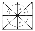
図5は、撮像素子と撮像レンズ10の移動方向の例を示したものであり、レンズ駆動機構40をX方向にのみ移動させると、撮像レンズ10の光軸は矢印Aで示すように、撮像素子の横辺に対して平行に移動する。また、レンズ駆動機構40をY方向にのみ移動させると、撮像レンズ10の光軸は矢印Bで示すように、撮像素子の縦辺に対して平行に移動する。さらに、レンズ駆動機構40をX方向及びY方向に移動させると、撮像レンズ10の光軸は矢印C又はDで示すように、撮像素子の対角線方向に平行移動する。あるいは、レンズ駆動機構40のX方向の移動量とY方向の移動量を適宜変化させることにより、これら以外の任意の方向に移動させることもできる。
【0042】
一般的に、例えば縦縞の服を着た人物や横縞の服を着た人物等のように、被写体によっては特定の方向において測距できない場合もあり得ることが知られている。従って、撮像レンズ10を2以上の方向に移動して測距できるようにしておけば、被写体の方向性による測距不能の可能性を小さくすることができる。また、測距精度を高くするには、測距装置の基線長を長くすればよいことが知られている。本実施形態の場合、図4に示す光軸L1とL2の距離DPを長くすればよい。すなわち、上記第1の位置P1及び第2の位置P2をそれぞれ各方向の移動可能限界又はその近傍に設定することにより、測距精度を可能な限り高くすることができる。
【0043】
図6は、撮像レンズ10により結像される画面中における測距エリアの配置を示す図であり、(a)は画面中央部のみに測距エリアを設定した場合、(b)は画面中央部及びその周辺に複数の測距エリアを設定した場合を示す。
【0044】
周知のように、人物が2人並んだ場合のように、画面中央部に主要被写体が存在しない場合もあり得る。その場合、図6(a)に示すように画面中央部のみに測距エリアが設定されている場合、撮像前に撮像装置1を振ってビューファインダ2に表示される測距エリアを主要被写体に合致させ、その状態で測距を行い、主要被写体に合焦させた状態で撮像レンズ10のフォーカス機構をロックし、撮像装置1を元の位置に戻して撮像を行う。一方、図6(b)に示すように複数の測距エリアが設定されている場合、撮像装置1をそのままにして各測距エリアについてそれぞれ測距を行い、得られた距離のうち撮像装置に最も近い値を被写体までの距離として用い、合焦動作を行う。
【0045】
なお、撮像部20の撮像素子としてはCCDやC−MOSセンサ等の2次元固体撮像素子を用いることができるが、CCDの場合特定部分の画素データのみを読み出すことはできず、1画面分の画素データを順次読み出して、その中から測距に使用される画素データを抽出する必要がある。そのため、第1画像情報を得てから第2画像情報を得るまでの間に被写体が大きく動くと、第1画像情報と第2画像情報を比較しても画素データが同じパターンで並んでいる箇所を見付けられない場合も起こりうる。これに対して、C−MOSセンサの場合、特定部分の画素データのみを読み出すことが可能であるので、演算処理速度を速くすることができ、動いている被写体に対して測距することも可能である。
【0046】
また、本実施形態の測距装置は、撮像レンズ10を透過した光束を用いて測距を行っており、いわゆるTTL(Through The Lens)タイプの測距装置であり、従来例で説明したような赤外線アクティブ方式のようにパララックスによる影響を受けない。そのため、接写や近接撮影等の場合のように、撮像装置1から至近距離にある被写体に対しても、正確に距離を測定することができる。
【0047】
ところで、撮像装置1からおおむね1m以上無限遠までに存在する被写体(通常撮影)に対しては、撮像レンズ10の焦点位置の初期設定として、例えば1m以上4m以下程度の範囲内にある任意の距離(例えば3m)に設定しておけば、多少ぼやけていても撮像素子により被写体像を撮像し、被写体までの距離を演算することが可能である。これに対して、撮像装置1から1m以内に存在する被写体(接写又は近接撮影)に対しては、撮像レンズ10の焦点位置を上記3mに初期設定すると、像のぼけが大きく、被写体像のコントラストが低すぎるので、被写体までの距離を演算することが不可能な場合も生ずる。そこで、撮像レンズ10の焦点位置を上記3mに初期設定して被写体までの距離が演算できなかった場合、被写体が至近距離にあると推定して、撮像レンズ10の焦点位置を20cm以上1m未満程度の範囲の任意の距離(例えば50cm)に設定し直し、改めて測距動作を行うようにしてもよい。
【0048】
あるいは、被写体が撮像装置1から1m以上無限遠までに存在する場合であっても、最初の演算により得られた被写体までの距離が初期設定距離から大きくずれている場合、撮像レンズ10の焦点位置を演算により得られた被写体までの距離に設定し直して、改めて測距動作を行うようにしてもよい。
【0049】
さらに、上記測距装置により得られた被写体までの距離を用いて被写体に合焦した後、撮像素子から出力される画像データを用いて公知のコントラスト方式により合焦確認(微調整)を行うようにしてもよい。
【0050】
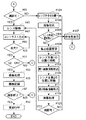
次に、本実施形態の撮像装置1による測距及び撮像動作について、図7〜図9に示すフローチャートを用いて説明する。
【0051】
ユーザが図示しないメインスイッチをオンすると、全体制御部50は図2に示す各部に電力供給を開始して動作可能状態に設定する(ステップ#1)。次に、全体制御部50は、ユーザによるモード選択スイッチの操作を監視し、撮影モードが選択されたことを確認する(ステップ#3)。次に、全体制御部50は、ユーザが表示部5をビューファインダとして選択しているか否かを判断する(ステップ#5)。
【0052】
ユーザが表示部5のビューファインダとしての使用を選択していない場合(ステップ#5でNO)、全体制御部50はフォーカス制御部14を制御して、撮像レンズ10の焦点位置を初期位置(例えば3m)に設定する(ステップ#7)。このとき、撮像レンズ10の焦点距離は基本的に任意であるが、測距精度を高くするためには、より長い方が好ましい。そのため、光学式ビューファインダ2の像倍率をユーザが設定した焦点距離に設定しておき、撮像レンズ10の焦点距離はその最長焦点距離に設定してもよい。
【0053】
次に、全体制御部50は、ユーザがシャッタレリーズスイッチ4に指をかけたり、あるいは途中まで押し下げたときにオンするスイッチS1がオンするのを待つ(ステップ#9)。スイッチS1がオンすると、ユーザが撮像態勢に入っているので、撮像部20及び信号処理部30を起動して、測距装置の構成要素として使用しうる状態に設定する(ステップ#11)。
【0054】
次に、全体制御部50はレンズ駆動機構40を駆動して、撮像レンズ10を第1の位置に移動させ(ステップ#13)、撮像部20により第1画像情報を取り込む(ステップ#15)。さらに、全体制御部50はレンズ駆動機構40を逆方向に駆動して、撮像レンズ10を基準位置に対して第1の位置とは対称な第2の位置に移動させ(ステップ#17)、撮像部20により第2画像情報を取り込む(ステップ#19)。第1画像情報及び第2画像情報が得られると、信号処理部30は、第1画像情報と第2画像情報を比較し、画素データが同じパターンで並んでいる箇所を見つけ、上記演算式に基づいて被写体までの距離を求める(ステップ#21)。
【0055】
一方、ユーザが表示部5のビューファインダとしての使用を選択している場合(ステップ#5でYES)、全体制御部50は、表示部5上にモニタ画像を表示するために、撮像部20及び信号処理部30を起動して、公知のコントラスト方式による合焦装置として使用しうる状態に設定する(ステップ#23)。表示部5上にモニタ画像が表示されると、全体制御部50は、ユーザによりスイッチS1がオンされるのを待つ(ステップ#27)。
【0056】
スイッチS1がオンされると、表示部5に表示されているモニタ画像を更新するまでの間に、全体制御部50は、レンズ駆動機構40を駆動して、撮像レンズ10を第1の位置に移動させ(ステップ#29)、撮像部20により第1画像情報を取り込み(ステップ#31)、レンズ駆動機構40を逆方向に駆動して、撮像レンズ10を第2の位置に移動させ(ステップ#33)、撮像部20により第2画像情報を取り込み(ステップ#35)、信号処理部30により被写体までの距離を求める(ステップ#37)。
【0057】
ステップ#21又は#37において信号処理部30により第1画像情報と第2画像情報を用いて被写体までの距離を演算すると、全体制御部50は演算結果に基づいて、被写体までの距離が測定できたか否かを判断する(ステップ#41)。被写体までの距離が測定できなかった場合、フォーカス制御部14を駆動して、撮像レンズ10の焦点位置を変更し(ステップ#43)、ステップ#13から#21の測距動作をやり直す。一方、被写体までの距離が演算できた場合(ステップ#41でYES)、全体制御部50は、レンズ駆動機構40を駆動して撮像レンズ10を基準位置に戻すと共に、フォーカス制御部14を制御して、信号処理部30により演算された距離を用いて被写体に合焦させるように撮像レンズ10を駆動する(ステップ#45)。なお、撮像レンズ10の焦点距離をその最長焦点距離に設定している場合は、同時にズーム制御部13を制御して、ユーザが設定している焦点距離に戻す。
【0058】
ところで、コントラスト方式による合焦確認を併用していない場合は、図8に示すように、全体制御部50は、ユーザによりシャッタレリーズスイッチ4が最後まで押し込まれたときにオンするスイッチS2がオンするのを待つ(ステップ#51)。一方、コントラスト方式による合焦確認を併用している場合は、図9に示すように、全体制御部50は、撮像部20及び信号処理部30を制御して、画像データを取り込み、画像データのコントラストが最大となるように、フォーカス制御部14を制御して撮像レンズ10の焦点位置を微調整しながら(ステップ#47,#49)、スイッチS2がオンするのを待つ(ステップ#51)。
【0059】
スイッチS2がオンすると(ステップ#51でYES)、全体制御部50は、撮像部20、信号処理部30及び図示しない露光制御機構(例えばNDフィルタの挿入/取り外し、絞り制御、メカニカルシャッタ制御、撮像素子の電荷蓄積時間制御等)を制御して、適正な露光量で撮像素子を露光し、撮像素子から出力された画像データのホワイトバランス調節、γ補正、JPEG圧縮等の所定の信号処理を施し、(ステップ#53)、記録部17により記録媒体に画像データを記録する(ステップ#55)。
【0060】
画像データを記録し終えると、全体制御部50はユーザによりメインスイッチがオフされたか否か、すなわち撮像モードを終了してもよいか否かを判断する(ステップ#57)。一定時間メインスイッチがオフされない場合(ステップ#57でNO)、ステップ#7又は#25に戻って次の撮像に備える。また、ステップ#51において、一定時間スイッチS2がオンされなかった場合も、ステップ#7又は#25に戻って次の撮像に備える。一方、メインスイッチがオフされると(ステップ#57でYES)、全体制御部50は各部への電力供給を停止し(ステップ#59)、撮像モードを終了する。
【0061】
次に、本実施形態の撮像装置1による測距及び撮像動作の変形例について、図10及び図11に示すフローチャートを用いて説明する。なお、図10は図7とほぼ同じ(ステップ#13に戻るルートがない点のみ異なる)であるため、その説明を省略する。
【0062】
図11のステップ#41において被写体までの距離が測定できなかった場合、この変形例では、全体制御部50は、レンズ駆動機構40を駆動して、撮像レンズ10を基準位置に一旦復帰させる(ステップ#101)。そして、撮像部20により画像データを取り込む(ステップ#103)。この画像データは、信号処理部30により所定の処理を受けた後記憶部18に記憶され、後にコントラスト方式の合焦動作を行う際、新たに取り込まれる画像と比較される。
【0063】
次に、全体制御部50は、フォーカス制御部14から出力される信号を参照して、撮像レンズ10の焦点位置が撮像装置1に最も近い位置(最近端)にあるか否かを判断する(ステップ#105)。撮像レンズ10の焦点位置が最近端の場合(ステップ#105でYES)、それ以上撮像レンズ10の焦点位置を動かすことができず合焦不可能であるので、全体制御部50は表示部5を制御して、所定の非合焦表示を行う(ステップ#107)。
【0064】
撮像レンズ10の焦点位置が最近端でない場合(ステップ#105でNO)、全体制御部50は、フォーカス制御部14を制御して、撮像レンズ10の焦点位置を変更し(ステップ#109)、さらにレンズ駆動機構40を駆動して、撮像レンズ10を第1の位置に移動させ(ステップ#111)、撮像部20により第1画像情報を取り込む(ステップ#113)。さらに、全体制御部50はレンズ駆動機構40を逆方向に駆動して、撮像レンズ10を基準位置に対して第1の位置とは対称な第2の位置に移動させ(ステップ#115)、撮像部20により第2画像情報を取り込む(ステップ#117)。第1画像情報及び第2画像情報が得られると、信号処理部30は、第1画像情報と第2画像情報を比較して被写体までの距離を求めると共に、ステップ#103で取り込んだ画像データと新たに取り込んだ画像データ(第1画像情報及び/又は第2画像情報)とを比較して、コントラスト方式による合焦確認も行う(ステップ#119)。
【0065】
次に、全体制御部50はステップ#119における演算結果に基づいて、被写体までの距離が測定できたか否かを判断する(ステップ#121)。被写体までの距離が測定できなかった場合、ステップ#101〜#119までのいわゆるローコンスキャン動作をやり直す。一方、被写体までの距離が演算できた場合(ステップ#121でYES)、全体制御部50は、ステップ#45〜#59のフローを実行する。
【0066】
このように、上記変形例では、例えば被写体が撮像装置1から近い位置にあり、最初の測距動作では被写体像のぼけが大きく、コントラストが低すぎて本実施形態の測距装置による三角測距方式では距離を測定できない場合に、コントラスト方式による合焦動作を併用するので、可能な限り被写体に合焦させることができる。
【0067】
さらに、撮像レンズ10の焦点距離又は像倍率に応じて、測距装置による被写体までの距離測定と撮像素子により得られた前記画像データのコントラストが最大となるように撮像レンズ10の焦点位置を移動させる方式のいずれかを選択することにより、高解像度が必要な場合にはより合焦精度の高い方法を選択し、解像度がそれほど必要とされない場合にはより合焦速度の速い方法を選択するように構成してもよい。
【0068】
また、上記実施形態の説明では、手振れ補正については特に言及しなかったが、上記レンズ駆動機構40を測距装置として使用し、被写体までの距離を測定した後、記録媒体に記録するための画像データを撮像する際には、レンズ駆動機構40を手振れ補正機構として用い、撮像レンズ10を手振れ方向とは逆の方向に、手振れ量に相当する量だけ移動させることはいうまでもない。
【0069】
さらに、上記実施形態では、表示部5と記録部17の両方を備えた場合について説明したが、本発明はこれに限定されるものではなく、表示部5と記録部17のいずれか一方が備えられていればよい。表示部5を含まない撮像装置としては、例えば光学式ビューファインダのみを備えたディジタルカメラ等が考えられる。また、記録部17を含まない撮像装置としては、例えば、観光用にタワー頂上に設置されたリモコン操作可能なカメラ(映像は大型スクリーンに映し出され、望遠鏡の代わりとなる)等が考えられる。また、ビデオカメラの初期のフォーカス調整にも使用可能である。
【0070】
【発明の効果】
以上説明したように、本発明の測距装置によれば、被写体像を所定位置に結像させるための撮像レンズと、前記被写体像の結像面に設けられ、光電変換により前記被写体像を所定の電気信号に変換する撮像素子と、前記撮像レンズをその光軸に直交する面内で平行移動させるレンズ駆動機構と、前記撮像素子及び前記レンズ駆動機構を制御する制御部とを具備し、前記制御部は、前記レンズ駆動機構を駆動して前記撮像レンズを前記光軸に直交する面内における任意の第1の位置に移動させ、前記撮像素子により被写体像を撮像し、第1画像情報として出力させ、次に前記レンズ駆動機構を制御して前記撮像レンズを前記撮像素子の中心に対して前記第1の位置と対称な第2の位置に移動させ、前記撮像素子により被写体像を撮像し、第2画像情報として出力させ、前記第1画像情報及び前記第2画像情報と、前記第1の位置と前記第2の位置の間の距離情報とを用いて被写体までの距離を演算し、出力する。
【0071】
すなわち、第1画像情報と第2画像情報を比較し、撮像素子の各画素に対応する画素データが同じパターンで並んでいる箇所が見つかると、それらが同一被写体の同一部分の像であると推定することができる。撮像素子上におけるこれら2つの部分の距離をDI、第1の位置と第2の位置の距離をDP、撮像レンズの焦点距離をfとして、被写体までの距離DOは、DO=f・DI/DPで表され、被写体までの距離が演算で求められる。
【0072】
また、駆動機構として、撮像レンズをその光軸に対して平行移動させる手振れ補正機構を用いることができ、短時間のうちに高速で撮像レンズを移動させ、第1画像情報及び第2画像情報を得ることができ、従来からディジタルカメラ等で行われているコントラスト方式よりも高速で、被写体の測距又は撮像レンズの合焦を行うことが可能となる。
【0073】
また、前記第1の位置及び前記第2の位置を、前記撮像素子の中心を通り前記撮像素子の縦辺に平行な線上、横辺に平行な線上及び対角線上のいずれかの位置とすることにより、撮像レンズ又は撮像素子を平行移動させるための互いに直交する方向に配置された2つのアクチュエータ(Xアクチュエータ及びYアクチュエータ)のうち、いずれか一方又は両方を同時に駆動すればよく、レンズ駆動機構の制御が比較的容易になる。また、被写体によっては水平方向又は垂直方向では測距できない場合もあり、測距方向を選択可能とすることにより、測距不能の場合をより少なくすることができる。
【0074】
さらに、前記第1の位置及び前記第2の位置を、前記各線上における移動可能限界位置とすることにより、各方向における第1の位置と第2の位置を最も長くすることができ、三角測距における基線長を長くすることができ、測距精度を高くすることが可能となる。
【0075】
さらに、前記撮像レンズの焦点位置を調節する焦点調節機構を具備し、前記第1画像情報及び前記第2画像情報からでは被写体までの距離が適切に得られなかった場合、前記制御部は、前記焦点調節機構を制御して、撮像レンズの焦点位置を変更し、測距動作をやり直すことにより、測距不能の可能性を少なくすることができる。
【0076】
さらに、前記撮像素子を、前記各位置にそれぞれ対応する1又は2以上の測距領域に含まれる画素からの電気信号のみを出力するように構成することにより、必要な信号のみを読み出すので(画素データの部分読み出し)、電気信号の読み出し時間及び画像情報の比較に要する時間を短縮することが可能となる。
【0077】
さらに、前記撮像素子をC−MOSセンサとすることにより、比較的簡単な処理で画素データの部分読み出しを実現することができる。
【0078】
さらに上記各構成において、前記撮像レンズの焦点位置を調節する焦点調節機構を具備し、前記制御部は、前記焦点調節機構を制御して前記撮像レンズの焦点位置を通常撮影に適する第1の距離範囲における任意の第1焦点位置に設定し、被写体までの距離を測定することにより、第1距離範囲に被写体が存在する可能性が高くなり、最初の測距動作で被写体までの距離を測定しうる確率が高くなる。
【0079】
さらに、前記撮像レンズの焦点位置を前記第1焦点位置に設定して被写体までの距離が適切に得られなかった場合、前記制御部は、前記焦点調節機構を制御して前記撮像レンズの焦点位置を接写又は近接撮影に適する第2の距離範囲における任意の第2焦点位置に設定し、再度被写体までの距離を測定することにより、接写や近接撮影等の場合であっても、パララックスによる影響を受けることなく正確に被写体までの距離を測定することが可能となる。
【0080】
さらに、前記第1の距離範囲を1m以上4m以下とし、第2の距離範囲を20cm以上1m未満とすることにより、被写体の位置が至近距離にある場合からほぼ無限遠にある場合までをカバーすることができる。
【0081】
一方、本発明の撮像装置によれば、上記いずれかの構成を有する測距装置と、前記撮像素子から出力される電気信号に所定の処理を施して画像データとして出力する信号処理部と、前記画像データを用いてモニタ画像を表示する表示部及び前記画像データを記録する記録部の少なくとも一方を具備するので、従来のコントラスト方式による合焦機能を有する撮像装置よりも高速で被写体の合焦動作を行うことができる。
【0082】
また、前記測距装置によっては被写体までの距離が適正に得られなかった場合に、前記制御部は、前記レンズ駆動機構を制御して前記撮像レンズを基準位置に固定し、前記撮像素子を所定間隔で駆動して電気信号を出力させ、前記信号処理部により処理された各画像データのコントラストを比較し、前記焦点調節機構を制御して前記画像データのコントラストが最大となるように前記撮像レンズの焦点位置を移動させることにより、本発明の測距装置による合焦方法と従来のコントラスト方式による合焦方法とを併用することができ、いずれかの方法を用いて合焦不能となる可能性を低くすることができる。
【0083】
または、前記制御部は、前記測距装置により得られた被写体までの距離を用いて前記焦点調節機構を制御して前記撮像レンズの焦点位置を移動させ、その後、前記レンズ駆動機構を駆動して前記撮像レンズを基準位置に固定し、前記撮像素子を所定間隔で駆動して電気信号を出力させ、前記信号処理部により処理された各画像データのコントラストを比較し、前記焦点調節機構を制御して前記画像データのコントラストが最大となるように前記撮像レンズの焦点位置を微調整することにより、2つの合焦方法を併用して合焦精度をより高くすることができる。
【0084】
さらに、撮像レンズの焦点距離又は像倍率に応じて、前記測距装置による被写体までの距離測定と前記撮像素子により得られた前記画像データのコントラストが最大となるように前記撮像レンズの焦点位置を移動させる方式のいずれかを選択することにより、高解像度が必要な場合にはより合焦精度の高い方法を選択し、解像度がそれほど必要とされない場合にはより合焦速度の速い方法を選択することが可能となる。
【0085】
さらに、上記各構成において、さらに手振れ検出センサを具備し、前記撮像レンズの焦点位置を調節した後、前記撮像素子により被写体像を撮像する間、前記駆動機構を駆動して前記撮像レンズを手振れ方向とは逆方向に、手振れ量に相当する量だけ移動させ、手振れ補正を行うことにより、本発明の測距装置を撮像時には手振れ補正機構として使用することができる。換言すれば、既に実用化されつつある手振れ補正機構を有する撮像装置に若干の改良を加えるだけで、本発明の測距装置及びそれを用いた撮像装置を実現することができる。
【図面の簡単な説明】
【図1】本発明の一実施形態における測距装置を用いた撮像装置の外観構成を示す斜視図である。
【図2】上記一実施形態における測距装置及びそれを用いた撮像装置のブロック構成を示す図である。
【図3】上記一実施形態におけるレンズ駆動機構の構成を示す分解斜視図である。
【図4】本発明に係る測距装置の測距原理を示す図である。
【図5】上記一実施形態におけるレンズ駆動機構による撮像レンズの移動方向の例を示す図である。
【図6】上記一実施形態における測距装置の測距ゾーンの配置例を示す図である。
【図7】上記一実施形態における測距動作を示すフローチャートである。
【図8】図7のフローチャートの続きである。
【図9】図8のフローチャートの続きの変形例である。
【図10】上記一実施形態における測距動作の変形例を示すフローチャートである。
【図11】図10のフローチャートの続きである。
【符号の説明】
1:撮像装置
2:光学式ビューファインダ
3:フラッシュ発光部
4:シャッタレリーズスイッチ
5:表示部
6:ズームスイッチ
10:撮像レンズ
11:ズーム用変倍レンズ群
12:フォーカス用合焦レンズ群
13:ズーム制御部
14:フォーカス制御部
15:ファインダ光学系
16:操作部
17:記録部
18:記憶部
20:撮像部
30:信号処理部
40:レンズ駆動機構
50:全体制御部[0001]
TECHNICAL FIELD OF THE INVENTION
The present invention relates to a distance measuring device for an imaging device such as a digital camera using a solid-state imaging device.
[0002]
[Prior art]
2. Description of the Related Art An imaging apparatus such as a digital camera using a solid-state imaging device is generally provided with an autofocus mechanism for automatically adjusting the focus of an imaging lens. In particular, since information (for example, contrast information) regarding a subject image is directly output as an electric signal from the solid-state imaging device, the focal position of the imaging lens is gradually changed while monitoring the output signal from the imaging device, so that the contrast is maximized. The imaging lens may be stopped at a certain position. This method is called a "contrast method" or a "hill-climbing method", and uses an image sensor as a distance measuring sensor and does not require a special distance measuring mechanism, and is therefore widely used in digital cameras and the like.
[0003]
[Problems to be solved by the invention]
However, according to the above-described contrast method, the amount of movement (defocus amount) of the imaging lens cannot be calculated in one imaging operation, and it is necessary to repeatedly perform imaging while moving the focal position of the imaging lens by a small amount. Instead, it takes a certain time to focus the subject image on the image sensor. Therefore, there is a problem that the response speed by the contrast method is slower than the response speed of an autofocus mechanism such as a camera using a silver halide film which requires a dedicated distance measuring mechanism.
[0004]
Digital cameras that use both the contrast method and the infrared active method are commercially available to compensate for the drawbacks of the above-mentioned contrast method. However, since the infrared active method is not TTL, parallax occurs in close-range imaging such as close-up photography. However, there is a problem that it can only be used.
[0005]
On the other hand, a camera shake correction mechanism that detects a camera shake direction and a camera shake amount during imaging and moves the imaging lens by an amount corresponding to the camera shake amount in a direction opposite to the camera shake direction has been put to practical use. This camera shake correction mechanism is a high-performance mechanism that can move the imaging lens at high speed in a very short time during imaging, but only under conditions that easily cause camera shake, for example, under conditions where the brightness of the subject is low and the exposure time is long. It is not needed when the flash is used together or when the brightness of the subject is high, and there is a problem that the precious function is not effectively used.
[0006]
The present invention has been made in order to solve the problems of the above conventional example, and provides a distance measuring apparatus that measures the distance to a subject using a camera shake correction mechanism and an imaging apparatus using the same. The purpose is.
[0007]
[Means for Solving the Problems]
In order to achieve the above object, a distance measuring apparatus according to the present invention is provided with an imaging lens for forming a subject image at a predetermined position and a focusing surface of the subject image. An imaging device that converts the image into an electric signal, a lens driving mechanism that translates the imaging lens in a plane perpendicular to the optical axis thereof, and a control unit that controls the imaging device and the lens driving mechanism. The unit drives the lens driving mechanism to move the imaging lens to an arbitrary first position in a plane orthogonal to the optical axis, captures a subject image by the imaging element, and outputs the captured image as first image information. Controlling the lens driving mechanism to move the imaging lens to a second position symmetrical to the first position with respect to the center of the imaging device, and captures a subject image by the imaging device; 2nd image And calculating a distance to a subject using the first image information and the second image information and distance information between the first position and the second position, and outputting the calculated information. Features.
[0008]
In the above configuration, the first position and the second position are any positions on a line passing through the center of the image sensor and parallel to a vertical side of the image sensor, a line parallel to a horizontal side, and a diagonal line. Preferably, there is.
[0009]
Further, it is preferable that the first position and the second position are movable limit positions on the respective lines.
[0010]
further, A focus adjustment mechanism for adjusting a focus position of the imaging lens, If the distance to the subject is not properly obtained from the first image information and the second image information, the control unit may Control the focus adjustment mechanism to change the focal position of the imaging lens and redo the distance measurement operation Is preferred.
[0011]
Furthermore, it is preferable that the imaging element outputs only an electric signal from a pixel included in one or more distance measurement areas corresponding to each of the positions.
[0012]
Further, it is preferable that the imaging device is a C-MOS sensor.
[0013]
Further, a focus adjustment mechanism for adjusting a focus position of the imaging lens is provided, and the control unit controls the focus adjustment mechanism to set a focus position of the imaging lens in a first distance range suitable for normal photographing. It is preferable to set the first focus position and measure the distance to the subject.
[0014]
Further, when the focus position of the imaging lens is set to the first focus position and the distance to the subject is not properly obtained, the control unit controls the focus adjustment mechanism to control the focus position of the imaging lens. Is preferably set to an arbitrary second focal position in a second distance range suitable for close-up photography or close-up photography, and the distance to the subject is measured again.
[0015]
Further, it is preferable that the first distance range is 1 m or more and 4 m or less, and the second distance range is 20 cm or more and less than 1 m.
[0016]
On the other hand, an imaging device of the present invention includes a distance measuring device having any one of the above configurations, a signal processing unit that performs predetermined processing on an electric signal output from the imaging element and outputs the processed signal as image data, And at least one of a display unit that displays a monitor image by using a computer and a recording unit that records the image data.
[0017]
In the above configuration, when the distance to the subject is not properly obtained by the distance measuring device, the control unit controls the lens driving mechanism to fix the imaging lens at a reference position, and the imaging device Is driven at predetermined intervals to output an electric signal, compare the contrast of each image data processed by the signal processing unit, and control the focus adjustment mechanism so that the contrast of the image data is maximized. It is preferable to move the focal position of the imaging lens.
[0018]
Alternatively, the control unit controls the focus adjustment mechanism using the distance to the subject obtained by the distance measuring device to move the focal position of the imaging lens, and then drives the lens driving mechanism. The imaging lens is fixed at a reference position, the imaging element is driven at predetermined intervals to output an electric signal, the contrast of each image data processed by the signal processing unit is compared, and the focus adjustment mechanism is controlled. Preferably, the focus position of the imaging lens is finely adjusted so that the contrast of the image data is maximized.
[0019]
Further, according to the focal length or the image magnification of the imaging lens, the distance measurement to the subject by the distance measuring device and the focal position of the imaging lens are set so that the contrast of the image data obtained by the imaging device is maximized. It is preferable to select one of the moving methods.
[0020]
Furthermore, in each of the above-described configurations, the camera further includes a camera shake detection sensor, and after adjusting a focal position of the imaging lens, drives the lens driving mechanism to move the imaging lens in a camera shake direction while capturing a subject image by the imaging element. It is preferable to perform the camera shake correction by moving the camera in the opposite direction by an amount corresponding to the camera shake amount.
[0021]
BEST MODE FOR CARRYING OUT THE INVENTION
An embodiment of the present invention will be described. FIG. 1 is a diagram illustrating an appearance of a digital camera having a camera shake correction function, which is an imaging device according to the present embodiment. On the front surface of the
[0022]
FIG. 2 shows a block configuration of the
[0023]
The variable
[0024]
An independent zoom drive mechanism and a focus drive mechanism (both not shown) are engaged with the outer cylinders of the variable
[0025]
When the automatic focusing mode (AF mode) is selected, the
[0026]
On the other hand, the
[0027]
Further, the
[0028]
The
[0029]
The
[0030]
The
[0031]
The
[0032]
The
[0033]
As the
[0034]
Next, the configuration of the
[0035]
[0036]
The
[0037]
Next, the principle of distance measurement of the distance measuring apparatus according to the present embodiment will be described with reference to FIG. In FIG. 4, O is a subject, P 0 Is the reference position of the
[0038]
First, the
[0039]
The first image information and the second image information are compared, and when a portion where pixel data corresponding to each pixel of the image sensor is arranged in the same pattern is found, it is estimated that these are images of the same portion of the same subject O. be able to. Distance D between these two parts on the image sensor I , The distance D between the first position and the second position P From the focal length f of the imaging lens to the distance D to the subject O Is D O = FD I / D P And the distance D to the subject O O Is obtained by calculation.
[0040]
The direction in which the
[0041]
FIG. 5 shows an example of the moving direction of the imaging element and the
[0042]
In general, it is known that there may be cases where distance measurement cannot be performed in a specific direction depending on a subject, such as a person wearing vertical striped clothes or a person wearing horizontal striped clothes. Therefore, if the
[0043]
FIGS. 6A and 6B are diagrams showing the arrangement of distance measurement areas in a screen imaged by the
[0044]
As is well known, there may be cases where the main subject does not exist at the center of the screen, such as when two people are lined up. In this case, if the distance measurement area is set only at the center of the screen as shown in FIG. 6A, the
[0045]
Note that a two-dimensional solid-state imaging device such as a CCD or a C-MOS sensor can be used as an imaging device of the
[0046]
Further, the distance measuring apparatus of the present embodiment measures the distance using the light beam transmitted through the
[0047]
By the way, with respect to a subject (normal photographing) existing approximately 1 m or more to infinity from the
[0048]
Alternatively, even when the object is present at a distance of 1 m or more from the
[0049]
Further, after focusing on the subject using the distance to the subject obtained by the distance measuring device, focus confirmation (fine adjustment) is performed by a known contrast method using image data output from the image sensor. It may be.
[0050]
Next, distance measurement and imaging operations performed by the
[0051]
When the user turns on a main switch (not shown), the
[0052]
If the user has not selected the use of the
[0053]
Next, the
[0054]
Next, the
[0055]
On the other hand, when the user has selected to use the
[0056]
When the switch S1 is turned on, the
[0057]
In
[0058]
By the way, when the focus confirmation by the contrast method is not used at the same time, as shown in FIG. 8, the
[0059]
When the switch S2 is turned on (YES in step # 51), the
[0060]
When the recording of the image data is completed, the
[0061]
Next, a modified example of the distance measurement and the imaging operation by the
[0062]
If the distance to the subject cannot be measured in
[0063]
Next, the
[0064]
If the focal position of the
[0065]
Next, the
[0066]
As described above, in the above-described modification, for example, the subject is located close to the
[0067]
Further, the focal position of the
[0068]
Also, in the description of the above embodiment, the camera shake correction is not particularly mentioned, but the image to be recorded on the recording medium after measuring the distance to the subject by using the
[0069]
Further, in the above-described embodiment, the case where both the
[0070]
【The invention's effect】
As described above, according to the distance measuring apparatus of the present invention, an imaging lens for forming an image of a subject at a predetermined position, and the imaging lens provided on the image forming surface of the subject image, and the subject image is formed by photoelectric conversion. An image sensor that converts the image signal into an electric signal, a lens driving mechanism that translates the imaging lens in a plane perpendicular to the optical axis thereof, and a control unit that controls the image sensor and the lens driving mechanism. The control unit drives the lens driving mechanism to move the imaging lens to an arbitrary first position in a plane orthogonal to the optical axis, captures a subject image using the imaging element, and outputs the captured image as first image information. Output, and then moving the imaging lens to a second position symmetrical to the first position with respect to the center of the imaging device by controlling the lens driving mechanism, and capturing an object image by the imaging device. , 2nd stroke Is output as information, with the first image information and the second image information, by using the distance information between the first position and the second position to calculate the distance to the subject, and outputs.
[0071]
That is, the first image information and the second image information are compared, and if a portion where pixel data corresponding to each pixel of the image sensor is arranged in the same pattern is found, it is estimated that these are images of the same portion of the same subject. can do. The distance between these two parts on the image sensor is D I , The distance between the first position and the second position is D P , The focal length of the imaging lens as f, the distance D to the subject O Is D O = FD I / D P The distance to the subject is obtained by calculation.
[0072]
In addition, as a driving mechanism, a camera shake correction mechanism that moves the imaging lens in parallel with its optical axis can be used, and the imaging lens is moved at high speed in a short time, and the first image information and the second image information are transferred. This makes it possible to perform distance measurement of an object or focus an imaging lens at a higher speed than a contrast method conventionally used in a digital camera or the like.
[0073]
Further, the first position and the second position may be any positions on a line passing through the center of the image sensor and parallel to a vertical side, a line parallel to a horizontal side, and a diagonal line of the image sensor. Therefore, one or both of two actuators (X actuator and Y actuator) arranged in directions orthogonal to each other for moving the imaging lens or the imaging device in parallel can be driven at the same time. Control becomes relatively easy. Also, depending on the subject, distance measurement may not be possible in the horizontal direction or the vertical direction. By making the distance measurement direction selectable, the number of cases where distance measurement is impossible can be reduced.
[0074]
Further, by setting the first position and the second position as movable limit positions on the respective lines, the first position and the second position in each direction can be made the longest, and triangulation can be performed. The base line length in the distance can be lengthened, and the distance measurement accuracy can be increased.
[0075]
further, A focus adjustment mechanism for adjusting a focus position of the imaging lens, When the distance to the subject is not properly obtained from the first image information and the second image information, The focus adjustment mechanism is controlled to change the focal position of the imaging lens, and the distance measurement operation is performed again. This can reduce the possibility that the distance measurement cannot be performed.
[0076]
Further, since the image sensor is configured to output only electric signals from pixels included in one or more distance measurement areas corresponding to the respective positions, only necessary signals are read out. It is possible to shorten the time required for reading data (partial reading), the time required to read electric signals, and the time required to compare image information.
[0077]
Furthermore, by using a C-MOS sensor as the image sensor, partial reading of pixel data can be realized by relatively simple processing.
[0078]
Further, in each of the above-described configurations, a focus adjustment mechanism that adjusts a focal position of the imaging lens is provided, and the control unit controls the focus adjustment mechanism to set a focal position of the imaging lens to a first distance suitable for normal photographing. By setting an arbitrary first focal position in the range and measuring the distance to the subject, the possibility that the subject is present in the first distance range increases, and the distance to the subject is measured in the first distance measurement operation. Probability increases.
[0079]
Further, when the focus position of the imaging lens is set to the first focus position and the distance to the subject is not properly obtained, the control unit controls the focus adjustment mechanism to control the focus position of the imaging lens. Is set to an arbitrary second focal position within a second distance range suitable for close-up photography or close-up photography, and the distance to the subject is measured again. It is possible to accurately measure the distance to the subject without receiving the light.
[0080]
Further, by setting the first distance range to be 1 m or more and 4 m or less and the second distance range to be 20 cm or more and less than 1 m, the case where the position of the subject is at a close distance to a case where it is at almost infinity is covered. be able to.
[0081]
On the other hand, according to the imaging device of the present invention, a distance measuring device having any one of the above configurations, a signal processing unit that performs predetermined processing on an electrical signal output from the imaging element and outputs the processed signal as image data, Since at least one of a display unit that displays a monitor image using image data and a recording unit that records the image data is provided, the focusing operation of the subject can be performed at a higher speed than an imaging apparatus having a focusing function using a conventional contrast method. It can be performed.
[0082]
When the distance to the subject is not properly obtained by the distance measuring device, the control unit controls the lens driving mechanism to fix the imaging lens at a reference position, and moves the imaging element to a predetermined position. The imaging lens is driven at intervals to output an electric signal, the contrast of each image data processed by the signal processing unit is compared, and the focus adjustment mechanism is controlled so that the contrast of the image data is maximized. By moving the focal position of the present invention, it is possible to use both the focusing method by the distance measuring apparatus of the present invention and the focusing method by the conventional contrast method, and there is a possibility that focusing cannot be performed using either method. Can be lowered.
[0083]
Alternatively, the control unit controls the focus adjustment mechanism using the distance to the subject obtained by the distance measuring device to move the focal position of the imaging lens, and then drives the lens driving mechanism. The imaging lens is fixed at a reference position, the imaging element is driven at predetermined intervals to output an electric signal, the contrast of each image data processed by the signal processing unit is compared, and the focus adjustment mechanism is controlled. By finely adjusting the focal position of the imaging lens so that the contrast of the image data is maximized, the focusing accuracy can be further improved by using two focusing methods in combination.
[0084]
Further, according to the focal length or the image magnification of the imaging lens, the distance measurement to the subject by the distance measuring device and the focal position of the imaging lens are set so that the contrast of the image data obtained by the imaging device is maximized. By selecting one of the moving methods, a method with a higher focusing accuracy is selected when high resolution is required, and a method with a faster focusing speed is selected when high resolution is not required. It becomes possible.
[0085]
Further, in each of the above-described configurations, the camera further includes a camera shake detection sensor, and after adjusting a focal position of the imaging lens, drives the driving mechanism to move the imaging lens in a camera shake direction while capturing an object image by the imaging device. By moving the camera in the opposite direction by an amount corresponding to the camera shake amount and performing camera shake correction, the distance measuring apparatus of the present invention can be used as a camera shake correction mechanism during imaging. In other words, the ranging device of the present invention and an imaging device using the same can be realized by only slightly improving an imaging device having a camera shake correction mechanism that is already being put into practical use.
[Brief description of the drawings]
FIG. 1 is a perspective view illustrating an external configuration of an imaging device using a distance measuring device according to an embodiment of the present invention.
FIG. 2 is a diagram showing a block configuration of a distance measuring apparatus and an imaging apparatus using the same in the embodiment.
FIG. 3 is an exploded perspective view illustrating a configuration of a lens driving mechanism in the embodiment.
FIG. 4 is a diagram illustrating the principle of distance measurement of the distance measurement device according to the present invention.
FIG. 5 is a diagram illustrating an example of a moving direction of an imaging lens by a lens driving mechanism according to the embodiment.
FIG. 6 is a diagram showing an example of the arrangement of distance measuring zones of the distance measuring device in the embodiment.
FIG. 7 is a flowchart showing a distance measuring operation in the embodiment.
FIG. 8 is a continuation of the flowchart of FIG. 7;
FIG. 9 is a modified example of a continuation of the flowchart in FIG. 8;
FIG. 10 is a flowchart showing a modified example of the distance measuring operation in the embodiment.
FIG. 11 is a continuation of the flowchart in FIG. 10;
[Explanation of symbols]
1: Imaging device
2: Optical viewfinder
3: Flash emitting part
4: Shutter release switch
5: Display section
6: Zoom switch
10: Imaging lens
11: Zoom lens group for zoom
12: Focusing lens group for focus
13: Zoom control unit
14: Focus control unit
15: Viewfinder optical system
16: Operation unit
17: Recorder
18: Storage unit
20: imaging unit
30: signal processing unit
40: Lens drive mechanism
50: Overall control unit
Claims (14)
前記制御部は、前記レンズ駆動機構を駆動して前記撮像レンズを前記光軸に直交する面内における任意の第1の位置に移動させ、前記撮像素子により被写体像を撮像し、第1画像情報として出力させ、
次に前記レンズ駆動機構を制御して前記撮像レンズを前記撮像素子の中心に対して前記第1の位置と対称な第2の位置に移動させ、前記撮像素子により被写体像を撮像し、第2画像情報として出力させ、
前記第1画像情報及び前記第2画像情報と、前記第1の位置と前記第2の位置の間の距離情報とを用いて被写体までの距離を演算し、出力することを特徴とする測距装置。An imaging lens for forming a subject image at a predetermined position; an imaging device provided on an imaging surface of the subject image, for converting the subject image into a predetermined electric signal by photoelectric conversion; A lens driving mechanism for performing parallel movement in a plane perpendicular to the axis, and a control unit for controlling the image sensor and the lens driving mechanism,
The control unit drives the lens driving mechanism to move the imaging lens to an arbitrary first position in a plane orthogonal to the optical axis, captures a subject image by the imaging element, and stores first image information Output as
Next, the lens driving mechanism is controlled to move the imaging lens to a second position symmetrical to the first position with respect to the center of the imaging device, and a subject image is taken by the imaging device. Output as image information,
Calculating a distance to a subject using the first image information and the second image information and distance information between the first position and the second position, and outputting the distance; apparatus.
Priority Applications (1)
| Application Number | Priority Date | Filing Date | Title |
|---|---|---|---|
| JP2001098948A JP3551932B2 (en) | 2001-03-30 | 2001-03-30 | Distance measuring device and imaging device using the same |
Applications Claiming Priority (1)
| Application Number | Priority Date | Filing Date | Title |
|---|---|---|---|
| JP2001098948A JP3551932B2 (en) | 2001-03-30 | 2001-03-30 | Distance measuring device and imaging device using the same |
Publications (2)
| Publication Number | Publication Date |
|---|---|
| JP2002296491A JP2002296491A (en) | 2002-10-09 |
| JP3551932B2 true JP3551932B2 (en) | 2004-08-11 |
Family
ID=18952550
Family Applications (1)
| Application Number | Title | Priority Date | Filing Date |
|---|---|---|---|
| JP2001098948A Expired - Fee Related JP3551932B2 (en) | 2001-03-30 | 2001-03-30 | Distance measuring device and imaging device using the same |
Country Status (1)
| Country | Link |
|---|---|
| JP (1) | JP3551932B2 (en) |
Families Citing this family (9)
| Publication number | Priority date | Publication date | Assignee | Title |
|---|---|---|---|---|
| KR100547998B1 (en) * | 2003-02-10 | 2006-02-01 | 삼성테크윈 주식회사 | Control method of digital camera informing that photographing state was inadequate |
| JP2006046935A (en) | 2004-07-30 | 2006-02-16 | Matsushita Electric Ind Co Ltd | Distance measuring optical device, distance measuring method, distance measuring system, on-vehicle imaging device and on-vehicle operation-support device |
| JP2006171286A (en) * | 2004-12-15 | 2006-06-29 | Pentax Corp | Driving mechanism for camera |
| JP2007121504A (en) * | 2005-10-26 | 2007-05-17 | Canon Inc | Focus detection apparatus and method, and imaging apparatus |
| JP5110799B2 (en) * | 2006-03-07 | 2012-12-26 | ペンタックスリコーイメージング株式会社 | Camera with anti-vibration function |
| JP4844177B2 (en) | 2006-03-07 | 2011-12-28 | 株式会社ニコン | Blur correction device and camera |
| JP5023750B2 (en) * | 2007-03-16 | 2012-09-12 | 株式会社ニコン | Ranging device and imaging device |
| KR101406802B1 (en) * | 2007-10-16 | 2014-06-12 | 삼성전자주식회사 | Apparatus and method for digital picturing image |
| CN213585933U (en) * | 2020-10-15 | 2021-06-29 | 深圳市大疆创新科技有限公司 | Shooting auxiliary structure and shooting equipment |
-
2001
- 2001-03-30 JP JP2001098948A patent/JP3551932B2/en not_active Expired - Fee Related
Also Published As
| Publication number | Publication date |
|---|---|
| JP2002296491A (en) | 2002-10-09 |
Similar Documents
| Publication | Publication Date | Title |
|---|---|---|
| JP5284954B2 (en) | Method and system for image stabilization | |
| JP5564996B2 (en) | Imaging apparatus and imaging method | |
| US20150092098A1 (en) | Image capturing apparatus and control method thereof | |
| EP2212731B1 (en) | Image sensing apparatus | |
| JP4533735B2 (en) | Stereo imaging device | |
| JP4731705B2 (en) | Imaging apparatus, camera, photographing lens, focus adjustment method, and storage medium | |
| JP2005301269A (en) | Photographing apparatus having burst zoom mode | |
| JP2008199477A (en) | Imaging apparatus | |
| JP4607822B2 (en) | Digital camera | |
| JP2006162991A (en) | Stereoscopic image photographing apparatus | |
| JP3551932B2 (en) | Distance measuring device and imaging device using the same | |
| JP2011091636A (en) | Image capturing apparatus | |
| JP2005128092A (en) | Camera | |
| JP5611469B2 (en) | Stereoscopic imaging apparatus and method | |
| JP2011217311A (en) | Imaging apparatus and method of controlling the same | |
| JPH0943507A (en) | Electric still camera and focusing control method thereof | |
| JP2010088049A (en) | Imaging apparatus and image recording method | |
| JP2012093409A (en) | Image-pickup device and image-pickup method | |
| JP2011217334A (en) | Imaging apparatus and method of controlling the same | |
| JPH09181954A (en) | Electronic still camera and method for focus-controlling the same | |
| JP2008039976A (en) | Imaging apparatus | |
| JP3991448B2 (en) | camera | |
| JP3275873B2 (en) | 3D information input camera | |
| JPH04349789A (en) | Camera device | |
| JP2005064749A (en) | Camera |
Legal Events
| Date | Code | Title | Description |
|---|---|---|---|
| A977 | Report on retrieval |
Free format text: JAPANESE INTERMEDIATE CODE: A971007 Effective date: 20040116 |
|
| A131 | Notification of reasons for refusal |
Free format text: JAPANESE INTERMEDIATE CODE: A131 Effective date: 20040120 |
|
| A521 | Request for written amendment filed |
Free format text: JAPANESE INTERMEDIATE CODE: A523 Effective date: 20040316 |
|
| TRDD | Decision of grant or rejection written | ||
| A01 | Written decision to grant a patent or to grant a registration (utility model) |
Free format text: JAPANESE INTERMEDIATE CODE: A01 Effective date: 20040406 |
|
| A61 | First payment of annual fees (during grant procedure) |
Free format text: JAPANESE INTERMEDIATE CODE: A61 Effective date: 20040419 |
|
| FPAY | Renewal fee payment (event date is renewal date of database) |
Free format text: PAYMENT UNTIL: 20090514 Year of fee payment: 5 |
|
| LAPS | Cancellation because of no payment of annual fees |