JP3551346B2 - Exhaust gas purification equipment - Google Patents
Exhaust gas purification equipment Download PDFInfo
- Publication number
- JP3551346B2 JP3551346B2 JP33956296A JP33956296A JP3551346B2 JP 3551346 B2 JP3551346 B2 JP 3551346B2 JP 33956296 A JP33956296 A JP 33956296A JP 33956296 A JP33956296 A JP 33956296A JP 3551346 B2 JP3551346 B2 JP 3551346B2
- Authority
- JP
- Japan
- Prior art keywords
- carrier
- exhaust gas
- catalyst
- storage
- alumina
- Prior art date
- Legal status (The legal status is an assumption and is not a legal conclusion. Google has not performed a legal analysis and makes no representation as to the accuracy of the status listed.)
- Expired - Lifetime
Links
Images

Description
【0001】
【発明の属する技術分野】
本発明は排ガス浄化装置に関し、詳しくは、排ガス中に含まれる一酸化炭素(CO)や炭化水素(HC)を酸化するのに必要な量より過剰な酸素が含まれている排気ガス中の、窒素酸化物(NOx )を効率よく浄化できる排ガス浄化装置に関する。
【0002】
【従来の技術】
従来より、自動車の排ガス浄化用触媒として、CO及びHCの酸化とNOx の還元とを同時に行って排ガスを浄化する三元触媒が用いられている。このような触媒としては、例えばコージェライトなどの耐熱性担体にγ−アルミナからなる担持層を形成し、その担持層にPt,Pd,Rhなどの触媒貴金属を担持させたものが広く知られている。
【0003】
ところで、このような排ガス浄化用触媒の浄化性能は、エンジンの空燃比(A/F)によって大きく異なる。すなわち、空燃比の大きい、つまり燃料濃度が希薄なリーン側では排ガス中の酸素量が多くなり、COやHCを浄化する酸化反応が活発である反面NOx を浄化する還元反応が不活発になる。逆に空燃比の小さい、つまり燃料濃度が濃いリッチ側では排ガス中の酸素量が少なくなり、COやHCの酸化反応は不活発となるがNOx の還元反応は活発になる。
【0004】
一方、自動車の走行において、市街地走行の場合には加速・減速が頻繁に行われ、空燃比はストイキ(理論空燃比)近傍からリッチ状態までの範囲内で頻繁に変化する。このような走行における低燃費化の要請に応えるには、なるべく酸素過剰の混合気を供給するリーン側での運転が必要となり、近年リーンバーンエンジンが利用されている。したがってリーンバーンにおいてもNOx を十分に還元浄化できる触媒の開発が望まれている。
【0005】
そこで本願出願人は、先にアルカリ土類金属とPtをアルミナなどの多孔質担体に担持した排ガス浄化用触媒(NOx 吸蔵還元触媒)を提案している(特開平5−317652号)。この触媒によれば、NOx はストイキ〜リッチ雰囲気でアルカリ土類金属に吸収され、それがリーン側で放出されてHCなどの還元性ガスと反応して浄化されるため、リーンバーンにおいてもNOx の浄化性能に優れている。
【0006】
なお特開平5−317652号に開示された触媒では、例えばバリウムが単独酸化物として担体に担持され、それがNOx と反応して硝酸バリウム(Ba(NO3 )2 )を生成することでNOx を吸蔵するものと考えられている。
また、ゼオライト又はアルミナからなる耐熱性無機酸化物に、バリウムに代表されるアルカリ土類金属やランタンに代表される希土類元素からなるNOx 吸蔵材と白金等を担持させた排ガス浄化用触媒も知られている(特開平5−168860号公報、特開平6−31139号公報)。
【0007】
さらに特開平5−187230号公報には、希薄燃焼可能な内燃機関の排気通路に上記したようなNOx 吸蔵還元触媒を配置し、その上流に三元触媒又は酸化触媒からなるHC低減手段を配置した排ガス浄化装置が提案されている。この排ガス浄化装置によれば、排気通路のエンジンに近く高温である上流側でHCが酸化除去されるため、始動時などの低温域におけるHC浄化性能に優れている。また触媒貴金属にHCが吸着して活性が低下するのを抑制できるため、長期間にわたって高いNOx 浄化率を維持することが可能となる。
【0008】
【発明が解決しようとする課題】
ところが排ガス中には、燃料中に含まれる硫黄(S)が燃焼して生成したSO2 が含まれ、それが酸素過剰雰囲気中で触媒貴金属により酸化されてSO3 となる。そしてそれがやはり排ガス中に含まれる水蒸気により容易に硫酸となり、これらがバリウムなどと反応して亜硫酸塩や硫酸塩が生成し、これによりNOx 吸蔵材が被毒劣化することが明らかとなった。また、アルミナなどの多孔質担体はSOx を吸収しやすいという性質があることから、上記硫黄被毒が促進されるという問題がある。
【0009】
さらに特開平5−187230号公報に開示された排ガス浄化装置では、上流側のHC低減手段により排ガス中の硫黄が酸化されるため生成するSOx 量が多く、下流側のNOx 吸蔵還元触媒の硫黄被毒が一層促進されるという不具合がある。
そして、このようにNOx 吸蔵材が硫黄被毒により亜硫酸塩や硫酸塩となると、もはやNOx を吸蔵することが困難となり、その結果上記触媒や排ガス浄化装置では、耐久後のNOx の浄化性能が著しく低下するという不具合があった。
【0010】
なお、チタニアはSO2 を吸収しないので、チタニア担体を用いることが想起され実験が行われた。その結果、SO2 はチタニアには吸収されずそのまま下流に流れ、触媒貴金属と直接接触したSO2 のみが酸化されるだけであるので硫黄被毒の程度は小さいことが明らかとなった。ところがチタニア担体では初期活性が低く、耐久後のNOx の浄化性能も低いままであるという致命的な不具合があることも明らかとなった。
【0011】
本発明はこのような事情に鑑みてなされたものであり、初期のNOx 浄化率を確保しつつ、耐久後におけるNOx 浄化性能の低下を防止することを目的とする。
【0012】
【課題を解決するための手段】
上記課題を解決する本発明の排ガス浄化装置の特徴は、希薄空燃比域で燃焼可能な内燃機関及びその排気通路と、排気通路に設置された希薄空燃比域の排気中でNOx を浄化可能なNOx 吸蔵還元触媒と、排気通路のうちNOx 吸蔵還元触媒の上流側に配置され耐熱性多孔質体よりなる担体と担体に担持された触媒貴金属とを含むHC低減手段と、を備えた排ガス浄化装置において、HC低減手段の担体がチタニア及びジルコニアから選ばれる少なくとも1種とアルミナとの複合体から構成されていることにある。
【0013】
【発明の実施の形態】
本発明の排ガス浄化装置では、HC低減手段とNOx 吸蔵還元触媒とが排気通路の上流から下流側にこの順で配置されている。HC低減手段としては、三元触媒、酸化触媒などが例示され、耐熱性多孔質体よりなる担体と触媒貴金属とを含んで構成されている。そして本発明の最大の特徴は、この担体がチタニア( TiO 2 )及びジルコニア( ZrO 2 )から選ばれる少なくとも1種とアルミナ(Al2O3 )との複合体から構成されているところにある。
【0014】
すなわち、チタニア及びジルコニアから選ばれる少なくとも1種とアルミナとを複合することにより、HC低減手段の担体は酸性質となる。したがって酸性質である硫黄分(SO2 )が担体に吸着されにくくなるため、SOx の生成が抑制され、下流に配置されたNOx 吸蔵還元触媒上でのNOx 吸蔵材の硫黄被毒が抑制される。
【0015】
また担体は、アルミナのみの場合に比べて比表面積を小さくすることができ、そうすれば硫黄分が吸着しにくくなるという作用も加わって、SOx の生成が一層抑制されNOx 吸蔵材の硫黄被毒が一層抑制される。さらに比表面積の低下した担体を用いれば、熱的な安定性が増すという作用もある。この担体の比表面積としては、10〜100程度が望ましい。
【0016】
チタニア及びジルコニアから選ばれる少なくとも1種とアルミナとを複合して複合体とする場合、以下に示す比率で複合することが好ましい。
以下、TiO 2 及び ZrO 2 を総称してMO2 という。MO2 とAl2O3 との複合化比率は、金属Mと金属Alに換算したモル比で、M/Al=5/95〜50/50の範囲とするのが好ましい。M/Alが5/95より小さくなると耐久後のNOx 浄化率が低下し、50/50より大きくなると初期のNOx 浄化率が低下しその値に応じて耐久後のNOx 浄化率も低いものとなる。特に望ましい範囲はM/Al=20/80〜30/70である。
【0017】
またMO2 とAl2O3 とは、できるだけ小さなレベルで複合化していることが望ましい。これによりSOx の生成を一層抑制することができる。例えば単なる混合よりは複合酸化物とするのが望ましく、原子レベルでの複合化が最も望ましい。このように原子レベルで複合化させるには、共沈法、ゾル−ゲル法などの方法がある。
【0018】
HC低減手段は、上記担体にPt、Rh、Pdなどの触媒貴金属、及び/又はFe、Mn、Cuなどの卑金属を担持して構成することができる。例えばHC低減手段が三元触媒であれば、触媒貴金属は担体1リットルに対して0.05〜20g担持することが望ましい。0.05g未満ではHCの酸化が困難となり、20gを超えて担持しても酸化作用が飽和するとともにコストが高騰するため好ましくない。
【0019】
HC低減手段の担体は、担体自体を成形してハニカム形状やペレット形状としてもよいし、コーディエライトやメタル製のハニカム形状などの担体基材に上記複合体の粉末をコートした構成とすることもできる。
NOx 吸蔵還元触媒は、従来と同様に耐熱性多孔質担体に触媒貴金属とNOx 吸蔵元素を担持した構成とすることができる。耐熱性多孔質担体としては、アルミナ、チタニア、シリカ、ジルコニア、シリカ−アルミナなどを用いることができ、触媒貴金属としてはPt、Rh、Pdなどが用いられる。またNOx 吸蔵元素としては、Na、K、Cs、Rbなどのアルカリ金属、Ba、Ca、Srなどのアルカリ土類金属、Y、Ce、La、Prなどの希土類元素を必要に応じて用いることができる。
【0020】
NOx 吸蔵還元触媒の触媒貴金属の担持量としては、多孔質担体1リットルに対して0.05〜20g担持することが望ましい。0.05g未満ではNOx の還元が困難となり、20gを超えて担持しても還元作用が飽和するとともにコストが高騰するため好ましくない。またNOx 吸蔵材の担持量としては、多孔質担体1リットルに対して0.05〜10モルの範囲とすることが望ましい。0.05モル未満ではNOx 吸蔵能の発現が困難でNOx の還元が困難であり、10モルを超えて担持すると耐熱性が低下するようになる。
【0021】
【実施例】
以下、実施例により具体的に説明する。
(実施例1)
<HC低減手段の調製>
γ−アルミナ粉末とチタニア粉末を重量比で1:1となるように混合し、ボールミルで5時間湿式混合して担体粉末を調製した。この担体粉末の比表面積は130m2 /gである。
【0022】
この担体粉末100重量部と、アルミナゾル(アルミナ10重量%)70重量部と、さらに水30重量部を混合してスラリーを調製し、コーディエライト製のハニカム担体基材をスラリーに浸漬後引き出して余分なスラリーを吹き払い、120℃で1時間乾燥後500℃で1時間焼成して、TiO2−Al2O3 からなるコート層を形成した。コート層はハニカム担体基材1リットル当たり200gである。
【0023】
次にコート層を形成したハニカム担体を所定濃度の硝酸パラジウム水溶液に浸漬し、引き上げて余分な液滴を吹き払った後、120℃で1時間乾燥し250℃で1時間焼成してPdを担持し、HC低減手段である三元触媒を調製した。Pdの担持量は、ハニカム担体基材1リットルに対して5gである。
<NOx 吸蔵還元触媒の調製>
γ−アルミナ粉末100重量部と、アルミナゾル(アルミナ10重量%)70重量部と、40重量%硝酸アルミニウム水溶液15重量部、及び水30重量部を混合し、コーティング用スラリーを調製した。
【0024】
次にコーディエライト製のハニカム担体基材を用意し、上記スラリーに浸漬し、引き上げて余分なスラリーを吹き払った後、乾燥し600℃で1時間焼成してアルミナコート層を形成して担体を調製した。コート量はハニカム担体基材の体積1リットル当たり120gである。
この担体をジニトロジアンミン白金水溶液に浸漬し、引き上げて余分な水滴を吹き払った後、250℃で乾燥してPtを担持した。次いで硝酸ロジウム水溶液に浸漬し、同様にしてRhを担持した。Pt及びRhの担持量は、それぞれ担体1リットル当たり2g及び0.1gである。
【0025】
次に所定濃度の酢酸バリウム水溶液を用意し、上記のPt−Rh担持担体を浸漬し、引き上げて余分な水滴を吹き払って乾燥後、600℃で1時間焼成してBaを担持した。次に所定濃度の酢酸リチウム水溶液に浸漬し、引き上げて余分な水滴を吹き払って乾燥後、600℃で1時間焼成してLiを担持した。さらに所定濃度の酢酸カリウム水溶液浸漬し、引き上げて余分な水滴を吹き払って乾燥後、600℃で1時間焼成してKを担持した。それぞれのNOx 吸蔵元素の担持量は、ハニカム担体基材1リットル当たりBaが0.3モル、Liが0.1モル、Kが0.1モルである。
【0026】
<触媒装置及び評価試験>
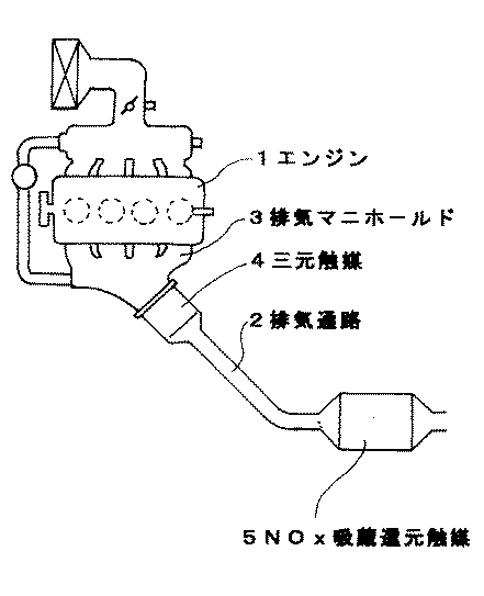
図1に示すように、リーンバーンエンジン1を搭載した車両の排気通路2の排気マニホールド3付近に上記三元触媒4を配置し、それから1m離れた下流側にNOx 吸蔵還元触媒5を配置した。そして10・15モードで運転してNOx 浄化率を測定し、初期浄化率として結果を表1に示す。
【0027】
また上記と同様にリーンバーンエンジン搭載車両に両触媒を配置し、市街地走行を模した運転条件にて200時間排ガスを流通させる耐久試験を行った。その後上記と同様にしてNOx 浄化率を測定し、耐久後浄化率として結果を表1に示す。
(実施例2)
γ−アルミナ粉末とチタニア粉末を重量比で1:1となるように混合し、ボールミルで5時間湿式混合した後、800℃で3時間焼成して担体粉末を調製した。この担体粉末の比表面積は100m2 /gである。
【0028】
この担体粉末を用いたこと以外は実施例1と同様に三元触媒を調製し、実施例1と同様のNOx 吸蔵還元触媒とともにリーンバーンエンジン搭載車両の排気通路に同様に配置して、同様に初期及び耐久後のNOx 浄化率を測定した。結果を表1に示す。
(実施例3)
γ−アルミナ粉末とチタニア粉末を重量比で1:1となるように混合し、ボールミルで5時間湿式混合した後、1000℃で3時間焼成して担体粉末を調製した。この担体粉末の比表面積は60m2 /gである。
【0029】
この担体粉末を用いたこと以外は実施例1と同様に三元触媒を調製し、実施例1と同様のNOx 吸蔵還元触媒とともにリーンバーンエンジン搭載車両の排気通路に同様に配置して、同様に初期及び耐久後のNOx 浄化率を測定した。結果を表1に示す。
(参考例1)
γ−アルミナ粉末とシリカ粉末を重量比で1:1となるように混合し、ボールミルで5時間湿式混合した後、1000℃で3時間焼成して担体粉末を調製した。この担体粉末の比表面積は60m2 /gである。
【0030】
この担体粉末を用いたこと以外は実施例1と同様に三元触媒を調製し、実施例1と同様のNOx 吸蔵還元触媒とともにリーンバーンエンジン搭載車両の排気通路に同様に配置して、同様に初期及び耐久後のNOx 浄化率を測定した。結果を表1に示す。
(実施例4)
γ−アルミナ粉末とジルコニア粉末を重量比で1:1となるように混合し、ボールミルで5時間湿式混合した後、1000℃で3時間焼成して担体粉末を調製した。この担体粉末の比表面積は60m2 /gである。
【0031】
この担体粉末を用いたこと以外は実施例1と同様に三元触媒を調製し、実施例1と同様のNOx 吸蔵還元触媒とともにリーンバーンエンジン搭載車両の排気通路に同様に配置して、同様に初期及び耐久後のNOx 浄化率を測定した。結果を表1に示す。
(比較例1)
γ−アルミナ粉末のみを担体粉末とした。この担体粉末の比表面積は180m2 /gである。そして、この担体粉末を用いたこと以外は実施例1と同様に三元触媒を調製し、実施例1と同様のNOx 吸蔵還元触媒とともにリーンバーンエンジン搭載車両の排気通路に同様に配置して、同様に初期及び耐久後のNOx 浄化率を測定した。結果を表1に示す。
【0032】
(比較例2)
三元触媒を用いず、実施例1と同様のNOx 吸蔵還元触媒のみをリーンバーンエンジン搭載車両の排気通路に実施例1同様に配置して、同様に初期及び耐久後のNOx 浄化率を測定した。結果を表1に示す。
【0033】
【表1】
【0034】
また実施例1〜3及び比較例1の比較より、三元触媒の担体の比表面積が小さくなるにつれて耐久後のNOx 浄化率が向上していることもわかる。なお、焼結温度が高くなるほど比表面積が小さくなるが、同時にチタニアとアルミナの複合酸化物の生成量も多くなるので、この効果は比表面積の効果と、原子レベルで複合化した複合酸化物としての効果が複合しているものと考えられる。
【0035】
さらに比較例2では初期のNOx 浄化率が実施例より低いことから、NOx 吸蔵還元触媒の上流側に三元触媒を配置した効果も明らかである。
【0036】
【発明の効果】
すなわち本発明の排ガス浄化装置によれば、空燃比がリーンからストイキ又はリッチに変化して排ガス中のHC濃度が増加しても、それをHC低減手段で充分に低減できるので、NOx 吸蔵還元触媒の触媒貴金属のHC被毒を抑制でき、耐久性が向上する。
【0037】
そしてHC低減手段によるSO2 の酸化が抑制されるため、NOx 吸蔵還元触媒とSOx との接触頻度が低下し、NOx 吸蔵元素の硫黄被毒が抑制される。したがって初期のNOx 浄化率を確保しつつ耐久後のNOx 浄化率の低下を抑制することができ、耐久性が向上する。
【図面の簡単な説明】
【図1】本発明の一実施例の排ガス浄化装置の系統図である。
【符号の説明】
1:エンジン 2:排気通路 3:排気マニホールド
4:三元触媒(HC低減手段) 5:NOx 吸蔵還元触媒[0001]
TECHNICAL FIELD OF THE INVENTION
The present invention relates to an exhaust gas purifying device, and more particularly, to an exhaust gas containing an excess amount of oxygen that is necessary to oxidize carbon monoxide (CO) and hydrocarbons (HC) contained in the exhaust gas. The present invention relates to an exhaust gas purifying apparatus that can efficiently purify nitrogen oxides (NO x ).
[0002]
[Prior art]
Conventionally, as an exhaust gas purifying catalyst of an automobile, a three-way catalyst for purifying exhaust gas by performing the reduction of CO and HC oxidation and NO x simultaneously is used. As such a catalyst, for example, a catalyst in which a support layer made of γ-alumina is formed on a heat-resistant carrier such as cordierite and a support noble metal such as Pt, Pd, and Rh is supported on the support layer is widely known. I have.
[0003]
By the way, the purification performance of such an exhaust gas purification catalyst greatly differs depending on the air-fuel ratio (A / F) of the engine. That is, the air-fuel ratio large, i.e. the more the oxygen content in the exhaust gas in the fuel concentration is lean lean side, the reduction reaction for purifying although NO x oxidation reactions of purifying CO and HC are active is inactive . Conversely small air-fuel ratio, that is the less oxygen content in the exhaust gas in the fuel concentration dark rich side, the oxidation reaction of CO and HC reduction reaction of but a inactive NO x becomes active.
[0004]
On the other hand, in the case of driving in an automobile, acceleration and deceleration are frequently performed in an automobile, and the air-fuel ratio frequently changes within a range from near stoichiometric (stoichiometric air-fuel ratio) to a rich state. In order to meet the demand for fuel economy in such traveling, it is necessary to operate on a lean side that supplies an air-fuel mixture with an excess of oxygen as much as possible, and lean burn engines have been used in recent years. Development of the catalyst is desirable to be able to sufficiently reduce and purify NO x even Therefore lean burn.
[0005]
Therefore the present applicant has proposed a previously exhaust gas purification catalyst is supported on a porous carrier such as alumina alkaline earth metal and Pt (NO x storage-reduction catalyst) (Japanese Patent Laid-Open No. 5-317652). According to this catalyst, NO x is absorbed in the alkaline earth metal in stoichiometric-rich atmosphere, because it is purified by reacting with reducing gases such as HC is released in the lean side, even in the lean-burn NO x has excellent purification performance.
[0006]
Note that, in the catalyst disclosed in JP-A-5-317652, for example, barium supported on a carrier as a single oxide, it NO by generating barium nitrate reacts with NO x (Ba (NO 3) 2) It is believed to occlude x .
Further, the heat-resistant inorganic oxide comprising a zeolite or alumina, also the NO x storage material and the exhaust gas purifying catalyst in which platinum is supported such that a rare earth element typified by an alkaline earth metal or lanthanum typified by barium knowledge (JP-A-5-168860 and JP-A-6-31139).
[0007]
More Hei 5-187230 discloses, place the NO x storage reduction catalyst as described above in an exhaust passage of a lean burn internal combustion engine capable, arranged HC reduction means comprising a three-way catalyst or oxidation catalyst in the upstream An exhaust gas purifying device has been proposed. According to this exhaust gas purifying device, HC is oxidized and removed on the upstream side, which is close to the engine in the exhaust passage and has a high temperature, and thus has excellent HC purifying performance in a low temperature region such as at the time of starting. Also since it is possible to suppress the HC to the catalyst noble metal is reduced the activity adsorbed, it is possible to maintain high the NO x purification rate over a long period of time.
[0008]
[Problems to be solved by the invention]
However, the exhaust gas contains SO 2 generated by burning sulfur (S) contained in the fuel, which is oxidized by the catalytic noble metal in an oxygen-excess atmosphere to form SO 3 . And it will be readily sulfate by water vapor also contained in the exhaust gas, they react like barium generate sulfites and sulfates, thereby the NO x storage material is found to degrade poisoned . The porous carrier such as alumina since the property that easily absorbs SO x, there is a problem that the sulfur poisoning is facilitated.
[0009]
Furthermore in the exhaust gas purifying device disclosed in JP-A 5-187230 Patent Publication, the amount of SO x to produce because the sulfur in the exhaust gas are oxidized by the HC reduction means upstream many, downstream of the NO x storage-reduction catalyst There is a problem that sulfur poisoning is further promoted.
When thus the NO x storage material becomes sulfite and sulfate by sulfur poisoning, it is difficult to occlude NO x longer, with the result the catalyst and the exhaust gas purifying apparatus, the purification of the NO x after the durability There was a problem that the performance was significantly reduced.
[0010]
In addition, since titania does not absorb SO 2 , an experiment was performed in which it was recalled that a titania carrier was used. As a result, SO 2 intact flows downstream without being absorbed by the titania, the degree of sulfur poisoning since only only SO 2 in direct contact with the catalyst noble metal is oxidized to be small revealed. However low initial activity in the titania carrier, it has been found that there is a critical problem that the purification performance of the NO x after the durability also remains low.
[0011]
The present invention has been made in view of such circumstances, while maintaining the initial of the NO x purification rate, and to prevent the deterioration of the NO x purifying performance after endurance.
[0012]
[Means for Solving the Problems]
Wherein the exhaust gas purifying apparatus of the present invention for solving the above-mentioned problems, can clean and combustible internal combustion engine and an exhaust passage lean air fuel ratio zone, the NO x in the exhaust gas of lean air fuel ratio zone which is installed in an exhaust passage and the NO x storage-reduction catalyst, with a, and HC reduction means including a the NO x storage located upstream of the reduction catalyst heat resistance made of a porous body carrier and the catalyst noble metal supported on a carrier in the exhaust passage In the exhaust gas purifying apparatus, a carrier of the HC reducing means is composed of a composite of alumina and at least one selected from titania and zirconia .
[0013]
BEST MODE FOR CARRYING OUT THE INVENTION
In the exhaust gas purifying apparatus of the present invention, and the HC reduction means and the NO x storage-reduction catalyst are arranged in this order on the downstream side from the upstream of the exhaust passage. Examples of the HC reducing means include a three-way catalyst, an oxidation catalyst, and the like, and include a carrier made of a heat-resistant porous body and a catalytic noble metal. The greatest feature of the present invention is that the carrier is composed of a composite of at least one selected from titania ( TiO 2 ) and zirconia ( ZrO 2 ) and alumina (Al 2 O 3 ).
[0014]
That is, by combining at least one selected from titania and zirconia with alumina, the carrier of the HC reducing means has an acid property. Therefore, the sulfur content (SO 2 ), which is acidic, is less likely to be adsorbed on the carrier, so that the generation of SO x is suppressed and the sulfur poisoning of the NO x storage material on the NO x storage reduction catalyst disposed downstream is reduced. Be suppressed.
[0015]
In addition, the carrier can reduce the specific surface area as compared with the case of using only alumina, so that the effect of making it difficult for sulfur to be adsorbed is added, so that the generation of SO x is further suppressed, and the sulfur of the NO x storage material is reduced. Poisoning is further suppressed. The use of a carrier having a reduced specific surface area also has the effect of increasing thermal stability. The specific surface area of the carrier is desirably about 10 to 100.
[0016]
In the case where at least one selected from titania and zirconia is combined with alumina to form a composite, it is preferable that the composite is formed in the following ratio.
Hereinafter, TiO 2 and ZrO 2 are collectively referred to as MO 2 . The compounding ratio of MO 2 and Al 2 O 3 is preferably in the range of M / Al = 5/95 to 50/50 in terms of the molar ratio converted to metal M and metal Al. When M / Al is less than 5/95, the NO x purification rate after durability decreases, and when M / Al exceeds 50/50, the initial NO x purification rate decreases and the NO x purification rate after durability decreases according to the value. It will be. A particularly desirable range is M / Al = 20/80 to 30/70.
[0017]
Further, it is desirable that MO 2 and Al 2 O 3 are combined at the smallest possible level. Thereby, generation of SO x can be further suppressed. For example, a composite oxide is more preferable than a simple mixture, and a composite at the atomic level is most preferable. In order to form a composite at the atomic level, there are methods such as a coprecipitation method and a sol-gel method.
[0018]
The HC reducing means can be configured by supporting a catalytic noble metal such as Pt, Rh, and Pd and / or a base metal such as Fe, Mn, and Cu on the carrier. For example, if the HC reducing means is a three-way catalyst, it is desirable that 0.05 to 20 g of the catalyst noble metal be supported per liter of the carrier. If the amount is less than 0.05 g, it becomes difficult to oxidize HC, and if the amount exceeds 20 g, the oxidizing action is saturated and the cost increases.
[0019]
The carrier of the HC reduction means may be formed into a honeycomb shape or a pellet shape by molding the carrier itself, or a configuration in which a carrier base material such as cordierite or a metal honeycomb shape is coated with the above composite powder. You can also.
The NO x storage reduction catalyst may be a conventional supporting a catalyst precious metal and the NO x storage element in the heat-resistant porous carrier similarly configured. Alumina, titania, silica, zirconia, silica-alumina and the like can be used as the heat-resistant porous carrier, and Pt, Rh, Pd and the like are used as the catalytic noble metal. Examples of the NO x storage element, Na, K, Cs, alkali metals such as Rb, Ba, Ca, alkaline earth metals such as Sr, Y, Ce, La, be used if desired rare earth elements such as Pr Can be.
[0020]
The loading amount of catalytic noble metal of the NO x storage-reduction catalyst, it is desirable to 0.05~20g bearing against the porous carrier 1 liter. If the amount is less than 0.05 g, reduction of NO x becomes difficult, and if the amount exceeds 20 g, the reduction action is saturated and the cost increases, which is not preferable. As the loading amount of the NO x storage material, it is desirable that 0.05 to 10 mol per mol of a porous carrier liter. If it is less than 0.05 mol, it is difficult to exhibit NO x storage capacity and it is difficult to reduce NO x , and if it exceeds 10 mol, the heat resistance will decrease.
[0021]
【Example】
Hereinafter, specific examples will be described.
(Example 1)
<Preparation of HC reduction means>
The γ-alumina powder and the titania powder were mixed at a weight ratio of 1: 1 and wet-mixed with a ball mill for 5 hours to prepare a carrier powder. The specific surface area of this carrier powder is 130 m 2 / g.
[0022]
A slurry is prepared by mixing 100 parts by weight of the carrier powder, 70 parts by weight of alumina sol (alumina 10% by weight), and 30 parts by weight of water, and a cordierite honeycomb carrier substrate is immersed in the slurry and drawn out. Excess slurry was blown off, dried at 120 ° C. for 1 hour, and baked at 500 ° C. for 1 hour to form a coat layer composed of TiO 2 —Al 2 O 3 . The coating layer is 200 g per liter of the honeycomb carrier substrate.
[0023]
Next, the honeycomb carrier on which the coating layer is formed is immersed in an aqueous solution of palladium nitrate having a predetermined concentration, pulled up and blown off extra droplets, dried at 120 ° C. for 1 hour, and baked at 250 ° C. for 1 hour to carry Pd. Then, a three-way catalyst as a means for reducing HC was prepared. The supported amount of Pd is 5 g per liter of the honeycomb carrier substrate.
<Preparation of NO x storage reduction catalyst>
100 parts by weight of γ-alumina powder, 70 parts by weight of alumina sol (alumina 10% by weight), 15 parts by weight of a 40% by weight aqueous solution of aluminum nitrate, and 30 parts by weight of water were mixed to prepare a coating slurry.
[0024]
Next, a cordierite honeycomb carrier base material was prepared, immersed in the above slurry, pulled up and blow off excess slurry, dried and fired at 600 ° C. for 1 hour to form an alumina coat layer, Was prepared. The coating amount is 120 g per liter of the volume of the honeycomb carrier substrate.
This carrier was immersed in an aqueous solution of dinitrodiammine platinum, pulled up to blow off excess water droplets, and dried at 250 ° C. to carry Pt. Then, the sample was immersed in an aqueous solution of rhodium nitrate to carry Rh in the same manner. The supported amounts of Pt and Rh are 2 g and 0.1 g per liter of the carrier, respectively.
[0025]
Next, an aqueous solution of barium acetate having a predetermined concentration was prepared, the above-mentioned Pt-Rh carrier was immersed, pulled up, dried by blowing off excess water droplets, and calcined at 600 ° C. for 1 hour to carry Ba. Next, it was immersed in an aqueous solution of lithium acetate having a predetermined concentration, pulled up, dried by blowing off excess water droplets, and fired at 600 ° C. for 1 hour to carry Li. Further, it was immersed in an aqueous solution of potassium acetate of a predetermined concentration, pulled up, dried by blowing off excess water droplets, and baked at 600 ° C. for 1 hour to carry K. Loading amount of each of the NO x storage element, honeycomb support substrate per liter of Ba is 0.3 mol, Li 0.1 mol, K is 0.1 mol.
[0026]
<Catalyst device and evaluation test>
As shown in FIG. 1, the three-way catalyst 4 is disposed near the exhaust manifold 3 of the exhaust passage 2 of a vehicle equipped with a lean burn engine 1, was placed the NO x storage-reduction catalyst 5 on it away from 1m downstream side . And operated at 10 · 15 mode to measure the NO x purification rate shown in Table 1 the results as the initial purification rate.
[0027]
In the same manner as above, a durability test was conducted in which both catalysts were arranged in a vehicle equipped with a lean burn engine and exhaust gas was circulated for 200 hours under operating conditions simulating urban driving. Then in the same manner as above to measure the NO x purification rate, the results shown in Table 1 as the durability after purification rate.
(Example 2)
The γ-alumina powder and the titania powder were mixed at a weight ratio of 1: 1 and wet-mixed with a ball mill for 5 hours, and then calcined at 800 ° C. for 3 hours to prepare a carrier powder. The specific surface area of this carrier powder is 100 m 2 / g.
[0028]
The support powder except for using similarly prepared a three-way catalyst as in Example 1, and similarly arranged in an exhaust passage of a lean-burn engine equipped vehicles with similar NO x storage reduction catalyst as in Example 1, the same the initial and the NO x purification ratio after durability was measured. Table 1 shows the results.
(Example 3)
The γ-alumina powder and the titania powder were mixed at a weight ratio of 1: 1 and wet-mixed in a ball mill for 5 hours, and then calcined at 1000 ° C. for 3 hours to prepare a carrier powder. The specific surface area of this carrier powder is 60 m 2 / g.
[0029]
Except that this carrier powder was used, a three-way catalyst was prepared in the same manner as in Example 1, and the same three-way catalyst was placed in the exhaust passage of a vehicle equipped with a lean burn engine together with the same NO x storage-reduction catalyst as in Example 1, and The NO x purification rates at the initial stage and after the endurance were measured. Table 1 shows the results.
( Reference Example 1 )
The γ-alumina powder and the silica powder were mixed at a weight ratio of 1: 1 and wet-mixed in a ball mill for 5 hours, and then calcined at 1000 ° C. for 3 hours to prepare a carrier powder. The specific surface area of this carrier powder is 60 m 2 / g.
[0030]
Except that this carrier powder was used, a three-way catalyst was prepared in the same manner as in Example 1, and the same three-way catalyst was placed in the exhaust passage of a vehicle equipped with a lean burn engine together with the same NO x storage-reduction catalyst as in Example 1, and The NO x purification rates at the initial stage and after the endurance were measured. Table 1 shows the results.
( Example 4 )
The γ-alumina powder and the zirconia powder were mixed at a weight ratio of 1: 1 and wet-mixed in a ball mill for 5 hours, and then calcined at 1000 ° C. for 3 hours to prepare a carrier powder. The specific surface area of this carrier powder is 60 m 2 / g.
[0031]
The support powder except for using similarly prepared a three-way catalyst as in Example 1, and similarly arranged in an exhaust passage of a lean-burn engine equipped vehicles with similar NO x storage reduction catalyst as in Example 1, the same the initial and the NO x purification ratio after durability was measured. Table 1 shows the results.
(Comparative Example 1)
Only γ-alumina powder was used as carrier powder. The specific surface area of this carrier powder is 180 m 2 / g. Then, except that this support powder with similarly prepared a three-way catalyst as in Example 1, and similarly arranged in an exhaust passage of a lean-burn engine equipped vehicles with similar NO x storage reduction catalyst of Example 1 It was measured in the same manner early and the NO x purification ratio after endurance. Table 1 shows the results.
[0032]
(Comparative Example 2)
Without using the three-way catalyst, disposed only similar NO x storage reduction catalyst of Example 1 in the same manner lean burn engine carried in an exhaust passage of a vehicle equipped with Example 1, likewise the initial and the NO x purification ratio after durability It was measured. Table 1 shows the results.
[0033]
[Table 1]
[0034]
Also from the comparison of Examples 1-3 and Comparative Example 1, it can also be seen that the the NO x purification ratio after durability as specific surface area of the support of the three-way catalyst is reduced is improved. The higher the sintering temperature, the smaller the specific surface area, but at the same time, the amount of the composite oxide of titania and alumina increases.Therefore, this effect is the effect of the specific surface area and the composite oxide compounded at the atomic level. It is considered that the effects of the above are combined.
[0035]
Further since the initial of the NO x purification rate Comparative Example 2 is lower than Example, the effect is also clear that arranging the the NO x storage three-way catalyst on the upstream side of the reduction catalyst.
[0036]
【The invention's effect】
That is, according to the exhaust gas purifying apparatus of the present invention, even if the air-fuel ratio is changed from lean to stoichiometric or rich increased HC concentration in the exhaust gas, since it can be sufficiently reduced by HC reduction means, NO x storage-reduction HC poisoning of the catalyst noble metal of the catalyst can be suppressed, and the durability is improved.
[0037]
Since the oxidation of SO 2 by the HC reducing means is suppressed, the frequency of contact between the NO x storage reduction catalyst and SO x is reduced, and the sulfur poisoning of the NO x storage element is suppressed. Thus while ensuring the initial of the NO x purification rate it is possible to suppress the reduction of the NO x purification ratio after durability, and durability is improved.
[Brief description of the drawings]
FIG. 1 is a system diagram of an exhaust gas purifying apparatus according to one embodiment of the present invention.
[Explanation of symbols]
1: Engine 2: exhaust passage 3: exhaust manifold 4: a three-way catalyst (HC reduction means) 5: NO x storage-reduction catalyst
Claims (1)
前記HC低減手段の前記担体がチタニア及びジルコニアから選ばれる少なくとも1種とアルミナとの複合体から構成されていることを特徴とする排ガス浄化装置。An internal combustion engine and an exhaust passage which can be burned in a lean air-fuel ratio range, and can purify the NO x storage reduction catalyst the NO x in the exhaust gas of lean air fuel ratio zone which is installed in the exhaust passage, said one of the exhaust passage in the exhaust gas purifying apparatus and a HC reduction means including a the NO x storage located upstream of the reduction catalyst heat resistance made of porous carrier and carrier carried on the catalytic noble metal,
An exhaust gas purifying apparatus, wherein the carrier of the HC reducing means is composed of a composite of alumina and at least one selected from titania and zirconia .
Priority Applications (1)
| Application Number | Priority Date | Filing Date | Title |
|---|---|---|---|
| JP33956296A JP3551346B2 (en) | 1996-12-19 | 1996-12-19 | Exhaust gas purification equipment |
Applications Claiming Priority (1)
| Application Number | Priority Date | Filing Date | Title |
|---|---|---|---|
| JP33956296A JP3551346B2 (en) | 1996-12-19 | 1996-12-19 | Exhaust gas purification equipment |
Publications (2)
| Publication Number | Publication Date |
|---|---|
| JPH10174844A JPH10174844A (en) | 1998-06-30 |
| JP3551346B2 true JP3551346B2 (en) | 2004-08-04 |
Family
ID=18328651
Family Applications (1)
| Application Number | Title | Priority Date | Filing Date |
|---|---|---|---|
| JP33956296A Expired - Lifetime JP3551346B2 (en) | 1996-12-19 | 1996-12-19 | Exhaust gas purification equipment |
Country Status (1)
| Country | Link |
|---|---|
| JP (1) | JP3551346B2 (en) |
Cited By (3)
| Publication number | Priority date | Publication date | Assignee | Title |
|---|---|---|---|---|
| WO2008081734A1 (en) | 2006-12-28 | 2008-07-10 | Toyota Jidosha Kabushiki Kaisha | Exhaust gas purifying apparatus for internal combustion engine |
| DE112007003177T5 (en) | 2006-12-28 | 2009-11-12 | Toyota Jidosha Kabushiki Kaisha, Toyota-shi | Exhaust emission control device for an internal combustion engine |
| DE112007003166T5 (en) | 2006-12-28 | 2009-11-26 | Toyota Jidosha Kabushiki Kaisha | Exhaust emission control apparatus for internal combustion engine |
Families Citing this family (2)
| Publication number | Priority date | Publication date | Assignee | Title |
|---|---|---|---|---|
| JP2002253968A (en) * | 2001-03-02 | 2002-09-10 | Toyota Central Res & Dev Lab Inc | Catalyst for purifying exhaust gas |
| JP6746097B2 (en) * | 2016-09-08 | 2020-08-26 | 株式会社豊田中央研究所 | NOx purification catalyst and NOx purification method using the same |
-
1996
- 1996-12-19 JP JP33956296A patent/JP3551346B2/en not_active Expired - Lifetime
Cited By (4)
| Publication number | Priority date | Publication date | Assignee | Title |
|---|---|---|---|---|
| WO2008081734A1 (en) | 2006-12-28 | 2008-07-10 | Toyota Jidosha Kabushiki Kaisha | Exhaust gas purifying apparatus for internal combustion engine |
| DE112007003177T5 (en) | 2006-12-28 | 2009-11-12 | Toyota Jidosha Kabushiki Kaisha, Toyota-shi | Exhaust emission control device for an internal combustion engine |
| DE112007003166T5 (en) | 2006-12-28 | 2009-11-26 | Toyota Jidosha Kabushiki Kaisha | Exhaust emission control apparatus for internal combustion engine |
| DE112007003177B4 (en) * | 2006-12-28 | 2012-07-19 | Toyota Jidosha K.K. | Exhaust emission control device for an internal combustion engine |
Also Published As
| Publication number | Publication date |
|---|---|
| JPH10174844A (en) | 1998-06-30 |
Similar Documents
| Publication | Publication Date | Title |
|---|---|---|
| JPH08168675A (en) | Catalyst for purifying exhaust gas | |
| JP3311012B2 (en) | Exhaust gas purification catalyst and exhaust gas purification method | |
| JPH0899034A (en) | Catalyst for purifying exhaust gas | |
| JPH0788371A (en) | Catalyst for purifying exhaust gas and method therefor | |
| EP1188908A2 (en) | Exhaust gas purifying system | |
| WO2000000283A1 (en) | Catalyst for exhaust gas purification, process for producing the same, and method of purifying exhaust gas | |
| JP3409894B2 (en) | Exhaust gas purification catalyst and exhaust gas purification method | |
| JPH09215922A (en) | Catalyst for purifying exhaust gas | |
| JP3821343B2 (en) | Exhaust gas purification device | |
| JP3685463B2 (en) | Exhaust gas purification catalyst | |
| JP3789231B2 (en) | Exhaust gas purification catalyst | |
| JP2002326033A (en) | Catalyst for cleaning exhaust gas | |
| JPH08117600A (en) | Catalyst for purifying exhaust gas and preparation of catalyst | |
| JP3374999B2 (en) | Exhaust gas purification catalyst | |
| JP3555694B2 (en) | Exhaust gas purification device | |
| JPH07108172A (en) | Exhaust gas purifying catalyst and production therefor | |
| JP3551346B2 (en) | Exhaust gas purification equipment | |
| JP3224054B2 (en) | Exhaust gas purification method | |
| JP3800200B2 (en) | Exhaust gas purification method and exhaust gas purification catalyst | |
| JPH07132226A (en) | Catalyst for purifying exhaust gas | |
| JP3664201B2 (en) | Exhaust gas purification catalyst | |
| JPH07171349A (en) | Exhaust gas purification | |
| JP3775080B2 (en) | Exhaust gas purification catalyst | |
| JP3839860B2 (en) | Exhaust gas purification catalyst and exhaust gas purification method | |
| JP3320855B2 (en) | Exhaust gas purification method |
Legal Events
| Date | Code | Title | Description |
|---|---|---|---|
| A977 | Report on retrieval |
Free format text: JAPANESE INTERMEDIATE CODE: A971007 Effective date: 20040116 |
|
| A131 | Notification of reasons for refusal |
Free format text: JAPANESE INTERMEDIATE CODE: A131 Effective date: 20040123 |
|
| A521 | Written amendment |
Free format text: JAPANESE INTERMEDIATE CODE: A523 Effective date: 20040305 |
|
| TRDD | Decision of grant or rejection written | ||
| A01 | Written decision to grant a patent or to grant a registration (utility model) |
Free format text: JAPANESE INTERMEDIATE CODE: A01 Effective date: 20040402 |
|
| A61 | First payment of annual fees (during grant procedure) |
Free format text: JAPANESE INTERMEDIATE CODE: A61 Effective date: 20040415 |
|
| R150 | Certificate of patent or registration of utility model |
Free format text: JAPANESE INTERMEDIATE CODE: R150 |
|
| FPAY | Renewal fee payment (event date is renewal date of database) |
Free format text: PAYMENT UNTIL: 20080514 Year of fee payment: 4 |
|
| FPAY | Renewal fee payment (event date is renewal date of database) |
Free format text: PAYMENT UNTIL: 20090514 Year of fee payment: 5 |
|
| FPAY | Renewal fee payment (event date is renewal date of database) |
Free format text: PAYMENT UNTIL: 20100514 Year of fee payment: 6 |
|
| FPAY | Renewal fee payment (event date is renewal date of database) |
Free format text: PAYMENT UNTIL: 20110514 Year of fee payment: 7 |
|
| FPAY | Renewal fee payment (event date is renewal date of database) |
Free format text: PAYMENT UNTIL: 20110514 Year of fee payment: 7 |
|
| FPAY | Renewal fee payment (event date is renewal date of database) |
Free format text: PAYMENT UNTIL: 20120514 Year of fee payment: 8 |
|
| FPAY | Renewal fee payment (event date is renewal date of database) |
Free format text: PAYMENT UNTIL: 20120514 Year of fee payment: 8 |
|
| FPAY | Renewal fee payment (event date is renewal date of database) |
Free format text: PAYMENT UNTIL: 20130514 Year of fee payment: 9 |
|
| FPAY | Renewal fee payment (event date is renewal date of database) |
Free format text: PAYMENT UNTIL: 20140514 Year of fee payment: 10 |
|
| EXPY | Cancellation because of completion of term |