JP3542099B2 - Tractor work controls - Google Patents
Tractor work controls Download PDFInfo
- Publication number
- JP3542099B2 JP3542099B2 JP36036697A JP36036697A JP3542099B2 JP 3542099 B2 JP3542099 B2 JP 3542099B2 JP 36036697 A JP36036697 A JP 36036697A JP 36036697 A JP36036697 A JP 36036697A JP 3542099 B2 JP3542099 B2 JP 3542099B2
- Authority
- JP
- Japan
- Prior art keywords
- load
- vehicle speed
- detected
- sensor
- work
- Prior art date
- Legal status (The legal status is an assumption and is not a legal conclusion. Google has not performed a legal analysis and makes no representation as to the accuracy of the status listed.)
- Expired - Fee Related
Links
Images




Landscapes
- Lifting Devices For Agricultural Implements (AREA)
Description
【0001】
【発明の属する技術分野】
本発明は、自走機体に昇降操作自在に連結された対地作業用作業装置の牽引負荷を検出する負荷センサーと、制御目標負荷を設定する負荷設定手段と、前記負荷センサーによる検出負荷が前記負荷設定手段によって設定された設定制御目標負荷になるように作業装置を昇降操作する作業深さ制御手段とが備えられているトラクターの作業用制御装置に関する。
【0002】
【従来の技術】
上記トラクターの作業用制御装置は、プラウ装置を連結して耕耘作業するなどの際、所望の作業深さを負荷設定手段によって牽引負荷として設定し、トラクターが前後に傾斜することがあっても、作業深さ制御手段による作業装置の昇降操作により、作業深さを所望深さに維持しながら作業できるようにされたものである。
この種トラクターにおいて、車速が変化すると、作業装置のトラクターに対する連結高さが一定で作業深さが同じであっても、作業装置を牽引する速度が変化することから、トラクターに掛かる牽引負荷が変化する。この場合でも、従来は、トラクターに掛かる実際の牽引負荷と、負荷設定手段によって設定された設定制御目標負荷とに基づいて作業装置の昇降制御が行われるようになっていた。
【0003】
【発明が解決しようとする課題】
従来、作業時に高速走行してもハンドルが取られにくいからアクセルアップするとか、スリップしやすいからアクセルダウンするなど、車速を変更すると、作業深さが所望深さと変化することがあった。すなわち、車速を上昇側に変更した場合、トラクターに掛かる牽引負荷が増加することから作業装置の上昇制御が実行されて作業深さが所望深さよりも浅くなることがあり、車速を下降側に変更した場合、トラクターに掛かる牽引負荷が減少することから作業装置の下降制御が実行されて作業深さが所望深さよりも深くなることがあった。
本発明の目的は、車速変更しても作業深さを極力所望深さに維持しながら作業できるトラクターの作業用制御装置を提供することにある。
【0004】
【課題を解決するための手段】
請求項1による発明の構成、作用はつぎのとおりである。
【0005】
〔構成〕
自走機体に昇降操作自在に連結された対地作業用作業装置の牽引負荷を検出する負荷センサーと、制御目標負荷を設定する負荷設定手段と、前記負荷センサーによる検出負荷が前記負荷設定手段によって設定された設定制御目標負荷になるように作業装置を昇降操作する作業深さ制御手段とが備えられているトラクターの作業用制御装置において、
車速を検出する車速センサーと、この車速センサーからの情報に基づいて作動する目標負荷調整手段とを備えるとともに、車速センサーによる検出車速が設定車速より速いと、目標負荷調整手段が負荷設定手段による設定制御目標負荷を増加側に調整してこの調整制御目標負荷を前記負荷設定手段による設定制御目標負荷として前記作業深さ制御手段に出力するように構成してある。
【0006】
〔作用〕
作業装置による作業を行う際に、その作業が可能となるようにトラクターに備えさせねばならない走行速度のうちの最低速度を前記設定車速として設定する。すると、アクセル操作などで車速変更されて車速が設定速度より高速側になると、負荷センサーによる検出負荷が設定速度で走行されているときの検出負荷より増加する。このとき、目標負荷調整手段が負荷設定手段によって設定されている設定制御目標負荷を増加側に調整してこの調整制御目標負荷を作業深さ制御手段に出力し、作業深さ制御手段は負荷センサーによる増加検出負荷が負荷設定手段による調整制御目標負荷になるように作業装置を昇降操作することになる。これにより、車速変化に伴う目標負荷調整手段による設定制御目標負荷の調整を適切に行わせると、車速を変更されて負荷センサーによる検出負荷が変化しても、作業装置の昇降操作が実行されないようになるとか、実行されても作業深さが大幅に変化しないように昇降ストロークが小さいものになる。
【0007】
請求項2による発明の構成、作用はつぎのとおりである。
【0008】
〔構成〕
自走機体に昇降操作自在に連結された対地作業用作業装置の牽引負荷を検出する負荷センサーと、制御目標負荷を設定する負荷設定手段と、前記負荷センサーによる検出負荷が前記負荷設定手段によって設定された設定制御目標負荷になるように作業装置を昇降操作する作業深さ制御手段とが備えられているトラクターの作業用制御装置において、
車速を検出する車速センサーと、この車速センサーからの情報に基づいて作動する検出負荷調整手段とを備えるとともに、車速センサーによる検出車速が設定車速より速いと、検出負荷調整手段が負荷センサーによる検出負荷を減少側に調整してこの調整検出負荷を前記負荷センサーによる検出負荷として前記作業深さ制御手段に出力するように構成してある。
【0009】
〔作用〕
作業装置による作業を行う際に、その作業が可能となるようにトラクターに備えさせねばならない走行速度のうちの最低速度を前記設定車速として設定する。すると、アクセル操作などで車速変更されて車速が設定速度より高速側になると、負荷センサーによる検出負荷が設定速度で走行されているときの検出負荷より増加する。このとき、検出負荷調整手段が負荷センサーによる検出負荷を減少側に調整してこの調整検出負荷を作業深さ制御手段に出力し、作業深さ制御手段は調整検出負荷が負荷設定手段による設定制御目標負荷になるように作業装置を昇降操作することになる。これにより、車速変化に伴う検出負荷調整手段による検出負荷の調整を適切に行わせると、車速を変更されて負荷センサーによる検出負荷が変化しても、作業装置の昇降操作が実行されないようになるとか、実行されても作業深さが大幅に変化しないように昇降ストロークが小さいものになる。
【0010】
請求項1及び2による発明の効果はつぎのとおりである。
【0011】
〔効果〕
車速が作業用最低速度よりも高速側に変更されたアップ側やダウン側に変更されて負荷センサーによる検出負荷が作業用最低速度のときとは異なるものになっても、これに伴う設定制御目標負荷又は検出負荷の調整を適切に行わせて作業深さが変化しないとか、大幅に変化しないようにしながら作業することが可能になり、車体のピッチングにかかわらず作業深さが極力設定深さになる仕上がりのよい作業を極力高速走行して能率よくできる。
【0012】
【発明の実施の形態】
図1に示すように、左右一対の駆動及び揺動操向自在な前車輪1,1と、左右一対の駆動自在な後車輪2,2とによって自走し、前車輪1を操向操作するステアリングハンドル3、運転座席4などを有する運転部を備える機体の後部に、左右一対のリフトアーム5,5を油圧式のリフトシリンダ6によって上下に揺動操作できるように備えさせるとともに、連結した作業装置に回転動力を伝達する動力取出し軸7を備えさせて、トラクターを構成してある。このトラクターの後部に、複数のプラウ8a・によって耕耘作業するプラウ装置8をリンク機構9を介して連結するとともに、一対のリフトアーム5,5が一方のリフトアーム5に連結するリフトロッド10と、他方のリフトアーム5に連結するプラウ装置ローリング操作用シリンダ11とを介してリンク機構9を前記自走機体に対して上下に揺動操作してプラウ装置8を昇降操作するように構成し、もって、トラクターにプラウ装置8を牽引させながら走行させることによって耕耘作業するように、かつ、リフトシリンダ6を操作することによってプラウ装置8をトラクターに対して昇降操作するように乗用型耕耘装置を構成してある。
【0013】
前記自走機体の後部を形成する走行及び作業用ミッションケース12の内部に、プラウ装置8の牽引負荷を検出する負荷センサー13、及び、トラクターの車速を検出する車速センサー14を設け、運転部に位置する運転パネルに、負荷設定手段15を耕深設定用に設け、図2に示す如く前記各センサー13,14及び負荷設定手段15に連係させた制御装置16をトラクターに搭載するとともに前記リフトシリダ6の制御弁機構17に連係させて、作業用制御装置を構成してある。この作業用制御装置は、所望の耕耘深さを負荷設定手段15によって設定し、トラクターが前後に傾斜したり、トラクターの走行速度を変更したりしてもプラウ装置8による耕耘深さを所望深さに維持しながら作業することを可能にするものであり、詳しくは次の如く構成してある。
【0014】
負荷センサー13は、前記リンク機構9を構成する左右一対のロワーリンク9a,9aの前端側を回動自在に支持させるとともに前記ミッションケース12を機体横方向に貫通させてこのミッションケース12に各ロワーリンク9a,9aを上下揺動自在に連結させてあるリンク支軸18に作用する歪みセンサーによって構成してある。すなわち、プラウ装置8の牽引負荷が作用することによってリンク支軸18にたわみが発生する。そのたわみによるリンク支軸18の変位を、この変位に起因して歪みセンサーに起こる出力電圧の変化で検出するようにしてある。つまり、負荷センサー13は、リンク支軸18のたわみによる変位を牽引負荷として検出し、この検出負荷を電気信号にして制御装置16に出力する。
【0015】
車速センサー14は、前記ミッションケース12の内部に設けてある走行用トランスミッションが回転出力を後輪用差動機構に伝達するように備えている出力軸に作用する回転センサーで成り、前記出力軸の回転数に基づいてトラクターの走行速度を検出し、この検出車速Vを電気信号にして制御装置16に出力する。
【0016】
前記負荷設定手段15は、ダイヤル15aを回転操作することによって具備する電気抵抗が変化する可変抵抗器によって構成してある。すなわち、ダイヤル15aを回転操作して所望の耕耘深さを設定する。すると、負荷設定手段15は、その所望耕耘深さに対応する牽引負荷を制御目標負荷として設定し、この設定制御目標負荷を電気信号にして制御装置16に出力する。
【0017】
前記制御弁機構17は、リフトシリンダ6をプラウ装置8の上昇側に制御するアップ電磁比例流量制御弁と、プラウ装置8の下降側に制御するダウン電磁比例流量制御弁とを備え、制御装置16からの指令としての電気信号に基いて両比例流量制御弁を操作してリフトシンダ6を制御するように構成してある。
【0018】
前記制御装置16は、マイクロコンピュータで成り、前記各センサー13,14及び負荷設定手段15からの情報と、図3に示す制御フローとに基づいて作動するように構成してある。
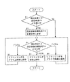
すなわち、ステップ#1〜3に示すように、車速センサー14によって検出されている検出車速Vが、プラウ装置8による耕耘が可能となるようにトラクターに備えさせねばならない走行速度のうちの最低速度のものとして設定してある設定車速VAより速いか否かを判断し、検出車速Vが設定車速VAより速いと判断した場合には、負荷設定手段15によって設定された設定制御目標負荷FAを検出車速Vと設定車速VAとの差に対応する分だけ増加側に変更調整し、この調整設定制御目標負荷FAと、負荷センサー13によって検出されている検出負荷Fとを比較する。ステップ#1において検出車速Vが前記設定車速VAより速くないと判断した場合には、負荷設定手段よって設定された設定制御目標負荷FAを変更しないで採用し、その設定制御目標負荷FAと負荷センサー13によって検出されている検出負荷Fとを比較する。ステップ#3において、負荷センサー13による検出負荷Fが設定制御目標負荷FAに等しいと判断した場合には、ステップ#4に示すように、制御機構17にリフトシリンダ6を停止させるべき信号を出力することによってリフトシリンダ6を停止状態に操作させる。ステップ#3において負荷センサー13による検出負荷Fが設定制御目標負荷FAより大であると判断した場合には、ステップ#5に示すように、制御機構17にリフトシリンダ6を上昇側に制御させるべき信号を出力することにより、負荷センサー13による検出負荷Fが設定制御目標負荷FAに等しくなるまでリフトシリンダ6をプラウ装置8の上昇側に操作させる。ステップ#3において負荷センサー13による検出負荷Fが設定制御目標負荷FAより小であると判断した場合には、ステップ#6に示すように、制御機構17にリフトシリンダ6を下降側に制御させるべき信号を出力することにより、負荷センサー13による検出負荷Fが設定制御目標負荷FAに等しくなるまでリフトシリンダ6をプラウ装置8の下降側に操作させる。
【0019】
すなわち、ステップ#1,2により、車速センサー14からの情報に基づいて自動的に作動する目標負荷調整手段18を構成し、ステップ#3〜6によって作業深さ制御手段19を構成してあり、目標負荷調整手段18は、負荷設定手段15によって設定された設定制御目標負荷を車速センサー14による検出車速Vに基づいて次の如く調整し、この調整制御目標負荷を負荷設定手段15による設定制御目標負荷FAとして作業深さ制御手段19に出力する。すなわち、車速センサー14による検出車速Vが、プラウ装置8による耕耘作業を行うのに必要なトラクター走行速度のうちの最低速度として予め設定してある前記設定車速VA以下である場合には、負荷設定手段15によって設定された設定制御目標負荷を増加側にも減少側にも変更せず、この無調整の設定制御目標負荷を負荷設定手段15による設定制御目標負荷FAとして作業深さ制御手段19に出力する。車速センサー14による検出車速Vが前記設定車速FAよりも速い場合には、負荷設定手段15によって設定された設定制御目標負荷を、車速センサー14による検出車速Vと設定車速VAとの差に対応する分だけ増加したものに変更調整し、この調整目標負荷を負荷設定手段15による設定制御目標負荷FAとして作業深さ制御手段19に出力する。すなわち、車速センサー14による検出車速Vが前記設定車速VAよりも高速側になった場合、負荷センサー13によって検出される検出負荷は検出車速Vが設定車速VAであるときより増加したものになるが、この検出負荷増加に起因するプラウ装置8の昇降制御が実行されることを防止するように、負荷設定手段15によって設定されている設定制御目標負荷を、負荷センサー13による検出負荷が車速アップによって増加している分に対応する分だけ増加側に変更調整する。そして、作業深さ制御手段19は、目標負荷調整手段18から出力される制御目標負荷FAを負荷設定手段15による設定制御目標負荷FAとして採用し、この設定制御目標負荷FAと、負荷センサー13による検出負荷Fとが等しくなるようにプラウ装置8を昇降操作する。
【0020】
図4は、別の実施形態を備える作業用制御装置を示す。この作業用制御装置も、所望の耕耘深さを負荷設定手段15によって設定し、トラクターが前後に傾斜したり、トラクターの走行速度を変更したりしてもプラウ装置8による耕耘深さを所望深さに維持しながら作業することを可能にするものであり、詳しくは次の如く構成してある。
【0021】
負荷センサー13、車速センサー14、負荷設定手段15、制御弁機構17のぞれぞれは、図1及び図2に示すものと同様に構成してある。
【0022】
前記制御装置16は、マイクロコンピュータで成り、前記各センサー13,14及び負荷設定手段15からの情報と、図5に示す制御フローとに基づいて作動するように構成してある。
すなわち、ステップ#1〜3に示すように、車速センサー14によって検出されている検出車速Vが、プラウ装置8による耕耘が可能となるようにトラクターに備えさせねばならない走行速度のうちの最低速度のものとして設定してある設定車速VAより速いか否かを判断し、検出車速Vが設定車速VAより速いと判断した場合には、負荷センサー13によって検出されている検出負荷を検出車速Vと設定車速VAとの差に対応する分だけ減少側に変更調整し、この調整検出負荷FBと、負荷設定手段15によって設定されている設定制御目標負荷FAとを比較する。ステップ#1において検出車速Vが前記設定車速VAより速くないと判断した場合には、負荷センサー13によって検出されている検出負荷を変更しないで採用し、その検出負荷FBと、負荷設定手段15によって設定されている設定制御目標負荷FAとを比較する。ステップ#3において、検出負荷FBが設定制御目標負荷FAに等しいと判断した場合には、ステップ#4に示すように、制御機構17にリフトシリンダ6を停止させるべき信号を出力することによってリフトシリンダ6を停止状態に操作させる。ステップ#3において検出負荷FBが設定制御目標負荷FAより大であると判断した場合には、ステップ#5に示すように、制御機構17にリフトシリンダ6を上昇側に制御させるべき信号を出力することにより、検出負荷FBが設定制御目標負荷FAに等しくなるまでリフトシリンダ6をプラウ装置8の上昇側に操作させる。ステップ#3において検出負荷FBが設定制御目標負荷FAより小であると判断した場合には、ステップ#6に示すように、制御機構17にリフトシリンダ6を下降側に制御させるべき信号を出力することにより、検出負荷FBが設定制御目標負荷FAに等しくなるまでリフトシリンダ6をプラウ装置8の下降側に操作させる。
【0023】
すなわち、ステップ#1,2により、車速センサー14からの情報に基づいて自動的に作動する検出負荷調整手段20を構成し、ステップ#3〜6によって作業深さ制御手段19を構成してあり、検出負荷調整手段20は、負荷センサー13によって検出された検出負荷を車速センサー14による検出車速Vに基づいて次の如く調整し、この調整検出負荷を負荷センサー13による検出負荷FBとして作業深さ制御手段19に出力する。すなわち、車速センサー14による検出車速Vが、プラウ装置8による耕耘作業を行うのに必要なトラクター走行速度のうちの最低速度として予め設定してある前記設定車速VA以下である場合には、負荷センサー13によって検出された検出負荷を増加側にも減少側にも変更せず、この無調整の検出負荷を負荷センサー13による検出負荷FBとして作業深さ制御手段19に出力する。車速センサー14による検出車速Vが前記設定車速FAよりも速い場合には、負荷センサー13によって検出された検出負荷を、車速センサー14による検出車速Vと設定車速VAとの差に対応する分だけ減少したものに変更調整し、この調整検出負荷を負荷センサー13による検出負荷FBとして作業深さ制御手段19に出力する。すなわち、車速センサー14による検出車速Vが前記設定車速VAよりも高速側になった場合、負荷センサー13によって検出される検出負荷は検出車速Vが設定車速VAであるときより増加したものになるが、この検出負荷増加に起因するプラウ装置8の昇降制御が実行されることを防止するように、負荷センサー13によって検出されている検出負荷を車速増加によって増加した分だけ減少側に変更調整する。そして、作業深さ制御手段19は、検出負荷調整手段20から出力される検出負荷FBを負荷センサー13による検出負荷FBとして採用し、この検出負荷FBが負荷設定手段15による設定制御目標負荷FAになるようにプラウ装置8を昇降操作する。
【0024】
図2及び図4に示す下限設定センサー21は、前記リフトアーム5のミッションケース12に対する取り付け角度を検出するようにリフトアーム5に連動させた回転ポテンショメータで成り、プラウ装置8が下降操作されて限界に到達すると、プラウ装置8のそれ以上の下降操作を停止させるべき信号を制御装置16に出力するものである。図2及び図4に示す昇降操作器22は、ダイヤル22aを回転操作することによって具備する電気抵抗が変化する可変抵抗器で成り、プラウ装置8を負荷センサー13による検出負荷に優先して上げ操作させるべき信号を制御装置16に出力したり、上げ操作されたプラウ装置8を元の下降位置に下降させるべき信号を制御装置16に出力したりするものである。すなわち、圃場端で機体旋回させる際など、ダイヤル22aを回転操作し、プラウ装置8を下降作業位置から上昇非作業位置に上げ操作したり、上昇非作業位置から下降作業位置に下げ操作したりするものである。
【0025】
〔別実施形態〕
プラウ装置8に替え、暗渠を作成するサブソイラーなどを連結する際にも本発明は適用できる。したがって、これらプラウ装置8、サブソイラーなどを総称して対地作業用作業装置8と呼称する。
【図面の簡単な説明】
【図1】乗用型耕耘機全体の側面図
【図2】作業用制御装置のブロック図
【図3】プラウ装置昇降制御用フロー図
【図4】別の実施形態を備える作業用制御装置のブロック図
【図5】別の実施形態を備える作業用制御装置のプラウ装置昇降制御用フロー図
【符号の説明】
8 作業装置
13 負荷センサー
14 車速センサー
15 負荷設定手段
18 目標負荷調整手段
19 作業深さ制御手段
20 検出負荷調整手段[0001]
TECHNICAL FIELD OF THE INVENTION
The present invention provides a load sensor for detecting a towing load of a ground work device connected to a self-propelled body so as to be able to move up and down, a load setting means for setting a control target load, and the load detected by the load sensor being the load. The present invention relates to a work control device for a tractor, provided with work depth control means for raising and lowering a work device so as to reach a set control target load set by a setting means.
[0002]
[Prior art]
The work control device of the tractor, such as when tilling work by connecting the plow device, set the desired work depth as a towing load by the load setting means, even if the tractor may be tilted back and forth, By operating the working device up and down by the working depth control means, it is possible to work while maintaining the working depth at a desired depth.
In this type of tractor, when the vehicle speed changes, the towing load on the tractor changes because the speed at which the work equipment is towed changes, even if the connection height of the work equipment to the tractor is constant and the work depth is the same. I do. Even in this case, conventionally, the lifting / lowering control of the working device has been performed based on the actual towing load applied to the tractor and the set control target load set by the load setting means.
[0003]
[Problems to be solved by the invention]
Conventionally, when the vehicle speed is changed, such as when the steering wheel is hard to be taken and the accelerator is raised even when traveling at a high speed, or when the vehicle is easily slipped and the accelerator is lowered, the working depth sometimes changes to a desired depth. That is, when the vehicle speed is changed to the ascending side, since the towing load applied to the tractor increases, the ascent control of the working device is executed, and the working depth may be smaller than the desired depth, and the vehicle speed is changed to the descending side. In such a case, since the towing load applied to the tractor is reduced, the lowering control of the working device is performed, and the working depth may be deeper than the desired depth.
An object of the present invention is to provide a tractor operation control device that can operate while maintaining the operation depth at a desired depth as much as possible even when the vehicle speed is changed.
[0004]
[Means for Solving the Problems]
The structure and operation of the invention according to
[0005]
〔Constitution〕
A load sensor for detecting a towing load of the work equipment for ground work coupled to the self-propelled body so as to be able to move up and down, a load setting means for setting a control target load, and a load detected by the load sensor set by the load setting means. Working depth control means for raising and lowering the working device so as to reach the set control target load in the tractor work control device,
A vehicle speed sensor for detecting a vehicle speed, and a target load adjusting device that operates based on information from the vehicle speed sensor. When the vehicle speed detected by the vehicle speed sensor is higher than the set vehicle speed, the target load adjusting device sets the target load by the load setting device. The control target load is adjusted to the increasing side, and the adjusted control target load is output to the work depth control means as the control target load set by the load setting means.
[0006]
[Action]
When the work is performed by the work device, a minimum speed among the traveling speeds that must be provided to the tractor so that the work can be performed is set as the set vehicle speed. Then, when the vehicle speed is changed to a speed higher than the set speed by changing the vehicle speed by an accelerator operation or the like, the load detected by the load sensor is increased from the load detected when the vehicle is running at the set speed. At this time, the target load adjusting means adjusts the set control target load set by the load setting means to the increasing side, and outputs the adjusted control target load to the work depth control means. The working device is moved up and down so that the increase detection load due to the load setting means becomes the adjustment control target load. With this, when the set load is appropriately adjusted by the target load adjusting means according to the change in the vehicle speed, even if the vehicle speed is changed and the load detected by the load sensor changes, the lifting / lowering operation of the working device is not executed. Or the lifting stroke is small so that the working depth does not change significantly even if executed.
[0007]
The structure and operation of the invention according to
[0008]
〔Constitution〕
A load sensor for detecting a towing load of the work equipment for ground work coupled to the self-propelled body so as to be able to move up and down, a load setting means for setting a control target load, and a load detected by the load sensor set by the load setting means. Working depth control means for raising and lowering the working device so as to reach the set control target load in the tractor work control device,
A vehicle speed sensor for detecting a vehicle speed; and a detection load adjusting unit that operates based on information from the vehicle speed sensor. When the vehicle speed detected by the vehicle speed sensor is faster than a set vehicle speed, the detection load adjusting unit detects the load detected by the load sensor. Is adjusted to the decreasing side, and the adjustment detection load is outputted to the work depth control means as a detection load by the load sensor.
[0009]
[Action]
When the work is performed by the work device, a minimum speed among the traveling speeds that must be provided to the tractor so that the work can be performed is set as the set vehicle speed. Then, when the vehicle speed is changed to a speed higher than the set speed by changing the vehicle speed by an accelerator operation or the like, the load detected by the load sensor is increased from the load detected when the vehicle is running at the set speed. At this time, the detected load adjusting means adjusts the load detected by the load sensor to the decreasing side, and outputs the adjusted detected load to the work depth control means. The working device is moved up and down to achieve the target load. Accordingly, when the detection load is appropriately adjusted by the detection load adjustment unit in accordance with the vehicle speed change, even if the vehicle speed is changed and the detection load by the load sensor changes, the lifting / lowering operation of the working device is not executed. In other words, the elevating stroke is small so that the working depth does not change significantly even if it is executed.
[0010]
The effects of the invention according to
[0011]
〔effect〕
Even if the vehicle speed is changed to a higher speed side or a lower speed side than the minimum working speed, and the load detected by the load sensor is different from that at the minimum working speed, the setting control target associated with this It is possible to work while the work depth does not change by making appropriate adjustment of the load or the detected load, or it is possible to work while keeping the work depth unchanged, and the work depth is set to the set depth as much as possible regardless of the pitching of the vehicle body Highly efficient work can be performed at high speed as much as possible.
[0012]
BEST MODE FOR CARRYING OUT THE INVENTION
As shown in FIG. 1, a pair of left and right drive and swing steerable
[0013]
A
[0014]
The
[0015]
The
[0016]
The load setting means 15 is constituted by a variable resistor whose electric resistance changes by rotating the
[0017]
The control valve mechanism 17 includes an up electromagnetic proportional flow control valve for controlling the
[0018]
The
That is, as shown in
[0019]
That is, steps # 1 and # 2 constitute a target load adjusting means 18 which automatically operates based on information from the
[0020]
FIG. 4 shows a working control device according to another embodiment. This work control device also sets the desired tillage depth by the load setting means 15 and adjusts the tillage depth by the plow device 8 to the desired depth even if the tractor is tilted back and forth or the traveling speed of the tractor is changed. It is possible to work while maintaining the same, and is configured in detail as follows.
[0021]
Each of the
[0022]
The
That is, as shown in
[0023]
That is, the
[0024]
The lower
[0025]
[Another embodiment]
The present invention can be applied to connecting a subsoiler or the like for creating a culvert instead of the plow device 8. Therefore, the plow device 8, the subsoiler, and the like are collectively referred to as a work device for ground work.
[Brief description of the drawings]
FIG. 1 is a side view of an entire riding type cultivator. FIG. 2 is a block diagram of a work control device. FIG. 3 is a flowchart of a plow device lifting control. FIG. 4 is a block of a work control device having another embodiment. FIG. 5 is a flowchart of a plow device lifting / lowering control of a working control device having another embodiment.
8 Working
Claims (2)
車速を検出する車速センサーと、この車速センサーからの情報に基づいて作動する目標負荷調整手段とを備えるとともに、車速センサーによる検出車速が設定車速より速いと、目標負荷調整手段が負荷設定手段による設定制御目標負荷を増加側に調整してこの調整制御目標負荷を前記負荷設定手段による設定制御目標負荷として前記作業深さ制御手段に出力するように構成してあるトラクターの作業用制御装置。A load sensor for detecting a towing load of the ground-working work device movably connected to the self-propelled body, a load setting unit for setting a control target load, and a load detected by the load sensor set by the load setting unit. Work depth control means for lifting and lowering the work device so that the set control target load, the work control device of the tractor,
A vehicle speed sensor for detecting a vehicle speed, and a target load adjusting device that operates based on information from the vehicle speed sensor. When the vehicle speed detected by the vehicle speed sensor is higher than the set vehicle speed, the target load adjusting device sets the target load by the load setting device. A work control device for a tractor, wherein a control target load is adjusted to an increasing side, and the adjusted control target load is output to the work depth control means as a control load set by the load setting means.
車速を検出する車速センサーと、この車速センサーからの情報に基づいて作動する検出負荷調整手段とを備えるとともに、車速センサーによる検出車速が設定車速より速いと、検出負荷調整手段が負荷センサーによる検出負荷を減少側に調整してこの調整検出負荷を前記負荷センサーによる検出負荷として前記作業深さ制御手段に出力するように構成してあるトラクターの作業用制御装置。A load sensor for detecting a towing load of the ground-working work device movably connected to the self-propelled body, a load setting unit for setting a control target load, and a load detected by the load sensor set by the load setting unit. Work depth control means for lifting and lowering the work device so that the set control target load, the work control device of the tractor,
A vehicle speed sensor for detecting a vehicle speed; and a detection load adjusting unit that operates based on information from the vehicle speed sensor. When the vehicle speed detected by the vehicle speed sensor is higher than a set vehicle speed, the detection load adjusting unit detects the load detected by the load sensor. And a tractor operation control device configured to output the adjustment detection load to the operation depth control means as a load detected by the load sensor.
Priority Applications (1)
| Application Number | Priority Date | Filing Date | Title |
|---|---|---|---|
| JP36036697A JP3542099B2 (en) | 1997-12-26 | 1997-12-26 | Tractor work controls |
Applications Claiming Priority (1)
| Application Number | Priority Date | Filing Date | Title |
|---|---|---|---|
| JP36036697A JP3542099B2 (en) | 1997-12-26 | 1997-12-26 | Tractor work controls |
Publications (2)
| Publication Number | Publication Date |
|---|---|
| JPH11187705A JPH11187705A (en) | 1999-07-13 |
| JP3542099B2 true JP3542099B2 (en) | 2004-07-14 |
Family
ID=18469102
Family Applications (1)
| Application Number | Title | Priority Date | Filing Date |
|---|---|---|---|
| JP36036697A Expired - Fee Related JP3542099B2 (en) | 1997-12-26 | 1997-12-26 | Tractor work controls |
Country Status (1)
| Country | Link |
|---|---|
| JP (1) | JP3542099B2 (en) |
-
1997
- 1997-12-26 JP JP36036697A patent/JP3542099B2/en not_active Expired - Fee Related
Also Published As
| Publication number | Publication date |
|---|---|
| JPH11187705A (en) | 1999-07-13 |
Similar Documents
| Publication | Publication Date | Title |
|---|---|---|
| US7325636B2 (en) | Front-wheel drive steering compensation method and system | |
| JP2712445B2 (en) | Working depth control device for tractor working machine | |
| JP2551430B2 (en) | Rotary cover device for cultivator | |
| JP5943852B2 (en) | Work vehicle | |
| JPH11263138A (en) | Agricultural tractor | |
| JP5138392B2 (en) | Agricultural machine | |
| JPH11187705A (en) | Tractor work controls | |
| JP3310533B2 (en) | Agricultural tractor | |
| JP3321517B2 (en) | Agricultural tractor | |
| JP3310534B2 (en) | Agricultural tractor | |
| JP2505626B2 (en) | Lift control device | |
| JP3669936B2 (en) | Work vehicle attitude control device | |
| JP3785827B2 (en) | Tractor lifting control device | |
| JP3736258B2 (en) | Tractor depth control device | |
| JP5138354B2 (en) | Work vehicle | |
| JP2005224164A (en) | Rolling control device for work equipment | |
| JPH1070910A (en) | Agricultural tractor | |
| JPH04141001A (en) | Farm working vehicle | |
| JP3310594B2 (en) | Agricultural tractor | |
| JPS6026724B2 (en) | agricultural tractor | |
| JPH05304802A (en) | Lift-controlling apparatus for tilling machine | |
| JP2006340619A (en) | Tilling control system for farming implement | |
| JP3310598B2 (en) | Agricultural tractor | |
| JP3310595B2 (en) | Agricultural tractor | |
| JP3310597B2 (en) | Agricultural tractor |
Legal Events
| Date | Code | Title | Description |
|---|---|---|---|
| TRDD | Decision of grant or rejection written | ||
| A01 | Written decision to grant a patent or to grant a registration (utility model) |
Free format text: JAPANESE INTERMEDIATE CODE: A01 Effective date: 20040325 |
|
| A61 | First payment of annual fees (during grant procedure) |
Free format text: JAPANESE INTERMEDIATE CODE: A61 Effective date: 20040329 |
|
| R150 | Certificate of patent or registration of utility model |
Free format text: JAPANESE INTERMEDIATE CODE: R150 |
|
| FPAY | Renewal fee payment (event date is renewal date of database) |
Free format text: PAYMENT UNTIL: 20090409 Year of fee payment: 5 |
|
| FPAY | Renewal fee payment (event date is renewal date of database) |
Free format text: PAYMENT UNTIL: 20090409 Year of fee payment: 5 |
|
| FPAY | Renewal fee payment (event date is renewal date of database) |
Free format text: PAYMENT UNTIL: 20100409 Year of fee payment: 6 |
|
| FPAY | Renewal fee payment (event date is renewal date of database) |
Free format text: PAYMENT UNTIL: 20110409 Year of fee payment: 7 |
|
| FPAY | Renewal fee payment (event date is renewal date of database) |
Free format text: PAYMENT UNTIL: 20120409 Year of fee payment: 8 |
|
| FPAY | Renewal fee payment (event date is renewal date of database) |
Free format text: PAYMENT UNTIL: 20120409 Year of fee payment: 8 |
|
| FPAY | Renewal fee payment (event date is renewal date of database) |
Free format text: PAYMENT UNTIL: 20130409 Year of fee payment: 9 |
|
| FPAY | Renewal fee payment (event date is renewal date of database) |
Free format text: PAYMENT UNTIL: 20130409 Year of fee payment: 9 |
|
| FPAY | Renewal fee payment (event date is renewal date of database) |
Free format text: PAYMENT UNTIL: 20140409 Year of fee payment: 10 |
|
| LAPS | Cancellation because of no payment of annual fees |