JP3225322U - Reinforcement structure for seismic strength of wooden buildings - Google Patents
Reinforcement structure for seismic strength of wooden buildings Download PDFInfo
- Publication number
- JP3225322U JP3225322U JP2019004773U JP2019004773U JP3225322U JP 3225322 U JP3225322 U JP 3225322U JP 2019004773 U JP2019004773 U JP 2019004773U JP 2019004773 U JP2019004773 U JP 2019004773U JP 3225322 U JP3225322 U JP 3225322U
- Authority
- JP
- Japan
- Prior art keywords
- anchor bolts
- wooden
- strength
- intersection
- reinforcing plate
- Prior art date
- Legal status (The legal status is an assumption and is not a legal conclusion. Google has not performed a legal analysis and makes no representation as to the accuracy of the status listed.)
- Expired - Fee Related
Links
- 230000002787 reinforcement Effects 0.000 title description 9
- 230000003014 reinforcing effect Effects 0.000 claims abstract description 41
- 239000000853 adhesive Substances 0.000 claims description 12
- 230000001070 adhesive effect Effects 0.000 claims description 12
- 230000001965 increasing effect Effects 0.000 claims description 6
- 239000011347 resin Substances 0.000 claims description 5
- 229920005989 resin Polymers 0.000 claims description 5
- 230000006378 damage Effects 0.000 claims description 4
- 238000010586 diagram Methods 0.000 abstract 1
- 238000005728 strengthening Methods 0.000 abstract 1
- 239000002023 wood Substances 0.000 description 10
- 238000002347 injection Methods 0.000 description 7
- 239000007924 injection Substances 0.000 description 7
- 238000005452 bending Methods 0.000 description 6
- 229910001335 Galvanized steel Inorganic materials 0.000 description 2
- 239000008397 galvanized steel Substances 0.000 description 2
- 239000000463 material Substances 0.000 description 2
- 238000007789 sealing Methods 0.000 description 2
- 239000010935 stainless steel Substances 0.000 description 2
- 229910001220 stainless steel Inorganic materials 0.000 description 2
- HCHKCACWOHOZIP-UHFFFAOYSA-N Zinc Chemical compound [Zn] HCHKCACWOHOZIP-UHFFFAOYSA-N 0.000 description 1
- 230000008878 coupling Effects 0.000 description 1
- 238000010168 coupling process Methods 0.000 description 1
- 238000005859 coupling reaction Methods 0.000 description 1
- 238000005516 engineering process Methods 0.000 description 1
- 230000002708 enhancing effect Effects 0.000 description 1
- 239000002184 metal Substances 0.000 description 1
- 229910052751 metal Inorganic materials 0.000 description 1
- 238000000034 method Methods 0.000 description 1
- 230000000704 physical effect Effects 0.000 description 1
- 239000002243 precursor Substances 0.000 description 1
- 239000003351 stiffener Substances 0.000 description 1
- 229910052725 zinc Inorganic materials 0.000 description 1
- 239000011701 zinc Substances 0.000 description 1
Images




Landscapes
- Joining Of Building Structures In Genera (AREA)
Abstract
【課題】木造家屋の柱・桁・木土台・梁・基礎等の躯体の主要部材が交差する交点部位の強度を大巾に補強して耐震性を高める補強構造を提供する。【解決手段】木造家屋の柱C1、木土台M、基礎Kの三躯体部材が交差する交点部位の三躯体部材に引き抜き強度が高い複数のアンカーボルトB1〜B4を同じ水平方向に、しかも上下左右所定間隔を確保して複数本植設し、アンカーボルトを肉厚の高強度の補強板S1を貫通させてナットBNをもってアンカーボルトと補強板を取付けることで、木造家屋の横荷重又は地震に対する構造強度を高める。【選択図】図1An object of the present invention is to provide a reinforcing structure for strengthening earthquake resistance by greatly reinforcing the strength of intersections where main members of a skeleton, such as columns, girders, wooden foundations, beams, foundations, etc. of wooden houses intersect. A plurality of anchor bolts (B1 to B4) having high pull-out strength are drawn in the same horizontal direction, and vertically, horizontally, and vertically, at a crossing point of a cross-section of a pillar (C1, a wooden base (M), and a foundation (K)) of a wooden house. A plurality of anchor bolts are planted at predetermined intervals, the anchor bolts are pierced through the thick high-strength reinforcing plate S1, and the anchor bolts and the reinforcing plate are attached with nuts BN. Increase strength. [Selection diagram] Fig. 1
Description
本考案は、木材を主強度材として組立てられる木造家屋において、上柱・下柱・桁・梁・木土台・基礎の構造の躯体の主部材が交差する交点部位の構造の強度的弱さを補強して、家屋の耐震強度を高める木造建築物の耐震強度の補強構造に関する。特に、交点部位にホゾとホゾ穴で連結し、この部位に筋かいが柱側と連結した場合に発生する交点部位のホゾ連結部の破壊及びそれに伴う耐震性の低下を防止する補強板とアンカーボルトを使用した補強技術に関する。 The present invention aims to reduce the strength of the structure at the intersection where the main members of the upper pillar, lower pillar, girder, beam, wooden base, and foundation structure intersect in a wooden house assembled with wood as the main strength material. The present invention relates to a structure for reinforcing the seismic strength of a wooden building that enhances the seismic strength of a house. In particular, a stiffener and an anchor that are connected to the intersection with a tenon and a tenon hole, and that prevent the destruction of the tenon connection at the intersection and the resulting decrease in seismic resistance that occur when the bracing is connected to the column side at this point It relates to reinforcement technology using bolts.
日本の伝統的な木造建築物の家屋は、柱・桁・梁・木土台の構造物の躯体となる主要部材を木材をもって構築されている。この木造家屋の耐震性・強度上の問題点は、上柱・下柱・桁・梁・木土台・基礎の構造物の躯体となる主要材が交差する交点部位に強度的弱さがあり、そのため地震での強い揺れ・強い横荷重に対し家屋が倒壊する事故が発生してきた。 Japanese traditional wooden building houses are constructed of wood, the main components of which are pillars, girders, beams, and wooden foundations. The problem with the seismic resistance and strength of this wooden house is that there is weakness at the intersections where the main pillars of the upper pillars, lower pillars, girders, beams, wooden foundations and foundation structures intersect, As a result, houses have collapsed due to strong shaking and strong lateral loads due to the earthquake.
特許文献1に開示されるように、この躯体の交点部位の部材間をLアングル金具を木ネジで補強する構造があるが、この部位に大きい地震又は強い横荷重・曲げモーメントが負荷されると、Lアングル金具と木ネジによる補強では充分に横荷重又は大きな曲げモーメントに対抗できず、木ネジは引き抜かれてLアングル金具は外れて倒壊を防ぐことが難しいものであった。
As disclosed in
更に、木造家屋では壁に筋かいを取付けて構造強度を高めていた。これによって、構造体としての強度がかなり高められた。しかし、この筋かいのみでは日本木造の交点部位の強度補強は不足していた。更に、日本木造の特徴であるホゾとホゾ穴による嵌合では、筋かいからの横荷重によってホゾ・ホゾ穴が破壊して、この部位の強度を大巾に低下させる場合も発生していた。 Furthermore, in wooden houses, bracing was attached to the walls to increase the structural strength. This considerably increased the strength of the structure. However, this bracing alone did not provide enough strength reinforcement at the intersection of Japanese wooden structures. Furthermore, in the case of fitting with a tenon and a tenon hole, which is a characteristic of Japanese wooden structures, there have been cases where the tenon and the tenon hole are broken by a lateral load from a bracing, and the strength of this portion is greatly reduced.
本考案が解決しようとする課題は、従来の木造家屋における交点部位の強度不足を解消し、この部位の強度を簡単な構造によって大巾に向上し、又この部位で発生していたホゾ・ホゾ穴の破壊による強度低下も防ぐことができ、耐震強度を向上できる補強構造を提供する。 The problem to be solved by the present invention is to solve the problem of insufficient strength at intersections in conventional wooden houses, to greatly improve the strength of this area with a simple structure, and to use the tenon and tenon generated at this part. Provided is a reinforcing structure capable of preventing a decrease in strength due to a hole breakage and improving seismic strength.
かかる課題を解決した本考案の構成は、
1) 木造家屋の躯体となる上柱・下柱・桁・梁・木土台又は基礎の三部材以上が上下左右に配置されることとなる躯体の交点部位において、
上下左右に配置されることとなる三部材それぞれに、同一水平方向に突出するように複数本のアンカーボルトを所定の上下又は左右間隔長さより長い間隔を保持するように植設させ、
しかも同アンカーボルトは植設された部材に樹脂接着剤をもって強固に固着させて、アンカーボルトを強く引張してこれを植設した部材から引き抜くこととなる引き抜きの引張力の数値より余裕をもって低い数値に設定した引き抜きに対する指標となる引き抜き安全荷重値を高く確保し、更に前記アンカーボルトを植設させた三部材に対面するように高強度の補強板を配置するとともに、同補強板に前記アンカーボルトを貫通させ、アンカーボルトと前記補強板とをナットで強固に連結させ、木造家屋の躯体の交点部位を補強板とアンカーボルトで強度補強することで家屋の耐震性を高めた、木造建築物の耐震強度の補強構造
2) 上下のアンカーボルトの間隔を所定上下間隔の300mm以上とし、又左右のアンカーボルトの間隔を所定左右間隔の180mm以上とした、前記1)記載の木造建築物の耐震強度の補強構造
3) アンカーボルトの引き抜き安全荷重値を1本につき30KN以上とし、且つアンカーボルトの数が4本以上とした、前記1)又は2)記載の木造建築物の耐震強度の補強構造
4) 前記木造家屋の交点部位の木部材同士がホゾとホゾ穴で連結し、更に筋かいの端部を同交点部位の柱に端部金物で連結した構造であり、
前記交点部位に前記補強板と前記アンカーボルトをナット連結させることで耐震強度を高めるとともに、筋かいの横荷重に対する交点部位のホゾとホゾ穴の連結強度を高めてホゾ構造の破壊を少なくした、前記1)〜3)いずれか記載の木造建築物の耐震強度の補強構造
にある。
尚、本明細書・特許請求の範囲中のアンカーボルトの「引き抜き安全荷重」の数値とは、アンカーボルトを強く引張してこれを植設した部材から引き抜くこととなる引き抜きの引張力の数値より余裕をもって低い数値に設定して引き抜きに対する指標となる引き抜き安全荷重値と定義するものであり、従ってその数値以下のKNの引張力をアンカーボルトに加えても、それを植設した部材からアンカーボルトを引き抜くことができないという引張力に対する耐性の物性値をいう。
The configuration of the present invention that solves such a problem,
1) At the intersection of the skeleton where three or more members of the upper pillar, lower pillar, girder, beam, wooden base, or foundation, which will be the skeleton of the wooden house, will be arranged vertically, horizontally,
For each of the three members to be arranged vertically and horizontally, a plurality of anchor bolts are implanted so as to protrude in the same horizontal direction so as to maintain an interval longer than a predetermined vertical or horizontal interval length,
In addition, the anchor bolt is firmly fixed to the planted member with a resin adhesive, and the anchor bolt is strongly pulled to pull it out of the planted member. A high withdrawal safety load value serving as an indicator for pullout set in the above is secured, and a high-strength reinforcing plate is arranged so as to face the three members on which the anchor bolts are implanted, and the anchor bolt is mounted on the reinforcing plate. Through, the anchor bolts and the reinforcing plate are firmly connected with nuts, and the intersection of the frame of the wooden house is reinforced with the reinforcing plate and anchor bolts to enhance the seismic resistance of the house. Reinforcement structure of seismic strength 2) The distance between the upper and lower anchor bolts is 300 mm or more, which is the predetermined vertical distance, and the distance between the left and right anchor bolts is the predetermined left and right. The spacing of 180 mm or more, the reinforcement structure for the seismic strength of the wooden building described in 1) above 3) The pull-out safety load value of each anchor bolt is 30 KN or more, and the number of anchor bolts is 4 or more. The structure for reinforcing the seismic strength of the wooden building according to the above 1) or 2) 4) The wooden members at the intersections of the wooden house are connected by tenons and tenon holes, and the ends of the braces are further joined at the intersections. Is connected to the end by metal
While increasing the seismic strength by connecting the reinforcing plate and the anchor bolt to the intersection at the nut, the joint strength of the mortise and the mortise at the intersection with respect to the lateral load of the brace was increased to reduce the destruction of the mortise structure. 1) to 3), wherein the structure is a structure for reinforcing seismic strength of a wooden building.
Incidentally, the numerical value of the "pull-out safe load" of the anchor bolt in the present specification and claims is defined as the value of the pulling force of pulling out the anchor bolt by strongly pulling it out from the member where the anchor bolt is planted. It is defined as a pull-out safety load value that is an index for pull-out by setting it to a low value with a margin. Therefore, even if a tensile force of KN less than that value is applied to the anchor bolt, the anchor bolt is removed from the member in which it is planted. Refers to a physical property value of resistance to tensile force that cannot be pulled out.
本考案では、木造家屋の三部材以上が上下左右に配置された木造家屋の躯体の交点部位に、三部材の上下及び左右の長い所定間隔離れた位置に高い引き抜き強度を有するアンカーボルトを同一方向に突出させるように複数本植設し、同アンカーボルトに補強板をナットで連結させることで、この部位に働く横荷重及び上下方向及び左右方向の曲げモーメントに対して耐える構造強度を付与して耐震性を高め、家屋の倒壊を抑えることができる。 In the present invention, at the intersection of the frame of a wooden house where three or more members of a wooden house are arranged vertically and horizontally, anchor bolts having a high pull-out strength are placed at a predetermined long distance apart vertically and horizontally on the three members in the same direction. A plurality of studs are planted so as to protrude, and a reinforcing plate is connected to the same anchor bolt with a nut to impart structural strength to withstand lateral loads acting on this portion and bending moments in the vertical and horizontal directions. It can increase earthquake resistance and suppress the collapse of houses.
又、本考案はこの部位に家屋の壁強度を高めるための筋かいの端部を柱又は木土台に取付けても、この部位のホゾとホゾ穴の連結を破壊することを抑え、筋かいからの横荷重に対するホゾ破壊による家屋の倒壊も防止している。 In addition, even if the end of the brace for enhancing the wall strength of the house is attached to a pillar or a wooden base in this part, the present invention suppresses the destruction of the connection between the tenon and the tenon hole in this part, and the brace is used. It also prevents the house from collapsing due to the tenon breaking against the lateral load.
特に、アンカーボルトの上下の植設の間隔が300mm以上及び左右の植設の間隔が180mm以上とし、更にアンカーボルトの引き抜き安全荷重値を30KN以上又は40KN以上とし、且つアンカーボルトの本数を4本以上又は6本以上とすることで、本考案の上記構造強度を確実にし、家屋の倒壊をより確実に抑止できる。
更に、引き抜き安全荷重値を30KN以上とし且つアンカーボルトの本数を6本以上とすれば、更に高い補強を可能とする。
In particular, the spacing between the upper and lower planting of the anchor bolts is 300 mm or more and the spacing between the left and right planting is 180 mm or more, and the pull-out safety load value of the anchor bolt is 30 KN or more or 40 KN or more, and the number of anchor bolts is four. With the above or six or more, the above structural strength of the present invention is ensured, and the collapse of the house can be more reliably suppressed.
Further, if the pull-out safety load value is set to 30 KN or more and the number of anchor bolts is set to 6 or more, higher reinforcement is possible.
本考案では上下部材にあるアンカーボルトの上下間隔を300mm以上とし、又左右部材にあるアンカーボルトの左右間隔を180mm以上より長い間隔とすることが構造強度の向上を確実にする。又、アンカーボルトの引き抜き安全荷重値を30KN以上で、好ましくは40KN以上とし、アンカーボルトの本数は4本以上に、好ましくは6本以上とすることが補強強度を高くする。 In the present invention, it is ensured that the vertical distance between the anchor bolts on the upper and lower members is 300 mm or more, and the horizontal distance between the anchor bolts on the left and right members is longer than 180 mm, so that the structural strength is improved. Further, it is preferable that the withdrawal safety load value of the anchor bolt is 30 KN or more, preferably 40 KN or more, and the number of anchor bolts is 4 or more, preferably 6 or more, to increase the reinforcing strength.
本考案を実施例に基づいて以下説明する。 The present invention will be described below based on embodiments.
(実施例1)
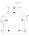
図1,2に示す実施例1は、木造家屋における厚み巾150mmの下部材である基礎Kと,120mm×120mmの横部材である木土台Mと,105mm×105mmの木材の上部材である1階柱C1との交点部位X1に設けた補強構造例である。補強板S1は厚み9mmの亜鉛メッキ鋼板であり、1階柱C1の上方に2個の直径22mmで長さ206mmのステンレスボルト製のアンカーボルトB1,B2を120mmの上下間隔離して植設し、1階柱C1の下方の右位置の横部材である木土台Mに直径22mmで長さ206mmのステンレスボルト製のアンカーボルトB3を1個植設している。その植設位置は1階柱C1の縦中心線からの右オフセット長さは228mmである。更に、同アンカーボルトB3の下方の同じオフセット長さの右位置の下部材である基礎Kの位置で上方のアンカーボルトB2の下方680mmの位置に下方のアンカーボルトB4を植設している。前記アンカーボルトB1,B2,B3,B4は各部材との螺合部の接着剤注入個所PSにHILTI社販売の樹脂製の接着系注入方式アンカー「HIT−RE 500 V3」を注入したもので、PSはその接着剤注入個所である。
そして、上下のアンカーボルトB1とB4,B2とB4との上下間隔は800mmと680mmであり、アンカーボルトB1,B2とアンカーボルトB3,B4の左右の間隔は228mmの長さで、BNはアンカーボルトB1〜B4に螺合して補強板S1を取付けるナット、DBは胴縁、SDはサイディング、SEはシーリング、MBは木土台Mと基礎Kとを連結する上下方向に延びたアンカーボルト、Wはワッシャーである。
このように、アンカーボルトB1〜B4は交点部位の1階柱C1と木土台Mと基礎Kの三部材に分かれて植設され、上記接着剤により4本のアンカーボルトB1〜B4の引き抜き安全荷重値として40KNを確保した。上下の間隔も680mm,800mm及び左右の間隔も280mmあり、三部材を高い強度の亜鉛メッキされた厚み9mmの補強板S1で計4本のアンカーボルトB1〜B4で連結され、又上下間隔・左右間隔も充分の長さをもつことで、この交点部位X1の横荷重及びモーメントに対し、強い強度で連結し、この部位の連結強度を高め、耐震性を高くできた。
(Example 1)
Example 1 shown in FIGS. 1 and 2 is a foundation K which is a lower member having a width of 150 mm in a wooden house, a wooden base M which is a horizontal member having a size of 120 mm × 120 mm, and an upper member having a width of 105 mm × 105 mm. a reinforcing structure example in which the intersection portion X 1 and Kaibashira C 1. The reinforcing plate S 1 is a 9 mm-thick galvanized steel plate, and two stainless steel anchor bolts B 1 and B 2 each having a diameter of 22 mm and a length of 206 mm are vertically separated from each other by 120 mm above the first floor column C 1. implanted, and a 1 Kaibashira C 1 of the anchor bolt B 3 stainless bolt length 206mm diameter 22mm wood foundation M is a transverse member of the right position of the downwardly one implanted. Its planted position right offset length from the longitudinal center line of 1 Kaibashira C 1 is 228 mm. Further, by implanting the lower anchor bolts B 4 in position above the lower 680mm anchor bolt B 2 at the position of the basal K is a lower member of the right position of the same offset length below the same anchor bolt B 3 I have. For the anchor bolts B 1 , B 2 , B 3 , B 4 , resin-based adhesive injection type anchor “HIT-RE 500 V3” sold by HILTI is injected into the adhesive injection point PS of the screwed portion with each member. Where PS is the adhesive injection point.
The vertical distance between the upper and lower anchor bolts B 1 and B 4 , B 2 and B 4 is 800 mm and 680 mm, and the horizontal distance between the anchor bolts B 1 and B 2 and the anchor bolts B 3 and B 4 is 228 mm. In the length, BN is a nut to be screwed to the anchor bolts B 1 to B 4 to mount the reinforcing plate S 1 , DB is the rim, SD is the siding, SE is the sealing, and MB is the wooden base M and the base K is connected. An anchor bolt W extending in the vertical direction is a washer.
Thus, the anchor bolt B 1 .about.B 4 is implanted divided into three
(実施例2)
図3,4に示す実施例2の交点部位の構成は、下部材である1階柱C1と左右部材である2階桁L2と105mm×105mmの上部材である2階柱C2との三部材の交点部位X2を連結するもので、2階柱C2の上方に2本のアンカーボルトB5,B6を、又下方の1階柱C1に2本のアンカーボルトB7,B8を設けている。又、2階桁L2の左右に各1本のアンカーボルトB9,B10を植設している。そして、十字状の9mm厚みの亜鉛メッキ鋼板の補強板S2が使用されている。これらアンカーボルトB5〜B10の各部材の植設は実施例1同様に、HILTI社販売の樹脂製の接着系注入方式アンカー「HIT−RE 500 V3」を螺合面である接着剤注入個所PSに注入し、6本のアンカーボルトB5〜B10の引き抜き安全荷重値として30KNを確保している。
この実施例2での1階柱C1と2階柱C2との上方のアンカーボルトB5,B6と下方のアンカーボルトB7,B8との間隔は最大800mm,最小560mmであり、左右のアンカーボルトB9,B10は左右間隔は385mm程であり、充分に長い間隔を保持している。よって、左右の横荷重・上下及び左右に対する曲げモーメントに対し、各アンカーボルトB5〜B10は高い引き抜き安全荷重値として30KNを保持していることと併せて、高い曲げモーメント外部荷重に対し充分に耐える強度を保有できるものとなっている。
(Example 2)
Configuration of intersection portions of the second embodiment shown in FIGS. 3 and 4, a
In the second embodiment, the distance between the upper anchor bolts B 5 and B 6 of the first and second columns C 1 and C 2 and the lower anchor bolts B 7 and B 8 is 800 mm at the maximum and 560 mm at the minimum. The distance between the left and right anchor bolts B 9 and B 10 is about 385 mm, which is a sufficiently long distance. Therefore, with respect to the lateral load on the left and right, the bending moment on the up and down, and the left and right, each of the anchor bolts B 5 to B 10 holds 30 KN as a high pull-out safe load value, and is sufficient for a high bending moment external load. It can retain the strength to withstand.
本考案の他の交点部位X3〜X8とその補強板S3〜S9の外形状とアンカーボルトの配置を図5〜8に示している。いずれも三部材の躯体として基礎K,木土台Mと1階柱C1,2階柱C2と2階桁L2あるいは小屋桁材L3,柱材C3の三部材の交点部位X5,X6,X7,X8における補強構造例で、同じ樹脂製の接着剤を植設の螺合部の接着剤注入個所PSに注入していて、且つ亜鉛メッキ製のステンレスの肉厚の補強板S5,S6,S7,S8を使用している。いずれも引き抜き安全荷重として30KN以上とし、アンカーボルトの本数を6本以上としている。
この他の例でも実施例1,2同様の強度補強による耐震性の向上が期待できるものである。
Other intersection portion X 3 to X 8 of the present invention and the arrangement of the outer shape and the anchor bolt of the reinforcing plate S 3 to S 9 are shown in Figures 5-8. Both basal K as precursor of the three members, wood base M and 1
In this other example, improvement in earthquake resistance can be expected by the same strength reinforcement as in the first and second embodiments.
図10は、従来の木造家屋での柱と木土台との間でのホゾHとホゾ穴HHによる連結状態を示す。これに筋かいSUJが柱Cに取付の連結具SUJKで取付けられることで筋かいSUJからの横荷重でこのホゾHとホゾ穴HHの連結が破壊されるものであるが、本考案の交点部位の三部材に対してアンカーボルトと補強板の連結と接着剤注入によって、強い横荷重に対する高い引き抜き安全荷重を可能とし、そのホゾ部の破壊を抑えることができる。 FIG. 10 shows a state in which a tenon H and a tenon hole HH are connected between a pillar and a wooden base in a conventional wooden house. The connection between the mortise H and the mortise HH is broken by the lateral load from the reinforcement SUJ when the bracing SUJ is attached to the column C with the connecting tool SUJK. By connecting the anchor bolt and the reinforcing plate and injecting the adhesive to the three members, a high pull-out safe load against a strong lateral load can be achieved, and breakage of the tenon portion can be suppressed.
本考案の上下のアンカーボルトとの間の取付間隔は300mm以上及び左右のアンカーボルトとの間の取付間隔は180mm以上であれば、しかもアンカーボルトの引き抜き安全荷重値30KN以上又はもっと高い40KN以上であれば、この部位に働く地震での曲げモーメントに対して耐えることができる構造強度が可能と判断される。 The mounting interval between the upper and lower anchor bolts of the present invention is 300 mm or more, and the mounting interval between the left and right anchor bolts is 180 mm or more, and the pull-out safety load value of the anchor bolt is 30 KN or more or 40 KN or more. If there is, it is judged that the structural strength capable of withstanding the bending moment due to the earthquake acting on this portion is possible.
本考案は家屋以外の木材を使用した建築物に対しても利用できる。 The present invention can also be used for buildings using wood other than houses.
K 基礎
M 木土台
C 柱
C1 1階柱
C2 2階柱
C3 柱材
DB 胴縁
B1〜B10,B31〜B66 アンカーボルト
BN ナット
L2 2階桁
L3 小屋桁材
PS 接着剤注入個所
MB アンカーボルト
S1〜S9 補強板
S10〜S90 ボルト孔
SD サイディング
SE シーリング
X1〜X8 交点部位
H ホゾ
HH ホゾ穴
SUJ 筋かい
SUJK 連結具
W ワッシャー
K Basic M wood foundation
Claims (4)
上下左右に配置されることとなる三部材それぞれに、同一水平方向に突出するように複数本のアンカーボルトを所定の上下又は左右間隔長さより長い間隔を保持するように植設させ、
しかも同アンカーボルトは植設された部材に樹脂接着剤をもって強固に固着させて、アンカーボルトを強く引張してこれを植設した部材から引き抜くこととなる引き抜きの引張力の数値より余裕をもって低い数値に設定した引き抜きに対する指標となる引き抜き安全荷重値を高く確保し、更に前記アンカーボルトを植設させた三部材に対面するように高強度の補強板を配置するとともに、同補強板に前記アンカーボルトを貫通させ、アンカーボルトと前記補強板とをナットで強固に連結させ、木造家屋の躯体の交点部位を補強板とアンカーボルトで強度補強することで家屋の耐震性を高めた、木造建築物の耐震強度の補強構造。 At the intersection of the skeleton where three or more members of the upper pillar, lower pillar, girder, beam, wooden base or foundation that will be the skeleton of the wooden house will be arranged vertically and horizontally
For each of the three members to be arranged vertically and horizontally, a plurality of anchor bolts are implanted so as to protrude in the same horizontal direction so as to maintain an interval longer than a predetermined vertical or horizontal interval length,
Moreover, the anchor bolt is firmly fixed to the planted member with a resin adhesive, and the anchor bolt is strongly pulled to pull it out from the planted member. A high withdrawal safety load value serving as an indicator for pullout set in the above is secured, and a high-strength reinforcing plate is arranged so as to face the three members on which the anchor bolts are implanted, and the anchor bolt is mounted on the reinforcing plate. Through, the anchor bolts and the reinforcing plate are firmly connected with nuts, and the intersection of the frame of the wooden house is reinforced with the reinforcing plate and anchor bolts to enhance the seismic resistance of the house. Reinforced structure with earthquake resistance.
前記交点部位に前記補強板と前記アンカーボルトをナット連結させることで耐震強度を高めるとともに、筋かいの横荷重に対する交点部位のホゾとホゾ穴の連結強度を高めてホゾ構造の破壊を少なくした、請求項1〜3いずれか記載の木造建築物の耐震強度の補強構造。 The wooden members at the intersection of the wooden house are connected by a tenon and a mortise, and the end of the brace is further connected to a pillar at the intersection by end fittings,
While increasing the seismic strength by connecting the reinforcing plate and the anchor bolt to the intersection at the nut, the joint strength of the mortise and the mortise at the intersection with respect to the lateral load of the brace was increased to reduce the destruction of the mortise structure. The reinforcing structure for seismic strength of a wooden building according to claim 1.
Priority Applications (1)
| Application Number | Priority Date | Filing Date | Title |
|---|---|---|---|
| JP2019004773U JP3225322U (en) | 2019-12-16 | 2019-12-16 | Reinforcement structure for seismic strength of wooden buildings |
Applications Claiming Priority (1)
| Application Number | Priority Date | Filing Date | Title |
|---|---|---|---|
| JP2019004773U JP3225322U (en) | 2019-12-16 | 2019-12-16 | Reinforcement structure for seismic strength of wooden buildings |
Publications (1)
| Publication Number | Publication Date |
|---|---|
| JP3225322U true JP3225322U (en) | 2020-02-27 |
Family
ID=69593864
Family Applications (1)
| Application Number | Title | Priority Date | Filing Date |
|---|---|---|---|
| JP2019004773U Expired - Fee Related JP3225322U (en) | 2019-12-16 | 2019-12-16 | Reinforcement structure for seismic strength of wooden buildings |
Country Status (1)
| Country | Link |
|---|---|
| JP (1) | JP3225322U (en) |
Cited By (1)
| Publication number | Priority date | Publication date | Assignee | Title |
|---|---|---|---|---|
| JP7054857B1 (en) | 2021-11-12 | 2022-04-15 | 早苗男 藤崎 | Reinforcement structure of wooden building and reinforcement method of wooden building |
-
2019
- 2019-12-16 JP JP2019004773U patent/JP3225322U/en not_active Expired - Fee Related
Cited By (2)
| Publication number | Priority date | Publication date | Assignee | Title |
|---|---|---|---|---|
| JP7054857B1 (en) | 2021-11-12 | 2022-04-15 | 早苗男 藤崎 | Reinforcement structure of wooden building and reinforcement method of wooden building |
| JP2023072168A (en) * | 2021-11-12 | 2023-05-24 | 早苗男 藤崎 | Reinforcement structure of wooden building and reinforcement method of wooden building |
Similar Documents
| Publication | Publication Date | Title |
|---|---|---|
| KR101657481B1 (en) | Seismic reinforcement structure and retrofitting method of infilled masonry wall with hollow steel plate | |
| CN201339313Y (en) | Scaffold wall connecting piece | |
| JP3041271B2 (en) | Wooden joining method | |
| CN212376021U (en) | Steel corbel and support-free installation connecting node comprising same | |
| JP4585595B2 (en) | Seismic reinforcement structure for wooden houses and seismic reinforcement method for wooden houses | |
| CN220225693U (en) | Vestibule structure with hidden bracket | |
| CN108086535B (en) | An Assembled Square Steel Tube Steel Plate Concrete Composite Shear Wall | |
| CN204001650U (en) | Overhanging scaffold for building | |
| CN203347205U (en) | Overhung scaffold | |
| CN210976063U (en) | Combined type continuous collapse prevention steel frame | |
| JP4672459B2 (en) | Building reinforcement method | |
| CN208981514U (en) | Modular more high-rise assembling type steel structures are engaged steel girder frame central supported system | |
| CN217679705U (en) | Post-anchored steel support for post-anchored net rack | |
| JP4907454B2 (en) | Wall frame reinforcement hardware | |
| CN117449643A (en) | Connecting node reinforcing structure for frame structure construction | |
| KR102578034B1 (en) | Assembly construction method of noncombustible engineering plastic panel attached FRP wraping and X-brace for seismic reinforcement of column | |
| CN211524174U (en) | Novel basement antidetonation reinforcing building structure | |
| JP2013087543A (en) | Reinforcing structure for woody house, and woody house | |
| CN209025205U (en) | Assembly concrete frame structure system | |
| CN222575779U (en) | Prefabricated concrete components | |
| JP5358203B2 (en) | Building unit fixed structure and unit building | |
| JP3167210U (en) | Anti-earthquake reinforcement hardware | |
| KR100705560B1 (en) | Bonded Structure of Concrete Filled Steel Tube Column and Reinforced Concrete Flat Plate Reinforced by Compression Stand by High Strength Concrete | |
| TWI810500B (en) | The fixed structure between the wall and the pillar | |
| CN220978103U (en) | Retaining wall structure of anchor cable lattice beam stress system |
Legal Events
| Date | Code | Title | Description |
|---|---|---|---|
| R150 | Certificate of patent or registration of utility model |
Ref document number: 3225322 Country of ref document: JP Free format text: JAPANESE INTERMEDIATE CODE: R150 |
|
| LAPS | Cancellation because of no payment of annual fees |