JP3200348U - Portable sitting chair - Google Patents
Portable sitting chair Download PDFInfo
- Publication number
- JP3200348U JP3200348U JP2015003816U JP2015003816U JP3200348U JP 3200348 U JP3200348 U JP 3200348U JP 2015003816 U JP2015003816 U JP 2015003816U JP 2015003816 U JP2015003816 U JP 2015003816U JP 3200348 U JP3200348 U JP 3200348U
- Authority
- JP
- Japan
- Prior art keywords
- adjustment plate
- lower adjustment
- position opposite
- base point
- leg
- Prior art date
- Legal status (The legal status is an assumption and is not a legal conclusion. Google has not performed a legal analysis and makes no representation as to the accuracy of the status listed.)
- Expired - Fee Related
Links
Images

Landscapes
- Special Chairs (AREA)
Abstract
【課題】 本考案は、老人や脚部に障害を有する者にあっては正座することが困難であるため、補助椅子を使わねばならない場合があるところ、複数段に分かれて折り畳みし得るような正座用の補助椅子を提供することを目的とする。【解決手段】 基板1,1上に設置する下調節板2の一端部に下基点部3を設けるとともにこの下基点部の反対位置の下調節板の他端部に適当間隔をおいて複数の下掛止部4,4を設け、正面?状に枢着6,6した前後側2本の折畳み脚材5,5の一方部は前記下調節板の下基点部に係合し、この折畳み脚材の他方部は前記下調節板の下掛止部の一つに掛止めるようにし、前記2本の折畳み脚材の他方部は座部材下に設置する上調節板8の一端部に上基点部9を設けるとともにこの上基点部の反対位置の下調節板の他端部に適当間隔をおいて複数の上掛止部10,10を設けて成るものである。【選択図】 図2PROBLEM TO BE SOLVED: Since the present invention is difficult for an elderly person or a person with a disability in a leg, it may be necessary to use an auxiliary chair. An object is to provide an auxiliary chair for sitting. A lower base plate portion 3 is provided at one end portion of a lower adjustment plate 2 installed on a substrate 1, 1 and a plurality of gaps are provided at an appropriate interval at the other end portion of the lower adjustment plate at a position opposite to the lower base plate portion. One of the two front and rear folding legs 5 and 5 provided with lower latching portions 4 and 4 and pivoted in a frontal shape 6 and 6 engages with the lower base portion of the lower adjustment plate. The other part of the leg is hooked on one of the lower hooks of the lower adjustment plate, and the other part of the two folding legs is placed on one end of the upper adjustment plate 8 installed under the seat member. A base point portion 9 is provided, and a plurality of upper hooking portions 10, 10 are provided at an appropriate interval at the other end portion of the lower adjustment plate at a position opposite to the upper base point portion. [Selection] Figure 2
Description
本考案は、携帯用の正座椅子に関するものである。 The present invention relates to a portable seat chair.
老人や脚部に障害を有する者にあっては正座することが困難であるため、補助椅子を使わねばならない場合があるところ、従来、公知文献としては、次のようなものが知られており、これには高さ12cmの脚部が折り畳まれて高さ6cm程度になるという説明があるものである。 Since it is difficult for the elderly and those with leg disabilities to sit upright, there are cases where an auxiliary chair must be used. In this, there is an explanation that a leg portion having a height of 12 cm is folded to a height of about 6 cm.
しかしながら、この公知文献に係る補助椅子は×状に成る脚部が単純に折り畳まれるだけのもので、複数段に分かれて折り畳みし得るような正座用の補助椅子ではないことに鑑み、本考案はこれを改良した補助椅子を提供することを目的とするものである。 However, in view of the fact that the auxiliary chair according to this publicly known document is simply a foldable leg portion that is X-shaped, and is not an auxiliary chair for a regular seat that can be folded in multiple stages, the present invention is An object of the present invention is to provide an auxiliary chair improved from this.
本考案は、基板上に設置する下調節板の一端部に下基点部を設けるとともにこの下基点部の反対位置の下調節板の他端部に適当間隔をおいて複数の下掛止部を設け、正面×状に枢着した前後側2本の折畳み脚材の一方部は前記下調節板の下基点部に係合し、この折畳み脚材の他方部は前記下調節板の下掛止部の一つに掛止めるようにし、前記2本の折畳み脚材の他方部は座部材下に設置する上調節板の一端部に上基点部を設けるとともにこの上基点部の反対位置の下調節板の他端部に適当間隔をおいて複数の上掛止部を設けて成るものである。 In the present invention, a lower base point is provided at one end of the lower adjustment plate installed on the substrate, and a plurality of lower stoppers are provided at an appropriate interval at the other end of the lower adjustment plate at a position opposite to the lower base point. Provided, one part of the front and rear folding legs pivoted in a front X shape is engaged with the lower base part of the lower adjustment plate, and the other part of the folding leg is under-hanging the lower adjustment plate The other part of the two folding legs is provided with an upper reference point at one end of the upper adjustment plate installed under the seat member and the lower adjustment of the position opposite to the upper reference point. A plurality of upper hooking portions are provided at appropriate intervals on the other end of the plate.
本考案にあっては、一回定型の高度調整だけではなく、使用者の正座時の希望に合わせた高さ調節を複数段に分けて行うことができるものであり、また長方形の座部材椅子の使用方向は横向きでも縦向きでもよい。 In the present invention, not only a single fixed height adjustment but also a height adjustment according to the user's desired seating can be performed in multiple stages, and a rectangular seat member chair The direction of use may be horizontal or vertical.
しかも、比較的小型であるから、携帯用の正座椅子となり、常に安定性良く使用することができるのである。 And since it is comparatively small, it becomes a portable seat chair and can always be used with good stability.
本考案の正座椅子を使用する場所は、一般的には畳敷の和室であるが、使用者はあくまでも正座時の両脚を曲げた時に、その間にはさんで腰掛けた座椅子として使用するものである。 The place where the seated chair of the present invention is used is generally a Japanese-style room with a tatami mat, but when a user bends both legs in the sitting position, the seat is used as a sitting chair between them. It is.
即ち、上方の座部材と下方の基板との間の前後側に介装する×状の折畳み脚材の位置を、それぞれ上下任意の掛止部に係合すれば、そのまま定位置として固定される。 That is, if the positions of the X-shaped folding legs interposed on the front and rear sides between the upper seat member and the lower substrate are respectively engaged with the upper and lower arbitrary latching portions, they are fixed in place as they are. .
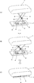
また、不使用時には、折畳み脚材の上下の掛止状態を各掛止部から離脱して、その基点部を支点に偏平状態に折り畳みすればよい。(この作用形態の動きについては、図1(A)(B)(C)の矢印を参照されたい。) Further, when not in use, the upper and lower hooking states of the folding legs may be detached from the respective hooking portions and folded into a flat state with the base point as a fulcrum. (Refer to the arrows in FIGS. 1A, 1B and 1C for the movement of this mode of action.)
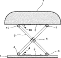
1は適当長さの縦巾と横巾から成る基板で、この基板上には下調節板2を設置する。
3は前記下調節板2での一端部に設ける下基点部で、この下基点部から反対位置の下調節板の他端部には、適当間隔をおいて複数の下掛止部4,4を設ける。この下掛止部4は2個以上の複数とする。
5,5は上端部に座部材7を設置した正面×状に枢着6,6して成る前後側2本の折畳み脚材で、この脚材の一方部は前記下調節板2の下基点部3に係合して支点となり、この脚材の他方部は下調節板2の下掛止部4,4の一つに掛け止めるようにする。
8は前記座部材7の底面部に設置する上調節板で、この上調節板の一端部には上基点部9を設け、この上基点部から反対位置の上調節板8の他端部には適当間隔をおいて複数の上掛止部10,10を設ける。この上掛止部10は2個以上の複数とする。
8 is an upper adjustment plate installed on the bottom surface of the
1,1 基板
2 下調節板
3 下基点部
4,4 下掛止部
5,5 折畳み脚材
6,6 枢着
7 座部材
8 上調節板
9 上基点部
10,10 上掛止部
DESCRIPTION OF
Claims (1)
Priority Applications (1)
| Application Number | Priority Date | Filing Date | Title |
|---|---|---|---|
| JP2015003816U JP3200348U (en) | 2015-07-29 | 2015-07-29 | Portable sitting chair |
Applications Claiming Priority (1)
| Application Number | Priority Date | Filing Date | Title |
|---|---|---|---|
| JP2015003816U JP3200348U (en) | 2015-07-29 | 2015-07-29 | Portable sitting chair |
Publications (1)
| Publication Number | Publication Date |
|---|---|
| JP3200348U true JP3200348U (en) | 2015-10-15 |
Family
ID=54330329
Family Applications (1)
| Application Number | Title | Priority Date | Filing Date |
|---|---|---|---|
| JP2015003816U Expired - Fee Related JP3200348U (en) | 2015-07-29 | 2015-07-29 | Portable sitting chair |
Country Status (1)
| Country | Link |
|---|---|
| JP (1) | JP3200348U (en) |
Cited By (1)
| Publication number | Priority date | Publication date | Assignee | Title |
|---|---|---|---|---|
| CN108338567A (en) * | 2018-04-10 | 2018-07-31 | 振立(漳州)工贸有限公司 | A kind of adjustable multifunctional folding chair of outdoor |
-
2015
- 2015-07-29 JP JP2015003816U patent/JP3200348U/en not_active Expired - Fee Related
Cited By (1)
| Publication number | Priority date | Publication date | Assignee | Title |
|---|---|---|---|---|
| CN108338567A (en) * | 2018-04-10 | 2018-07-31 | 振立(漳州)工贸有限公司 | A kind of adjustable multifunctional folding chair of outdoor |
Similar Documents
| Publication | Publication Date | Title |
|---|---|---|
| US10292503B2 (en) | Portable adjustable chair | |
| JP3185219U (en) | Folding rocking chair | |
| JP2013533072A (en) | Seat furniture items | |
| CN102440573B (en) | multifunctional chair | |
| KR200459159Y1 (en) | A Separation and compound type bed combined with a sofa set | |
| JP3194283U (en) | Swivel chair | |
| JP3193443U (en) | Portable toilet | |
| JP2018042910A (en) | Chair and table | |
| KR101560494B1 (en) | Bend prevention device for seat of folding type chair | |
| KR20160105701A (en) | Folding backrest and armrest is marked with a chair. | |
| KR101454800B1 (en) | Table with chair | |
| KR200431273Y1 (en) | Easy to deform shape couch system | |
| JP3679098B2 (en) | Furniture set | |
| KR200454310Y1 (en) | Bedside chair | |
| KR20170032791A (en) | Lawn chair | |
| CN205379087U (en) | Chair | |
| JP3198629U (en) | Carpet with some seats | |
| JP3192579U (en) | stool | |
| JP2008506438A (en) | Chair | |
| JP2016067584A (en) | Chair | |
| CN206380999U (en) | Children's chair plate | |
| JP3199374U (en) | Chair with armrests | |
| JP2017185087A (en) | Dining table with bench | |
| KR200394668Y1 (en) | Chair assembly | |
| TWM557063U (en) | Sofa armrest structure with footrest cushion |
Legal Events
| Date | Code | Title | Description |
|---|---|---|---|
| R150 | Certificate of patent or registration of utility model |
Ref document number: 3200348 Country of ref document: JP Free format text: JAPANESE INTERMEDIATE CODE: R150 |
|
| LAPS | Cancellation because of no payment of annual fees |