JP3187004U - Vehicle controlled by the driver - Google Patents
Vehicle controlled by the driver Download PDFInfo
- Publication number
- JP3187004U JP3187004U JP2013002616U JP2013002616U JP3187004U JP 3187004 U JP3187004 U JP 3187004U JP 2013002616 U JP2013002616 U JP 2013002616U JP 2013002616 U JP2013002616 U JP 2013002616U JP 3187004 U JP3187004 U JP 3187004U
- Authority
- JP
- Japan
- Prior art keywords
- chassis
- vehicle
- driver
- force
- vehicle according
- Prior art date
- Legal status (The legal status is an assumption and is not a legal conclusion. Google has not performed a legal analysis and makes no representation as to the accuracy of the status listed.)
- Expired - Fee Related
Links
Images


Classifications
-
- B—PERFORMING OPERATIONS; TRANSPORTING
- B62—LAND VEHICLES FOR TRAVELLING OTHERWISE THAN ON RAILS
- B62D—MOTOR VEHICLES; TRAILERS
- B62D1/00—Steering controls, i.e. means for initiating a change of direction of the vehicle
- B62D1/02—Steering controls, i.e. means for initiating a change of direction of the vehicle vehicle-mounted
-
- B—PERFORMING OPERATIONS; TRANSPORTING
- B62—LAND VEHICLES FOR TRAVELLING OTHERWISE THAN ON RAILS
- B62D—MOTOR VEHICLES; TRAILERS
- B62D9/00—Steering deflectable wheels not otherwise provided for
- B62D9/02—Steering deflectable wheels not otherwise provided for combined with means for inwardly inclining vehicle body on bends
-
- B—PERFORMING OPERATIONS; TRANSPORTING
- B62—LAND VEHICLES FOR TRAVELLING OTHERWISE THAN ON RAILS
- B62K—CYCLES; CYCLE FRAMES; CYCLE STEERING DEVICES; RIDER-OPERATED TERMINAL CONTROLS SPECIALLY ADAPTED FOR CYCLES; CYCLE AXLE SUSPENSIONS; CYCLE SIDE-CARS, FORECARS, OR THE LIKE
- B62K5/00—Cycles with handlebars, equipped with three or more main road wheels
- B62K5/10—Cycles with handlebars, equipped with three or more main road wheels with means for inwardly inclining the vehicle body on bends
-
- B—PERFORMING OPERATIONS; TRANSPORTING
- B60—VEHICLES IN GENERAL
- B60G—VEHICLE SUSPENSION ARRANGEMENTS
- B60G2300/00—Indexing codes relating to the type of vehicle
- B60G2300/45—Rolling frame vehicles
Abstract
【課題】運転者への実感覚のフィードバックと優れた均衡とを得ることができる運転者によって制御される車両を提供する。
【解決手段】(a)道路によって支持される第1のシャーシ2と、(b)運転者6を支持すると共に第1のシャーシ2に可動結合するように構成され、道路とは機械的に接触しない第2のシャーシ5と、(c)車両の動きを制御するように構成された少なくとも1つの機構とを備えている。上述の機構が、第2のシャーシ5内に設けられかつステアリングユニットに連結されており、同一の方向にステアリングされた際に、動いているバイクの前輪に作用する力の方向を復元させるジャイロを備えている。
【選択図】図1Provided is a vehicle controlled by a driver, which can obtain a real feedback to the driver and an excellent balance.
(A) a first chassis 2 supported by a road; and (b) configured to support a driver 6 and to be movably coupled to the first chassis 2 in mechanical contact with the road. A second chassis 5 that does not, and (c) at least one mechanism configured to control the movement of the vehicle. The above-described mechanism is provided in the second chassis 5 and connected to the steering unit. When the steering is steered in the same direction, a gyro that restores the direction of the force acting on the front wheels of the moving motorcycle is provided. I have.
[Selection] Figure 1
Description
本考案は、概して、運転者によって制御される車両に関し、より特定的には、車両に対する運転者の身体の瞬間的な位置に応じて、車両の部分間の相対的な位置に応じて、並びに、車両、運転者及びそれらの任意の部分に印加される力に応じて制御される車両に関する。 The present invention relates generally to a vehicle controlled by a driver, and more particularly, depending on the instantaneous position of the driver's body relative to the vehicle, depending on the relative position between parts of the vehicle, and The present invention relates to a vehicle that is controlled according to the force applied to the vehicle, the driver, and any part thereof.
自動車産業における電子制御方式による運転(DbW)技術は、従来の機械及び油圧制御システムを、電子機械アクチュエータ並びにペダル及びステアリングホイール・エミュレータのごとき人間機械インタフェースを用いた電子制御システムに置換する。従って、ステアリングコラム、中間シャフト、ポンプ、ホース、液体、ベルト、冷却器、ブレーキブースタ及びマスターシリンダのごとき従来の構成要素は、車両から除去される。 Electronically controlled driving (DbW) technology in the automotive industry replaces traditional mechanical and hydraulic control systems with electronic control systems using electromechanical actuators and human machine interfaces such as pedals and steering wheel emulators. Thus, conventional components such as steering columns, intermediate shafts, pumps, hoses, liquids, belts, coolers, brake boosters and master cylinders are removed from the vehicle.
DbW技術は、ステアリングコラムに関連した衝突損傷の危険度を減少させると共に、キャビンの再設計から技術者を解放させるものとして認識されてきた。DbW技術は、さらに、ステアリング・ヒューマン・インタフェースが、例外的な形状及び配達方法を呈することを可能にする。さらにまた、ほとんどの場合、現在のDbWシステムは、従来の陸上及び航空車両で良く知られている従来の手動制御のステアリングインタフェースを保有する。 DbW technology has been recognized as reducing the risk of collision damage associated with the steering column and freeing the engineer from cabin redesign. DbW technology also allows the steering human interface to exhibit exceptional shapes and delivery methods. Furthermore, in most cases, current DbW systems possess conventional manually controlled steering interfaces that are well known in conventional land and air vehicles.
手動によるヒューマン・インタフェース、特にDbWのヒューマン・インタフェースは、直感的な使い易さを提供するが、車両の均衡を維持することが難しく、かつ充分なステアリングフィードバックを提供しないことで知られている。さらに、これが提供する運転感覚(driving experience)は、運転感覚の向上を損ねるであろう主に着席した静止状態のものである。 Manual human interfaces, particularly DbW human interfaces, are known to provide intuitive ease of use, but difficult to maintain vehicle balance and do not provide sufficient steering feedback. Furthermore, the driving experience it provides is primarily seated and stationary, which will impair the improvement of driving sensation.
従って、運転者への実感覚のフィードバックと優れた均衡とを得ることができるDbWステアリングシステム用のヒューマン・インタフェースを提供することが長年に渡って切望されていた。さらに、この種のインタフェースは、完全かつ挑戦的な運転感覚を求める要望に回答するものである。 Accordingly, it has long been desired to provide a human interface for a DbW steering system that can provide real feedback to the driver and excellent balance. In addition, this type of interface answers the need for a complete and challenging driving sensation.
本考案によれば、(a)道路によって支持される第1のシャーシと、(b)運転者を支持すると共に第1のシャーシに可動結合するように構成され、道路とは機械的に接触しない第2のシャーシと、(c)車両の動きを制御するように構成された少なくとも1つの機構とを備え、運転者によって制御される車両が提供される。 According to the present invention, (a) a first chassis supported by a road and (b) a driver is supported and is movably coupled to the first chassis, and does not mechanically contact the road. A vehicle is provided that includes a second chassis and (c) at least one mechanism configured to control movement of the vehicle and is controlled by a driver.
本考案の1つの主たる特徴は、第2のシャーシに印加されかつ第1のシャーシ及び第2のシャーシ間の結合点を向く力の合成ベクトルを運転者が維持可能であり、これにより、第2のシャーシ及び運転者の質量中心の直線的変位の水平成分が求心力、加速力又は減速力の水平成分と同一の方向を向くように、上述の機構が、第2のシャーシ及び運転者の身体の変化位置に非弾性的に反応するように構成されていることにある。 One main feature of the present invention is that the driver can maintain a composite vector of forces applied to the second chassis and pointing to the connection point between the first chassis and the second chassis, thereby So that the horizontal component of the linear displacement of the chassis and the center of mass of the driver is oriented in the same direction as the horizontal component of the centripetal force, acceleration force or deceleration force. It exists in being comprised so that it may react inelastically to a change position.
本考案の他の主たる特徴は、上述の機構が、第2のシャーシに印加されかつ第1のシャーシ及び第2のシャーシ間の結合点を向く力の合成ベクトルを運転者が維持可能であり、これにより、第2のシャーシ及び運転者の質量中心の直線的変位の水平成分が求心力、加速力又は減速力の水平成分と同一の方向を向くように構成されていることにある。 Another main feature of the present invention is that the above-described mechanism allows the driver to maintain a combined vector of forces applied to the second chassis and facing the connection point between the first chassis and the second chassis, Accordingly, the horizontal component of the linear displacement of the second chassis and the center of mass of the driver is configured to face the same direction as the horizontal component of the centripetal force, acceleration force, or deceleration force.
第2のシャーシが、運転者と置換可能であることが好ましい。 Preferably, the second chassis is replaceable with the driver.
車両の動きが、第2のシャーシの位置に従って制御されることも好ましい。 It is also preferred that the movement of the vehicle is controlled according to the position of the second chassis.
不安定な車両の動き及び実時間の道路条件における車両グリップの損失を認識するように構成された検知手段を備えたことも好ましい。 It is also preferred to have sensing means configured to recognize unstable vehicle movement and vehicle grip loss in real-time road conditions.
制御機構が、ステアリング・ユニットをさらに備えており、車両が第1のシャーシに対する第2のシャーシの角度及び直線的変位とは別個にステアリングを手動制御するように構成されていることも好ましい。 It is also preferred that the control mechanism further comprises a steering unit and the vehicle is configured to manually control the steering separately from the angle and linear displacement of the second chassis relative to the first chassis.
瞬間的な位置の変化が、第1のシャーシに対する第2のシャーシ及び第2のシャーシに対する運転者の身体の角度及び直線的変位によって特徴付けられることも好ましい。 It is also preferred that the instantaneous position change is characterized by an angle and a linear displacement of the driver's body relative to the second chassis and the second chassis relative to the first chassis.
第2のシャーシが、第1のシャーシに対するこの第2のシャーシの傾きにより、長手方向及び横方向の道路勾配を補償するように構成されていることも好ましい。 It is also preferred that the second chassis is configured to compensate for longitudinal and lateral road gradients due to the inclination of the second chassis relative to the first chassis.
第2のシャーシが、この第2のシャーシを所定位置の安定させるように構成されている安定化手段をさらに備えていることも好ましい。 It is also preferred that the second chassis further comprises stabilization means configured to stabilize the second chassis in place.
第2のシャーシに印加される力の均衡が、運転方向、速度、加速及び減速を変化させること、第1のシャーシに対して第2のシャーシの傾けること、第2のシャーシの安定化位置を調整すること、並びにこれらの任意の組合せからなる群から選択される車両特性を制御することによってなされるように構成されていることも好ましい。 The balance of forces applied to the second chassis changes the driving direction, speed, acceleration and deceleration, tilts the second chassis relative to the first chassis, and stabilizes the second chassis. It is also preferably configured to be adjusted and to control vehicle characteristics selected from the group consisting of any combination thereof.
第2のシャーシに印加される力の均衡が、運転方向、速度、加速及び減速を変化させること、第1のシャーシに対して第2のシャーシの傾けること、第2のシャーシの安定化位置を調整すること、並びにこれらの任意の組合せからなる群から選択される車両特性を制御することによってなされるように機構を制御するべくあらかじめプログラムされたコンピュータ手段をさらに備えていることも好ましい。 The balance of forces applied to the second chassis changes the driving direction, speed, acceleration and deceleration, tilts the second chassis relative to the first chassis, and stabilizes the second chassis. It is also preferred to further comprise computer means preprogrammed to adjust and to control the mechanism to be done by controlling vehicle characteristics selected from the group consisting of any combination thereof.
コンピュータ手段が、第2のシャーシのその縦軸に関する角度回転及び第1のシャーシに対する横方向の直線的変化によって並びに車両の動きの変化によって車両及びその部分に印加される力に応じて車両の均衡をとるように構成されていることも好ましい。 The computer means balances the vehicle in response to forces applied to the vehicle and parts thereof by angular rotation about the longitudinal axis of the second chassis and lateral linear changes relative to the first chassis and by changes in vehicle movement. It is also preferable to be configured to take
コンピュータ手段が、車両及びその部分に印加される力に応じて車両の動きを制御するように構成されていることも好ましい。 It is also preferred that the computer means is configured to control the movement of the vehicle in response to the force applied to the vehicle and parts thereof.
車両を均衡させかつ運転者の瞬間的な位置に従って道路をグリップする位置であって、第1のシャーシに対して最適に調整された位置に第2のシャーシが安定化されるように安定化手段を制御するべくあらかじめプログラムされたコンピュータ手段をさらに備えていることも好ましい。 Stabilization means for balancing the vehicle and gripping the road according to the instantaneous position of the driver, the second chassis being stabilized in a position optimally adjusted with respect to the first chassis It is also preferred to further comprise computer means preprogrammed to control the.
第1のシャーシ及び第2のシャーシを所定の相互位置に固定するように構成された結合部を備えていることも好ましい。 It is also preferable to provide a coupling portion configured to fix the first chassis and the second chassis at a predetermined mutual position.
安定化手段が、ジャイロ、実時間調節可能なばね若しくは弾性体、液体シリンダ、摩擦装置、磁気構成要素、及びこれらの任意な組合せからなる群から選択されることも好ましい。 It is also preferred that the stabilizing means is selected from the group consisting of gyros, real-time adjustable springs or elastics, liquid cylinders, friction devices, magnetic components, and any combination thereof.
前述の力が、重力、遠心力、加速力、減速力及びこれらの任意の組合せからなる群から選択されることも好ましい。 It is also preferred that said force is selected from the group consisting of gravity, centrifugal force, acceleration force, deceleration force and any combination thereof.
本考案及びその実際の実施形態をより良く理解するために、添付の図面を参照した非限定的な例のみにより複数の実施形態が以下に記載されている。 For a better understanding of the present invention and its actual embodiments, several embodiments are described below by way of non-limiting example only with reference to the accompanying drawings.
以下の記載は、本考案の全ての章と共に、いかなる当業者も本考案を使用でき、本考案を実施する考案者により予期される最良の形態に言及できるように提供されるものである。本考案の一般的な原理は車両を制御するためのヒューマン・インタフェースを提供するために特に規定されているが、当業者によれば、種々の変更態様は明らかである。 The following description is provided with all sections of the invention so that any person skilled in the art can use the invention and refers to the best mode anticipated by the inventor of the invention. Although the general principles of the present invention are specifically defined to provide a human interface for controlling a vehicle, various modifications will be apparent to those skilled in the art.
「電子制御方式による運転(DbW)」という用語は、以下、従来の機械及び油圧制御システムを、電子機械アクチュエータと例えばペダル及びステアリングホイール・エミュレータのごとき人間機械インタフェースとを用いた電子制御システムに置換する技術であると参照する。 The term “electronically controlled operation (DbW)” refers to replacing the conventional machine and hydraulic control system with an electronic control system using electromechanical actuators and human machine interfaces such as pedals and steering wheel emulators. It is referred to as the technology to do.
「制御」という用語は、以下、本体の空間的方向又は速度に影響するものであると参照する。 The term “control” is hereinafter referred to as affecting the spatial direction or speed of the body.
「シャーシ」という用語は、以下、車両のごとき運動体を備えた複数の要素が取り付けられる、連続する物体、交互配置された物体、曲がりくねった材料、棒若しくはパイプの構成、又はそれらの組合せからなる群から選択される形で形成される主たるプラットフォームであると参照する。 The term “chassis” is comprised of a continuous object, an interleaved object, a tortuous material, a bar or pipe configuration, or a combination thereof, to which a plurality of elements with a moving body such as a vehicle are attached. We refer to it as the main platform formed in a form selected from the group.
「結合点」という用語は、以下、第1及び第2のシャーシ間の関節の幾何学的中心であると参照する。 The term “joining point” will hereinafter be referred to as the geometric center of the joint between the first and second chassis.
「動き」という用語は、以下、空間的な変化、方向の変化、対向する方向の変化及び速度変化を含み、本体若しくその部分の仮想又は実際の位置におけるあらゆる変化であると参照する。 The term “movement” is hereinafter referred to as any change in the virtual or actual position of the body or part thereof, including spatial changes, direction changes, opposite direction changes and velocity changes.
「調整」という用語は、以下、さもなければ制御システムに対して意図的ではないかつ望ましくない指示を引き起こすであろう、その状況下の又はその他の要因を配慮すべく、センサ又は検出器から得られるデータへの完全な無視を含むあらゆる再調整であると参照する。 The term “adjustment” is hereinafter obtained from a sensor or detector to account for the circumstances or other factors that would otherwise cause unintentional and undesirable indications to the control system. Refers to any readjustment including complete disregard to the data being generated.
図1及び図2に示すように、運転者6は、特に重力9及び遠心力10等のその身体に作用する力に応じて、その一部と均衡をとるために、座席3/ハーネス及びフットレストと共に傾く。全てのサスペンション及び車輪1(その道路表面に対する角度/配置)は、上述した傾きの影響を受けない。傾きの機能がない同様の車両と比較した場合、車両及び運転者の重力9の中心は大部分の荷重を支えている車輪1に向かっては変化せず、より少ない荷重を支えている車輪への荷重が増加すると共に大部分の荷重を支えている前述の車輪への荷重が減少する。 As shown in FIGS. 1 and 2, the driver 6 may use the seat 3 / harness and footrest to balance with a portion thereof, particularly in response to forces acting on the body, such as gravity 9 and centrifugal force 10. Tilt with. All suspensions and wheels 1 (its angle / arrangement with respect to the road surface) are not affected by the tilt described above. When compared to a similar vehicle with no tilt function, the center of the vehicle and the driver's gravity 9 does not change towards the wheel 1 that supports the majority of the load, but to the wheel that supports the lesser load. As the load on the wheel increases, the load on the wheel that supports most of the load decreases.
車輪1及びサスペンション上の荷重の均衡をとることは、タイヤ及びサスペンションが過大負荷/過少負荷を受けないという好ましい動作となるため、より良好な路面グリップ及び乗り心地を提供する。サスペンション及び車輪は、サスペンション、タイヤ及び車輪の最高性能で傾いていることには影響を受けない。運転者の身体が傾くことは、(二輪車に乗ることと同様の)より良好な運転感覚及び横方向の力への運転者の抵抗(例えば、遠心力、加速力及び減速力)となる。 Balancing the load on the wheel 1 and the suspension provides a better road grip and ride comfort because the tire and suspension are in a preferred operation that is not overloaded / underloaded. Suspensions and wheels are not affected by tilting at the highest performance of suspensions, tires and wheels. The tilting of the driver's body results in a better driving sensation (similar to riding a motorcycle) and the driver's resistance to lateral forces (eg centrifugal force, acceleration force and deceleration force).
運転者6及び第2のシャーシ5を、直立又は運転者所望の他の任意の位置に支持することを支援するため、第2のシャーシ5を所定位置に支持するように構成された2つのシャーシの間に配置されたばねによって提供される安定システムが必要かもしれない。運転者6は、第2のシャーシ5に対する自身の質量中心7を変えること、又はカウンターステアリングを行うことによって第2のシャーシ5を傾けることができる。第2のシャーシ5内のジャイロ又はコンピュータ制御による電子機械システムを設けることも、本考案の範囲に含まれる。
Two chassis configured to support the second chassis 5 in place to assist in supporting the driver 6 and the second chassis 5 upright or in any other position desired by the driver There may be a need for a stabilization system provided by a spring disposed between the two. The driver 6 can tilt the second chassis 5 by changing his / her center of
本考案は、モーターバイクがそのライダーによって操作されるのと同様に運転者が車両を操作するような車両を構築する機会を与えるものである。同時に、本考案は、車両の設計者に、例えば3つ、4つ若しくはそれ以上又はそれより少ない車輪又はスキーを有する車両を設計する自由度を与える。その場合、サスペンションの構成及び車輪の配置は最適な状態を維持し、運転者の位置、車輪の指示方向又は他の任意の重要でないパラメータの影響を必ずしも受けない(公序良俗違反につき、不掲載)。サスペンションの構成及び車輪の配置は、例えば、自動車のサスペンション及び車輪と同様に設計される。これは、1つのシャーシのピッチ、ヨー又はロールが他のシャーシに対して最小の影響を与えるように、全てのサスペンション、車輪又はスキーを担持しているシャーシの動きを運転者を担持しているシャーシの動きから可能な限り切り離すことにより達成される。同時に、第2のシャーシ及び運転者の質量中心の水平ベクトルが、求心力、加速力又は減速力の水平ベクトルと同じ方向に動く。これは、傾きの機能がない同様の車両と比較して、車両に作用するロールトルクを減少させる。 The present invention provides an opportunity to build a vehicle in which a driver operates the vehicle in the same way that a motorbike is operated by its rider. At the same time, the present invention gives the vehicle designer the freedom to design a vehicle with, for example, 3, 4 or more wheels or skis. In that case, the suspension configuration and wheel layout remain optimal and are not necessarily affected by the driver's position, wheel pointing direction or any other unimportant parameters (not shown for public order and moral violations). The configuration of the suspension and the arrangement of the wheels are designed, for example, in the same manner as the suspension and wheels of an automobile. This carries the driver the movement of the chassis carrying all suspensions, wheels or skis so that the pitch, yaw or roll of one chassis has the least impact on the other chassis. This is accomplished by separating as much as possible from the movement of the chassis. At the same time, the horizontal vector of the second chassis and the driver's center of mass moves in the same direction as the horizontal vector of the centripetal force, acceleration force or deceleration force. This reduces the roll torque acting on the vehicle as compared to a similar vehicle without a tilt function.
従って、本考案の主な3つの原理は、
(1)全てのサスペンション、車輪1又はスキーを担持している第1のシャーシ2の動きを運転者6を担持している第2のシャーシ5の動きから分離すること、
(2)第2のシャーシ5及び運転者6の質量中心7の直線的変位の水平成分が、求心力、加速力又は減速力の水平成分と同じ方向に向いていること、
(3)重力9及び遠心力10による合成力8が、第1のシャーシ2及び第2のシャーシ5の結合点4を向かなければならない。運転者6は、ハーネスを適切に装着した(座席3に適切に着席した)際に、その身体に側方の力及び前後の力が作用しないことを感じなければならない。
Therefore, the three main principles of the present invention are:
(1) separating the movement of the first chassis 2 carrying all suspensions, wheels 1 or skis from the movement of the second chassis 5 carrying the driver 6;
(2) The horizontal component of the linear displacement of the second chassis 5 and the center of
(3) The combined
二輪車に乗る際に、例えば車輪のジャイロ効果は、ライダーが均衡を維持することを支援する。本考案の目的は、運転者が、自身及び車両に作用する重力、遠心力、加速力及び減速力のような常に変化する力の状況下において、所望の位置を保つことを支援することにある。 When riding a motorcycle, for example, the gyro effect of the wheels helps the rider maintain balance. The purpose of the present invention is to assist the driver in maintaining a desired position under the conditions of constantly changing forces such as gravity, centrifugal force, acceleration force and deceleration force acting on himself and the vehicle. .
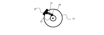
図3〜図6は、本考案の一実施形態を示している。これらの図に示すように、ばね14は、第1のシャーシ12と、この第1のシャーシ12の回りを回転可能である第2のシャーシ13とを相互に連結している。第2のシャーシ13は座席15及びハンドル17を備えている。ばね14は、第1のシャーシ12の回りにおける第2のシャーシ13の進路において、1点(以降、最適点)のみがばねの両端間における最小距離を有するように構成されている(図4及び図5に示されている)。進路上の(図3及び図6に示される)他のいかなる点においても、最適点に向かってシャーシを駆動しようとこのシャーシに印加される力が生じることとなる。第1のシャーシ12上に位置するばねの端は、電気モータ16のシャフト上の鋭い突起18に接続されている。電気モータ16は、突起18の位置、従ってばね14の両端間の最小距離の経路状の点、即ち最適点、を制御する。電気モータ16は、最適点の位置を算出するコンピュータ(図示せず)によって制御される。コンピュータの決定は、センサの読み取り値に基づいている。第2のシャーシ13上に配置される加速度計19は、重力、遠心力、加速力及び減速力による力を測定する。センサの読み取り値から、合成力が第1のシャーシ及び第2のシャーシ間の結合中心を指していないことを示している場合、コンピュータは、センサによって測定された合成力が再び結合中心を指す位置(新しい最適点)へ第2のシャーシが動くことを支援する力を生成するようにシャフトを回転させる。例えば、合成力が結合中心の左を指している場合、シャフトを右に回転して第2のシャーシを右に回転する力を生成する。第2のシャーシが右に回転すると、合成力はより右を指すこととなる。
3 to 6 show an embodiment of the present invention. As shown in these drawings, the
図9は、傾斜角が加速度計19からの読み取り値に基づいている実施形態を示している。合成力が第1のシャーシ12及び第2のシャーシ13を相互接続している結合点23を指していないことを加速度計の読み取り値が示す場合、電気モータ16は第2のシャーシ13及び第1のシャーシ12間の傾斜角を変化させ、合成力が結合点を指すようにする。例えば、検出された合成力が結合点の左を指している場合、電気モータは第2のシャーシを右に傾け、合成力がより右を指すようにする。
FIG. 9 shows an embodiment in which the tilt angle is based on readings from the
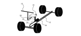
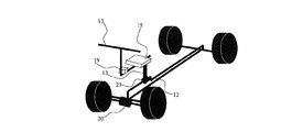
図8は、第2のシャーシ13上に位置する運転席15を示している。ローラ22は、第1のシャーシ12に取り付けられたレール21内/その上面上に配置されている。レール21の湾曲がこのレールに沿ったあらゆる位置における座席の傾斜角度を規定する。この特定の実施形態において、座席面に垂直の方向が上述の結合点と考えられる左右対称のレールの中心を向いている。
FIG. 8 shows the driver's
図10は、前輪の角度が加速度計19からの読み取り値に基づいている実施形態を示している。合成力が第1のシャーシ12及び第2のシャーシ13間の結合点23を指していないことを加速度計の読み取り値が示す場合、電気モータ20は自在軸受け式の車輪の方向を変化させ、合成力が結合点を指すようにする。例えば、検出された合成力が結合点の左を指している場合、電気モータ20は車輪を左に回して遠心力をより右に変化させることにより合成力がより右を指すようにする。傾斜角を変化させることにより、合成力上の重力ベクトルも変化する。
FIG. 10 shows an embodiment in which the front wheel angle is based on readings from the
非均衡(不安定)を検出するアルゴリズムは、以下の通りである。本考案によれば、運転者(第2のシャーシ)が変位する/傾くべき角度及び速度は、そのための機構によって再度決定される。この機構の動作目的は、第2のシャーシ(運転者)を第1のシャーシに対して(機構によって算出された)最適位置に支持するために、安定化手段を構成することである。 The algorithm for detecting imbalance (unstable) is as follows. According to the invention, the angle and speed at which the driver (second chassis) is to be displaced / tilted is again determined by the mechanism for it. The operating purpose of this mechanism is to configure the stabilizing means to support the second chassis (driver) in an optimal position (calculated by the mechanism) relative to the first chassis.
なお、図7に示すように、第2のシャーシが長手方向に傾斜可能であっても良い。 As shown in FIG. 7, the second chassis may be tiltable in the longitudinal direction.
図11は、本考案のコンピュータ化されたシステムを示している。力センサ110/210/310は、第2のシャーシの非均衡状態を検出するように構成されている。この状態は、第2のシャーシに印加される横方向/前方向/後方向の力を測定することにより示すことができる。マイクロコントローラユニット(MCU)120、220及び320は、センサ110/210/310から信号を受信し、アクチュエータ130、230及び330にあらかじめプログラムされた動作を開始させる。特に、MCU120は、安定化機構140に機械的に接続されているアクチュエータ130を制御する。アクチュエータ130は、運転者が、第2のシャーシに印加される力が均衡する第2のシャーシ位置を保持することを支援する点で/方法で第2のシャーシを支持するように安定化機構を構成する。方向及び速度制御機構240は、MCU220により制御されるアクチュエータ230によって作動せしめられる。アクチュエータ230は、力の影響を最小化する/均衡を復元する方向に車輪を回転させる。アクチュエータ230は、力の影響を最小化する/均衡を復元する方法で、車両の加速/減速を行う。第2のシャーシ制御機構340は、力の影響を最小化する/均衡を復元する方法で第2のシャーシを横方向/前方向/後方向に傾かせるアクチュエータ330によって作動せしめられる。
FIG. 11 shows the computerized system of the present invention. The
上述の実施形態の変更態様においては、例えば運転者のハーネス若しくは座席に又はハンドルに位置するセンサによって、車両の方向若しくは速度を傾かせる又は変化させるという運転者の意志についても知ることもできる。これにより、システムは、第2のシャーシを傾ける、若しくは第2のシャーシを傾けることを支援する、又は車両の方向若しくは速度を変化させる。例えば、第2のシャーシが均衡を保つ状況でありかつシステムが運転者が左に傾きたいことを感知した場合、システムは例えば電気モータ(図9)を使用して第2のシャーシを傾け、第2のシャーシを非均衡にし、これにより、運転者は、第2のシャーシ上の力の釣合いをとるべく重力及び遠心力の支援を得るために、車輪を左に向ける。 In the modification of the above-described embodiment, it is possible to know the driver's will to incline or change the direction or speed of the vehicle, for example, by a sensor located in the driver's harness or seat or on the steering wheel. This causes the system to tilt the second chassis, assist in tilting the second chassis, or change the direction or speed of the vehicle. For example, if the second chassis is in a balanced situation and the system senses that the driver wants to lean to the left, the system tilts the second chassis using, for example, an electric motor (FIG. 9) The two chassis are unbalanced, which causes the driver to turn the wheels to the left to obtain gravity and centrifugal assistance to balance the forces on the second chassis.
本考案の一実施形態によれば、車輪の傾斜角及び方向を制御するシステムは、第2のシャーシが均衡を保ちかつ座席のセンサによって運転者が左に傾きたいことを感知した状況において、第2のシャーシを傾けて第2のシャーシを非均衡にし、これにより、システムは、第2のシャーシ上の力の釣合いをとるべく重力及び遠心力の支援を得るために、車輪を左に向ける。 According to one embodiment of the present invention, a system for controlling the tilt angle and direction of a wheel is provided in a situation where the second chassis is balanced and the seat sensor senses that the driver wants to tilt left. Tilt the two chassis to unbalance the second chassis so that the system turns the wheels to the left to obtain gravity and centrifugal assistance to balance the forces on the second chassis.
不安定な車両の動きは、重力、遠心力、意図された加速、意図された減速以外の力から発生し、車両のシャーシに影響を及ぼす動きであると規定される。これらの力は、非平坦な道路、風、エンジン振動等の結果であり得る。これらの力は、特に、重力、遠心力、加速又は減速を検出するために実際に使用される場合、例えば加速度計(又はジャイロ)により検出されるであろう。上述した機構は、検出された信号がノイズであり機構の作動に影響を及ぼさないことを考慮してその動作を規制すべきである。本考案の他の態様として、検出された信号が異常な状況(例えばグリップの損失)を示す場合がある。この場合、上述した機構は、運転者の傾斜角を変化させるか、ステアリングホイールの角度を変化させるか、又は速度を変化させるに動作する。 Unstable vehicle motion is defined as motion that occurs from forces other than gravity, centrifugal force, intended acceleration, and intended deceleration, and that affects the vehicle chassis. These forces can be the result of uneven roads, winds, engine vibrations, and the like. These forces will be detected, for example, by an accelerometer (or gyro), especially when actually used to detect gravity, centrifugal force, acceleration or deceleration. The mechanism described above should regulate its operation taking into account that the detected signal is noise and does not affect the operation of the mechanism. As another aspect of the present invention, the detected signal may indicate an abnormal situation (eg, grip loss). In this case, the mechanism described above operates to change the driver's tilt angle, change the steering wheel angle, or change the speed.
上述した機構の特定の実施態様において、例えば、ステアリング角度、第1及び第2のシャーシ間の角度、並びに車両の速度に基づく力を推測しようとして、上述の機構が第1のシャーシ及び仮想レベル表面(重力の方向を表す)間の角度を無視した場合、上述した仮想レベル表面、即ち重力(遠心力、加速及び減速も同様)の方向に対する運転者の角度を知ることについての機構の動作不履行によって、誤りが発生するであろう。このような問題を救済するために、センサ(例えばジャイロ)を第1のシャーシに設け、第1のシャーシ及び上述の仮想レベル表面間の角度を検出するように構成する。 In certain embodiments of the mechanism described above, the mechanism described above may be used to infer a force based on, for example, the steering angle, the angle between the first and second chassis, and the vehicle speed, and the first chassis and virtual level surface. Neglecting the angle between (representing the direction of gravity), the failure of the mechanism to know the driver's angle relative to the virtual level surface described above, ie the direction of gravity (same for centrifugal force, acceleration and deceleration) An error will occur. In order to remedy such a problem, a sensor (for example, a gyro) is provided in the first chassis and configured to detect an angle between the first chassis and the above-described virtual level surface.
本考案の実施形態における動作例を以下に説明する。 An operation example in the embodiment of the present invention will be described below.
第2のシャーシ上で測定される力は運転者について測定される力を表している。車両は、合成力(重力、遠心力、加速及び減速の合成)が第2のシャーシ上の座席から第1のシャーシ及び第2のシャーシの実際の/仮想の結合部(結合点)に向かっているときに均衡している。運転者が自身の質量中心を変化させ、第2のシャーシを非均衡に動かすと、加速度計は合成力が変化したことを検知する。コンピュータは加速度計を読み取り、その読み取り値は、均衡のとれた車両に対応するあらかじめ調整された力とは異なる合成力であることを示す。コンピュータは、ステアリングホイール、加速又は減速を制御することによって、車両の動きを制御する。コンピュータは、均衡を回復するための力を車両に印加するために、車両の動きを変化させる。 The force measured on the second chassis represents the force measured for the driver. The vehicle has a combined force (combination of gravity, centrifugal force, acceleration and deceleration) from the seat on the second chassis toward the actual / virtual connection (connection point) of the first chassis and the second chassis. When you are balanced. If the driver changes his / her center of mass and moves the second chassis out of balance, the accelerometer detects that the resultant force has changed. The computer reads the accelerometer and indicates that the reading is a resultant force that is different from the pre-adjusted force corresponding to the balanced vehicle. The computer controls the movement of the vehicle by controlling the steering wheel, acceleration or deceleration. The computer changes the movement of the vehicle to apply a force to the vehicle to restore balance.
以上述べた実施形態は全て本考案を例示的に示すものであって限定的に示すものではなく、本考案は他の種々の変形態様及び変更態様で実施することができる。従って本考案の範囲は実用新案登録請求の範囲及びその均等範囲によってのみ規定されるものである。 The above-described embodiments are all illustrative of the present invention and are not limited, and the present invention can be implemented in various other modifications and changes. Therefore, the scope of the present invention is defined only by the scope of the utility model registration request and its equivalent scope.
1 車輪
2、12 第1のシャーシ
3、15 座席
4、23 結合点
5、13 第2のシャーシ
6 運転者
7 重心
8 合成力
9 重力
10 遠心力
14 ばね
16、20 電気モータ
17 ハンドル
18 突起
19 加速度計
21 レール
22 ローラ
110、210、310 力センサ
120、220、320 MCU
130、230、330 アクチュエータ
140 安定化機構
240 方向及び速度制御機構
340 第2のシャーシ制御機構
DESCRIPTION OF SYMBOLS 1
130, 230, 330
本考案は、モーターバイクがそのライダーによって操作されるのと同様に運転者が車両を操作するような車両を構築する機会を与えるものである。同時に、本考案は、車両の設計者に、例えば3つ、4つ若しくはそれ以上又はそれより少ない車輪又はスキーを有する車両を設計する自由度を与える。その場合、サスペンションの構成及び車輪の配置は最適な状態を維持し、運転者の位置、車輪の指示方向又は他の任意の重要でないパラメータの影響を必ずしも受けない。サスペンションの構成及び車輪の配置は、例えば、自動車のサスペンション及び車輪と同様に設計される。これは、1つのシャーシのピッチ、ヨー又はロールが他のシャーシに対して最小の影響を与えるように、全てのサスペンション、車輪又はスキーを担持しているシャーシの動きを運転者を担持しているシャーシの動きから可能な限り切り離すことにより達成される。同時に、第2のシャーシ及び運転者の質量中心の水平ベクトルが、求心力、加速力又は減速力の水平ベクトルと同じ方向に動く。これは、傾きの機能がない同様の車両と比較して、車両に作用するロールトルクを減少させる。 The present invention provides an opportunity to build a vehicle in which a driver operates the vehicle in the same way that a motorbike is operated by its rider. At the same time, the present invention gives the vehicle designer the freedom to design a vehicle with, for example, 3, 4 or more wheels or skis. In that case, construction and arrangement of the wheel suspension to maintain optimal conditions, the driver's position, parameters influence not Na necessarily undergone a non wheels indicated direction, or any other important. The configuration of the suspension and the arrangement of the wheels are designed, for example, in the same manner as the suspension and wheels of an automobile. This carries the driver the movement of the chassis carrying all suspensions, wheels or skis so that the pitch, yaw or roll of one chassis has the least impact on the other chassis. This is accomplished by separating as much as possible from the movement of the chassis. At the same time, the horizontal vector of the second chassis and the driver's center of mass moves in the same direction as the horizontal vector of the centripetal force, acceleration force or deceleration force. This reduces the roll torque acting on the vehicle as compared to a similar vehicle without a tilt function.
図3〜図6は、本考案の一実施形態を示している。これらの図に示すように、ばね14は、第1のシャーシ12と、この第1のシャーシ12の回りを回転可能である第2のシャーシ13とを相互に連結している。第2のシャーシ13は座席15及びハンドル17を備えている。ばね14は、第1のシャーシ12の回りにおける第2のシャーシ13の進路において、1点(以降、最適点)のみがばねの両端間における最小距離を有するように構成されている(図4及び図5に示されている)。進路上の(図3及び図6に示される)他のいかなる点においても、最適点に向かってシャーシを駆動しようとこのシャーシに印加される力が生じることとなる。第1のシャーシ12上に位置するばねの端は、電気モータ16のシャフト上の鋭い突起18に接続されている。電気モータ16は、突起18の位置、従ってばね14の両端間の最小距離の経路上の点、即ち最適点、を制御する。電気モータ16は、最適点の位置を算出するコンピュータ(図示せず)によって制御される。コンピュータの決定は、センサの読み取り値に基づいている。第2のシャーシ13上に配置される加速度計19は、重力、遠心力、加速力及び減速力による力を測定する。センサの読み取り値から、合成力が第1のシャーシ及び第2のシャーシ間の結合中心を指していないことを示している場合、コンピュータは、センサによって測定された合成力が再び結合中心を指す位置(新しい最適点)へ第2のシャーシが動くことを支援する力を生成するようにシャフトを回転させる。例えば、合成力が結合中心の左を指している場合、シャフトを右に回転して第2のシャーシを右に回転する力を生成する。第2のシャーシが右に回転すると、合成力はより右を指すこととなる。
3 to 6 show an embodiment of the present invention. As shown in these drawings, the
Claims (17)
(b)運転者を支持すると共に前記第1のシャーシに可動結合するように構成され、前記道路とは機械的に接触しない第2のシャーシと、
(c)車両の動きを制御するように構成された少なくとも1つの機構と
を備えており、
前記第2のシャーシに印加されかつ前記第1のシャーシ及び前記第2のシャーシ間の結合点を向く力の合成ベクトルを前記運転者が維持可能であり、これにより、前記第2のシャーシ及び前記運転者の質量中心の直線的変位の水平成分が求心力、加速力又は減速力の水平成分と同一の方向を向くように、前記機構が、前記第2のシャーシ及び前記運転者の身体の変化位置に非弾性的に反応するように構成されていることを特徴とする運転者によって制御される車両。 (A) a first chassis supported by a road;
(B) a second chassis configured to support the driver and to be movably coupled to the first chassis, and not to mechanically contact the road;
(C) at least one mechanism configured to control movement of the vehicle,
The driver can maintain a combined vector of forces applied to the second chassis and directed to a connection point between the first chassis and the second chassis, whereby the second chassis and the The mechanism is adapted to change the position of the body of the second chassis and the driver so that the horizontal component of the linear displacement of the driver's center of mass is oriented in the same direction as the horizontal component of the centripetal force, acceleration force or deceleration force. A vehicle controlled by a driver, characterized in that the vehicle is configured to react inelastically.
(b)運転者を支持すると共に前記第1のシャーシに可動結合するように構成され、前記道路とは機械的に接触しない第2のシャーシと、
(c)車両の動きを制御するように構成された少なくとも1つの機構と
を備えており、
前記機構が、前記第2のシャーシに印加されかつ前記第1のシャーシ及び前記第2のシャーシ間の結合点を向く力の合成ベクトルを前記運転者が維持可能であり、これにより、前記第2のシャーシ及び前記運転者の質量中心の直線的変位の水平成分が求心力、加速力又は減速力の水平成分と同一の方向を向くように構成されていることを特徴とする運転者によって制御される車両。 (A) a first chassis supported by a road;
(B) a second chassis configured to support the driver and to be movably coupled to the first chassis, and not to mechanically contact the road;
(C) at least one mechanism configured to control movement of the vehicle,
The mechanism can maintain a combined vector of forces applied to the second chassis and directed toward a connection point between the first chassis and the second chassis, whereby the second The horizontal component of the linear displacement of the chassis and the center of mass of the driver is oriented in the same direction as the horizontal component of the centripetal force, acceleration force or deceleration force, and is controlled by the driver vehicle.
Applications Claiming Priority (2)
| Application Number | Priority Date | Filing Date | Title |
|---|---|---|---|
| US13/742,719 | 2013-01-16 | ||
| US13/742,719 US20130131923A1 (en) | 2008-07-01 | 2013-01-16 | Vehicle and method of controlling thereof |
Publications (1)
| Publication Number | Publication Date |
|---|---|
| JP3187004U true JP3187004U (en) | 2013-11-07 |
Family
ID=48784203
Family Applications (1)
| Application Number | Title | Priority Date | Filing Date |
|---|---|---|---|
| JP2013002616U Expired - Fee Related JP3187004U (en) | 2013-01-16 | 2013-05-13 | Vehicle controlled by the driver |
Country Status (3)
| Country | Link |
|---|---|
| JP (1) | JP3187004U (en) |
| DE (1) | DE202013102061U1 (en) |
| IT (1) | ITMI20130176U1 (en) |
-
2013
- 2013-05-08 IT IT000176U patent/ITMI20130176U1/en unknown
- 2013-05-12 DE DE202013102061U patent/DE202013102061U1/en not_active Expired - Lifetime
- 2013-05-13 JP JP2013002616U patent/JP3187004U/en not_active Expired - Fee Related
Also Published As
| Publication number | Publication date |
|---|---|
| ITMI20130176U1 (en) | 2014-07-17 |
| DE202013102061U1 (en) | 2013-06-07 |
Similar Documents
| Publication | Publication Date | Title |
|---|---|---|
| CN108025785B (en) | Vehicle with a steering wheel | |
| US10207762B2 (en) | Mobile body | |
| US8831833B2 (en) | Vehicle | |
| JP5413377B2 (en) | vehicle | |
| US8225891B2 (en) | Inverted pendulum mobile vehicle | |
| US20130131923A1 (en) | Vehicle and method of controlling thereof | |
| WO2017164342A1 (en) | Leaning posture control device for leaning vehicle having left and right inclined wheels mounted thereon and leaning vehicle having left and right inclined wheels mounted thereon | |
| JP6478743B2 (en) | Moving body | |
| CN1918013A (en) | Multitrack curve-tilting vehicle, and method for tilting a vehicle | |
| WO2017183639A1 (en) | Leaning vehicle | |
| WO2019245042A1 (en) | Vehicle | |
| JP2012011996A (en) | Vehicle | |
| JP6898428B2 (en) | vehicle | |
| JP2011230727A (en) | Vehicle | |
| US20110118944A1 (en) | Vehicle and Method of Controlling Thereof | |
| JP2013112238A (en) | Vehicle | |
| JP6277404B2 (en) | Automobile | |
| JP2007118807A (en) | Vehicle | |
| CN111278724A (en) | Vehicle with a steering wheel | |
| JP3187004U (en) | Vehicle controlled by the driver | |
| JP6599110B2 (en) | vehicle | |
| JP6355380B2 (en) | Vehicle support | |
| WO2019102997A1 (en) | Vehicle | |
| WO2023144922A1 (en) | Tilting vehicle | |
| WO2024048532A1 (en) | Leaning vehicle |
Legal Events
| Date | Code | Title | Description |
|---|---|---|---|
| R150 | Certificate of patent or registration of utility model |
Free format text: JAPANESE INTERMEDIATE CODE: R150 |
|
| LAPS | Cancellation because of no payment of annual fees |