JP3174511U - Light-emitting diode luminaire - Google Patents
Light-emitting diode luminaire Download PDFInfo
- Publication number
- JP3174511U JP3174511U JP2012000110U JP2012000110U JP3174511U JP 3174511 U JP3174511 U JP 3174511U JP 2012000110 U JP2012000110 U JP 2012000110U JP 2012000110 U JP2012000110 U JP 2012000110U JP 3174511 U JP3174511 U JP 3174511U
- Authority
- JP
- Japan
- Prior art keywords
- light
- emitting diode
- shade
- accommodation space
- opening
- Prior art date
- Legal status (The legal status is an assumption and is not a legal conclusion. Google has not performed a legal analysis and makes no representation as to the accuracy of the status listed.)
- Expired - Fee Related
Links
Images




Landscapes
- Non-Portable Lighting Devices Or Systems Thereof (AREA)
Abstract
【課題】光度を増加してゴーストを除去できる発光ダイオード照明器具を提供する。
【解決手段】光度を増加してゴーストを除去できる発光ダイオード照明器具において、複数の反射用コップ23が設けられており、複数の反射用コップ23は、凹み状を呈し、収容空間24を有し、収容空間24に少なくとも一つの発光ダイオード40が設けられ、収容空間24の底部に貫通孔28が設けられ、収容空間24の貫通孔28から遠ざかった一端に開口27が設けられ、開口27が位置する平面を光線出力面271とされる笠20と、笠20の光線出力面271を覆うように設けられ、透光であり、その表面に複数の突起11が設けられる拡散フィルム10と、笠20の下方に設けられ、貫通孔28を挿通する少なくとも一つの発光ダイオード40が電気的に接続している回路板30と、を含む。
【選択図】図1A light-emitting diode luminaire that can increase luminosity and remove ghosts is provided.
In a light-emitting diode illuminator capable of increasing luminosity and removing a ghost, a plurality of reflection cups 23 are provided, and the plurality of reflection cups 23 have a concave shape and have an accommodation space 24. At least one light emitting diode 40 is provided in the accommodation space 24, a through hole 28 is provided at the bottom of the accommodation space 24, an opening 27 is provided at one end away from the through hole 28 of the accommodation space 24, and the opening 27 is positioned. The light-shade 20 is a light-beam output surface 271, and the light-transmitting surface 271 is provided so as to cover the light-beam output surface 271. , And a circuit board 30 to which at least one light emitting diode 40 inserted through the through hole 28 is electrically connected.
[Selection] Figure 1
Description
本考案は、照明器具の笠に関し、特に、光度を増加してゴーストを除去できる発光ダイオード照明器具に関するものである。 The present invention relates to a shade for a lighting fixture, and more particularly, to a light-emitting diode lighting fixture capable of increasing a luminous intensity and removing a ghost.
従来の照明器具は、体積がより大きいため、その設置台の高さが高くなる。これにより、従来の照明器具は伝統的な笠を使用する。この伝統的な笠は、深さがより浅く、茶碗状を呈し、長時間利用されると高温になる。また、複数の伝統的な笠を配列して構成されるユニットによると、ゴーストが発生する。そして従来の照明器具は、よく輝くため、ユーザの目が疲労しやすい。 Since the conventional lighting fixture has a larger volume, the height of the installation base becomes high. As a result, conventional lighting fixtures use traditional shades. This traditional shade is shallower, has a bowl shape and becomes hot when used for a long time. In addition, a ghost is generated according to a unit configured by arranging a plurality of traditional shades. And since the conventional lighting fixture shines well, a user's eyes are easy to get tired.
なお、発光ダイオードの発光方式及び電力供給方式は、従来の照明器具と異なるため、全体の照明設計を従来と異なるものを採用することができる。発光ダイオードは体積が小さく光度が高いため、従来の笠を流用すると、発光ダイオードからの光線が八方に放射され、ユーザがこの光線を見ると、目に不快感を覚える。従来の照明器具では、発光ダイオードの組数を増加することにより光度を増加でき、消耗電力を減少でき、高温性質を改善した。しかし、散乱が原因でゴーストを除去できないという問題があった。 In addition, since the light emission method and power supply method of a light emitting diode differ from the conventional lighting fixture, what differs from the conventional illumination design can be employ | adopted for the whole illumination design. Since the light emitting diode has a small volume and a high luminous intensity, when a conventional shade is used, a light beam from the light emitting diode is emitted in all directions, and the user feels uncomfortable when viewing the light beam. In the conventional lighting fixture, the luminous intensity can be increased by increasing the number of sets of light emitting diodes, the power consumption can be reduced, and the high temperature property is improved. However, there is a problem that ghosts cannot be removed due to scattering.
本考案の主な目的は、光度を増加してゴーストを除去できる発光ダイオード照明器具を提供することにある。 The main object of the present invention is to provide a light-emitting diode luminaire that can increase luminosity and remove ghosts.
本考案の発光ダイオード照明器具によると、光度を増加してゴーストを除去できる発光ダイオード照明器具において、複数の反射用コップ23が設けられており、複数の反射用コップ23は、凹み状を呈し、収容空間24を有し、収容空間24に少なくとも一つの発光ダイオード40が設けられ、収容空間24の底部に貫通孔28が設けられ、収容空間24の貫通孔28から遠ざかった一端に開口27が設けられ、開口27が位置する平面を光線出力面271とされる笠20と、笠20の光線出力面271を覆うように設けられ、透光であり、その表面に複数の突起11が設けられる拡散フィルム10と、笠20の下方に設けられ、貫通孔28を挿通する少なくとも一つの発光ダイオード40が電気的に接続している回路板30と、を含むことを特徴とする。
According to the light-emitting diode illuminator of the present invention, in the light-emitting diode illuminator that can increase luminosity and remove ghosts, a plurality of reflecting
本考案の発光ダイオード照明器具によると、発光ダイオード40の表面には、更に、集光マスク29が設けられることを特徴とする。
According to the light-emitting diode illuminating device of the present invention, a
本考案の発光ダイオード照明器具によると、反射用コップ23の内部には、複数本の突出する反射紋様21が設けられることを特徴とする。
According to the light-emitting diode illuminating device of the present invention, a plurality of protruding
本考案の発光ダイオード照明器具によると、笠20の外部には、複数本の支持枠25が設けられ、螺子251により支持枠25が回路板30に締結されることを特徴とする。
According to the light-emitting diode illuminator of the present invention, a plurality of
本考案の発光ダイオード照明器具によると、回路板30は、上面301と、下面302と、を有し、上面301に発光ダイオード40が連結されていることを特徴とする。
According to the light emitting diode lighting apparatus of the present invention, the
本考案の発光ダイオード照明器具によると、回路板30の下面302には、一セットの放熱フィン32が設けられることを特徴とする。
According to the light-emitting diode illuminator of the present invention, a set of
本考案の発光ダイオード照明器具によると、笠20の全面には、アルミ鍍金層201が設けられていることを特徴とする。
According to the light-emitting diode luminaire of the present invention, an
本考案の発光ダイオード照明器具によると、笠20の内部には、透光できない反射鏡面22が設けられ、反射鏡面22により複数の反射用コップ23が隔離されることを特徴とする。
According to the light-emitting diode illuminating device of the present invention, a
本考案の発光ダイオード照明器具によると、開口27の長さLは、開口27から貫通孔28までの距離Dと同じであることを特徴とする。
According to the light-emitting diode luminaire of the present invention, the length L of the
本考案の発光ダイオード照明器具によると、収容空間24の開口27に近接する箇所では、光線出力面271と垂直に反射面241が形成されることを特徴とする。
According to the light-emitting diode illuminator of the present invention, the
本考案の発光ダイオード照明器具によれば、光度を増加してゴーストを除去できるという効果がある。 According to the light-emitting diode luminaire of the present invention, there is an effect that the ghost can be removed by increasing the luminous intensity.
以下、本考案の実施の形態を図面に基づいて説明する。 Hereinafter, embodiments of the present invention will be described with reference to the drawings.
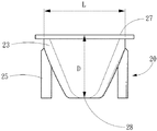
まず、図1乃至図4を参照する。図1は本考案の一実施例の構成を示す分解斜視図であり、図2は本考案の笠の構成を示す上面図、図3本考案の笠の構成を示す側面図、図4は本考案の一実施例の構成を示す縦断面図である。本考案の一実施例の発光ダイオード照明器具は、笠20と、拡散フィルム10と、回路板30と、を含む。笠20の内部には、透光できない反射鏡面22が設けられる。反射鏡面22により、隣接する光源は互いに散乱せず、複数の反射用コップ23はそれぞれ隔離される。
First, FIG. 1 to FIG. 4 will be referred to. 1 is an exploded perspective view showing the configuration of an embodiment of the present invention, FIG. 2 is a top view showing the configuration of the shade of the present invention, FIG. 3 is a side view showing the configuration of the shade of the present invention, and FIG. It is a longitudinal cross-sectional view which shows the structure of one Example of invention. The light-emitting diode luminaire according to an embodiment of the present invention includes a
反射用コップ23は、凹み状を呈し、収容空間24を有する。収容空間24には、少なくとも一つの発光ダイオード40が設けられる。収容空間24の底部に貫通孔28が設けられる。貫通孔28を挿通する少なくとも一つの発光ダイオード40は、回路板30と電気的に接続している。収容空間24の貫通孔28から遠ざかった一端に開口27が設けられる。開口27が位置する平面が光線出力面271とされる。そして、図3に示すように、開口27の長さLは、開口27から貫通孔28までの距離Dと同じである。このように、光線の経路を最適にすることができる。
The
また、収容空間24の開口27に近接する箇所では、光線出力面271と垂直に反射面241が形成される。反射面241により、光線の経路を制限でき、光線の散乱を回避できる。
In addition, a
笠20の全面には、アルミ鍍金層201が設けられており、アルミ鍍金層201は銀色である。アルミ鍍金層201により、光線の反射を増加できる。本考案の一実施例の発光ダイオード照明器具によれば、反射鏡面22により、隣接する発光ダイオード40からの光線の散乱を減少でき、反射用コップ23が凹み状を呈することにより、発光ダイオード40からの光線を集光でき、そして反射用コップ23の内部には、複数本の突出する反射紋様21が設けられることにより、光線の反射を増加できる。
An
拡散フィルム10は、光線出力面271をカバーする。拡散フィルム10の機能により、光が均一な面状光源を提供する。拡散フィルム10は、その基材に多数の粒が設けられており、前記粒が散乱粒子とされる。光線は、拡散フィルム10を通過する間に、屈折率が異なる二つの媒質を繰り返し通過するため、光学的な拡散の効果を達成できる。拡散フィルム10は、透明であり、複数の透明な突起11を含むため、光線が拡散フィルム10を通過しているときには、突起11により光線が均一に分布するようになる。これにより、複数組の光源による拡散及び反射を減少できる。
The
発光ダイオード照明器具は、発光ダイオード40の光度が高いため、放熱性が極めて重要である。本考案は、笠20の周りに複数の支持枠25が設けられ、螺子251により支持枠25が回路板30に締結される。回路板30は、上面301と、下面302と、を有し、上面301に発光ダイオード40が連結されている。回路板30の下面302には、一セットの放熱フィン32が設けられる。一セットの放熱フィンとは、回路板30に対して2以上の放熱フィンが集合した構成を意味するものである。反射用コップ23は、回路板30を介して放熱フィン32と連結する。これにより、発光ダイオード40からの熱を素早く放熱できる。そして発光ダイオード40の表面に設けられる集光マスク29により、発光特性を強化できる。
In the light-emitting diode illuminating device, heat dissipation is extremely important because the light-emitting
図5を参照する。図5は本考案の一実施例により光度を増加してゴーストを除去することを示す模式図(一)である。発光ダイオード40から光線50が放射されるときに、光線50は、反射用コップ23に進入して、突起11、反射鏡面22及び集光マスク29に重複して反射され、集光し、光線出力面271へ放射される。このように、光線出力面271を経由する光線50が重複して反射され、集光するため、光が均一に分布する光源を形成でき、これにより、光度を増加してゴーストを除去できる。
Please refer to FIG. FIG. 5 is a schematic diagram (1) showing that the ghost is removed by increasing the luminous intensity according to one embodiment of the present invention. When the
図6を参照する。図6は本考案の一実施例により光度を増加してゴーストを除去することを示す模式図(二)である。本考案では、集光マスク29を使用しなくてもよい。集光マスク29を使用する目的は、発光ダイオードからの光線の放射する角度を制御できることにある。しかし、集光マスク29を使用しなくても、反射鏡面22の反射により集光効果を得ることができる。
Please refer to FIG. FIG. 6 is a schematic diagram (2) showing that a ghost is removed by increasing luminous intensity according to an embodiment of the present invention. In the present invention, the condensing
本考案の最良の実施の形態について説明したが、当業者には明らかなように、本考案の精神を逸脱しない範囲で実施の形態を変形することが可能であり、そのような実施の形態は本考案の範囲に属するものである。 Although the best embodiment of the present invention has been described, it will be apparent to those skilled in the art that the embodiment can be modified without departing from the spirit of the present invention. It belongs to the scope of the present invention.
本考案は、照明器具に適用することができる。 The present invention can be applied to lighting equipment.
10 拡散フィルム
11 突起
20 笠
22 反射鏡面
23 反射用コップ
24 収容空間
25 支持枠
27 開口
28 貫通孔
29 集光マスク
30 回路板
32 放熱フィン
40 発光ダイオード
50 光線
201 アルミ鍍金層
241 反射面
251 螺子
271 光線出力面
301 上面
302 下面
D 距離
L 長さ
DESCRIPTION OF
Claims (10)
複数の反射用コップ(23)が設けられており、前記複数の反射用コップ(23)は、凹み状を呈し、収容空間(24)を有し、前記収容空間(24)に少なくとも一つの発光ダイオード(40)が設けられ、前記収容空間(24)の底部に貫通孔(28)が設けられ、前記収容空間(24)の前記貫通孔(28)から遠ざかった一端に開口(27)が設けられ、前記開口(27)が位置する平面を光線出力面(271)とされる笠(20)と、
前記笠(20)の前記光線出力面(271)を覆うように設けられ、透光であり、その表面に複数の突起(11)が設けられる拡散フィルム(10)と、
前記笠(20)の下方に設けられ、前記貫通孔(28)を挿通する少なくとも一つの前記発光ダイオード(40)が電気的に接続している回路板(30)と、
を含むことを特徴とする発光ダイオード照明器具。 In a light-emitting diode luminaire that can increase luminosity and remove ghosts,
A plurality of reflection cups (23) are provided, and the plurality of reflection cups (23) have a concave shape, have an accommodation space (24), and at least one light emission in the accommodation space (24). A diode (40) is provided, a through hole (28) is provided at the bottom of the accommodation space (24), and an opening (27) is provided at one end of the accommodation space (24) away from the through hole (28). A shade (20) in which the plane on which the opening (27) is located is a light output surface (271);
A diffusion film (10) that is provided so as to cover the light output surface (271) of the shade (20), is translucent, and has a plurality of protrusions (11) on its surface;
A circuit board (30) provided below the shade (20) and electrically connected to at least one of the light emitting diodes (40) inserted through the through hole (28);
A light-emitting diode luminaire comprising:
Priority Applications (1)
| Application Number | Priority Date | Filing Date | Title |
|---|---|---|---|
| JP2012000110U JP3174511U (en) | 2012-01-12 | 2012-01-12 | Light-emitting diode luminaire |
Applications Claiming Priority (1)
| Application Number | Priority Date | Filing Date | Title |
|---|---|---|---|
| JP2012000110U JP3174511U (en) | 2012-01-12 | 2012-01-12 | Light-emitting diode luminaire |
Publications (1)
| Publication Number | Publication Date |
|---|---|
| JP3174511U true JP3174511U (en) | 2012-03-22 |
Family
ID=48001652
Family Applications (1)
| Application Number | Title | Priority Date | Filing Date |
|---|---|---|---|
| JP2012000110U Expired - Fee Related JP3174511U (en) | 2012-01-12 | 2012-01-12 | Light-emitting diode luminaire |
Country Status (1)
| Country | Link |
|---|---|
| JP (1) | JP3174511U (en) |
Cited By (2)
| Publication number | Priority date | Publication date | Assignee | Title |
|---|---|---|---|---|
| WO2017018100A1 (en) * | 2015-07-29 | 2017-02-02 | シーシーエス株式会社 | Linear light irradiation device |
| WO2026067770A1 (en) * | 2024-09-29 | 2026-04-02 | 苏州欧普照明有限公司 | Reflector, optical module and lamp |
-
2012
- 2012-01-12 JP JP2012000110U patent/JP3174511U/en not_active Expired - Fee Related
Cited By (3)
| Publication number | Priority date | Publication date | Assignee | Title |
|---|---|---|---|---|
| WO2017018100A1 (en) * | 2015-07-29 | 2017-02-02 | シーシーエス株式会社 | Linear light irradiation device |
| JP2017032288A (en) * | 2015-07-29 | 2017-02-09 | シーシーエス株式会社 | Line light irradiation device |
| WO2026067770A1 (en) * | 2024-09-29 | 2026-04-02 | 苏州欧普照明有限公司 | Reflector, optical module and lamp |
Similar Documents
| Publication | Publication Date | Title |
|---|---|---|
| JP5272029B2 (en) | Lens and lighting device | |
| JP5868106B2 (en) | Lighting device | |
| US20140167593A1 (en) | Led illumination lamp | |
| TW201209348A (en) | LED-lamp | |
| CN102367920A (en) | LED (light emitting diode) wide angle floodlight | |
| CN104676315A (en) | Internal reflection lamp | |
| JP2012064367A (en) | Light source device and self ballasted lighting system | |
| CN105960560A (en) | Lighting device | |
| TW201331510A (en) | Planar LED lighting | |
| KR20110023231A (en) | Stick LED Lighting Fixtures | |
| JP5918835B2 (en) | Lighting device | |
| JP2017016924A (en) | LED lamp | |
| CN201779598U (en) | Optical element and light source comprising same | |
| JP5559649B2 (en) | Lighting device | |
| JP5628655B2 (en) | lighting equipment | |
| JP6892627B2 (en) | Lighting device | |
| KR101509460B1 (en) | Led lighting | |
| TWM423203U (en) | High-brightness LED lamp structure | |
| CN106609919A (en) | Illuminating device | |
| JP3179339U (en) | Light-emitting diode lighting device for ceiling plate | |
| KR20150128203A (en) | Lighting apparatus | |
| TWI468618B (en) | Lens element for light source module and illuminator thereof | |
| JP2014093129A (en) | Light-emitting unit and luminaire | |
| KR101797480B1 (en) | Lighting apparatus | |
| TWM392312U (en) | Bulb structure |
Legal Events
| Date | Code | Title | Description |
|---|---|---|---|
| R150 | Certificate of patent or registration of utility model |
Ref document number: 3174511 Country of ref document: JP Free format text: JAPANESE INTERMEDIATE CODE: R150 Free format text: JAPANESE INTERMEDIATE CODE: R150 |
|
| FPAY | Renewal fee payment (event date is renewal date of database) |
Free format text: PAYMENT UNTIL: 20150228 Year of fee payment: 3 |
|
| R250 | Receipt of annual fees |
Free format text: JAPANESE INTERMEDIATE CODE: R250 |
|
| R250 | Receipt of annual fees |
Free format text: JAPANESE INTERMEDIATE CODE: R250 |
|
| R250 | Receipt of annual fees |
Free format text: JAPANESE INTERMEDIATE CODE: R250 |
|
| R250 | Receipt of annual fees |
Free format text: JAPANESE INTERMEDIATE CODE: R250 |
|
| R250 | Receipt of annual fees |
Free format text: JAPANESE INTERMEDIATE CODE: R250 |
|
| LAPS | Cancellation because of no payment of annual fees |