JP3148481U - nut - Google Patents
nut Download PDFInfo
- Publication number
- JP3148481U JP3148481U JP2008007541U JP2008007541U JP3148481U JP 3148481 U JP3148481 U JP 3148481U JP 2008007541 U JP2008007541 U JP 2008007541U JP 2008007541 U JP2008007541 U JP 2008007541U JP 3148481 U JP3148481 U JP 3148481U
- Authority
- JP
- Japan
- Prior art keywords
- nut
- socket wrench
- insertion hole
- recess
- tool insertion
- Prior art date
- Legal status (The legal status is an assumption and is not a legal conclusion. Google has not performed a legal analysis and makes no representation as to the accuracy of the status listed.)
- Expired - Fee Related
Links
- 230000037431 insertion Effects 0.000 claims abstract description 17
- 238000003780 insertion Methods 0.000 claims abstract description 17
- 239000000758 substrate Substances 0.000 description 5
- 230000002093 peripheral effect Effects 0.000 description 3
Images


Landscapes
- Details Of Spanners, Wrenches, And Screw Drivers And Accessories (AREA)
Abstract
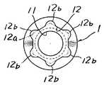
【課題】狭いスペースでもナットを挿入して締め付けできながら、中心に形成する工具挿入用穴により六角ソケットレンチと梅紋形ソケットレンチを締付工具をとして使用できるナットを提供する。【解決手段】内周面にねじ溝11が形成された円筒状ナット1の内周面一端部に、ねじ溝11の外径よりも大きな正六角形状凹所12aとその凹所12aにおける各角部にその角部よりも外側に膨らむ円弧状凹部12bとが連設されてなる工具挿入用穴12を形成した。【選択図】図1A nut capable of using a hexagon socket wrench and a plum-shaped socket wrench as a tightening tool by a tool insertion hole formed in the center while the nut can be inserted and tightened even in a narrow space. A hexagonal recess 12a larger than the outer diameter of the thread groove 11 and each corner of the recess 12a are formed at one end of the inner periphery of a cylindrical nut 1 having a thread groove 11 formed on the inner periphery. A tool insertion hole 12 is formed in which a circular arc-shaped concave portion 12b that swells outward from the corner portion is connected to the portion. [Selection] Figure 1
Description
本考案は、主として狭いスペースにおいて嵌め込み状態で用いられるナットに関する。 The present invention relates to a nut that is used in a state of being mainly fitted in a narrow space.
一般にナットは外周が正六角形状を呈し、その内周面にねじ溝が形成された構成になっている。そして、使用時には、例えばボルトのねじ部にナットのねじ溝を合わせてねじ込み、その後、スパナ等の締付工具或いは電動締付工具などの筒型ソケットをナットの外周に嵌め込み、その状態でこれらの工具によりナットを締付方向に回転させて締結するようになっている。 In general, a nut has a regular hexagonal outer periphery, and a thread groove is formed on the inner peripheral surface thereof. And, in use, for example, align the screw groove of the nut with the screw groove of the bolt and screw in, and then fit a cylindrical socket such as a wrench or tightening tool or electric tightening tool on the outer periphery of the nut, and in these states The nut is rotated by a tool in the tightening direction and tightened.
ところで、上記した従来のナットにあっては、狭いスペース内にナットが埋め込み状態となるようにナットをねじ込んで締結する場合、上記スパナや筒型ソケット等の締付工具をナットの外周に嵌め込んで装着することが困難となり、ナット締めができなくなるといった問題があった。 By the way, in the conventional nut described above, when the nut is screwed and tightened so that the nut is embedded in a narrow space, the tightening tool such as the spanner or the cylindrical socket is fitted on the outer periphery of the nut. This makes it difficult to mount the nut and tightens the nut.
なお、この問題に対して例えば筒状のナットの中心部に角形凹所を設ける一方、断面が角形のソケットレンチを用いて、そのソケットレンチの先端をナットの角形凹所に嵌合し、その状態でソケットレンチと共にナットを締付方向に回転させてボルトに締結するようにしたものがある。しかし、ナットの中心部に角形凹所を設けるタイプにあっては、ナットの締結工具がそのナットの角形凹所に符合する1つの角型ソケットレンチに限定されるものであった。 For this problem, for example, a square recess is provided in the center of the cylindrical nut, while a socket wrench having a square cross section is used, and the tip of the socket wrench is fitted into the square recess of the nut. There is one in which the nut is rotated in the tightening direction together with the socket wrench and fastened to the bolt. However, in the type in which the square recess is provided at the center of the nut, the nut fastening tool is limited to one square socket wrench that matches the square recess of the nut.
そこで、本考案は、狭いスペースでもナットを埋め込み状に挿入して締結できながら、中心に形成する工具挿入用穴により六角ソケットレンチと梅紋形ソケットレンチを締付工具として自由に選択して用いることのできるナットの提供を課題とする。 Therefore, the present invention can select and use a hexagon socket wrench and a plum-shaped socket wrench as a tightening tool by a tool insertion hole formed in the center while being able to insert and tighten a nut in a narrow space even in a narrow space. It is an object to provide a nut that can be used.
上記問題を解決するため本考案は、内周面にねじ溝11が形成された円筒状ナット1の内周面一端部に、ねじ溝11の外径よりも大きな正六角形状凹所12aとその凹所12aにおける各角部にその角部よりも外側に膨らむ円弧状凹部12b…とが連設されてなる工具挿入用穴12を形成したことを特徴とする。 In order to solve the above-described problem, the present invention provides a regular
本考案によれば、上記したように円筒状のナット1であるから、狭いスペースであってもそのスペースへのナット1の挿入が可能であれば、中心に形成した工具挿入用穴12に例えば六角ソケットレンチ7を嵌め込んで該レンチ7を回転操作することにより、ナット1を狭いスペース内に埋め込み状態となるようにねじ込むことができる。しかも、工具挿入用穴12をねじ溝11の外径よりも大きな正六角形状凹所12aとその凹所12aにおける各角部にその角部よりも外側に膨らむ円弧状凹部12b…とが連設された形状としたので、ナット1の締め付け時には、中心に形成した工具挿入用穴12に嵌合する六角ソケットレンチ7の他、上記工具挿入用穴12の形状と同一断面とした梅紋形ソケットレンチ8を締付工具として用いることができる。その結果、複数の締付工具を選択的に用いて幅広く締結することができる。 According to the present invention, since it is the
以下、本考案の実施の形態を図に基づいて説明する。 Hereinafter, embodiments of the present invention will be described with reference to the drawings.
図1及び図2は、本考案に係るナットを示し、このナット1は、円筒状を呈すると共に内周面にねじ溝11が形成されている。 1 and 2 show a nut according to the present invention. The
そして、ナット1の内周面一端部に、ねじ溝11の外径よりも大きな正六角形状凹所12aでその凹所12aにおける各角部にその角部よりも外側に膨らむ円弧状切欠部12b…が連設されてなる、換言すれば梅紋形状を呈してなる工具挿入用穴12が形成されている。 Then, at one end of the inner peripheral surface of the
図3はナットの使用状態を示す説明図で、符号2は基板、3は取付板、4,5は取付板3に突設された突出部材、6は基板2にねじ部61が外方に突出するよう設けられた取付ボルトである。また、図2に及び図3において符号7は六角ソケットレンチであり、さらに、図4において符号8は六角ソケットレンチ7に代えて使用する上記工具挿入用穴12の形状と同一断面とした梅紋形ソケットレンチである。 FIG. 3 is an explanatory view showing the state of use of the nut.
次に、以上のように構成されたナットの作用について説明する。 Next, the operation of the nut configured as described above will be described.
まず、図3に示すように基板2側から外方に突出する取付ボルト6に取付板3をその貫通孔31を介して装着する。次に、六角ソケットレンチ7の先端部をナット1の工具挿入用穴12に嵌め込み、その先端部でナット1を保持した状態のまま突出部材4,5間の狭いスペース間よりナット1を取付ボルト6の先端ねじ部に符合するように挿入する。その後、六角ソケットレンチ7を締め付け方向に回転操作して、ナット1を取付ボルト6にねじ込むことにより、基板2に取付板3を締結することができる。 First, as shown in FIG. 3, the
このように、狭いスペースであってもナット1が円筒状であるからそのスペースへのナット1の挿入が可能であれば、中心に形成した工具挿入用穴12に六角ソケットレンチ7を嵌め込んで該レンチ7を回転操作することにより、ナット1を取付ボルト6にねじ込んで突出部材4,5間の狭いスペース間に埋め込み状態となりながら基板2に取付板3を締結することができる。 Thus, since the
また、ナット1の工具挿入用穴12は、上記したように平面から見たとき梅紋形状を呈しているので、六角ソケットレンチ7に代えて図4に示す上記工具挿入用穴12の形状と同一断面とした梅紋形ソケットレンチ8を締付工具として用いることができる。この梅紋形ソケットレンチ8の場合も、図示していないが六角ソケットレンチ7と同様工具挿入用穴12に梅紋形ソケットレンチ8の先端部を嵌め込み、六角ソケットレンチ7と同様にねじ込むことにより狭いスペースであっても締結できる。これにより、複数の締付工具を自由に用いて幅広く締結することができる。 Moreover, since the
なお、六角ソケットレンチ7及び梅紋形ソケットレンチ8は手動タイプのものであってもよいし、電動ダイプのものであってもよい。 The
1 ナット
11 ねじ溝
12 工具挿入用穴
12a 正六角形状凹所
12b 円弧状凹部1
Claims (1)
Priority Applications (1)
| Application Number | Priority Date | Filing Date | Title |
|---|---|---|---|
| JP2008007541U JP3148481U (en) | 2008-09-29 | 2008-09-29 | nut |
Applications Claiming Priority (1)
| Application Number | Priority Date | Filing Date | Title |
|---|---|---|---|
| JP2008007541U JP3148481U (en) | 2008-09-29 | 2008-09-29 | nut |
Publications (1)
| Publication Number | Publication Date |
|---|---|
| JP3148481U true JP3148481U (en) | 2009-02-19 |
Family
ID=54782028
Family Applications (1)
| Application Number | Title | Priority Date | Filing Date |
|---|---|---|---|
| JP2008007541U Expired - Fee Related JP3148481U (en) | 2008-09-29 | 2008-09-29 | nut |
Country Status (1)
| Country | Link |
|---|---|
| JP (1) | JP3148481U (en) |
Cited By (1)
| Publication number | Priority date | Publication date | Assignee | Title |
|---|---|---|---|---|
| WO2018135107A1 (en) * | 2017-01-20 | 2018-07-26 | 日立オートモティブシステムズ株式会社 | Power steering apparatus |
-
2008
- 2008-09-29 JP JP2008007541U patent/JP3148481U/en not_active Expired - Fee Related
Cited By (3)
| Publication number | Priority date | Publication date | Assignee | Title |
|---|---|---|---|---|
| WO2018135107A1 (en) * | 2017-01-20 | 2018-07-26 | 日立オートモティブシステムズ株式会社 | Power steering apparatus |
| CN110214109A (en) * | 2017-01-20 | 2019-09-06 | 日立汽车系统株式会社 | Power steering apparatus |
| JPWO2018135107A1 (en) * | 2017-01-20 | 2019-12-12 | 日立オートモティブシステムズ株式会社 | Power steering device |
Similar Documents
| Publication | Publication Date | Title |
|---|---|---|
| US20090220321A1 (en) | Fastening metal fitting | |
| JP3159957U (en) | Fasteners | |
| US20080245195A1 (en) | Anti-Slip Socket Capable of Stably Applying Force in Clockwise and Counterclockwise Directions | |
| JP3187298U (en) | Double lock nut | |
| CN110799761B (en) | Fastening device | |
| JP6239696B1 (en) | Cable gland | |
| US20050276677A1 (en) | Load carrier support | |
| US7270032B1 (en) | Fitting hole of a hand tool | |
| JP3155204U (en) | Eccentric lock nut | |
| JPWO2007144946A1 (en) | Fixture | |
| US20100294087A1 (en) | Tool sleeve clamping structure | |
| KR20090006288A (en) | Screw | |
| US10471574B2 (en) | Positioning device for socket | |
| TWI807482B (en) | Multi-grip socket bit | |
| JP3147484U (en) | Head bolt | |
| JP3149822U (en) | Fastening bracket | |
| US6315409B1 (en) | Fixtures and fitting structure for eyeglass lens | |
| JP3206838U (en) | Screw set | |
| KR20190119403A (en) | A bolt to be fastened bidirectionally for extension | |
| US20100284764A1 (en) | Anti-theft fastener | |
| CN106122228A (en) | A kind of round nut and locking fixture thereof | |
| CN202418174U (en) | Novel easily-detached double-head bolt | |
| WO2015019872A1 (en) | Screw set | |
| JP2008207285A (en) | Screw fastening auxiliary tool | |
| CN205780211U (en) | A kind of flange shoulder bolt |
Legal Events
| Date | Code | Title | Description |
|---|---|---|---|
| A521 | Request for written amendment filed |
Free format text: JAPANESE INTERMEDIATE CODE: A523 Effective date: 20081208 |
|
| R150 | Certificate of patent or registration of utility model |
Free format text: JAPANESE INTERMEDIATE CODE: R150 |
|
| FPAY | Renewal fee payment (event date is renewal date of database) |
Free format text: PAYMENT UNTIL: 20120128 Year of fee payment: 3 |
|
| FPAY | Renewal fee payment (event date is renewal date of database) |
Free format text: PAYMENT UNTIL: 20130128 Year of fee payment: 4 |
|
| FPAY | Renewal fee payment (event date is renewal date of database) |
Free format text: PAYMENT UNTIL: 20140128 Year of fee payment: 5 |
|
| LAPS | Cancellation because of no payment of annual fees |