JP3119913U - Foot support - Google Patents
Foot support Download PDFInfo
- Publication number
- JP3119913U JP3119913U JP2005010871U JP2005010871U JP3119913U JP 3119913 U JP3119913 U JP 3119913U JP 2005010871 U JP2005010871 U JP 2005010871U JP 2005010871 U JP2005010871 U JP 2005010871U JP 3119913 U JP3119913 U JP 3119913U
- Authority
- JP
- Japan
- Prior art keywords
- support
- slide
- foot
- groove
- slide guide
- Prior art date
- Legal status (The legal status is an assumption and is not a legal conclusion. Google has not performed a legal analysis and makes no representation as to the accuracy of the status listed.)
- Expired - Fee Related
Links
Images



Landscapes
- Rehabilitation Tools (AREA)
- Orthopedics, Nursing, And Contraception (AREA)
Abstract
【課題】自然な歩行の動作を達成し、かつ足の形状に従ってサイズを調整できる足先支持具を提供する。
【解決手段】足先支持具1は、上部支持体2と、下部支持体3と、湾曲した両接続部材4と、複数の弾性部材Sと、両連結部材5と、足先支持部6とによってなる。上部支持体2は、脛を覆う湾曲部21と、湾曲部21の略中央の位置から下方に延伸し、且つ末端にナット22を設けたスライドガイド部23とを有する。下部支持体3は、内側に凹溝31を形成したプレート状のスライドガイド座32と、スライドガイド座32の略中央の位置に縦方向に形成する第1スライド溝33と、スライドガイド座32の下端両側に一体に形成される。足先支持部6は、支持部61を有し、両側面の重心を支える位置から上方にスライド部63が延伸して一体に形成され、スライド部63の上端にナット62を嵌着する。
【選択図】図1Provided is a foot support that can achieve a natural walking motion and can be adjusted in size according to the shape of the foot.
A foot support 1 includes an upper support 2, a lower support 3, curved connection members 4, a plurality of elastic members S, connection members 5, and a foot support 6. It becomes by. The upper support 2 includes a curved portion 21 that covers the shin, and a slide guide portion 23 that extends downward from a substantially central position of the curved portion 21 and is provided with a nut 22 at the end. The lower support 3 includes a plate-shaped slide guide seat 32 having a concave groove 31 formed therein, a first slide groove 33 formed in a vertical direction at a substantially central position of the slide guide seat 32, and the slide guide seat 32. It is integrally formed on both sides of the lower end. The foot support portion 6 includes a support portion 61, and a slide portion 63 extends upward from a position that supports the center of gravity of both side surfaces, and a nut 62 is fitted to the upper end of the slide portion 63.
[Selection] Figure 1
Description
この考案は足先を支持する力が欠乏した障害者、もしくはその他下肢の障害者がリハビリテーションを行う場合に、足先を支持するための足先支持具に関する。 The present invention relates to a foot support device for supporting a toe when a handicapped person who lacks the ability to support the toe or another handicapped person of the lower limbs performs rehabilitation.
医療関係の主務官庁の統計によれば、台湾において脳血管の病気は十大死亡要因の三番内に入るとされている。また、疾病、交通事故、スポーツ障害などによる四肢の障害も毎年増加する傾向にある。一部の慢性病は、患者の下肢を麻痺させ、筋力が劣る等の副作用をもたらす場合がある。よって、長期間に渡るリハビリテーションを必要とする。係る長期間のリハビリテーションにおいては、適宜な補助装置を必要とする。足先の力がない、単純な歩行動作すら行うことができない障害者には足先を支持する補助装置が必要である。 According to statistics from the medical competent government agency, cerebrovascular disease is one of the top ten causes of death in Taiwan. In addition, limb disorders due to illness, traffic accidents, sports disorders, etc. tend to increase every year. Some chronic illnesses can cause side effects such as paralysis of the patient's lower limbs and poor muscle strength. Therefore, long-term rehabilitation is required. In such long-term rehabilitation, an appropriate auxiliary device is required. A disabled person who does not have the power of the toes and cannot perform even a simple walking motion needs an auxiliary device for supporting the toes.
従来の足先支持具は垂直、及び水平方向に位置決めして支持をし、足先が脛に連動するようにして足先に歩行の作用を発生させる。これは、患者、及び家族にとって大きな助けとなるものであるが、歩行能力を回復させるための能動的なリハビリテーションにおいて歩行するための筋肉を収縮させ、下肢の筋力を適宜に増加させることができ、筋肉の萎縮を防ぎ、床ずれの発生を防ぐことができる。 The conventional foot support is positioned and supported in the vertical and horizontal directions, and generates a walking action on the foot so that the foot is interlocked with the shin. This is a great help for patients and their families, but it can contract muscles for walking in active rehabilitation to restore walking ability and increase muscle strength of the lower limbs appropriately, Muscle atrophy can be prevented and bedsores can be prevented from occurring.
しかしながら、従来の足先支持具には、次に掲げる欠点を有する。
(A)足首の関節が容易に硬くなる。即ち、従来の足先支持具は垂直、水平方向とによってなる直角をもって位置決めし、脛と足先との間に拘持的な支持作用を発生させる。このため、足先と脛とが随時90度の角度を保持する状態となり、関節を動かすことが難しくなる。よって、足首の関節が容易に硬くなる。
(B)歩行の動作が不自然になる。即ち足先と脛が90度を形成する状態が保持されるため、歩行する場合、下肢を上方に上げ、下におろすだけであって、動作の偏差を許容する空間が完全にない。このため、歩行の動作が硬い動作となり不自然となる。よって、違和感を感じる場合がある。
(C)使用上不便であり、且つ制限を受ける。即ち、従来の足先支持具は患者の体型に基づいて作成するため、完成するまで時間がかかる。また、注文から試用確認、品物の受け取りに到るまで患者本人が行かなければならないため、下肢の障害者にとって不便である。また、患者の体型に完全に合わせて作成するため、筋肉の萎縮、または逆に肥満して体型が変化した場合、支持具は実際の体型に合わなくなり、使用上制限を受ける。
However, the conventional foot support has the following drawbacks.
(A) The ankle joint becomes hard easily. That is, the conventional foot support device is positioned at a right angle formed by the vertical and horizontal directions, and generates a holding support action between the shin and the foot tip. For this reason, the tip of the foot and the shin are in a state of holding an angle of 90 degrees as needed, making it difficult to move the joint. Therefore, the ankle joint is easily hardened.
(B) Walking motion becomes unnatural. That is, since the state where the toes and shins form 90 degrees is maintained, when walking, the lower limbs are simply raised and lowered, and there is no space for allowing motion deviation. For this reason, the motion of walking becomes hard and unnatural. Therefore, there may be a sense of incongruity.
(C) It is inconvenient and limited. That is, since the conventional foot support is made based on the patient's body shape, it takes time to complete. In addition, it is inconvenient for persons with disabilities in the lower limbs because the patient himself / herself must go from ordering to trial confirmation and receipt of goods. In addition, since the body shape is completely matched to the patient's body shape, if the body shape changes due to muscle atrophy, or conversely obesity, the support device does not conform to the actual body shape and is restricted in use.
この考案は、自然な歩行の動作を達成でき、違和感を感じることなく使用上便利な足先支持具を提供することを課題とする。 An object of the present invention is to provide a foot support that can achieve a natural walking action and is convenient for use without feeling uncomfortable.
また、この考案は、使用者の足の形状に従って部材の接続を調整することによって、好ましいサイズに位置決めすることのできる足先支持具を提供することを課題とする。 Another object of the present invention is to provide a foot support that can be positioned in a preferred size by adjusting the connection of members according to the shape of the foot of the user.
そこで、本考案者は従来の技術に見られる欠点に鑑み鋭意研究を重ねた結果、上部支持体と、下部支持体と、湾曲した両接続部材と、複数の弾性部材と、両連結部材と、足先支持部とによってなる足先支持具であって、該上部支持体は、脛を覆う湾曲部と、該湾曲部の略中央の位置から下方に延伸し、且つ末端にナットを設けたスライドガイド部とを有し、下部支持体は、内側に凹溝を形成したプレート状のスライドガイド座と、該スライドガイド座の略中央の位置に縦方向に形成する第1スライド溝と、該スライドガイド座の下端両側に一体に形成され、且つ第2スライド溝を形成した円弧状のカバー部とを具え、該凹溝には該上支持体のスライドガイド部を挿入してネジで位置決めしてなり、該接続部材は、一端に第2スライド溝に接続するためのネジ孔を穿設し、他端は中心の位置にネジ孔を穿設して偏移当止部とし、該複数の弾性部材は、該偏移当止部の下端両側に封入され、該連結部材は、上端側に収納溝を形成し、且つ該収納溝の略中央の位置にネジ孔を穿設するとともに、下端側に挿入溝を形成し、且つ中央の位置に長手方向に沿って第3スライド溝を形成し、該収納溝に該接続部材の該偏移当止部を挿入してなり、足先支持部は、足先の形状に合わせて湾曲させた支持部を有し、両側面の重心を支える位置から上方にスライド部が延伸して一体に形成され、該スライド部の上端にナットを嵌着し、該スライド部は該連結部材の該挿入溝に挿入して、ネジで接続して構成する足先支持具によって課題を解決できる点に着眼し、かかる知見に基づいて本考案を完成させた。 Therefore, as a result of intensive research in view of the drawbacks found in the prior art, the present inventor, as a result, an upper support, a lower support, curved connection members, a plurality of elastic members, both connection members, A foot support device comprising a foot support portion, wherein the upper support is a slide that covers a shin, extends downward from a substantially central position of the curve portion, and is provided with a nut at the end. The lower support includes a plate-like slide guide seat having a concave groove formed therein, a first slide groove formed in a longitudinal direction at a substantially central position of the slide guide seat, An arc-shaped cover portion formed integrally with the lower end of the guide seat and having a second slide groove is provided, and the slide guide portion of the upper support is inserted into the concave groove and positioned with a screw. The connecting member is connected to the second slide groove at one end A screw hole is formed at the center of the other end, and a screw hole is formed at a central position to form a shift stopper. The plurality of elastic members are sealed on both sides of the lower end of the shift stopper. The connecting member has a storage groove on the upper end side, a screw hole is formed at a substantially central position of the storage groove, an insertion groove is formed on the lower end side, and a longitudinal position is formed at the central position. A third slide groove is formed along the storage groove, and the shift stop portion of the connection member is inserted into the storage groove. The foot support portion has a support portion curved in accordance with the shape of the foot tip. Then, the slide part extends upward from the position supporting the center of gravity of both side surfaces and is integrally formed. A nut is fitted to the upper end of the slide part, and the slide part is inserted into the insertion groove of the connecting member. Focusing on the point that the problem can be solved by the foot support that is configured by connecting with screws, the present invention has been completed based on such knowledge. .
以下、この考案について具体的に説明する。
請求項1に記載する足先支持具は、上部支持体と、下部支持体と、湾曲した両接続部材と、複数の弾性部材と、両連結部材と、足先支持部とによってなる足先支持具であって、該上部支持体は、脛を覆う湾曲部と、該湾曲部の略中央の位置から下方に延伸し、且つ末端にナットを設けたスライドガイド部とを有し、下部支持体は、内側に凹溝を形成したプレート状のスライドガイド座と、該スライドガイド座の略中央の位置に縦方向に形成する第1スライド溝と、該スライドガイド座の下端両側に一体に形成され、且つ第2スライド溝を形成した円弧状のカバー部とを具え、該凹溝には該上支持体のスライドガイド部を挿入してネジで位置決めしてなり、該接続部材は、一端に第2スライド溝に接続するためのネジ孔を穿設し、他端は中心の位置にネジ孔を穿設して偏移当止部とし、該複数の弾性部材は、該偏移当止部の下端両側に封入され、該連結部材は、上端側に収納溝を形成し、且つ該収納溝の略中央の位置にネジ孔を穿設するとともに、下端側に挿入溝を形成し、且つ中央の位置に長手方向に沿って第3スライド溝を形成し、該収納溝に該接続部材の該偏移当止部を挿入してなり、足先支持部は、足先の形状に合わせて湾曲させた支持部を有し、両側面の重心を支える位置から上方にスライド部が延伸して一体に形成され、該スライド部の上端にナットを嵌着し、該スライド部は該連結部材の該挿入溝に挿入して、ネジで接続する。
Hereinafter, this device will be specifically described.
The foot support according to claim 1 is a foot support comprising an upper support, a lower support, curved connection members, a plurality of elastic members, connection members, and a foot support portion. The upper support includes a curved portion covering the shin, and a slide guide portion extending downward from a substantially central position of the curved portion and provided with a nut at the end, and the lower support. Is formed integrally on both sides of the lower end of the slide guide seat, a plate-like slide guide seat with a concave groove formed on the inside, a first slide groove formed in a vertical direction at a substantially central position of the slide guide seat. And an arcuate cover portion having a second slide groove formed therein, the slide guide portion of the upper support being inserted into the concave groove and positioned with a screw, and the connecting member having a first end at one end. 2 Make a screw hole to connect to the slide groove, the other end is the center A plurality of elastic members are sealed on both sides of the lower end of the shift stopper, and the connecting member forms a storage groove on the upper end side. A screw hole is formed at a substantially central position of the storage groove, an insertion groove is formed at the lower end side, and a third slide groove is formed along the longitudinal direction at the central position. The shift stop portion of the connecting member is inserted, and the foot support portion has a support portion that is curved in accordance with the shape of the foot tip, and the slide portion extends upward from the position that supports the center of gravity of both side surfaces. The nut is stretched and integrally formed, and a nut is fitted to the upper end of the slide portion. The slide portion is inserted into the insertion groove of the connecting member and connected with a screw.
請求項2に記載する足先支持具は、請求項1における弾性部材が、バネか、もしくはその他弾性的に伸縮する材料である。 According to a second aspect of the present invention, in the foot tip support tool, the elastic member in the first aspect is a spring or other elastically stretchable material.
請求項3に記載する足先支持具は、請求項1における第1、第2、第3スライド溝の位置がずれる作用を利用して、前記部材のそれぞれの部位の接続に位置決めの調整幅を具えさせ、足の形状によって異なるサイズに応用できるように形成する。 According to a third aspect of the present invention, the foot support has a positioning adjustment width for connecting the respective parts of the member by utilizing the action of shifting the positions of the first, second and third slide grooves in the first aspect. It is prepared so that it can be applied to different sizes depending on the shape of the foot.
請求項4に記載する足先支持具は、請求項1における上支持体に面ファスナーを設けて脹脛の部分に固定するか、もしくは下支持体に面ファスナーを設けて踵に近い部分に位置決めする。 According to a fourth aspect of the present invention, in the foot support, the upper support member according to the first aspect is provided with a hook-and-loop fastener and fixed to the calf part, or the lower support member is provided with a hook-and-loop fastener and positioned near the heel. .
本考案の足先支持具は、自然な歩行の動作を達成でき、違和感を感じることなく使用上便利であるとともに、使用者の足の形状に従って部材の接続を調整することによって、好ましいサイズに位置決めすることができ、従来の技術に見られるように、特別にオーダーメイドする必要がなく、購買、使用に便利であるといった効果を有する。 The foot support device of the present invention can achieve a natural walking motion, is convenient in use without feeling uncomfortable, and is positioned at a preferred size by adjusting the connection of members according to the shape of the user's foot. As seen in the prior art, there is no need to make a special order, and it is advantageous in that it is convenient for purchase and use.
この考案は、上部支持体と、下部支持体と、湾曲した両接続部材と、複数の弾性部材と、両連結部材と、足先支持部とによってなる足先支持具であって、該上部支持体は、脛を覆う湾曲部と、該湾曲部の略中央の位置から下方に延伸し、且つ末端にナットを設けたスライドガイド部とを有し、下部支持体は、内側に凹溝を形成したプレート状のスライドガイド座と、該スライドガイド座の略中央の位置に縦方向に形成する第1スライド溝と、該スライドガイド座の下端両側に一体に形成され、且つ第2スライド溝を形成した円弧状のカバー部とを具え、該凹溝には該上支持体のスライドガイド部を挿入してネジで位置決めしてなり、該接続部材は、一端に第2スライド溝に接続するためのネジ孔を穿設し、他端は中心の位置にネジ孔を穿設して偏移当止部とし、該複数の弾性部材は、該偏移当止部の下端両側に封入され、該連結部材は、上端側に収納溝を形成し、且つ該収納溝の略中央の位置にネジ孔を穿設するとともに、下端側に挿入溝を形成し、且つ中央の位置に長手方向に沿って第3スライド溝を形成し、該収納溝に該接続部材の該偏移当止部を挿入してなり、足先支持部は、足先の形状に合わせて湾曲させた支持部を有し、両側面の重心を支える位置から上方にスライド部が延伸して一体に形成され、該スライド部の上端にナットを嵌着し、該スライド部は該連結部材の該挿入溝に挿入して、ネジで接続する足先支持具を提供するという目的を、実現した。
係る構成の足先支持具について、その構造と特徴を詳述するために具体的な実施例を挙げ、以下に説明する。
The present invention is a foot support device comprising an upper support, a lower support, curved connection members, a plurality of elastic members, both connecting members, and a foot support portion, and the upper support The body has a curved portion covering the shin, and a slide guide portion extending downward from a substantially central position of the curved portion and provided with a nut at the end, and the lower support body has a concave groove formed inside. Plate-shaped slide guide seat, a first slide groove formed in a vertical direction at a substantially central position of the slide guide seat, and a second slide groove formed integrally on both sides of the lower end of the slide guide seat An arc-shaped cover portion, and a slide guide portion of the upper support is inserted into the concave groove and positioned with a screw, and the connection member is connected to the second slide groove at one end. A screw hole is drilled and the other end is drilled at the center. The plurality of elastic members are sealed on both sides of the lower end of the shift stopper, the connecting member forms a storage groove on the upper end side, and is located at a substantially central position of the storage groove. A screw hole is formed at the lower end side, an insertion groove is formed at the lower end side, and a third slide groove is formed at a central position along the longitudinal direction. The shift stop portion of the connection member is formed in the storage groove. The toe support part has a support part that is curved in accordance with the shape of the toe, and the slide part extends upward from a position that supports the center of gravity of both side surfaces, and is integrally formed, The object of providing a foot support that is fitted with a nut to the upper end of the slide portion, and the slide portion is inserted into the insertion groove of the connecting member and connected by screws is realized.
A specific example will be given and described below in order to describe the structure and features of the foot support in such a configuration in detail.
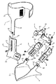
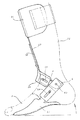
図1、2に開示するように、この考案による足先支持具1は、上部支持体2と、下部支持体3と、湾曲した両接続部材4と、複数の弾性部材Sと、両連結部材5と、足先支持部6とによってなる。
As disclosed in FIGS. 1 and 2, a foot support 1 according to the present invention includes an
上部支持体2は、脛を覆う湾曲部21と、湾曲部21の略中央の位置から下方に延伸し、且つ末端にナット22を設けたスライドガイド部23とを有する。
The
下部支持体3は、内側に凹溝31を形成したプレート状のスライドガイド座32と、スライドガイド座32の略中央の位置に縦方向に形成する第1スライド溝33と、スライドガイド座32の下端両側に一体に形成され、且つ第2スライド溝34を形成した円弧状のカバー部35とを具え、凹溝31には上支持体2のスライドガイド部23を挿入してネジで位置決めする。
The lower support 3 includes a plate-shaped
接続部材4は、一端に第2スライド溝34に接続するためのネジ孔41を穿設し、他端は中心の位置にネジ孔41を穿設して偏移当止部43として、ネジ孔41にネジを相通させて、下支持体3の第2スライド溝34に螺着する。
The
複数の弾性部材Sは、加重によって圧縮し、荷重から開放されると本来の状態に復帰する構造を具え、偏移当止部43の下端両側に封入される。
The plurality of elastic members S are compressed by a load and have a structure that returns to their original state when released from the load, and are enclosed on both sides of the lower end of the
連結部材5は、上端側に収納溝51を形成し、且つ収納溝51の略中央の位置にネジ孔53を穿設するとともに、下端側に挿入溝52を形成し、且つ中央の位置に長手方向に沿って第3スライド溝54を形成し、収納溝51に接続部材4の偏移当止部43を挿入する。
The connecting
足先支持部6は、足先の形状に合わせて湾曲させた支持部61を有し、両側面の重心を支える位置から上方にスライド部63が延伸して一体に形成され、スライド部63の上端にナット62を嵌着する。スライド部63は連結部材5の挿入溝52に挿入して、ネジで接続する。
The foot support portion 6 includes a
上述する部材によって構成する足先支持具7は、使用者の足先を支持して補助的な作用を与えることができ、使用者にとって便利な歩行の動作を支持する効果が発生する(図3に開示する構造参照) The foot support 7 composed of the above-described members can support the user's foot and can provide an auxiliary action, thereby producing an effect of supporting a walking operation convenient for the user (FIG. 3). (See the structure disclosed in)
図3、図3A、図4、図4Aに開示するように、使用者が足先Pを上に上げる動作を行う場合、踵P1が上方に上がって人体の重心が前に傾く。かかる前傾の動作は、下部支持体3に対して時計の逆周り方向の圧迫を与える。このため偏移当止部43の左側に位置する弾性部材2が圧力を受けて縮小する図3A参照)。使用者が足先Pを踏み出すために下方にさせる場合、人体の重心が後方にあるため、脹脛P2が後方に傾斜した状態になる。係る後方に傾斜する動作は下部支持体3に対して時計回りと逆方向の方向の圧迫が生じる。この場合偏移当止部の右側に位置する弾性部材Sが圧力を受けて縮小する(図4A参照)。このため、弾性部材Sが伸縮する弾性(圧力を受けて縮小し、圧力が開放されると復帰する特性)によって所定の角度(90°±15°)の偏差と、位置のずれが発生し、使用者が違和感なく、自然に歩行することができる。即ち、足が地面を離れる場合、支持具は弾性部材Sが圧縮されること無く90°の角度を呈する。よって、足が地面を離れる場合に地面と摩擦することなく自然に歩行することができる。
As disclosed in FIG. 3, FIG. 3A, FIG. 4, and FIG. 4A, when the user performs an action of raising the foot tip P, the heel P1 rises upward and the center of gravity of the human body tilts forward. Such forward tilting operation applies pressure in the counterclockwise direction to the lower support 3. For this reason, the
また、この考案においては面ファスナーなどを用いることによって、上部支持体2を脹脛の部分に固定するか、もしくは下部支持体3を踵に近い位置に拘束して位置決めすることによって、使用者に簡易で便利な取り付けを提供することができる。更に、この考案による足先支持部のそれぞれの部材の内側に、軟性のパッドを設けることによって、脹脛や踵などの部分に対して違和感を与えることがなくなる。
In this device, the
更に、この考案による足先支持具は、構成部材にスライド溝を形成して接続位置を自在に調節できるように構成する。よって、使用者の足のサイズに合わせて支持具のサイズを調整できるため、従来の技術に見られるように使用者の足のサイズに合わせて作成する必要がない。 Furthermore, the foot support according to the present invention is configured so that the connecting position can be freely adjusted by forming a slide groove in the component member. Therefore, since the size of the support can be adjusted in accordance with the size of the user's foot, it is not necessary to create the support tool in accordance with the size of the user's foot as seen in the prior art.
以上はこの考案の好ましい実施例であって、この考案の実施の範囲を限定するものではない。よって、当業者のなし得る修正、もしくは変更であって、この考案の精神の下においてなされ、この考案に対して均等の効果を有するものは、いずれも本考案の実用新案登録請求の範囲に属するものとする。 The above is a preferred embodiment of the present invention, and does not limit the scope of implementation of the present invention. Therefore, any modifications or changes that can be made by those skilled in the art, which are made within the spirit of the present invention and have an equivalent effect on the present invention, belong to the scope of the utility model registration claim of the present invention. Shall.
2 上部支持体
21 湾曲部
22 ナット
23 スライドガイド部
3 下部支持体
31 凹溝
32 スライドガイド座
33 第1スライド溝
34 第2スライド溝
35 カバー部
4 接続部材
41 ネジ孔
42 ネジ孔
43 偏移当止部
5 連結部材
51 収納溝
52 挿入溝
53 ネジ孔
54 第3スライド溝
6 足先支持部
61 支持部
62 ナット
63 スライド部
7 足先支持具
S 弾性部材
P 足先
P1 踵
P2 脹脛
2
Claims (4)
該上部支持体は、脛を覆う湾曲部と、該湾曲部の略中央の位置から下方に延伸し、且つ末端にナットを設けたスライドガイド部とを有し、
下部支持体は、内側に凹溝を形成したプレート状のスライドガイド座と、該スライドガイド座の略中央の位置に縦方向に形成する第1スライド溝と、該スライドガイド座の下端両側に一体に形成され、且つ第2スライド溝を形成した円弧状のカバー部とを具え、該凹溝には該上支持体のスライドガイド部を挿入してネジで位置決めしてなり、
該接続部材は、一端に第2スライド溝に接続するためのネジ孔を穿設し、他端は中心の位置にネジ孔を穿設して偏移当止部とし、
該複数の弾性部材は、該偏移当止部の下端両側に封入され、
該連結部材は、上端側に収納溝を形成し、且つ該収納溝の略中央の位置にネジ孔を穿設するとともに、下端側に挿入溝を形成し、且つ中央の位置に長手方向に沿って第3スライド溝を形成し、該収納溝に該接続部材の該偏移当止部を挿入してなり、
足先支持部は、足先の形状に合わせて湾曲させた支持部を有し、両側面の重心を支える位置から上方にスライド部が延伸して一体に形成され、該スライド部の上端にナットを嵌着し、該スライド部は該連結部材の該挿入溝に挿入して、ネジで接続することを特徴とする足先支持具。 A foot support comprising an upper support, a lower support, curved connecting members, a plurality of elastic members, both connecting members, and a foot support;
The upper support has a curved portion that covers the shin, and a slide guide portion that extends downward from a substantially central position of the curved portion and that is provided with a nut at the end.
The lower support is integrated with a plate-shaped slide guide seat having a concave groove formed therein, a first slide groove formed in a vertical direction at a substantially central position of the slide guide seat, and both sides of the lower end of the slide guide seat. And an arcuate cover portion having a second slide groove formed therein, the slide guide portion of the upper support is inserted into the concave groove and positioned with a screw,
The connection member has a screw hole for connecting to the second slide groove at one end, and a screw hole at the center of the other end to form a shift stopper.
The plurality of elastic members are sealed on both sides of the lower end of the shift stopper,
The connecting member has a storage groove on the upper end side, and a screw hole is formed at a substantially central position of the storage groove, an insertion groove is formed on the lower end side, and the central position is along the longitudinal direction. Forming a third slide groove, and inserting the shift stop portion of the connection member into the storage groove,
The foot support portion has a support portion that is curved in accordance with the shape of the foot tip, and the slide portion extends upward from a position that supports the center of gravity of both side surfaces, and a nut is formed at the upper end of the slide portion. , And the slide part is inserted into the insertion groove of the connecting member and connected with a screw.
Priority Applications (1)
| Application Number | Priority Date | Filing Date | Title |
|---|---|---|---|
| JP2005010871U JP3119913U (en) | 2005-12-22 | 2005-12-22 | Foot support |
Applications Claiming Priority (1)
| Application Number | Priority Date | Filing Date | Title |
|---|---|---|---|
| JP2005010871U JP3119913U (en) | 2005-12-22 | 2005-12-22 | Foot support |
Publications (1)
| Publication Number | Publication Date |
|---|---|
| JP3119913U true JP3119913U (en) | 2006-03-16 |
Family
ID=43470109
Family Applications (1)
| Application Number | Title | Priority Date | Filing Date |
|---|---|---|---|
| JP2005010871U Expired - Fee Related JP3119913U (en) | 2005-12-22 | 2005-12-22 | Foot support |
Country Status (1)
| Country | Link |
|---|---|
| JP (1) | JP3119913U (en) |
Cited By (13)
| Publication number | Priority date | Publication date | Assignee | Title |
|---|---|---|---|---|
| JPH04137327U (en) * | 1991-06-18 | 1992-12-21 | 株式会社エンプラス | surface light source device |
| JPH0569731U (en) * | 1992-02-19 | 1993-09-21 | シャープ株式会社 | LCD lighting device |
| JP2565462Y2 (en) | 1992-05-29 | 1998-03-18 | タイホー工業株式会社 | Line light source and edge light type backlight using the same |
| JP2605408Y2 (en) | 1993-12-22 | 2000-07-17 | 松下電工株式会社 | Flat lighting |
| JP3192796B2 (en) | 1993-02-05 | 2001-07-30 | 三洋電機株式会社 | Liquid crystal display |
| JP3322592B2 (en) | 1997-02-27 | 2002-09-09 | 三洋電機株式会社 | Liquid crystal display device and manufacturing method thereof |
| JP3355204B2 (en) | 1992-08-18 | 2002-12-09 | 株式会社きもと | Lamp reflector |
| JP3413995B2 (en) | 1994-10-26 | 2003-06-09 | ソニー株式会社 | Liquid crystal display |
| JP2010063632A (en) * | 2008-09-10 | 2010-03-25 | Japan Labour Health & Welfare Organization | Standing-up and upright position holding applicator for paraplegic person |
| JP2012090758A (en) * | 2010-10-27 | 2012-05-17 | Toyota Motor Corp | Leg orthosis |
| WO2015040758A1 (en) * | 2013-09-18 | 2015-03-26 | クリエイド合同会社 | Body weight support device |
| JP5807888B1 (en) * | 2015-01-28 | 2015-11-10 | 有限会社出水義肢装具製作所 | Prosthetic joint joint joint |
| KR20240044135A (en) * | 2022-09-28 | 2024-04-04 | 한국과학기술연구원 | Motion assist apparatus |
-
2005
- 2005-12-22 JP JP2005010871U patent/JP3119913U/en not_active Expired - Fee Related
Cited By (15)
| Publication number | Priority date | Publication date | Assignee | Title |
|---|---|---|---|---|
| JPH04137327U (en) * | 1991-06-18 | 1992-12-21 | 株式会社エンプラス | surface light source device |
| JPH0569731U (en) * | 1992-02-19 | 1993-09-21 | シャープ株式会社 | LCD lighting device |
| JP2565462Y2 (en) | 1992-05-29 | 1998-03-18 | タイホー工業株式会社 | Line light source and edge light type backlight using the same |
| JP3355204B2 (en) | 1992-08-18 | 2002-12-09 | 株式会社きもと | Lamp reflector |
| JP3192796B2 (en) | 1993-02-05 | 2001-07-30 | 三洋電機株式会社 | Liquid crystal display |
| JP2605408Y2 (en) | 1993-12-22 | 2000-07-17 | 松下電工株式会社 | Flat lighting |
| JP3413995B2 (en) | 1994-10-26 | 2003-06-09 | ソニー株式会社 | Liquid crystal display |
| JP3322592B2 (en) | 1997-02-27 | 2002-09-09 | 三洋電機株式会社 | Liquid crystal display device and manufacturing method thereof |
| JP2010063632A (en) * | 2008-09-10 | 2010-03-25 | Japan Labour Health & Welfare Organization | Standing-up and upright position holding applicator for paraplegic person |
| JP2012090758A (en) * | 2010-10-27 | 2012-05-17 | Toyota Motor Corp | Leg orthosis |
| WO2015040758A1 (en) * | 2013-09-18 | 2015-03-26 | クリエイド合同会社 | Body weight support device |
| JP2015058083A (en) * | 2013-09-18 | 2015-03-30 | クリエイド合同会社 | Body weight supporting device |
| JP5807888B1 (en) * | 2015-01-28 | 2015-11-10 | 有限会社出水義肢装具製作所 | Prosthetic joint joint joint |
| WO2016121019A1 (en) * | 2015-01-28 | 2016-08-04 | 有限会社出水義肢装具製作所 | Articulating joint for limb braces |
| KR20240044135A (en) * | 2022-09-28 | 2024-04-04 | 한국과학기술연구원 | Motion assist apparatus |
Similar Documents
| Publication | Publication Date | Title |
|---|---|---|
| US9414954B2 (en) | Posture improving garment | |
| CN100522112C (en) | Ambulating knee joint | |
| JP5189714B2 (en) | Set of knee orthosis, outer leg side joint and inner leg side joint | |
| US11285356B2 (en) | Portable lower limb therapy device | |
| US20140364783A1 (en) | Dynamic load bearing shock absorbing exoskeletal knee brace | |
| US20180153638A1 (en) | Body support device for surgery | |
| US11452660B2 (en) | Apparatus and method of training human brain and body to walk using modular an exoskeleton | |
| JP2021184793A (en) | Insole and shoe including the same | |
| US20200383815A1 (en) | Ankle-foot orthosis with extension control | |
| ME00543B (en) | Device for preventing or relieving pain in the lower back | |
| CN221512345U (en) | Foot exoskeleton with adjustable torsion | |
| US10688334B2 (en) | Stretch exercise system | |
| US20070027420A1 (en) | Structure of ankle protection kit | |
| JPS61170454A (en) | Stabilizing splint | |
| TWI854929B (en) | Assist device for knee joint | |
| JP3236061U (en) | Multi-functional massage tool | |
| CN216294274U (en) | Orthopedics arthroscopic surgery auxiliary device | |
| KR200403122Y1 (en) | movable sporting equipment | |
| TWM256156U (en) | Improved structure for fixing and buffering the knee joint | |
| JP2008507304A (en) | Prosthetic knee joint | |
| KR101828359B1 (en) | Health Assistance Apparatus For Relaxing Foot | |
| JPS5995043A (en) | Mount tool for exercising joint motion function | |
| Taiar et al. | CAD and mechanical development of a new kind of hemiplegics orthosis | |
| TWM458997U (en) | Knee exerciser | |
| JP2020005877A (en) | Bowleg/pigeon-toed gait improving cushion |
Legal Events
| Date | Code | Title | Description |
|---|---|---|---|
| R150 | Certificate of patent or registration of utility model |
Free format text: JAPANESE INTERMEDIATE CODE: R150 |
|
| LAPS | Cancellation because of no payment of annual fees |