JP3107059U - Yarn winding device - Google Patents
Yarn winding device Download PDFInfo
- Publication number
- JP3107059U JP3107059U JP2004005261U JP2004005261U JP3107059U JP 3107059 U JP3107059 U JP 3107059U JP 2004005261 U JP2004005261 U JP 2004005261U JP 2004005261 U JP2004005261 U JP 2004005261U JP 3107059 U JP3107059 U JP 3107059U
- Authority
- JP
- Japan
- Prior art keywords
- spool
- rotating body
- thread
- commercial
- base
- Prior art date
- Legal status (The legal status is an assumption and is not a legal conclusion. Google has not performed a legal analysis and makes no representation as to the accuracy of the status listed.)
- Expired - Fee Related
Links
Images


Landscapes
- Filamentary Materials, Packages, And Safety Devices Therefor (AREA)
Abstract
【課題】糸が巻かれた市販スプールから、作業者が移動せずに、又、道具を移動させずに、既作成の糸と略同じ長さの糸を卓上にて取り出すこと。
【解決手段】当市販スプールから糸を巻き取る回転体を持ち、回転体に既作成の糸と略同じ長さの糸を巻き取る卓上型装置を考案した。
【選択図】 図1An object of the present invention is to take out, on a table, a thread having a length substantially the same as an already created thread from a commercial spool wound with a thread without moving an operator or moving a tool.
A desktop device has been devised that has a rotating body that winds a thread from this commercially available spool, and winds a thread of approximately the same length as a previously created thread on the rotating body.
[Selection] Figure 1
Description
本考案は、考案者を同一人とする実用新案登録第3101980号の考案を部分的に取り出し改良したものである。 The present invention is a partial extraction and improvement of the utility model registration No. 3101980 with the same creator.
本考案は、糸の巻かれた市販スプールから糸を取り出し、既作成の糸と略同じ長さだけ巻き取る装置に関するものである。 The present invention relates to an apparatus for taking out a yarn from a commercially available spool on which the yarn is wound, and winding up the yarn by a length substantially the same as that of an already produced yarn.
従来、糸の巻かれた市販スプールから、その糸を既作成の糸と略同じ長さだけ取り出す際、短い長さなら短いスケールを使って移動せずに糸を測りながら当市販スプールから取り出すことができるが、長い長さの場合、人が糸の端を持ちスケールに沿って移動するか、或いは、長さの既知の棒状のものに合わせて棒を移動させながら当市販スプールから糸を取り出していた。 Conventionally, when taking out the thread from a commercial spool wound with a thread approximately the same length as the existing thread, if the length is short, remove it from this commercial spool while measuring the thread without moving using a short scale. However, if the length is long, a person can hold the end of the thread and move it along the scale, or remove the thread from this commercial spool while moving the bar according to a rod with a known length. It was.
糸の巻かれた市販スプールから、既作成の糸と略同じ長さだけ糸を取り出す際に、スケールに沿った人の移動、又は、スケール代わりの棒の移動と云った煩雑、或いは、部屋の中での作業は不可能とも感ずる作業を伴う問題点があった。 When removing a thread from a commercial spool wound with a thread by the same length as an already created thread, the movement of a person along the scale or the movement of a bar instead of the scale, or the room There was a problem with work that felt that work inside was impossible.
本考案は、当市販スプールから、既作成の糸と略同じ長さだけ糸を取り出す際、作業者が移動せず、道具も移動させないで卓上で糸を取り出すことを目的としている。 An object of the present invention is to take out the yarn on the table without moving the operator and moving the tool when the yarn is taken out from the commercially available spool by substantially the same length as that of the existing yarn.
糸の巻かれた市販スプールから、既作成の糸と略同じ長さだけ巻き取る卓上型装置を提供する。 Provided is a tabletop device that winds up a length approximately the same as an already created thread from a spool on which a thread is wound.
この装置は、平面上に置いた市販スプールから糸を引っ張って取り出す際の市販スプールの移動を制限するレールを有する構造のスプール台、及び、記録スペースと色分けした外周を有しスムーズに回転する回転体を回転方向が取り付け面に平行になるように取り付けた台からなる。 This device has a spool base with a rail that restricts the movement of the commercial spool when pulling the thread from the commercial spool placed on a flat surface, and a rotation that smoothly rotates with a color space and a recording space. It consists of a base on which the body is mounted such that the direction of rotation is parallel to the mounting surface.
スプール台と台は蝶番などで接続し二つ折りにでき、或いは、二つ折りにしたスプール台又は台を箱形にして回転体を箱の中に収納できるようにすることも可能である。 The spool base and the base can be connected to each other by a hinge or the like, or can be folded in two, or the spool base or the base folded in half can be box-shaped so that the rotating body can be stored in the box.
既作成の糸を回転体に巻き取り、巻き取った糸の端の位置にマークを記録し、その近傍に巻き取りに要する回転体の回転数、回転方向、他の情報を記録して、以後、この記録に従って回転体に糸を巻き取ることによって必要な長さの糸を得ることができる。 Wind the already-created thread around the rotating body, record the mark at the end of the wound thread, record the rotational speed, rotational direction, and other information of the rotating body required for winding in the vicinity. According to this recording, a yarn having a required length can be obtained by winding the yarn around the rotating body.
回転体外周の色分けによって、回転体の回転方向を上記記録時と逆に回転させて使用する場合、同色であることによって、逆回転に対する記録位置を、改めて記録せずとも知ることができる。 When the rotating body is used in a color-coded manner on the outer periphery of the rotating body, the rotating position of the rotating body is rotated in the reverse direction to that during recording, the recording position with respect to the reverse rotation can be known without recording again.
市販スプールを囲むレールによって、中心部の形状が種種ある市販スプールに対応してその移動の制限が可能となる為、市販スプールの中心部の形状を選ぶことなく使用することができる。 Since the rail surrounding the commercial spool can limit the movement of the central portion corresponding to various commercial spools, it can be used without selecting the shape of the central portion of the commercial spool.
回転体の回転方向を台と平行にしたので高さ方向にかさばらない為、蝶番などで接続したスプール台と台とを二つ折りにすることができ、良好な収納性が得られると同時に室内卓上で作業することができる。 Since the rotation direction of the rotating body is parallel to the base, it is not bulky in the height direction, so the spool base connected to the hinge and the base can be folded in half, providing good storage and at the same time an indoor tabletop Can work with.
台を箱形にし、回転体をその箱に収納する事によってより良好な収納性が得られる。 A better storage property can be obtained by making the base into a box shape and storing the rotating body in the box.
考案を実施するための最良の形態を実施例に基づき図面を参照して説明する。
図2において、回転体1の全面にわたって記録スペース5を設ける。The best mode for carrying out the invention will be described based on an embodiment with reference to the drawings.
In FIG. 2, a recording space 5 is provided over the entire surface of the rotating body 1.
記録スペース5の表面は、記録を使用者が書き換えながら使用する為、且つ、確定した記録は長い間保持しておく必要がある為、簡単に消えない方法がとれる材質とする。 The surface of the recording space 5 is made of a material that allows the user to rewrite the record and keep the confirmed record for a long time.
回転体1の外周に、記録がどこにあるかの目安とするため、糸の長さの誤差が許容できる範囲の回転量で外周を等分し、色を塗り分けて色分け6を設ける。 In order to provide an indication of where the recording is located on the outer periphery of the rotator 1, the outer periphery is equally divided by the amount of rotation within a range in which an error in the length of the yarn can be allowed, and the colors 6 are separately provided.
色分け6は、回転体1を市販スプールの形状によって反対方向に回転させて作業する事を考慮して、回転体の直径を対称に同色とする。 In the color coding 6, considering that the rotating body 1 is rotated in the opposite direction depending on the shape of the commercial spool, the diameters of the rotating bodies are symmetrically the same color.
回転体1は回転中に糸がスムーズに巻かれるよう鍔が付いた円筒形とし、回転させるに便利なよう可倒又は取り外し可能なハンドル7を取り付ける。 The rotating body 1 has a cylindrical shape with a hook so that the thread can be wound smoothly during rotation, and a handle 7 that can be tilted or detached is attached for convenient rotation.
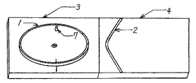
図1、及び、図3において、回転体1がスムーズに回転し、回転体1の回転方向が回転体1を取り付けた台3の表面と平行になる構造とする。 1 and 3, the rotating body 1 rotates smoothly, and the rotating direction of the rotating body 1 is parallel to the surface of the table 3 to which the rotating body 1 is attached.
台3、及び、回転体1の適当な位置に、回転体1の回転開始位置を表示する。 The rotation start position of the rotating body 1 is displayed at an appropriate position of the table 3 and the rotating body 1.
スプール台4には、作業中に、市販スプールが移動しすぎて装置から飛び出さないよう、市販スプールを囲むレール2を取り付ける。 A
レール2の、市販スプールを囲む形状は円形、楕円形、多角形、それらの組み合わせ、又は、それらの一部、等、とし、且つ、市販スプールがスムーズに回転する形状とする。 The shape of the
レール2の高さは、市販スプールが作業中に装置から飛び出さず、且つ、糸がスムーズに出てくる高さ、形状とする。 The height of the
スプール台4の市販スプールとの接触面は、作業中、市販スプールがスムーズに回転する構造とする。 The contact surface of the
台3とスプール台4の接続は蝶番等でなされ、二つ折りできる構造とする。 The
台3に回転体1の回転数をカウントするカウンターを取り付けても良い。 A counter that counts the number of rotations of the rotating body 1 may be attached to the table 3.
台3を箱形にして回転体1をこの箱の中に収納する構造としても良い。 It is good also as a structure which makes the stand 3 a box shape and accommodates the rotary body 1 in this box.
スプール台4の市販スプールの接触面は、図1の如く回転体1の設置面と平行又は同じ高さとする。 The contact surface of the
スプール台4は図3の如く回転体1の設置面と角度を付けた坂面として、作業中、市販スプールが滑り落ちる構造としても良い。 As shown in FIG. 3, the
図3の構造の場合、レール2の向きは図1の場合と逆、即ち、市販スプールが坂面から滑り落ちるのを防ぐ方向とする。 In the case of the structure of FIG. 3, the direction of the
釣りの仕掛け作りにおいて、使用者が、今後作ろうとして現在持っている既作成の仕掛けを回転体1に巻き取り、その時の回転体1の回転数を記憶する。 In making a fishing device, a user winds up an already created device that he / she currently wants to make in the future, and stores the rotation speed of the rotating device 1 at that time.
巻き取った既作成の仕掛けの端が位置する記録スペース5の部分にマークし、記憶した回転数、回転方向、使用する竿の種類、仕掛けの長さ、等、必要な情報をマークの近傍に記録する。 Mark the part of the recording space 5 where the end of the already-prepared device that has been wound is located, and store the necessary information such as the stored number of rotations, direction of rotation, type of hook used, device length, etc. Record.
回転体1を逆に回転させながら、既作成の仕掛けを元に戻す。 While the rotating body 1 is rotated in the reverse direction, the previously created device is returned to the original state.
今後、使用するハリスが巻かれた市販スプールをスプール台に置き、ちちわ結び、サルカン取り付け、等、必要な作業を施し、作業を施したハリスの端を回転体1の鍔に止め、書き込んだ記録に従って、回転体1を必要回転数だけ回転させ、更に記録したマークの位置までハリスを巻き取り、切ることによって既作成の仕掛けと略同じ長さの仕掛けを得ることができる。 In the future, put the commercial spool on which the Harris to be used was wound on the spool stand, perform the necessary work such as tying the knot, attaching the sarkan, etc. According to the recording, the rotary body 1 is rotated by the necessary number of rotations, and Harris is wound up to the position of the recorded mark and cut, whereby a device having a length substantially the same as that of the already prepared device can be obtained.
上記で得たハリスに、ゴム管通し、目印取り付け、針結び、又は、枝ス取り付け、サルカン取り付け、等、必要な作業を施し、回転体1を逆に回転させながら手持ちの仕掛け巻きに巻き取る。 The Harris obtained above is subjected to necessary operations such as threading a rubber tube, attaching a mark, attaching a knot, attaching a branch, attaching a sarkan, etc., and winding it around a hand-held device while rotating the rotating body 1 in reverse. .
同様の作業を繰り返すことによって、既作成の仕掛けと略同じ長さの同じ仕掛けを幾つも作ることができる。 By repeating the same operation, it is possible to make several devices with the same length as the devices already created.
更に、作ろうとする別の種類の既作成の仕掛けを用意して、既述の作業手順で作業をすることによって別の種類の新たな仕掛けを作ることができる。 Furthermore, another type of new device to be created can be prepared, and another type of new device can be created by working in accordance with the above-described work procedure.
本考案が携帯型としても使用できるため、釣行に携帯することによって釣行先での仕掛け作りが可能である。 Since the present invention can also be used as a portable type, it is possible to make a device at a fishing destination by carrying it in a fishing line.
本考案は釣りの分野を意識したものであるが、糸状のものを扱う分野、例えば手芸の分野、或いは、装置をより大型化強固化して、線材、電線等を扱う線材の分野にも利用できる。 Although the present invention is conscious of the field of fishing, it can be used in the field of handling wire-like objects, for example, the field of handicrafts, or the field of wire rods handling wire rods, electric wires, etc. .
1 回転体
2 レール
3 台
4 スプール台
5 記録スペース
6 色分け
7 ハンドル1
Claims (1)
Priority Applications (1)
| Application Number | Priority Date | Filing Date | Title |
|---|---|---|---|
| JP2004005261U JP3107059U (en) | 2004-08-05 | 2004-08-05 | Yarn winding device |
Applications Claiming Priority (1)
| Application Number | Priority Date | Filing Date | Title |
|---|---|---|---|
| JP2004005261U JP3107059U (en) | 2004-08-05 | 2004-08-05 | Yarn winding device |
Publications (1)
| Publication Number | Publication Date |
|---|---|
| JP3107059U true JP3107059U (en) | 2005-01-27 |
Family
ID=43269794
Family Applications (1)
| Application Number | Title | Priority Date | Filing Date |
|---|---|---|---|
| JP2004005261U Expired - Fee Related JP3107059U (en) | 2004-08-05 | 2004-08-05 | Yarn winding device |
Country Status (1)
| Country | Link |
|---|---|
| JP (1) | JP3107059U (en) |
-
2004
- 2004-08-05 JP JP2004005261U patent/JP3107059U/en not_active Expired - Fee Related
Similar Documents
| Publication | Publication Date | Title |
|---|---|---|
| US4062608A (en) | Telephone handset cord storage apparatus | |
| US6254029B1 (en) | Weed trimmer line rewinder device | |
| JP6606682B2 (en) | Long wire reel | |
| JP2014236728A (en) | Fishing reel equipped with fishhook holding means | |
| US4143832A (en) | Thread dispenser | |
| CN208835597U (en) | Wire bundling device and automatic binding equipment | |
| US5865394A (en) | Self contained bobbin winder | |
| CN211644128U (en) | A loose cable storage device | |
| JP3101980U (en) | String winding device | |
| JP5019244B1 (en) | Tape holder | |
| JP3041647U (en) | Wrapped body | |
| CN223149986U (en) | Data line reason line board | |
| JP4142535B2 (en) | Hose winder | |
| JP2510722Y2 (en) | Portable wire cutting tool | |
| CN221703217U (en) | Knot-preventing building site wire falling device | |
| CN219839307U (en) | Network cable storage structure for network machine room | |
| JP2788232B2 (en) | Reel box | |
| CN217732260U (en) | Winding device | |
| JP3238348U (en) | Embroidery thread | |
| CN219885311U (en) | Cable storage reel | |
| CN219567194U (en) | Building construction measuring line drop | |
| CN220351384U (en) | Wire spool convenient to fix | |
| CN216548965U (en) | Wire rewinding mechanism for signal transmission connecting wire | |
| KR200475910Y1 (en) | Portable electric wire reel | |
| JPH0455005Y2 (en) |
Legal Events
| Date | Code | Title | Description |
|---|---|---|---|
| R150 | Certificate of patent or registration of utility model |
Free format text: JAPANESE INTERMEDIATE CODE: R150 |
|
| LAPS | Cancellation because of no payment of annual fees |