JP2025504545A - An electrical therapy device that combines electrical stimulation and manual therapy - Google Patents
An electrical therapy device that combines electrical stimulation and manual therapy Download PDFInfo
- Publication number
- JP2025504545A JP2025504545A JP2024544482A JP2024544482A JP2025504545A JP 2025504545 A JP2025504545 A JP 2025504545A JP 2024544482 A JP2024544482 A JP 2024544482A JP 2024544482 A JP2024544482 A JP 2024544482A JP 2025504545 A JP2025504545 A JP 2025504545A
- Authority
- JP
- Japan
- Prior art keywords
- sinusoidal voltage
- electrodes
- active electrodes
- frequency
- configuration
- Prior art date
- Legal status (The legal status is an assumption and is not a legal conclusion. Google has not performed a legal analysis and makes no representation as to the accuracy of the status listed.)
- Pending
Links
Images




Classifications
-
- A—HUMAN NECESSITIES
- A61—MEDICAL OR VETERINARY SCIENCE; HYGIENE
- A61N—ELECTROTHERAPY; MAGNETOTHERAPY; RADIATION THERAPY; ULTRASOUND THERAPY
- A61N1/00—Electrotherapy; Circuits therefor
- A61N1/02—Details
- A61N1/04—Electrodes
- A61N1/0404—Electrodes for external use
-
- A—HUMAN NECESSITIES
- A61—MEDICAL OR VETERINARY SCIENCE; HYGIENE
- A61N—ELECTROTHERAPY; MAGNETOTHERAPY; RADIATION THERAPY; ULTRASOUND THERAPY
- A61N1/00—Electrotherapy; Circuits therefor
- A61N1/02—Details
- A61N1/04—Electrodes
- A61N1/0404—Electrodes for external use
- A61N1/0408—Use-related aspects
- A61N1/0456—Specially adapted for transcutaneous electrical nerve stimulation [TENS]
-
- A—HUMAN NECESSITIES
- A61—MEDICAL OR VETERINARY SCIENCE; HYGIENE
- A61N—ELECTROTHERAPY; MAGNETOTHERAPY; RADIATION THERAPY; ULTRASOUND THERAPY
- A61N1/00—Electrotherapy; Circuits therefor
- A61N1/02—Details
- A61N1/04—Electrodes
- A61N1/0404—Electrodes for external use
- A61N1/0472—Structure-related aspects
- A61N1/0476—Array electrodes (including any electrode arrangement with more than one electrode for at least one of the polarities)
-
- A—HUMAN NECESSITIES
- A61—MEDICAL OR VETERINARY SCIENCE; HYGIENE
- A61N—ELECTROTHERAPY; MAGNETOTHERAPY; RADIATION THERAPY; ULTRASOUND THERAPY
- A61N1/00—Electrotherapy; Circuits therefor
- A61N1/02—Details
- A61N1/04—Electrodes
- A61N1/06—Electrodes for high-frequency therapy
-
- A—HUMAN NECESSITIES
- A61—MEDICAL OR VETERINARY SCIENCE; HYGIENE
- A61N—ELECTROTHERAPY; MAGNETOTHERAPY; RADIATION THERAPY; ULTRASOUND THERAPY
- A61N1/00—Electrotherapy; Circuits therefor
- A61N1/18—Applying electric currents by contact electrodes
- A61N1/32—Applying electric currents by contact electrodes alternating or intermittent currents
- A61N1/36—Applying electric currents by contact electrodes alternating or intermittent currents for stimulation
- A61N1/36014—External stimulators, e.g. with patch electrodes
- A61N1/3603—Control systems
- A61N1/36034—Control systems specified by the stimulation parameters
-
- A—HUMAN NECESSITIES
- A61—MEDICAL OR VETERINARY SCIENCE; HYGIENE
- A61N—ELECTROTHERAPY; MAGNETOTHERAPY; RADIATION THERAPY; ULTRASOUND THERAPY
- A61N1/00—Electrotherapy; Circuits therefor
- A61N1/40—Applying electric fields by inductive or capacitive coupling ; Applying radio-frequency signals
- A61N1/403—Applying electric fields by inductive or capacitive coupling ; Applying radio-frequency signals for thermotherapy, e.g. hyperthermia
-
- H—ELECTRICITY
- H02—GENERATION; CONVERSION OR DISTRIBUTION OF ELECTRIC POWER
- H02M—APPARATUS FOR CONVERSION BETWEEN AC AND AC, BETWEEN AC AND DC, OR BETWEEN DC AND DC, AND FOR USE WITH MAINS OR SIMILAR POWER SUPPLY SYSTEMS; CONVERSION OF DC OR AC INPUT POWER INTO SURGE OUTPUT POWER; CONTROL OR REGULATION THEREOF
- H02M7/00—Conversion of AC power input into DC power output; Conversion of DC power input into AC power output
- H02M7/42—Conversion of DC power input into AC power output without possibility of reversal
- H02M7/44—Conversion of DC power input into AC power output without possibility of reversal by static converters
Landscapes
- Health & Medical Sciences (AREA)
- Life Sciences & Earth Sciences (AREA)
- Animal Behavior & Ethology (AREA)
- Nuclear Medicine, Radiotherapy & Molecular Imaging (AREA)
- Radiology & Medical Imaging (AREA)
- Biomedical Technology (AREA)
- Engineering & Computer Science (AREA)
- General Health & Medical Sciences (AREA)
- Public Health (AREA)
- Veterinary Medicine (AREA)
- Biophysics (AREA)
- Heart & Thoracic Surgery (AREA)
- Electrotherapy Devices (AREA)
Abstract

【解決手段】電気治療装置は、Nが2または3であるN個の電極(212、222、240)と、2つの正弦波電圧発生器(210、220)と、正弦波電圧発生器に関する2つの変圧器(211、221)と、制御ユニット、とを備える。正弦波電圧発生器(210、220)は、変圧器(211、221)によって絶縁される。制御ユニットは、電気治療装置が交互に第1の構成および第2の構成を取るように電気治療装置を制御する。第1の構成は、Nは、2であり、電極(212、222)は、アクティブ電極であり、正弦波電圧発生器(210、220)は、直列に配置され、電気治療装置は、リターン電極(240)を含まず、アクティブ電極(212、222)は、それぞれ正弦波電圧発生器(210、220)に接続され、最も近い2つのアクティブ電極(212、222)間で電流が流れるように、アクティブ電極(212、222)で異なる電位を発生する直列構成である。第2の構成は、Nは、3であり、2つの電極(212、220)は、それぞれ2つの正弦波電圧発生器(210、220)に接続されたアクティブ電極であり、1つの電極(240)は、グランドを形成するためのリターン電極であって、正弦波電圧発生器(210、220)に接続されており、正弦波電圧発生器(210、220)は、並列に配置され、最も近い2つのアクティブ電極(212、222)間で、および/または、アクティブ電極(212、222)とリターン電極(240)との間で電流が流れるように、アクティブ電極(210、222)で異なる電位を発生する並列構成である。
【選択図】図1
The electrotherapy device comprises N electrodes (212, 222, 240), where N is 2 or 3, two sinusoidal voltage generators (210, 220), two transformers (211, 221) associated with the sinusoidal voltage generators, and a control unit. The sinusoidal voltage generators (210, 220) are isolated by the transformers (211, 221). The control unit controls the electrotherapy device to alternately assume a first configuration and a second configuration. In the first configuration, N is 2, the electrodes (212, 222) are active electrodes, the sinusoidal voltage generators (210, 220) are arranged in series, the electrotherapy device does not include a return electrode (240), and the active electrodes (212, 222) are each connected to the sinusoidal voltage generators (210, 220) in a series configuration that generates different electrical potentials at the active electrodes (212, 222) such that current flows between the two nearest active electrodes (212, 222). In the second configuration, N is 3, two electrodes (212, 220) are active electrodes connected to two sinusoidal voltage generators (210, 220) respectively, and one electrode (240) is a return electrode for forming a ground and is connected to the sinusoidal voltage generators (210, 220), and the sinusoidal voltage generators (210, 220) are arranged in parallel, generating different potentials at the active electrodes (210, 222) such that current flows between the two nearest active electrodes (212, 222) and/or between the active electrodes (212, 222) and the return electrode (240).
[Selected Figure] Figure 1
Description
本発明は、治療用または美容用の電子機器に関する。本発明は、特に、いわゆる電気治療分野、特に、ジアテルミーおよび/または導電性による治療への応用を見出すであろう。 The present invention relates to medical or cosmetic electronic devices. The invention will find application in particular in the field of so-called electrotherapy, in particular in diathermy and/or electroconductive therapy.
電気療法は、治療目的で電気を使用する非危険性の非侵襲的技術である。この技術は、痛みを和らげたり、筋繊維を強化したり、生体組織の治癒を促進したりすることが認められている。低周波(1Hz~150Hz)は表面的な神経刺激作用、中周波(1kHz~1kHz)は深部神経刺激作用、高周波(100kHz~1.2MHz)は表面的または深部選択的なジアテルサーマル作用と治癒促進作用がある。低周波(LF)と中周波(MF)は一般に電気刺激と呼ばれ、高周波(HF)は高周波と呼ばれる。 Electrotherapy is a non-hazardous, non-invasive technique that uses electricity for therapeutic purposes. It has been shown to relieve pain, strengthen muscle fibers, and promote healing of living tissue. Low frequency (1Hz-150Hz) has a superficial nerve stimulation effect, medium frequency (1kHz-1kHz) has a deep nerve stimulation effect, and high frequency (100kHz-1.2MHz) has a superficial or deep selective diathermal effect and promotes healing. Low frequency (LF) and medium frequency (MF) are commonly referred to as electrical stimulation, and high frequency (HF) is called radiofrequency.
これらのさまざまなタイプの電気治療電流は、皮膚に接触して電極の役割を果たす2枚のプレートまたは導電性エレメントの間を循環する。施術者は、さまざまなタイプの電流を使用することができる。 These different types of electrical therapy currents circulate between two plates or conductive elements that contact the skin and act as electrodes. The practitioner can use different types of electrical currents.
温熱は、キネシテラピーにおいて長年使用されてきた治療法であり、表面温熱剤と深部温熱剤の2つに分類される。深部温熱療法のモダリティには、長波および短波の治療用または美容用ジアテルミー、超音波、接触型高周波があり、後者は100kHz~1.2MHzの高周波電流とも呼ばれる。この種の深部温熱療法はジアテルミーと呼ばれる。ジアテルミーは、生体組織と接触している2つの電極の間で、身体の損傷部分の細胞組織に熱を発生させ、この2つの電極の間で身体に電流の循環が起こるようにする。 Heat is a treatment that has been used for many years in kinesitherapy and is divided into two categories: superficial and deep heat. Deep heat modalities include long and short wave therapeutic or cosmetic diathermy, ultrasound, and contact radio frequency, also called radio frequency currents between 100 kHz and 1.2 MHz. This type of deep heat therapy is called diathermy. Diathermy works by generating heat in the tissue of the injured area of the body between two electrodes that are in contact with the tissue, allowing a current to circulate through the body between the two electrodes.
例えば特許ES287964に開示されているように、電流伝導型ジアテルミー装置にはアクティブ電極とリターン電極と が含まれる。 For example, as disclosed in patent ES287964, a current conduction diathermy device includes an active electrode and a return electrode.
組織自体の電気インピーダンスのため、電流は組織内を循環し、ジュール効果によって組織の温度上昇を引き起こす。この加熱は、電流の強度の増加に関連しており、顕著である。 Due to the tissue's own electrical impedance, the current circulates in the tissue, causing an increase in its temperature due to the Joule effect. This heating is significant and is related to the increase in the intensity of the current.
組織の導電率は高周波電流の関数として変化する。電圧が高いほど、組織の導電性は高くなり、治癒が加速される。 Tissue conductivity changes as a function of the RF current. The higher the voltage, the more conductive the tissue and the faster the healing.
複数の電極がある場合、それらは単一の高周波電圧発生器に接続され、治療においてジアテルミー効果と組織の治癒を同時に促進する。従って、これら2つの効果は組み合わされ、切り離すことはできない。 When there are multiple electrodes, they are connected to a single high-frequency voltage generator, promoting both the diathermy effect and tissue healing in the treatment simultaneously. Thus, these two effects are combined and cannot be separated.
US5776173A1という文献が知られている。この文献は電気治療用の干渉刺激装置を提案している。この装置は、それぞれ周波数を持つ出力信号を発生する2つの発振器を備え、出力信号はミキサーを通過する前にいくつかの成分を通過する。ミキサーは出力信号を結合し、次にバイポーラまたはクアドリポーラ療法に従って出力モダリティを選択するスイッチに印加される。この装置は、一対の電極に単一の混合低周波信号を印加する。 The document US5776173A1 is known. This document proposes an interferometric stimulation device for electrical therapy. The device comprises two oscillators each generating an output signal with a frequency, which passes through several components before passing through a mixer. The mixer combines the output signals, which are then applied to a switch that selects the output modality according to bipolar or quadripolar therapy. The device applies a single mixed low-frequency signal to a pair of electrodes.
US2010/0152817A1という文献が知られている。この文献は、様々な適用モードに従って、一対の電極が連続的または交互に神経を電気刺激するためのネットワークシミュレータを提案している。このシミュレータは、信号が周期的に連続する一対の電極に順次送信され、それぞれの一対の電極が異なる瞬間に対応する信号を受信するような性質の電気パルスを生成する。このシミュレーターは、電気パルスの様々な応用により、より長い、またはより高い振幅のシミュレーションパルスを生成することを提案する。このシミュレータは、各対の電極に1つの同じ信号を供給する。 The document US2010/0152817A1 is known. This document proposes a network simulator for electrical stimulation of nerves by pairs of electrodes, successively or alternately, according to various application modes. The simulator generates electrical pulses of such a nature that a signal is periodically sent sequentially to successive pairs of electrodes, each pair of electrodes receiving a corresponding signal at a different moment. The simulator proposes to generate simulated pulses of longer length or higher amplitude by various applications of the electrical pulses. The simulator supplies one and the same signal to each pair of electrodes.
また、US2003/0181960A1という文献も知られている。この文献は、電極によって第1の信号と第2の信号から投与され、戻り電極によって回収される治療信号を生成する電気治療装置を提案している。この装置では、多様な治療を行うことはできない。この装置は低周波で作動する。 Also known is the document US 2003/0181960 A1. This document proposes an electrotherapy device that generates a therapeutic signal administered by an electrode from a first signal and a second signal and retrieved by a return electrode. This device does not allow for a multimodal treatment. The device operates at low frequencies.
従って、特に、治療を受けるユーザーにとってよりリスクが少なく、より効果的で、治療を行う施術者にとっては簡素化された、最適化された治療を可能にする解決策を提案する必要がある。 There is therefore a need to propose solutions that allow for an optimized treatment that is, in particular, less risky and more effective for the user receiving the treatment and simplified for the practitioner carrying out the treatment.
本発明の他の目的、特徴および利点は、以下の説明および添付図面を検討することにより明らかになるであろう。他の利点を組み込むことができることは理解される。 Other objects, features and advantages of the present invention will become apparent from a consideration of the following description and accompanying drawings. It is understood that other advantages may be incorporated.
この目的を達成するために、一実施の形態によれば、電気治療装置が与えられる。この装置は、
‐Nが2または3であるN個の電極(212、222、240)と、
‐2つの正弦波電圧発生器(210、220)と、
‐前記正弦波電圧発生器に関する2つの変圧器(211、221)と、
‐制御ユニット、とを備え、
前記正弦波電圧発生器(210、220)は、前記変圧器(211、221)によって絶縁され、
前記制御ユニットは、前記電気治療装置が交互に第1の構成および第2の構成を取るように前記電気治療装置を制御し、
・前記第1の構成は、
Nは、2であり、
電極(212、222)は、アクティブ電極であり、
前記正弦波電圧発生器(210、220)は、直列に配置され、
前記電気治療装置は、リターン電極(240)を含まず、
アクティブ電極(212、222)は、ぞれぞれ前記正弦波電圧発生器(210、220)に接続される直列構成であり、
最も近い2つのアクティブ電極(212、222)間で電流が流れるように、前記アクティブ電極(212、222)で異なる電位を発生し、
・前記第2の構成は、
Nは、3であり、
2つの電極(212、220)は、それぞれ前記2つの前記正弦波電圧発生器(210、220)に接続されたアクティブ電極であり、
1つの電極(240)は、グランドを形成するためのリターン電極であって、前記正弦波電圧発生器(210、220)に接続されており、
前記正弦波電圧発生器(210、220)は、並列に配置され、
最も近い2つのアクティブ電極(212、222)間で、および/または、前記アクティブ電極(212、222)とリターン電極(240)との間で電流が流れるように、前記アクティブ電極(210、222)で異なる電位を発生する並列構成である。
To this end, according to one embodiment, an electrotherapy device is provided, the device comprising:
- N electrodes (212, 222, 240), where N is 2 or 3;
- two sinusoidal voltage generators (210, 220),
- two transformers (211, 221) for said sinusoidal voltage generator,
a control unit,
The sinusoidal voltage generators (210, 220) are insulated by the transformers (211, 221);
the control unit controls the electrotherapy device to alternately assume a first configuration and a second configuration;
The first configuration is
N is 2;
the electrodes (212, 222) are active electrodes;
The sinusoidal voltage generators (210, 220) are arranged in series,
the electrotherapy device does not include a return electrode (240);
the active electrodes (212, 222) are in a series configuration connected to the sinusoidal voltage generators (210, 220), respectively;
generating different electrical potentials at the two closest active electrodes (212, 222) such that a current flows between said two closest active electrodes (212, 222);
The second configuration is
N is 3;
Two electrodes (212, 220) are active electrodes connected to the two sinusoidal voltage generators (210, 220), respectively;
One electrode (240) is a return electrode for forming a ground and is connected to the sinusoidal voltage generator (210, 220);
The sinusoidal voltage generators (210, 220) are arranged in parallel,
A parallel configuration generates different electrical potentials at the active electrodes (210, 222) such that current flows between the two nearest active electrodes (212, 222) and/or between the active electrodes (212, 222) and a return electrode (240).
従って、本発明により、ユーザーの身体に複数の電極を通して複数の信号を印加することが可能となる。これはバイチャネル装置である。施術者は、2つの電圧発生器を並列化または直列化することにより、ジアテルミーおよび/または伝導性を提供する完全な治療を実施することができる。2つの絶縁されたジェネレーターの存在により、電気回路上で隔離されたユーザーは、危険なく使用することができる。さらに、アクティブ電極間で分流された電流を作用させてユーザーの治療を行う可能性があるため、治療ゾーンの表面積を増大させ、多重治療を提供することが可能となる。従来は、アクティブ電極とリターン電極またはニュートラル電極の間の電流に集中するために、アクティブ電極間で分流する電流を減らそうとしていたので、この選択は非常に驚くべきことである。 The invention therefore makes it possible to apply several signals through several electrodes to the user's body. It is a bi-channel device. By paralleling or serializing the two voltage generators, the practitioner can carry out a complete treatment providing diathermy and/or conductivity. The presence of two insulated generators allows the user to be isolated on the electrical circuit without danger. Furthermore, the possibility of treating the user by acting on the current shunted between the active electrodes makes it possible to increase the surface area of the treatment zone and provide multiple treatments. This choice is very surprising, since in the past, one would have tried to reduce the current shunted between the active electrodes in order to concentrate the current between the active and the return or neutral electrodes.
有利なことに、各アクティブ電極は電圧発生器に接続され、各電圧発生器によって生成される第1の信号または第2の信号をそれぞれ受信する。好ましくは、第1の信号と第2の信号とは異なる。 Advantageously, each active electrode is connected to a voltage generator and receives a first signal or a second signal, respectively, generated by the respective voltage generator. Preferably, the first signal and the second signal are different.
別の態様は、上記の装置を動作させるための方法に関する。この方法は、以下の動作モードを含む。
‐装置の第1の構成に関する第1の動作モードであり、以下の特徴を持つ。Nは2である。電極はアクティブ電極であり、それぞれが電圧発生器に接続される。2つの電圧発生器は直列に接続される。電流が2つのアクティブ電極間を循環する。
‐装置の第2の構成に関する第2の動作モードであり、以下の特徴を持つ。Nは3である。電極のうちの2つの電極はアクティブ電極であり、それぞれが電圧発生器に接続される。電極のうちの1つはリターン電極である。2つの電圧発生器は並列に接続される。電流が、最も近いアクティブ電極間、および、アクティブ電極とリターン電極との間を循環する。
Another aspect relates to a method for operating the above apparatus, the method including the following modes of operation.
- a first operating mode for a first configuration of the device, characterized in that: N is 2; the electrodes are active electrodes, each connected to a voltage generator; the two voltage generators are connected in series; a current circulates between the two active electrodes;
- A second operating mode for a second configuration of the device, characterized in that: N is 3; Two of the electrodes are active electrodes, each connected to a voltage generator; One of the electrodes is a return electrode; The two voltage generators are connected in parallel; Current circulates between the nearest active electrodes and between the active and return electrodes.
本発明の目的、趣旨、特徴および利点は、以下の添付図面によって示されるその一実施の形態の詳細な説明からより明確に明らかになるであろう。
本発明の実施の形態の詳細な検討を行う前に、任意選択的に、互いの代替として、または互いと組み合わせて使用することができる特徴を以下に示す。 Before proceeding to a detailed discussion of embodiments of the present invention, the following features are presented, which may be used, optionally, as alternatives to each other or in combination with each other.
一実施例によれば、各電圧発生器は、高周波電圧、優先的には100kHz以上10MHz以下の高周波電圧を発生する。 According to one embodiment, each voltage generator generates a high frequency voltage, preferentially a high frequency voltage between 100 kHz and 10 MHz.
一実施例によれば、アクティブ電極は移動可能である。 According to one embodiment, the active electrode is movable.
一実施例によれば、アクティブ電極は容量性または抵抗性または多極性である。 According to one embodiment, the active electrodes are capacitive or resistive or multipolar.
一実施例によれば、各電圧発生器は、電圧発生器の出力パラメータを測定する測定部を備える。 According to one embodiment, each voltage generator includes a measurement unit that measures an output parameter of the voltage generator.
一実施例によれば、各電圧発生器は、電圧発生器の出力電流および/または周波数および/または減衰を制御する制御モジュールを備える。 According to one embodiment, each voltage generator comprises a control module that controls the output current and/or frequency and/or attenuation of the voltage generator.
制御モジュールは、例えば、マイクロコントローラまたはマイクロプロセッサまたはプログラマブル論理回路(CPLD Complex Programmable Logic Device)またはフィールドプログラマブルゲートアレイ(Field Programmable Gate Array FPGA)またはアナログ回路である。 The control module is, for example, a microcontroller or a microprocessor or a programmable logic device (CPLD: Complex Programmable Logic Device) or a field programmable gate array (FPGA: Field Programmable Gate Array) or an analog circuit.
一実施例によれば、測定部は、制御モジュールと通信し、制御に必要なデータを制御モジュールに供給する。有利なことに、電圧発生器は、測定部によって測定されたインピーダンスに応じてその出力を制御することができる。 According to one embodiment, the measurement unit communicates with the control module and provides the control module with the data required for control. Advantageously, the voltage generator can control its output depending on the impedance measured by the measurement unit.
一実施例によれば、本発明による装置は、電圧発生器の同期または非同期を制御する同期部を備える。 According to one embodiment, the device according to the present invention comprises a synchronization unit that controls the synchronization or asynchronous operation of the voltage generator.
一実施例によれば、この装置は、電圧発生器の出力とアクティブ電極との間に配置されたスイッチを含まない。 According to one embodiment, the device does not include a switch disposed between the output of the voltage generator and the active electrode.
一実施例によれば、装置は、電圧発生器の出力とアクティブ電極との間に配置された混合部を含まない。 According to one embodiment, the device does not include a mixing section disposed between the output of the voltage generator and the active electrode.
一実施例によれば、本発明による方法は、制御モジュールによって2つの電圧発生器の位相調整または位相解除を制御するステップと、2つのアクティブ電極間に循環する電流を発生させるように、同期化または非同期化信号を送信することによって、同期部によって2つの電圧発生器の同期化を制御するステップとを含んでいる。 According to one embodiment, the method according to the invention includes the steps of controlling the phasing or dephasing of the two voltage generators by a control module, and controlling the synchronization of the two voltage generators by a synchronization unit by sending a synchronization or desynchronization signal to generate a circulating current between the two active electrodes.
本発明は、ユーザーの身体のジアテルミーおよび/または導電による治療を行うことができる電気治療装置に関する。 The present invention relates to an electrotherapy device capable of performing diathermy and/or conductive treatment of a user's body.
有利には、本発明による電気治療装置は、ジアテルミーもしくは導電性、またはジアテルミーと導電性との組み合わせによってユーザーの身体の治療を可能とする。 Advantageously, the electrotherapy device according to the present invention allows for the treatment of the user's body by diathermy or electrical conductivity, or a combination of diathermy and electrical conductivity.
有利には、装置の電圧発生器を直列化(直列にするともいう)または並列化(並列にするともいう)することにより、様々な治療が行われる。 Advantageously, various treatments are performed by serializing (also called serializing) or parallelizing (also called parallelizing) the voltage generators of the device.
本発明による電気治療装置は、複数の電極、すなわち2個または3個の電極を備える。ある可能性によれば、電極の数は2または3、またはより一般的には偶数または奇数である。 The electrotherapy device according to the invention comprises a plurality of electrodes, i.e. two or three electrodes. According to one possibility, the number of electrodes is two or three, or more generally an even or odd number.
本発明による電気治療装置はまた、2つの正弦波電圧発生器210、220を備える。
好ましくは、装置の正弦波電圧発生器210、220の数は、電極の数、より詳細にはアクティブ電極212、222の数に応じて定義される。1つの可能性として、アクティブ電極の数が偶数である場合、正弦波電圧発生器の数はこの電極数に等しい。
The electrotherapy device according to the present invention also comprises two sinusoidal voltage generators 210,220.
Preferably, the number of
本装置は、2つのチャネルを含む。各チャネルは、電圧発生器210、220から供給される。1つの可能性として、各電圧発生器210、220は、発生器の信号の出力に対応する伝送チャネルと呼ばれる少なくとも1つのチャネルを含む。電極は、アクティブ電極212、222である。電極は、ユーザー10の身体に電流を供給する。好ましくは、2つのアクティブ電極212、222は、異なるチャネルに接続される。有利には、各アクティブ電極212、222は、電圧発生器、より正確には電圧発生器の伝送路に接続される。構成によっては、装置はまた、リターン電極またはニュートラル電極240、すなわち、アクティブ電極212、222によって伝送される。すなわち、ユーザー10の身体の一部を通過した電流を受ける電極を構成することができる。1つの可能性として、各電圧発生器210、220は、ユーザー10の身体の一部を通過した電流を受信する入力に対応する、いわゆる受信チャネルを構成する。リターン電極240は、ユーザー10の身体における電気回路の閉鎖を提供する。すなわちリターン電極240は、アースを形成する。リターン電極240は、優先的には固定されているが、治療によっては移動可能であってもよい。固定式とは、治療中、施術者によってリターン電極が動かされないことを意味する。この場合、電極は、保持手段によってユーザーに固定され続けることができる。可動とは、施術中に電極が施術者によって動かされ得ることを意味する。
The device includes two channels. Each channel is supplied by a
電極212、222、240は、ユーザー10の身体に適用されるように構成されている。有利には、電極212、222、240は、ユーザー10の身体に接触している。
The
アクティブ電極212、222は、容量性、抵抗性または多極性とすることができる。多極性とは、アクティブ電極212、222が、同時に容量性極と抵抗性極のような2つの導電性極を含むことを意味する。
The
アクティブ電極212、222は、治療の要求に応じて固定または可動とすることができる。
The
また、本発明による電気治療装置は、装置が第1の構成と第2の構成とを交互にとるように構成された制御ユニットを備える。制御ユニットは、例えば、マイクロコントローラまたはマイクロプロセッサまたはプログラマブル論理回路(CPLD Complex Programmable Logic Device)またはフィールドプログラマブルゲートアレイ(Field Programmable Gate Array FPGA)またはアナログ回路である。 The electrotherapy device according to the invention also comprises a control unit configured to cause the device to alternate between a first configuration and a second configuration. The control unit is, for example, a microcontroller or a microprocessor or a programmable logic device (CPLD Complex Programmable Logic Device) or a field programmable gate array (FPGA) or an analog circuit.
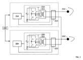
第1の構成の装置は、N個の電極(アクティブ電極212、222)を備える。Nは2に等しい。この装置は、リターン電極240を備えない。従って、各電極212、222は、電圧発生器210、220に接続されている。2つの電圧発生器210、220は、直列に配置される。この構成を図1と図2に示す。
The device in the first configuration has N electrodes (
第2の構成の装置は、N個の電極を備える。Nは3に等しい。そのうちの2つの電極はアクティブ電極212、222であり、残りの1つの電極はリターン電極240である。従って、各アクティブ電極212、222は、電圧発生器210、220に接続されている。リターン電極240は、2つの電圧発生器210、220の共通点に接続されている。好ましくは、2つの電圧発生器210、220の共通点は、各電圧発生器の各受信チャネルに接続される。2つの電圧発生器210、220は、並列に配置される。この構成を図3、図4、図5に示す。
The device in the second configuration comprises N electrodes, where N is equal to 3. Two of the electrodes are
好ましい実施の形態によれば、電圧発生器210、220は絶縁されている。電圧発生器210、220は、ガルバニックに絶縁されている。図に示す一実施の形態によれば、電圧発生器210、220の絶縁は、各電圧発生器210、220の出力に配置された変圧器211、221によって実現される。装置の電気回路から絶縁された状態にあることから、絶縁された電圧発生器は、電流を受けるユーザーに大きな安全性を提供する。
According to a preferred embodiment, the
変圧器211、222は、有利には、電圧発生器210、220によって送信される信号が同相または逆相であることの要求に応じて、同相または逆相、特に逆相になるように構成される。
The
このようにして、本発明によれば、装置は、リターン電極240を使用することも使用しないことも可能にする。本発明による装置は、アクティブ電極212、222間、優先的には2つのアクティブ電極212、222間を循環する分流電流を使用する。これらの分流電流は、従来技術の装置では低減されるか、あるいは防止されることさえあった。
Thus, according to the invention, the device allows for the use or non-use of a
有利なことに、各アクティブ電極212、222はそれぞれ、優先的にそれぞれのチャネルによって正弦波電圧発生器210、220に接続されている。好ましくは、この装置は、電圧発生器210の第1の信号を2つのアクティブ電極に、または第2の電圧発生器210の第2の信号を2つのアクティブ電極に伝達するためのスイッチを含んでいない。有利には、装置は、第1の発生器の第1の信号と第2の発生器の第2の信号とを結合するための混合部を含まない。
Advantageously, each
好ましくは、各発電器によって生成された信号は、アクティブ電極に印加される。 Preferably, the signal generated by each generator is applied to an active electrode.
本発明による装置は、最も近い2つの電極212、222、240の間で電流の伝送ができるように、各電極212、222で異なる電位を生成するように構成される。
The device according to the present invention is configured to generate a different electrical potential at each
本発明によれば、全てのアクティブ電極212、222におけるニュートラル点または浮動共通点は、構成に応じて、ユーザー10の身体に適用されるリターン電極240に接続されるか、または接続されない。
In accordance with the present invention, the neutral or floating common points of all
本装置を用いる方法は、第1の構成によれば、アクティブ電極212、222間に複合電圧110を発生させ、および/または、第2の構成によれば、アクティブ電極212、222とユーザー10の身体に印加されるリターン電極240との間に単純電圧120、121を発生させる。
A method of using the device, in a first configuration, generates a
好ましい実施の形態では、本装置は電気治療、より正確にはジアテルミーを目的とする。この目的のために、各電圧発生器210、220は高周波電圧を発生する。高周波電圧は、好ましくは100kHz以上10MHz以下である。
In a preferred embodiment, the device is intended for electrical therapy, more precisely diathermy. For this purpose, each
有利には、この装置は、各電圧発生器210、220に対して、測定部213、223を備える。測定部213、223は、絶縁された電圧発生器210、220から出力される信号のパラメータを測定する。
Advantageously, the device comprises a measuring
好ましくは、装置は、各電圧発生器210、220に対して、制御モジュール214、224を備える。制御モジュール214、224は、絶縁電圧発生器210、220からの信号出力を制御する。好ましくは、制御モジュール214、224は、例えば電流の周波数および/または電圧発生器の減衰を調節する。一例として、制御モジュール214、224は、マイクロコントローラまたはマイクロプロセッサまたはプログラマブル論理回路(CPLD Complex Programmable Logic Device)またはフィールドプログラマブルゲートアレイ(Field Programmable Gate Array FPGA)またはアナログ回路である。
Preferably, the device comprises a
有利には、測定部213、223は、制御に必要なデータを制御モジュール214、224に供給するように、制御モジュール214、224と通信する。
Advantageously, the
好ましくは、装置は、電圧発生器210、220を制御するように有利に配置された同期部230を備える。同期部230は、各電圧発生器210、220の同期入力に配置される。同期部230は、電圧発生器210、220の同期化または非同期化、従って伝送される信号の同期化または非同期化を可能にする。同期とは、伝送される信号が同じ角周波数および/または同じ周波数および/または同じ周期を有することを意味する。同期部230は、信号の同期化または非同期化を制御するように、各電圧発生器に対して例えば同期化信号を生成する。図4および図5に示されるように、2つの電圧発生器210、220が同期しているとき、電流は各アクティブ電極212、222とニュートラル電極240の間を循環する。一方、2つの電圧発生器210、220が非同期であるとき、電流は2つのアクティブ電極212、220の間も循環し、それは分流電流110となる。信号の同期または非同期の制御は、2つのアクティブ電極間の分流電流の形成と維持に関与する。
Preferably, the device comprises a
有利なことに、電圧発生器210、220は独立しており、特に装置によって見られるインピーダンスに応じて出力信号を調整することができる。本発明による装置は、有利には、マルチ出力装置、すなわち、別個の出力信号を発生する電圧発生器に接続された2つのアクティブ電極を含む。
Advantageously, the
有利には、各電圧発生器210、220に対して送信される信号は正弦波である。好ましくは、
V=Vamp×sin(wt+Φ)
である。Vamp=正弦波信号の振幅、w=角周波数、Φ=度単位の位相差、である。
Advantageously, the signal sent to each
V = Vamp × sin(wt + Φ)
where Vamp = amplitude of the sinusoidal signal, w = angular frequency, and Φ = phase difference in degrees.
好ましい実施の形態によれば、装置は、各電圧発生器210、220の信号の位相調整または位相解除を可能にする。従って、出力電圧は波の位相差に応じて変化する。電圧発生器210、220の信号が同相の場合、2つのアクティブ電極212、222間の電圧は出力電圧Voutの2倍となる(V110=2×Vout)。ただし、Vout=電圧発生器の出力電圧。電圧発生器210、220の信号が180°位相がずれている場合、出力電圧はゼロとなり、Vamp=0Vとなる。ただし、Vamp=出力正弦波信号の振幅。
According to a preferred embodiment, the device allows phasing or dephasing of the signals of each
第1の構成における第1の実施の形態によれば、本発明による装置は図1に示されている。 According to a first embodiment in a first configuration, the device according to the invention is shown in FIG.
この第1の実施の形態の第1の構成によれば、Nは2に等しい。2つのアクティブ電極212、222は、それぞれ電圧発生器210、220に接続されている。この第1の構成による装置は、リターン電極を含まない。この第1の構成では、電圧発生器210、220は直列に配置される。
According to a first configuration of this first embodiment, N is equal to 2. Two
電圧発生器210、220は、有利には、各電圧発生器210、220の出力にそれぞれ配置された変圧器211、222によって絶縁されている。
The
変圧器211、222は、有利には、信号が同相または逆相であることの要求に応じて、同相または逆相、特に逆相となるように構成されている。
この第1の実施の形態による装置は、各電圧発生器210、220の出力に配置された2つの測定部213、223を備える。各測定部213、223は、各電圧発生器210、220のそれぞれの制御モジュール214、224に接続されている。
The device according to this first embodiment comprises two measuring
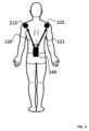
この第1の構成による本実施の形態では、リターン電極240がない場合、循環する電流は、図3に示されるように、ユーザー10の身体に印加される2つのアクティブ電極212、222間の分流電流110である。
In this first configuration of the present embodiment, in the absence of a
この最初の構成では、信号は複合的であると言われる。V110=V120+V121である。ここで、V110は、2つのアクティブ電極212、222の間を循環する電流110の電圧である。V120は、アクティブ電極212と、図示されないニュートラル電極240と、の間を循環する電流120の電圧である。V121は、アクティブ電極222と、図示されないニュートラル電極240と、の間を循環する電流121の電圧である。
In this first configuration, the signal is said to be complex: V110 = V120 + V121 , where V110 is the voltage of the current 110 circulating between the two
この第1の構成では、2つの絶縁された電圧発生器210、220を直列に配置することにより、絶縁の破壊効果、すなわち硬い生体組織(骨、靭帯など)の透磁率の上昇を求め、そこに電流を循環させるために、電圧を公称値の2倍まで上昇させることができる。
In this first configuration, by placing two
この最初の構成により、直列化されたジアテルミーによる治療が可能になる。この構成により、2つの電圧発生器210、220を直列に配置し、ジアテルミーを発生する信号を印加することが可能になる。この治療は、2つのアクティブ電極によって実行され、リターン電極は、ユーザーに印加されないので、フローティングと言われる。この配置は、電流が生体組織の伝導性を最大にし、従って治癒を促進する。一方、加熱を最小にするために、電圧を増加させ、その強度を増加させない。その目的は、最大800Vrmsの電圧で前記組織の細胞代謝を促進することである。
This first configuration allows a treatment with serialized diathermy. It allows two
この第1の構成では、電圧発生器210、220は、送信される信号が位相がずれて同期するように構成される。
In this first configuration, the
本発明のこの第1の実施の形態によれば、装置は、代替的に、図3に示される第2の構成をとってもよい。 According to this first embodiment of the invention, the device may alternatively have a second configuration as shown in FIG. 3.
この第2の実施の形態の構成によれば、Nは3に等しい。2つのアクティブ電極212、222は、それぞれ電圧発生器210、220に接続されている。この第2の構成による装置は、リターン電極240を備える。リターン電極240は、有利には、電圧発生器210、220の共通点に接続される。この第2の構成では、電圧発生器210、220は、並列に配置されている。
According to the configuration of this second embodiment, N is equal to 3. Two
この実施の形態において、リターン電極240からなるこの第2の構成によれば、電流は、アクティブ電極212、222とリターン電極240との間を循環するが、有利には、図4に示されるように、2つのアクティブ電極212、222の間も循環する。
In this embodiment, with this second configuration of the
この第2の構成では、信号は電流120、121と単純であると言われる。各電圧発生器210、220は、異なるインピーダンスを供給する。電極はユーザー10の身体に適用され、2つのアクティブ電極212、222の間にインピーダンスが存在する。2つのアクティブ電極212、222間には、電圧V110が印加される。電圧V110は、2つのアクティブ電極212、222の近接に応じて、また、上記に示した信号の位相差に応じて変化する。
In this second configuration, the signals are said to be simply
この第2の構成では、2つの電圧発生器210、220を並列に置くことにより、強度をその公称値の2倍まで増加させて、通過した組織の加熱、すなわちジアテルミー作用を求めることができる。アクティブ電極212、222を互いに近づけたり遠ざけたりすると、電力が変化する。
In this second configuration, by placing the two
この第2の構成により、ジアテルミーと導電性を組み合わせた治療を行うことが可能になる。この構成により、2つの電圧発生器210、220を並列に配置することが可能になり、その結果、ジアテルミーと導電性を発生する信号を印加することが可能になる。この第2の構成では、3つの電極間に分配された3つの電流セグメントを形成するために、リターン電極240がユーザー10の身体上に配置される。3つの電流セグメント110、120、121の合計は、電気治療装置によって供給される電力に相当する。さらに、この構成は、電圧ではなく強度を増加させ、最大4アンペアの強度で通過する生体組織の加熱(ジアテルミー)に有利である。
This second configuration allows for a combined diathermy and electrical conductivity treatment. This configuration allows for two
図4と図5では、2つのアクティブ電極212、222は、周波数および特性が異なる正弦波電流を流す。これらは、電流120が循環する電気セグメントおよび電流121が循環する電気セグメントを経由して、リターン電極240に向かって収束する。本発明により、ユーザー10の身体上の3つの電極212、222、240の3つの電気セグメントによって、バイフェーズ装置によって放出される電力を分配することが可能になる。各電極212、222、240の間には電気セグメントがあり、当業者はこれら3つの電極212、222、240の間で電力を分配する方法を定義することができる。本装置は、信号の減衰によって同期または非同期をとるように構成される。
4 and 5, the two
図4では、信号は同期しており、同位相であってもよく、同位相でなくてもよい。分流電流はない。 In Figure 4, the signals are synchronous and may or may not be in phase. There are no shunt currents.
図5では、信号は非同期であり、同位相であってもよく、同位相でなくてもよい。分流電流はある。 In Figure 5, the signals are asynchronous and may or may not be in phase. There is a shunt current.
図6に示す第2の実施の形態によれば、Nは2に等しい。2つのアクティブ電極212、222は、それぞれ電圧発生器210、220に接続されている。この第2の構成による装置は、リターン電極を含まない。この第1の構成では、電圧発生器210、220は、直列に配置されている。アクティブ電極212、222は、有利には、図6および図7に示されるように、同時にまたは交互にアクティブおよびニュートラルとなるように構成され、単一の電極212、222上で電流の入出力の循環を提供する。
According to a second embodiment shown in FIG. 6, N is equal to 2. Two
一実施の形態によれば、アクティブ電極はスマート電極であってもよい。これらの電極は、施術者の動きをリアルタイムで知ることができる慣性ユニットを備える。施術者は、より良い効果を得るために、使用中の施術を修正することができる。また、使用されている電極の種類も認識される。制御モジュール214, 224は、検出された電極の種類に応じて出力を調整する。
According to one embodiment, the active electrodes may be smart electrodes. These electrodes are equipped with an inertial unit that allows the practitioner's movements to be known in real time. The practitioner can modify the treatment in use to obtain a better effect. Also, the type of electrode being used is known. The
この装置は、一例として、300kHz以上1MHz以下の範囲の周波数で、最大単純電圧400Vrms、最大単純電流1.2Arms、出力150W、および300kHz以上1MHz以下の範囲の周波数で、最大複合電圧800Vrms、最大単純電流2.4Arms、出力300Wに有利に設計されている。 As an example, this device is advantageously designed for a maximum simple voltage of 400 Vrms, a maximum simple current of 1.2 Arms, and an output of 150 W at frequencies in the range of 300 kHz to 1 MHz, and a maximum combined voltage of 800 Vrms, a maximum simple current of 2.4 Arms, and an output of 300 W at frequencies in the range of 300 kHz to 1 MHz.
このように本発明は、高周波電流の電圧および強度を変化させ、異なる強度および/または電圧および/または周波数での作業を可能とし、さまざまなタイプの電極を組み合わせたり、組み合わせなかったりすることを可能とする。 The invention thus allows the voltage and intensity of the high frequency current to be varied, allowing operation at different intensities and/or voltages and/or frequencies, and allowing the use of various types of electrodes in combination or not.
1つの可能性として、電圧発生器210、220は、低周波、中周波、高周波信号を変調することによって、多周波電圧を発生するように動作することができる。最高周波数の電圧発生器は、最低周波数の電圧発生器によって振幅変調される。電力は不平衡である。各発電器は、その電極と関連する電極に対応する電力を供給する。電力は、各発電機の振幅と位相差に応じて調整される。
As one possibility, the
この可能性によれば、電気治療装置は、第1の周波数を有する第1の電圧を発生し、第1の接続端子と第2の接続端子とを備える第1の電圧発生器と、第1の周波数よりも高い第2の周波数を有する第2の電圧を発生し、第3の接続端子と第4の接続端子とを備える第2の電圧発生器と、送信チャネルと、受信チャネルとを備える。第1の接続端子と第3の接続端子とは、前記送信チャネルに接続される。第2の接続端子と第4の接続端子とは、前記受信チャネルに接続される。 According to this possibility, the electrotherapy device includes a first voltage generator generating a first voltage having a first frequency and including a first connection terminal and a second connection terminal, a second voltage generator generating a second voltage having a second frequency higher than the first frequency and including a third connection terminal and a fourth connection terminal, a transmission channel, and a reception channel. The first connection terminal and the third connection terminal are connected to the transmission channel. The second connection terminal and the fourth connection terminal are connected to the reception channel.
この可能性により、同じ1つの送信チャネルと、同じ1つの受信チャネルと、によって、2つの異なる周波数の2つの電圧を印加することができる。 This possibility allows two voltages of two different frequencies to be applied using the same transmit channel and the same receive channel.
より詳細には、電気治療装置は、第1の電圧発生器を制御して第1の周波数で第1の電圧を発生させ、第2の電圧発生器を制御して第2の周波数で第2の電圧を同時に発生させる制御ユニットを備える。 More specifically, the electrotherapy device includes a control unit that controls a first voltage generator to generate a first voltage at a first frequency and controls a second voltage generator to simultaneously generate a second voltage at a second frequency.
有利には、制御ユニットは、第3の周波数で変調された第1の周波数の正弦波電圧と、第4の周波数で変調された第2の周波数の正弦波電圧と、を関連付けた信号を伝送路に生成する。信号は、第1の生成モジュールの電圧と、第2の生成モジュールの電圧と、の和である。 Advantageously, the control unit generates a signal on the transmission line relating a sinusoidal voltage of the first frequency modulated with a third frequency and a sinusoidal voltage of the second frequency modulated with a fourth frequency. The signal is the sum of the voltage of the first generating module and the voltage of the second generating module.
別の態様は、電気治療装置を動作させるための方法に関する。この方法は、以下のステップを含む。
a.第1の電圧発生器により、第1の周波数で第1の電圧を発生させるステップ。
b.第2の電圧発生器により、第1の周波数よりも高い第2の周波数で第2の電圧を発生させるステップ。
ステップaおよびbは同時に実行される。このように、2つの電圧発生器は同時に動作する。
Another aspect relates to a method for operating an electrotherapy device, the method including the following steps.
generating a first voltage at a first frequency with a first voltage generator;
b) generating, with a second voltage generator, a second voltage at a second frequency higher than the first frequency;
Steps a and b are performed simultaneously. Thus, the two voltage generators operate simultaneously.
一実施例によれば、第1の電圧発生器は、正弦波電圧を発生する。 According to one embodiment, the first voltage generator generates a sinusoidal voltage.
一実施例によれば、第1の周波数は1kHz以上10kHz以下の第1の周波数間隔にある。 According to one embodiment, the first frequency is in a first frequency interval between 1 kHz and 10 kHz.
一実施例によれば、第1の電圧発生器は、第3の周波数によって変調された第1の周波数の正弦波電圧を発生する。 According to one embodiment, the first voltage generator generates a sinusoidal voltage at a first frequency modulated by a third frequency.
一実施例によれば、第3の周波数は、1Hz以上150Hz以下の第3の周波数間隔にある。 According to one embodiment, the third frequency is in a third frequency interval of 1 Hz to 150 Hz.
一例によれば、第3の周波数は正弦波電圧である。 According to one example, the third frequency is a sinusoidal voltage.
本装置は、低周波信号(電気刺激)を変調するために中周波正弦波信号を作成し、高周波正弦波信号(ジアテルミー)と組み合わせる。従って、本装置は、単一のチャネル内で、電気刺激および高周波発生ジアテルミーの利点を組み合わせることができる。本装置は、身体の自然治癒機構を刺激し、細胞交換を促進する非侵襲的な電流を発生させる。筋肉や関節の機能を速やかに回復させることで、優れたリハビリテーション効果が発揮される。 The device creates a mid-frequency sine wave signal to modulate a low-frequency signal (electrical stimulation) and combines it with a high-frequency sine wave signal (diathermy). Thus, the device can combine the advantages of electrical stimulation and high-frequency generating diathermy in a single channel. The device generates a non-invasive current that stimulates the body's natural healing mechanisms and promotes cell exchange. It has an excellent rehabilitation effect by quickly restoring muscle and joint function.
その結果、1kHz~10kHzの正弦波電流が、1Hz~150Hzの周波数で変調される。電気刺激では、刺激電流の変調により、興奮した筋肉のテタニーを回避することができる。 As a result, a sinusoidal current of 1 kHz to 10 kHz is modulated at a frequency of 1 Hz to 150 Hz. In electrical stimulation, modulation of the stimulation current can avoid tetany in excited muscles.
一実施例によれば、第2の電圧発生器は正弦波電圧を発生する。 According to one embodiment, the second voltage generator generates a sinusoidal voltage.
一実施例によれば、第2の周波数は、100kHz以上10MHz以下の第2の周波数間隔にある。 According to one embodiment, the second frequency is in a second frequency interval of 100 kHz to 10 MHz.
一実施例によれば、第2の電圧発生器は、第4の周波数によって変調された第2の周波数の正弦波電圧を発生する。 According to one embodiment, the second voltage generator generates a sinusoidal voltage at a second frequency modulated by a fourth frequency.
一実施例によれば、第4の周波数は、1Hz以上150Hz以下の第4の周波数間隔にある。 According to one embodiment, the fourth frequency is in a fourth frequency interval of 1 Hz to 150 Hz.
一実施例によれば、第4の周波数はパルス型である。 According to one embodiment, the fourth frequency is pulsed.
一実施例によれば、第2の電圧発生器は、第4の周波数でパルス正弦波電圧を発生するように構成された起動コマンドを備える。 According to one embodiment, the second voltage generator has a start command configured to generate a pulsed sinusoidal voltage at a fourth frequency.
一実施例によれば、第1の電圧発生器は、第4の周波数で第1の電圧発生モジュールの電圧を送信するように構成された送信コマンドを備える。 According to one embodiment, the first voltage generator has a transmit command configured to transmit the voltage of the first voltage generation module at the fourth frequency.
本発明は、前述の実施の形態に限定されるものではなく、本願が対象とする全ての実施の形態を含む。 The present invention is not limited to the above-described embodiments, but includes all embodiments covered by this application.
10.ユーザーの身体、
110.2つのアクティブ電極間で分流される電流、
111.2つの電極間で分流される電流、
112.2つのアクティブ電極間で分流する電流、
120.アクティブ電極とニュートラル電極との間の分流電流、
121.アクティブ電極とニュートラル電極との間の分流電流、
122.アクティブ電極とニュートラル電極との間の分流電流、
210.電圧発生器、
211.変圧器、
212.第1電圧発生器に接続されたアクティブ電極、
213.測定部、
214.制御モジュール、
220.電圧発生器、
221.変圧器、
222.第2電圧発生器に接続されたアクティブ電極、
223.測定部、
224.制御モジュール、
230.同期部、
240.ニュートラル電極またはリターン電極。
10. The user's body,
110. Current split between two active electrodes;
111. Current split between two electrodes;
112. Current shunting between two active electrodes;
120. Shunt current between active and neutral electrodes;
121. Shunt current between active and neutral electrodes;
122. Shunt current between active and neutral electrodes;
210. Voltage generator,
211. Transformer,
212. An active electrode connected to a first voltage generator;
213. Measurement unit,
214. Control module,
220. Voltage generator,
221. Transformer,
222. An active electrode connected to a second voltage generator;
223. Measurement unit,
224. Control module,
230. Synchronization unit,
240. Neutral or return electrode.
Claims (11)
‐Nが2または3であるN個の電極(212、222、240)と、
‐2つの正弦波電圧発生器(210、220)と、
‐前記正弦波電圧発生器に関する2つの変圧器(211、221)と、
‐制御ユニット、とを備え、
前記正弦波電圧発生器(210、220)は、前記変圧器(211、221)によって絶縁され、
前記制御ユニットは、前記電気治療装置が交互に第1の構成および第2の構成を取るように前記電気治療装置を制御し、
・前記第1の構成は、
Nは、2であり、
電極(212、222)は、アクティブ電極であり、
前記正弦波電圧発生器(210、220)は、直列に配置され、
前記電気治療装置は、リターン電極(240)を含まず、
アクティブ電極(212、222)は、それぞれ前記正弦波電圧発生器(210、220)に接続され、
最も近い2つのアクティブ電極(212、222)間で電流が流れるように、前記アクティブ電極(212、222)で異なる電位を発生する直列構成であり、
・前記第2の構成は、
Nは、3であり、
2つの電極(212、220)は、それぞれ前記2つの前記正弦波電圧発生器(210、220)に接続されたアクティブ電極であり、
1つの電極(240)は、グランドを形成するためのリターン電極であって、前記正弦波電圧発生器(210、220)に接続されており、
前記正弦波電圧発生器(210、220)は、並列に配置され、
最も近い2つのアクティブ電極(212、222)間で、および/または、前記アクティブ電極(212、222)とリターン電極(240)との間で電流が流れるように、前記アクティブ電極(210、222)で異なる電位を発生する並列構成であることを特徴とする装置。 1. An electrotherapy device comprising:
- N electrodes (212, 222, 240), where N is 2 or 3;
- two sinusoidal voltage generators (210, 220),
- two transformers (211, 221) for said sinusoidal voltage generator,
a control unit,
The sinusoidal voltage generators (210, 220) are insulated by the transformers (211, 221);
the control unit controls the electrotherapy device to alternately assume a first configuration and a second configuration;
The first configuration is
N is 2;
the electrodes (212, 222) are active electrodes;
The sinusoidal voltage generators (210, 220) are arranged in series,
the electrotherapy device does not include a return electrode (240);
The active electrodes (212, 222) are connected to the sinusoidal voltage generators (210, 220), respectively;
a series configuration that generates different potentials at the two closest active electrodes (212, 222) such that a current flows between the two closest active electrodes;
The second configuration is
N is 3;
Two electrodes (212, 220) are active electrodes connected to the two sinusoidal voltage generators (210, 220), respectively;
One electrode (240) is a return electrode for forming a ground and is connected to the sinusoidal voltage generator (210, 220);
The sinusoidal voltage generators (210, 220) are arranged in parallel,
A device characterized in that it is in a parallel configuration to generate different potentials at the active electrodes (210, 222) such that current flows between the two nearest active electrodes (212, 222) and/or between the active electrodes (212, 222) and a return electrode (240).
前記第1の信号と前記第2の信号とは異なることを特徴とする請求項1または2に記載の装置。 the active electrodes (210, 222) are connected to the sinusoidal voltage generators (210, 220), respectively, to receive a first signal and a second signal generated by the sinusoidal voltage generators (210, 220), respectively;
3. The apparatus of claim 1, wherein the first signal and the second signal are different.
‐第1の周波数より高い第2の周波数を有する第2の電圧を発生し、第3の接続端子および第4の接続端子を備えた第2の正弦波電圧発生器(220)と、
‐送信チャネルと、
‐受信チャネルと、
を備え、
前記第1の接続端子および前記第3の接続端子は、前記送信チャネルに接続され、
前記第2の接続端子および前記第4の接続端子は、前記受信チャネルに接続され、
前記制御ユニットは、第3の周波数で変調された前記第1の周波数の正弦波電圧と、第4の周波数で変調された前記第2の周波数の正弦波電圧と、を関連付けた信号を伝送路に生成し、
前記信号は、前記第1の正弦波電圧発生器の電圧と、前記第2の正弦波電圧発生器の電圧の電圧との和であることを特徴とする請求項1から10のいずれかに記載の装置。 a first sinusoidal voltage generator (210) for generating a first voltage having a first frequency and having a first connection terminal and a second connection terminal;
a second sinusoidal voltage generator (220) for generating a second voltage having a second frequency higher than the first frequency and having a third connection terminal and a fourth connection terminal;
a transmission channel,
a receiving channel,
Equipped with
the first connection terminal and the third connection terminal are connected to the transmission channel;
the second connection terminal and the fourth connection terminal are connected to the receiving channel;
the control unit generates, on a transmission line, a signal that associates the sinusoidal voltage of the first frequency modulated with a third frequency and the sinusoidal voltage of the second frequency modulated with a fourth frequency;
11. Apparatus according to claim 1, wherein the signal is the sum of a voltage of the first sinusoidal voltage generator and a voltage of the second sinusoidal voltage generator.
Applications Claiming Priority (5)
| Application Number | Priority Date | Filing Date | Title |
|---|---|---|---|
| FR2200975A FR3132227B1 (en) | 2022-02-03 | 2022-02-03 | Serialized or parallelized dual-channel high-frequency electrotherapy device |
| FR2200975 | 2022-02-03 | ||
| FR2200974 | 2022-02-03 | ||
| FR2200974A FR3132226B1 (en) | 2022-02-03 | 2022-02-03 | Electrotherapy device combining electrostimulation and tecartherapy |
| PCT/EP2023/052601 WO2023148288A1 (en) | 2022-02-03 | 2023-02-02 | High-frequency electrotherapy device having two channels in series or in parallel |
Publications (1)
| Publication Number | Publication Date |
|---|---|
| JP2025504545A true JP2025504545A (en) | 2025-02-12 |
Family
ID=85132803
Family Applications (1)
| Application Number | Title | Priority Date | Filing Date |
|---|---|---|---|
| JP2024544482A Pending JP2025504545A (en) | 2022-02-03 | 2023-02-02 | An electrical therapy device that combines electrical stimulation and manual therapy |
Country Status (10)
| Country | Link |
|---|---|
| US (1) | US20250032792A1 (en) |
| EP (1) | EP4472727B1 (en) |
| JP (1) | JP2025504545A (en) |
| KR (1) | KR20240135620A (en) |
| CA (1) | CA3243188A1 (en) |
| ES (1) | ES3062392T3 (en) |
| IL (1) | IL314352A (en) |
| MX (1) | MX2024009522A (en) |
| PL (1) | PL4472727T3 (en) |
| WO (1) | WO2023148288A1 (en) |
Families Citing this family (1)
| Publication number | Priority date | Publication date | Assignee | Title |
|---|---|---|---|---|
| KR20250120102A (en) * | 2024-02-01 | 2025-08-08 | 주식회사 윈백고이스트 | Series-Parallel 2-Channel High-Frequency Electrical Therapy Device |
Family Cites Families (5)
| Publication number | Priority date | Publication date | Assignee | Title |
|---|---|---|---|---|
| ES287964A3 (en) | 1963-05-13 | 1963-11-01 | Farbwerke Hoechst A G Vormals Meister Lucius & Bruening | Method for the preparation of a flexible tube intervalted with natural or synthetic threads (Machine-translation by Google Translate, not legally binding) |
| US5776173A (en) * | 1997-06-04 | 1998-07-07 | Madsen, Jr.; Ronald E. | Programmable interferential stimulator |
| US6584358B2 (en) | 2000-01-07 | 2003-06-24 | Biowave Corporation | Electro therapy method and apparatus |
| GB0709834D0 (en) | 2007-05-22 | 2007-07-04 | Gillbe Ivor S | Array stimulator |
| ES2481515B1 (en) * | 2013-12-12 | 2015-02-27 | Indiba, S.A. | Electrotherapy device |
-
2023
- 2023-02-02 PL PL23702472.4T patent/PL4472727T3/en unknown
- 2023-02-02 IL IL314352A patent/IL314352A/en unknown
- 2023-02-02 JP JP2024544482A patent/JP2025504545A/en active Pending
- 2023-02-02 WO PCT/EP2023/052601 patent/WO2023148288A1/en not_active Ceased
- 2023-02-02 KR KR1020247025700A patent/KR20240135620A/en active Pending
- 2023-02-02 ES ES23702472T patent/ES3062392T3/en active Active
- 2023-02-02 MX MX2024009522A patent/MX2024009522A/en unknown
- 2023-02-02 US US18/834,789 patent/US20250032792A1/en active Pending
- 2023-02-02 EP EP23702472.4A patent/EP4472727B1/en active Active
- 2023-02-02 CA CA3243188A patent/CA3243188A1/en active Pending
Also Published As
| Publication number | Publication date |
|---|---|
| KR20240135620A (en) | 2024-09-11 |
| EP4472727B1 (en) | 2025-11-19 |
| US20250032792A1 (en) | 2025-01-30 |
| EP4472727A1 (en) | 2024-12-11 |
| IL314352A (en) | 2024-09-01 |
| ES3062392T3 (en) | 2026-04-10 |
| CA3243188A1 (en) | 2023-08-10 |
| WO2023148288A1 (en) | 2023-08-10 |
| MX2024009522A (en) | 2024-08-14 |
| EP4472727C0 (en) | 2025-11-19 |
| PL4472727T3 (en) | 2026-03-30 |
Similar Documents
| Publication | Publication Date | Title |
|---|---|---|
| KR101057974B1 (en) | Electrotherapy device with high frequency therapy and low frequency therapy | |
| US20110172735A1 (en) | Systems and methods for therapy | |
| AU2014363371B2 (en) | Electrotherapy device | |
| JP7048121B2 (en) | Electrical stimulator | |
| JP7169688B2 (en) | Beauty equipment using composite electrode pads for beauty care | |
| US20250032792A1 (en) | Serialised or parallelised bi-channel high-frequency electrotherapy device | |
| KR102320852B1 (en) | Apparatus for electrical stimulation | |
| CN118647434A (en) | High frequency electrotherapy device with two channels connected in series or in parallel | |
| JP4610131B2 (en) | Electrical stimulator | |
| CN101160152A (en) | Electromagnetic therapy induction device and method | |
| KR101499567B1 (en) | Control Device for developing a mixture and Drive Method of the Same | |
| HK40116676A (en) | High-frequency electrotherapy device with two channels connected in series or in parallel | |
| JP2025119552A (en) | Series-parallel 2-channel high-frequency electrotherapy device | |
| KR20150121900A (en) | Control Device for developing a mixture and Drive Method of the Same | |
| KR20250120103A (en) | Electrical Therapy Device Combined Electrical Stimulation and TECAR Therapy | |
| HK40117750A (en) | Electrotherapy device combining electrostimulation and tecar therapy | |
| WO2017082584A1 (en) | High-frequency therapeutic apparatus having low-frequency electric stimulation effect | |
| AC et al. | Electrical stimulation | |
| NZ719996B2 (en) | Electrotherapy device | |
| PL208503B1 (en) | Method for electrotherapy, magnetotherapy and immunostimulation |
Legal Events
| Date | Code | Title | Description |
|---|---|---|---|
| A521 | Request for written amendment filed |
Free format text: JAPANESE INTERMEDIATE CODE: A523 Effective date: 20240807 |
|
| A621 | Written request for application examination |
Free format text: JAPANESE INTERMEDIATE CODE: A621 Effective date: 20251128 |