JP2025039053A - Stairs - Google Patents
Stairs Download PDFInfo
- Publication number
- JP2025039053A JP2025039053A JP2023145815A JP2023145815A JP2025039053A JP 2025039053 A JP2025039053 A JP 2025039053A JP 2023145815 A JP2023145815 A JP 2023145815A JP 2023145815 A JP2023145815 A JP 2023145815A JP 2025039053 A JP2025039053 A JP 2025039053A
- Authority
- JP
- Japan
- Prior art keywords
- floor
- staircase
- end side
- girder
- side girder
- Prior art date
- Legal status (The legal status is an assumption and is not a legal conclusion. Google has not performed a legal analysis and makes no representation as to the accuracy of the status listed.)
- Pending
Links
Images




Landscapes
- Steps, Ramps, And Handrails (AREA)
Abstract
Description
本発明は、踊り場の床部又は開放廊下の床部が柱装置により支持された構成の階段に関する。 The present invention relates to a staircase in which the landing floor or the open corridor floor is supported by a column device.
例えば柱装置により踊り場の床部が支持された構成の階段として、柱装置が、床部における階段側に近い部分と連結された複数の柱と、床部における階段側とは反対側部分を下から支えるように設けられた複数の柱とを備えた構成のものが知られている(特許文献1参照)。 For example, a known staircase in which the floor of the landing is supported by a pillar device has a pillar device that includes multiple pillars connected to the part of the floor close to the staircase side, and multiple pillars that are arranged to support from below the part of the floor opposite the staircase side (see Patent Document 1).
しかしながら、上述した柱装置により踊り場の床部が支持された階段では、柱装置が、階段の踊り場の床部の周囲における4箇所を支える4本の柱を備えた構成であり、床部の下方に柱が多く存在することにより、床部の下方の空間利用が制限されたり、建物の意匠性が損なわれてしまう等の課題があった。 However, in a staircase in which the landing floor is supported by the above-mentioned pillar device, the pillar device is configured with four pillars that support the landing floor at four points around the periphery of the floor, and there are problems with the presence of many pillars below the floor, such as limiting the use of the space below the floor and compromising the design of the building.
本発明は、上記課題を解消すべく、階段の踊り場の床部の下方や開放廊下の床部の下方の空間利用の制限を受け難くできるとともに、建物の意匠性向上を図れるようにした階段を提供するものである。 The present invention aims to solve the above problems by providing a staircase that is less susceptible to restrictions on the use of the space below the floor of a staircase landing or an open corridor, and that also improves the design of the building.
本発明に係る階段は、踊り場の床部又は開放廊下の床部が柱装置により支持された階段であって、柱装置は、床部の長手方向の一端側に連結される一方の柱と、一方の柱の上端側に設けられて床部の下面の長手方向に沿って延長して当該床部の下面を支持する水平支持部材と、床部の長手方向の他端側に連結される他方の柱と、他方の柱の上端側に設けられて床部の下面の長手方向に沿って延長して当該床部の下面を支持する水平支持部材とを備え、水平支持部材が、床部の長手方向に間隔を隔てて設けられた一方の柱と他方の柱とに亘って設けられた横架材であることを特徴とする。
本発明に係る階段によれば、階段の踊り場の床部の下方や開放廊下の床部の下方の空間利用の制限を受け難くできるとともに、建物の意匠性向上を図れるようになる。
また、階段は、屋外又は屋内に設けられた折り返し階段であり、折り返し階段の踊り場の床部は、床下地構造体と、当該床下地構造体の上に構成された床とを備え、床下地構造体は、折り返し階段の階段部分に近い側に位置する一方側桁と、当該一方側桁と間隔を隔てて平行に対向するように設けられた他方側桁と、一方側桁の延長方向の一端側と他方側桁の延長方向の一端側とを繋ぐ一端側梁と、一方側桁の延長方向の他端側と他方側桁の延長方向の他端側とを繋ぐ他端側梁と、一方側桁と他方側桁とを繋ぐ根太とを備え、折り返し階段の下側階段部分の外側のササラ桁と床下地構造体の一端側梁とが一体物により構成されたとともに、折り返し階段の上側階段部分の外側のササラ桁と床下地構造体の他端側梁とが一体物により構成され、柱装置は、横架材が床下地構造体の下方に位置されて、一方の柱の上端側と一端側梁とが連結され、かつ、他方の柱の上端側と他端側梁とが連結されたことを特徴とする。
また、階段は、屋外又は屋内に設けられた折り返し階段であり、折り返し階段の踊り場の床部は、床下地構造体と、当該床下地構造体の上に構成された床とを備え、床下地構造体は、折り返し階段の階段部分に近い側に位置する一方側桁と、当該一方側桁と間隔を隔てて平行に対向するように設けられた他方側桁と、一方側桁の延長方向の一端側と他方側桁の延長方向の一端側とを繋ぐ一端側梁と、一方側桁の延長方向の他端側と他方側桁の延長方向の他端側とを繋ぐ他端側梁と、一方側桁と他方側桁とを繋ぐ根太とを備えるとともに、一方側桁が、下側階段部分に対応する部分と上側階段部分に対応する部分とに分断されて、かつ、中央側には、一端側梁及び他端側梁と平行な一方の中央側補強部材と他方の中央側補強部材とを備え、折り返し階段の下側階段部分の外側のササラ桁と床下地構造体の一端側梁とが一体物により構成されたとともに、折り返し階段の上側階段部分の外側のササラ桁と床下地構造体の他端側梁とが一体物により構成され、下側階段部分の内側のササラ桁と一方の中央側補強部材とが一体物により構成されて、当該一体物と一方側桁の下側階段部分に対応する部分の分断された端部とが連結されたともに、当該一体物と他方側桁とが連結され、上側階段部分の内側のササラ桁と他方の中央側補強部材とが一体物により構成されて、当該一体物と一方側桁の上側階段部分に対応する部分の分断された端部とが連結されたともに、当該一体物と他方側桁とが連結され、柱装置は、横架材が床下地構造体の下方に位置されて、当該横架材と一方の中央側補強部材及び他方の中央側補強部材とが連結されたとともに、一方の柱の上端側と一端側梁とが連結され、かつ、他方の柱の上端側と他端側梁とが連結されたことを特徴とする。
また、根太と柱装置の横架材とが連結されたことを特徴とする。
本発明に係る階段によれば、踊り場の床部の強度を保てるとともに、踊り場の床部の下方の空間利用の制限を受け難くできるとともに、建物の意匠性向上を図れるようになる。
The staircase of the present invention is a staircase in which the floor portion of a landing or an open corridor is supported by a column device, and the column device comprises one column connected to one end side of the longitudinal direction of the floor portion, a horizontal support member provided on the upper end side of the one column and extending along the longitudinal direction of the underside of the floor portion to support the underside of the floor portion, and the other column connected to the other end side of the longitudinal direction of the floor portion, and a horizontal support member provided on the upper end side of the other column and extending along the longitudinal direction of the underside of the floor portion to support the underside of the floor portion, and is characterized in that the horizontal support member is a cross member provided across the one column and the other column which are provided at a distance in the longitudinal direction of the floor portion.
The staircase of the present invention makes it possible to reduce restrictions on the use of the space below the floor of the staircase landing and below the floor of the open corridor, and also improves the design of the building.
The staircase is a return staircase provided outdoors or indoors, and the floor portion of the landing of the return staircase includes a floor understructure and a floor constructed on the floor understructure. The floor understructure includes one side girder located on the side closer to the staircase portion of the return staircase, another side girder provided so as to face the one side girder in parallel with a gap therebetween, a one-end beam connecting one end side of the one side girder in the extension direction and one end side of the other side girder in the extension direction, and a one-end beam connecting the other end side of the one side girder in the extension direction and the other end side of the other side girder in the extension direction. the outer rafter of the lower staircase part and the one-end beam of the floor understructure structure are constructed as one piece, and the outer rafter of the upper staircase part and the other-end beam of the floor understructure structure are constructed as one piece, and the column device is characterized in that a cross member is positioned below the floor understructure structure, connecting the upper end side of one column to the one-end beam, and connecting the upper end side of the other column to the other-end beam.
The staircase is a return staircase provided outdoors or indoors, and the floor portion of the landing of the return staircase includes a floor understructure and a floor constructed on the floor understructure. The floor understructure includes one side girder located on the side closer to the staircase portion of the return staircase, another side girder provided so as to face the one side girder in parallel with a gap therebetween, a one-end beam connecting one end side of the one side girder in the extension direction to one end side of the other side girder in the extension direction, and an extension beam of the one side girder. The floor support structure includes an other-end beam that connects the other end of the other side girder in the longitudinal direction and the other end of the other side girder in the extension direction, and a floor joist that connects the one side girder and the other side girder. The one side girder is divided into a portion corresponding to a lower staircase portion and a portion corresponding to an upper staircase portion, and the one side girder is provided with one central reinforcing member and the other central reinforcing member that are parallel to the one-end beam and the other-end beam on the center side. The outer side of the lower staircase portion of the turn-back staircase and the one-end beam of the floor support structure are integrally formed. and the outer rafter of the upper staircase portion of the folded staircase and the other end beam of the floor base structure are formed as one piece, the inner rafter of the lower staircase portion and one of the central reinforcing members are formed as one piece, and the one piece is connected to the severed end of the portion corresponding to the lower staircase portion of one side girder and the one piece is connected to the other side girder, the inner rafter of the upper staircase portion and the other central reinforcing member are formed as one piece, and the one piece is connected to the severed end of the portion corresponding to the upper staircase portion of one side girder and the one piece is connected to the other side girder, and the column device is characterized in that a cross member is positioned below the floor base structure and the cross member is connected to one central reinforcing member and the other central reinforcing member, the upper end side of one column is connected to the one end beam, and the upper end side of the other column is connected to the other end beam.
It is also characterized in that the joists and the cross members of the column device are connected to each other.
The staircase of the present invention maintains the strength of the floor of the landing, is less likely to be restricted in the use of the space below the floor of the landing, and improves the design of the building.
実施形態1
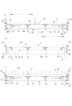
図1乃至図4に示すように、実施形態1に係る階段3は、階段3の踊り場5の床部2が柱装置1により支持された構成の階段であり、柱装置1は、例えば、床部2の長手方向の一端側に連結される一方の柱1Aと、床部2の長手方向の他端側に連結される他方の柱1Aと、床部2の長手方向の長さ間隔Lに対応した間隔を隔てて設けられた2つの各柱1A,1Aの上端1t,1t側間に亘って設けられて床部2の下面を支持する横架材1Bとを備えた柱装置、即ち、門型に形成された構成の柱装置である。
尚、各柱1A,1Aと横架材1Bとを結合する結合手段としては、例えば、溶接、又は、ガセットプレート及びボルトナット等の機械的結合手段が用いられる。
当該階段3の踊り場5の床部2が柱装置1により支持された構成の階段3によれば、柱の本数が少なくなるとともに、設計時において、床部2の短手方向(前後方向)に対する柱1A,1Aの取付位置を、任意に設定することが可能となる。
従って、階段3の踊り場5の床部2の下方の空間利用の制限を受け難くできるとともに、建物の意匠性向上を図れるようになる。
As shown in Figures 1 to 4, the
The means for connecting each
According to the
Therefore, restrictions on the use of the space below the
次に、踊り場の床部が上述した実施形態1の柱装置1により支持された構成の屋外の折り返し階段について説明する。
尚、本明細書において、前、後、内、外は、図2乃至図6に示した方向と定義して説明する。
また、図3、図5(b)~(d)は断面図であるが、断面ハッチングは省略してある。
Next, an outdoor turn-around staircase having a landing floor supported by the
In this specification, the terms front, rear, inside, and outside are defined as the directions shown in FIGS.
Although FIG. 3 and FIGS. 5(b) to (d) are cross-sectional views, cross-sectional hatching has been omitted.
図2に示すように、実施形態1に係る屋外の折り返し階段3は、階段部分4が踊り場5を介して折り返すように構成された例えば鋼材骨組(フレーム)構造の階段である。
即ち、折り返し階段3は、階段部分4が下階と上階との間を繋ぐ下側階段部分4A及び上側階段部分4Bを備えて構成され、踊り場5が下側階段部分4Aと上側階段部分4Bとの間に設けられた構成である。
例えば、折り返し階段3は、下側階段部分4Aが下階から斜め上方向に延長して踊り場5に到達した後、踊り場5において折り返して上側階段部分4Bが下側階段部分4Aの傾斜方向とは反対方向である斜め上方向に延長して上階の開放廊下6に到達するように構成された階段である。
As shown in FIG. 2 , the outdoor turn-around
In other words, the
For example, the
折り返し階段3の階段部分4(下側階段部分4A及び上側階段部分4B)は、左右一対のササラ桁40,40と、左右一対のササラ桁40,40間に設けられた段部構成部品41と、ササラ桁40より立ち上がるように設けられた手摺42とを備えて構成される。
ササラ桁40は、長尺材、例えば、平鋼(フラットバー)や溝形鋼等により構成される。
段部構成部品41は、例えば、板面が水平面となるように設置された複数の踏板43,43…と、板面が垂直面となるように設置された複数の蹴込板44,44…とで構成される(図2(c)参照)。
The stair section 4 (
The
The
踊り場5は、床部2と、手摺42とを備えて構成される。
床部2は、床下地構造体2Aと、当該床下地構造体2Aの上に例えば図外の複数の床材が並ぶように設置されて構成された床2B(図3参照)とを備える。
The
The
床下地構造体2Aは、階段部分4に近い側に位置する一方側桁21と、当該一方側桁21と間隔を隔てて平行に対向するように設けられた他方側桁22と、一方側桁21の延長方向の一端側と他方側桁22の延長方向の一端側とを繋ぐ一端側梁(妻梁)23と、一方側桁21の延長方向の他端側と他方側桁22の延長方向の他端側とを繋ぐ他端側梁(妻梁)24と、一方側桁21と他方側桁22とを繋ぐ根太25と、一方側桁21と他方側桁22とを繋ぐブレス材26とを備える。
換言すれば、床下地構造体2Aは、床2Bの長手方向の一端側に位置される一端側梁23と、床2Bの長手方向の他端側に位置される他端側梁24と、一端側梁23の一端側と他端側梁24の一端側とを繋ぐ一方側桁21と、一端側梁23の他端側と他端側梁24の他端側とを繋ぐ他方側桁22と、一方側桁21と他方側桁22とを繋ぐ根太25と、一方側桁21と他方側桁22とを繋ぐブレス材26とを備える。
尚、手摺42は、他方側桁22、一端側梁23、他端側梁24から立ち上がるように設けられている。
The
In other words, the
Furthermore, the
当該折り返し階段3では、下側階段部分4Aの外側のササラ桁40と床下地構造体2Aの一端側梁23とが一体物により構成され、かつ、上側階段部分4Bの外側のササラ桁40と床下地構造体2Aの他端側梁24とが一体物により構成される。
当該「一体物」とは、例えば、ササラ桁40と一端側梁23やササラ桁40と他端側梁24とが一体に形成された構成の一体物、あるいは、ササラ桁40と一端側梁23やササラ桁40と他端側梁24とが固定手段により接続されて一体化された構成の一体物のことをいう。
尚、当該固定手段としては、例えば、溶接等の固定手段、又は、ガセットプレート及びボルトナット等の機械的固定手段が用いられる。
In this turn-
The "integral object" in question refers to, for example, an integral object in which the
As the fixing means, for example, fixing means such as welding, or mechanical fixing means such as a gusset plate and bolts and nuts, etc. are used.
そして、柱装置1は、横架材1Bが根太25の下方に位置されて、根太25の下面と横架材1Bの上面とが接触した状態となるように、根太25と横架材1Bとが、連結手段により連結されたとともに、一方の柱1Aの上端側と一端側梁23とが連結手段で連結され、かつ、他方の柱1Aの上端側と他端側梁24とが連結手段で連結された構成とした。
尚、当該連結手段としては、例えばガセットプレートP及びボルトナットBN(図3参照)等の機械的連結手段、又は、溶接等の連結手段が用いられる。
このように、横架材1Bと根太25とが、連結手段により連結されたことで、部材同士の干渉による音鳴りを抑制できる。
また、根太25は、一方側桁21及び他方側桁22に固定手段で固定されている。当該固定手段としては、例えば、ボルトナットBN等の機械的固定手段、又は、溶接等の固定手段が用いられる。
The
The connecting means may be, for example, a mechanical connecting means such as a gusset plate P and bolts and nuts BN (see FIG. 3), or a connecting means such as welding.
In this way, the
The
即ち、実施形態1の柱装置1を用いて踊り場5の床部2が支持された構成である実施形態1の折り返し階段3は、踊り場5の床部2の全体が門型の柱装置1により支持された構造としたので、踊り場5の床部2の強度を保てるとともに、従来のように、階段の踊り場の床部の周囲における四方4箇所に柱を備えた構成と比べて、踊り場5の床部2の下方の空間利用の制限を受け難くできるとともに、建物の意匠性向上を図れるようになる。
また、下側階段部分4Aの外側のササラ桁40と床下地構造体2Aの一端側梁23とが一体物により構成されたとともに、上側階段部分4Bの外側のササラ桁40と床下地構造体2Aの他端側梁24とが一体物により構成されたので、踊り場5の床部2の強度をより向上させることができるようになった。
また、柱装置1は、柱1Aの本数が少なくなり、また、設計時において、床部2の前後方向(短手方向)に対する柱1A,1Aの取付位置を、任意に設定することが可能となる。従って、床部2の構造に合わせて、門型の柱装置1の柱1A,1Aの取付位置を最適な位置に調整することが可能となり、かつ、階段の踊り場の床部下方の空間利用の制限を受け難くできるとともに、建物の意匠性向上を図れるようになる。
また、一体物が多いため、現場施工での組み立て箇所が少なくなり、施工性が向上する。
In other words, the
In addition, the
Furthermore, the
In addition, since many of the components are one piece, there are fewer assembly points required during on-site construction, improving workability.
実施形態2
上述した実施形態1の柱装置1を用いて支持された構成の折り返し階段は、図5,図6に示す構成であっても良い。
尚、後述する構成以外の部分の構成は、実施形態1で説明した折り返し階段の構成と同じである。従って、図5,図6において、図1乃至図4に示した部分と同一又は相当する部分については、同一符号を付し、その説明を省略する。
即ち、実施形態2に係る折り返し階段3においては、図5,図6に示すように、床下地構造体2Xは、階段部分4に近い側に位置する一方側桁が、下側階段部分4Aに対応する部分21Xと上側階段部分4Bに対応する部分21Yとに分断されて、かつ、一端側梁23と他端側梁24との間の中央側に、一端側梁23及び他端側梁24と平行な一方の中央側補強部材27と他方の中央側補強部材28とを備えた構成とした。
そして、下側階段部分4Aの内側のササラ桁40と一方の中央側補強部材27とが一体物により構成されて、当該一体物と一方側桁の下側階段部分4Aに対応する部分21Xの分断された端部とが連結手段により連結されたともに、当該一体物と他方側桁22とが連結手段により連結された構成とした。
同様に、上側階段部分4Bの内側のササラ桁40と他方の中央側補強部材28とが一体物により構成されて、当該一体物と一方側桁の上側階段部分4Bに対応する部分21Yの分断された端部とが連結手段により連結されたともに、当該一体物と他方側桁22とが連結手段により連結された構成とした。
当該連結手段としては、例えば、溶接等の固定手段、又は、ガセットプレート及びボルトナット等の機械的固定手段が用いられる。
尚、「一体物」とは、例えば、ササラ桁40と一方の中央側補強部材27やササラ桁40と他方の中央側補強部材28とが一体に形成された構成の一体物、あるいは、ササラ桁40と一方の中央側補強部材27やササラ桁40と他方の中央側補強部材28とが固定手段により接続されて一体化された構成の一体物のことをいう。
当該固定手段としては、例えば、溶接等の固定手段、又は、ガセットプレート及びボルトナット等の機械的固定手段が用いられる。
The folded staircase supported by the
The configuration of the parts other than those described below is the same as that of the return staircase described in
That is, in the folded
The
Similarly, the
The connecting means may be, for example, a fixing means such as welding, or a mechanical fixing means such as a gusset plate and bolts and nuts.
In addition, "integral object" refers to, for example, an integral object in which the
As the fixing means, for example, fixing means such as welding, or mechanical fixing means such as a gusset plate and bolts and nuts, etc. are used.
そして、柱装置1は、横架材1Bが根太25の下方に位置されて、根太25の下面と横架材1Bの上面とが接触した状態となるように、根太25と横架材1Bとが、連結手段により連結されたとともに、一方の柱1Aの上端側と一端側梁23とが連結手段で連結され、かつ、他方の柱1Aの上端側と他端側梁24とが連結手段で連結される。
さらに、柱装置1は、横架材1Bが中央側補強部材27及び他方の中央側補強部材28の下方に位置されて、中央側補強部材27及び他方の中央側補強部材28の下面と横架材1Bの上面とが接触した状態となるように、柱装置1の横架材1Bと一方の中央側補強部材27及び他方の中央側補強部材28とが連結手段により連結された構成とした。
尚、当該連結手段としては、例えば、ガセットプレートP及びボルトナットBN(図5参照)等の機械的連結手段、又は、溶接等の連結手段が用いられる。
このように、横架材1Bと中央側補強部材27,28とが、連結手段により連結されたことで、部材同士の干渉による音鳴りを抑制できる。
The
Furthermore, the
The connecting means may be, for example, a mechanical connecting means such as a gusset plate P and bolts and nuts BN (see FIG. 5), or a connecting means such as welding.
In this way, by connecting the
実施形態2に係る折り返し階段によれば、下側階段部分4Aの内側のササラ桁40と一方の中央側補強部材27とが一体物により構成されて、上側階段部分4Bの内側のササラ桁40と他方の中央側補強部材28とが一体物により構成され、さらに、踊り場5の床部2の全体が門型の柱装置1により支持された構造としたので、実施形態1の階段と同じ効果が得られるとともに、踊り場5の床部2の強度をより向上させることができるようになった。
According to the folded staircase of
尚、各実施形態では、屋外の折り返し階段3の踊り場5の床部2が柱装置1により支持された構成の階段を例示したが、本発明に係る階段は、折り返し階段の踊り場の床部以外の床部が柱装置1により支持された構成の階段であってもよい。
例えば、屋外の直階段や廻り階段等の踊場の床部や、屋外の階段の上端と繋がる開放廊下の床部等が柱装置1により支持された構成の階段であってもよい。
また、屋内の階段の踊り場の床部や屋内の開放廊下の床部等が柱装置1により支持された構成の階段であっても良い。
In each embodiment, an example has been given of a staircase in which the
For example, the floor of a landing of an outdoor straight staircase or spiral staircase, or the floor of an open corridor connected to the top end of an outdoor staircase, may be a staircase configured in such a way that it is supported by the
In addition, the stairs may be configured such that the floor portion of a landing of an indoor staircase or the floor portion of an indoor open corridor is supported by the
また、実施形態では、間隔を隔てて設けられた2つの柱1A,1Aと各柱1A,1Aの上端1t,1t側間に亘って設けられた横架材1Bとを備えて門型に構成された柱装置1を例示したが、柱装置は、柱と、柱の上端側に設けられて床部下面の長手方向に沿って水平方向に延長する水平支持部材とを備えた構成であればよい。
即ち、本発明に係る階段の床部を支持する柱装置は、階段の踊り場の床部、又は、開放廊下の床部を支持する柱装置であって、床部の長手方向の一端側に連結される一方の柱と、一方の柱の上端側に設けられて床部の下面の長手方向に沿って延長して当該床部の下面を支持する水平支持部材と、床部の長手方向の他端側に連結される他方の柱と、他方の柱の上端側に設けられて床部下面の長手方向に沿って延長して当該床部下面を支持する水平支持部材とを備えた構成であってもよい。
そして、本発明に係る階段は、当該水平支持部材を備えた一方の柱と当該水平支持部材を備えた他方の柱とで構成された柱装置を用いて、床部が支持された階段であってもよい。
即ち、本発明の階段は、実施形態1,2で説明した階段の柱装置1の代わりに、上述した水平支持部材を備えた一方の柱と上述した水平支持部材を備えた他方の柱とで構成された柱装置を用いて支持された構成された階段であってもよい。
In addition, in the embodiment, a
In other words, the column device supporting the floor of a staircase according to the present invention may be a column device supporting the floor of a staircase landing or the floor of an open corridor, and may be configured to include one column connected to one longitudinal end side of the floor, a horizontal support member provided on the upper end side of the one column and extending along the longitudinal direction of the underside of the floor to support the underside of the floor, and the other column connected to the other longitudinal end side of the floor, and a horizontal support member provided on the upper end side of the other column and extending along the longitudinal direction of the underside of the floor to support the underside of the floor.
The staircase according to the present invention may be a staircase whose floor is supported using a column device constituted by one column having the horizontal support member and another column having the horizontal support member.
In other words, the staircase of the present invention may be a staircase supported using a column device composed of one column equipped with the above-mentioned horizontal support member and another column equipped with the above-mentioned horizontal support member, instead of the
また、実施形態では、鋼材骨組構造の踊り場付き階段を例示したが、本発明の構造は、鋼材骨組構造以外の、例えば木材骨組構造の踊り場付き階段にも適用可能である。 In addition, in the embodiment, a staircase with a landing made of a steel frame structure is shown as an example, but the structure of the present invention can also be applied to stairs with a landing made of a structure other than a steel frame structure, for example, a timber frame structure.
1 柱装置
1A 柱
1B 横架材(水平支持部材)
2 床部
2A,2X 床下地構造
2B 床
3 折り返し階段
4 階段部分
4A 下側階段部分
4B 上側階段部分、
5 踊り場
6 開放廊下
21 一方側桁
21X 一方側桁の下側階段部分に対応する部分
21Y 一方側桁の上側階段部分に対応する部分
22 他方側桁
23 一端側梁
24 他端側梁
25 根太
27 一方の中央側補強部材
28 他方の中央側補強部材
40 ササラ桁
1
2
5
Claims (4)
柱装置は、
床部の長手方向の一端側に連結される一方の柱と、一方の柱の上端側に設けられて床部の下面の長手方向に沿って延長して当該床部の下面を支持する水平支持部材と、床部の長手方向の他端側に連結される他方の柱と、他方の柱の上端側に設けられて床部の下面の長手方向に沿って延長して当該床部の下面を支持する水平支持部材とを備え、
水平支持部材が、床部の長手方向に間隔を隔てて設けられた一方の柱と他方の柱とに亘って設けられた横架材であることを特徴とする階段。 A staircase in which the landing floor or the open corridor floor is supported by a column device,
The pillar device is
The floor structure comprises one pillar connected to one end of the floor in the longitudinal direction, a horizontal support member provided on the upper end of the one pillar and extending along the longitudinal direction of the underside of the floor to support the underside of the floor, and another pillar connected to the other end of the floor in the longitudinal direction, and a horizontal support member provided on the upper end of the other pillar and extending along the longitudinal direction of the underside of the floor to support the underside of the floor,
A staircase characterized in that the horizontal support member is a cross member arranged across one pillar and the other pillar arranged at a distance from each other in the longitudinal direction of the floor portion.
折り返し階段の踊り場の床部は、床下地構造体と、当該床下地構造体の上に構成された床とを備え、
床下地構造体は、折り返し階段の階段部分に近い側に位置する一方側桁と、当該一方側桁と間隔を隔てて平行に対向するように設けられた他方側桁と、一方側桁の延長方向の一端側と他方側桁の延長方向の一端側とを繋ぐ一端側梁と、一方側桁の延長方向の他端側と他方側桁の延長方向の他端側とを繋ぐ他端側梁と、一方側桁と他方側桁とを繋ぐ根太とを備え、
折り返し階段の下側階段部分の外側のササラ桁と床下地構造体の一端側梁とが一体物により構成されたとともに、折り返し階段の上側階段部分の外側のササラ桁と床下地構造体の他端側梁とが一体物により構成され、
柱装置は、横架材が床下地構造体の下方に位置されて、一方の柱の上端側と一端側梁とが連結され、かつ、他方の柱の上端側と他端側梁とが連結されたことを特徴とする請求項1に記載の階段。 The staircase is a return staircase installed outdoors or indoors,
The floor portion of the landing of the turn-around staircase includes a floor substructure and a floor constructed on the floor substructure;
The floor understructure comprises: one side girder located on the side closer to the stair portion of the folded staircase; another side girder arranged parallel to and facing the one side girder at a distance; a one-end beam connecting one end side of the one side girder in the extension direction to one end side of the other side girder in the extension direction; an other-end beam connecting the other end side of the one side girder in the extension direction to the other end side of the other side girder in the extension direction; and a joist connecting the one side girder to the other side girder;
The outer rafter of the lower staircase part of the turn-around staircase and one end side beam of the floor base structure are formed as one piece, and the outer rafter of the upper staircase part of the turn-around staircase and the other end side beam of the floor base structure are formed as one piece,
The staircase described in claim 1, characterized in that the column device has a cross member positioned below the floor substructure, the upper end of one column is connected to the one-end beam, and the upper end of the other column is connected to the other-end beam.
折り返し階段の踊り場の床部は、床下地構造体と、当該床下地構造体の上に構成された床とを備え、
床下地構造体は、折り返し階段の階段部分に近い側に位置する一方側桁と、当該一方側桁と間隔を隔てて平行に対向するように設けられた他方側桁と、一方側桁の延長方向の一端側と他方側桁の延長方向の一端側とを繋ぐ一端側梁と、一方側桁の延長方向の他端側と他方側桁の延長方向の他端側とを繋ぐ他端側梁と、一方側桁と他方側桁とを繋ぐ根太とを備えるとともに、一方側桁が、下側階段部分に対応する部分と上側階段部分に対応する部分とに分断されて、かつ、中央側には、一端側梁及び他端側梁と平行な一方の中央側補強部材と他方の中央側補強部材とを備え、
折り返し階段の下側階段部分の外側のササラ桁と床下地構造体の一端側梁とが一体物により構成されたとともに、折り返し階段の上側階段部分の外側のササラ桁と床下地構造体の他端側梁とが一体物により構成され、
下側階段部分の内側のササラ桁と一方の中央側補強部材とが一体物により構成されて、当該一体物と一方側桁の下側階段部分に対応する部分の分断された端部とが連結されたともに、当該一体物と他方側桁とが連結され、
上側階段部分の内側のササラ桁と他方の中央側補強部材とが一体物により構成されて、当該一体物と一方側桁の上側階段部分に対応する部分の分断された端部とが連結されたともに、当該一体物と他方側桁とが連結され、
柱装置は、横架材が床下地構造体の下方に位置されて、当該横架材と一方の中央側補強部材及び他方の中央側補強部材とが連結されたとともに、一方の柱の上端側と一端側梁とが連結され、かつ、他方の柱の上端側と他端側梁とが連結されたことを特徴とする請求項1に記載の階段。 The staircase is a return staircase installed outdoors or indoors,
The floor portion of the landing of the turn-around staircase includes a floor substructure and a floor constructed on the floor substructure;
The floor understructure comprises one side girder located on the side closer to the stair portion of the folded staircase, the other side girder arranged parallel to and facing the one side girder at a distance, a one-end side beam connecting one end side of the extension direction of the one side girder to one end side of the extension direction of the other side girder, an other-end side beam connecting the other end side of the extension direction of the one side girder to the other end side of the extension direction of the other side girder, and a joist connecting the one side girder to the other side girder, the one side girder being divided into a portion corresponding to the lower stair portion and a portion corresponding to the upper stair portion, and comprising, on the central side, one central reinforcing member and the other central reinforcing member parallel to the one-end side beam and the other-end side beam,
The outer rafter of the lower staircase part of the turn-around staircase and one end side beam of the floor base structure are formed as one piece, and the outer rafter of the upper staircase part of the turn-around staircase and the other end side beam of the floor base structure are formed as one piece,
The inner slat of the lower staircase portion and one of the central reinforcing members are constructed as a single piece, and the single piece is connected to the divided end of the part corresponding to the lower staircase portion of one side girder, and the single piece is connected to the other side girder,
The inner slat of the upper staircase portion and the other central reinforcing member are constructed as a single piece, and the single piece is connected to the divided end of the part corresponding to the upper staircase portion of one side girder, and the single piece is connected to the other side girder,
The column device is characterized in that a cross member is positioned below the floor substructure, and the cross member is connected to one central reinforcing member and the other central reinforcing member, and the upper end side of one column is connected to one end beam, and the upper end side of the other column is connected to the other end beam.
4. The staircase according to claim 2 or 3, characterized in that the joists and the cross members of the column device are connected to each other.
Priority Applications (1)
| Application Number | Priority Date | Filing Date | Title |
|---|---|---|---|
| JP2023145815A JP2025039053A (en) | 2023-09-08 | 2023-09-08 | Stairs |
Applications Claiming Priority (1)
| Application Number | Priority Date | Filing Date | Title |
|---|---|---|---|
| JP2023145815A JP2025039053A (en) | 2023-09-08 | 2023-09-08 | Stairs |
Publications (1)
| Publication Number | Publication Date |
|---|---|
| JP2025039053A true JP2025039053A (en) | 2025-03-21 |
Family
ID=95024015
Family Applications (1)
| Application Number | Title | Priority Date | Filing Date |
|---|---|---|---|
| JP2023145815A Pending JP2025039053A (en) | 2023-09-08 | 2023-09-08 | Stairs |
Country Status (1)
| Country | Link |
|---|---|
| JP (1) | JP2025039053A (en) |
-
2023
- 2023-09-08 JP JP2023145815A patent/JP2025039053A/en active Pending
Similar Documents
| Publication | Publication Date | Title |
|---|---|---|
| JP4824157B2 (en) | Long escalator and moving walkway support structure | |
| JP2023084488A (en) | housing | |
| JP7193081B2 (en) | stair structure | |
| JP6507052B2 (en) | Unit building structure | |
| JPH07103653B2 (en) | Landing structure of stairs | |
| JPH01315541A (en) | Roof truss | |
| SU964083A1 (en) | Three-dimensional load-carrying lattice structure | |
| JP7506550B2 (en) | Partition wall for folded staircase | |
| JP7798737B2 (en) | handrail wall | |
| JP7299797B2 (en) | modular building | |
| JPH0433944B2 (en) | ||
| JP2001317169A (en) | Steel stairs, passage units | |
| JP2007146499A (en) | Building with stairs | |
| JP3967995B2 (en) | Unit building and its construction method | |
| JP6990066B2 (en) | Building balcony structure | |
| JPS6341419Y2 (en) | ||
| JP7095833B2 (en) | Outer staircase structure and unit building | |
| JP2025069545A (en) | building | |
| JP2000064545A (en) | Floor | |
| JPH1122129A (en) | Stair support structure | |
| JP3239321B2 (en) | Construction method of unit building | |
| JPH0788689B2 (en) | Connection structure of house frame structure | |
| JP2024073105A (en) | Building structure | |
| JP2664543B2 (en) | Stepboard unit for stairs | |
| JP4369274B2 (en) | Sasara girders and stairs using the sasara girders |
Legal Events
| Date | Code | Title | Description |
|---|---|---|---|
| A621 | Written request for application examination |
Free format text: JAPANESE INTERMEDIATE CODE: A621 Effective date: 20260722 |