JP2025006971A - Housing structure and construction method thereof - Google Patents
Housing structure and construction method thereof Download PDFInfo
- Publication number
- JP2025006971A JP2025006971A JP2023108049A JP2023108049A JP2025006971A JP 2025006971 A JP2025006971 A JP 2025006971A JP 2023108049 A JP2023108049 A JP 2023108049A JP 2023108049 A JP2023108049 A JP 2023108049A JP 2025006971 A JP2025006971 A JP 2025006971A
- Authority
- JP
- Japan
- Prior art keywords
- wall
- columns
- walls
- load
- beams
- Prior art date
- Legal status (The legal status is an assumption and is not a legal conclusion. Google has not performed a legal analysis and makes no representation as to the accuracy of the status listed.)
- Granted
Links
Images



Landscapes
- Load-Bearing And Curtain Walls (AREA)
- Buildings Adapted To Withstand Abnormal External Influences (AREA)
- Building Environments (AREA)
Abstract
Description
本発明は、住宅構造及び住宅構造の施工方法に関する。さらに詳しくは、軸組工法により形成されており、スケルトン・インフィル(Skeleton-Infill:SI)にも対応可能な住宅構造及び住宅構造の施工方法に関する。 The present invention relates to a residential structure and a construction method for the residential structure. More specifically, the present invention relates to a residential structure and a construction method for the residential structure that is formed using a framework construction method and can also accommodate skeleton-infill (SI).
従来の木造住宅の工法としては、軸組工法及び枠組壁工法が知られている。在来の軸組工法は、例えば、ポスト&ビーム工法等と呼ばれ、土台,柱,梁,筋交い等で建物の骨組をつくり、屋根や床等上部構造の荷重を主として柱により垂直方向に導き、土台ないし基礎に伝達させる工法である。 Traditional methods for constructing wooden houses include the post and beam method and the frame wall method. The traditional post and beam method, for example, is called the post and beam method, in which the framework of the building is made up of foundations, columns, beams, and braces, and the load of the upper structure, such as the roof and floor, is guided vertically mainly by the columns and transmitted to the foundation or base.
かかる軸組工法は、出入口や窓等開口部の配置や上部構造の荷重に合わせて材料を選択し、また、設計を比較的自由に行うことができるというメリットがあることが知られている(例えば、特許文献1等を参照。)。
This type of frame construction method is known to have the advantage that materials can be selected according to the placement of openings such as entrances and windows and the load of the superstructure, and that the design can be carried out relatively freely (see, for example,
軸組工法において、木材の組み付けによって形成された四角形状の壁面空間は、建築物の重みによる鉛直荷重及び地震や強風による水平荷重に対抗できるように、筋交いを配設してブレース構造にされている。この工法では、柱状の木材として、略正方形状の大断面からなる長尺材が用いられることも多い。 In the post and beam construction method, the rectangular wall space formed by assembling timber is braced with diagonal braces to withstand the vertical load caused by the weight of the building and the horizontal load caused by earthquakes and strong winds. In this construction method, long pieces of timber with a large, roughly square cross section are often used as the timber columns.
一方、枠組壁工法は、例えば、ツーバイフォー工法やプラットフォームフレーム工法等と呼ばれ、柱状の木材を鉛直方向及び水平方向に結合して建築物の枠組となる床枠組を形成し、かかる枠組に対して、構造物用合板等を打ち付けて耐力壁からなる壁枠組を形成するものである(例えば、特許文献2等を参照。)。
On the other hand, frame wall construction methods, known for example as the two-by-four method or platform frame method, involve joining wooden columns vertically and horizontally to form a floor framework that serves as the framework for a building, and then nailing structural plywood or the like to this framework to form a wall framework consisting of load-bearing walls (see, for example,
かかる床枠組及び壁枠組は、高価な材料や部材を使用することなく、規格品として大量に工場生産ができ、また現地施工性に優れているというメリットがあることが知られている。かかる工法で使用される木材は、構造用合板等を打ち付ける際の枠体となるものであればよく、例えば、長方形状の小断面の短尺材が用いられる。 Such floor and wall framing is known to have the advantage that it can be mass-produced as standardized products without using expensive materials or components, and is also easy to install on-site. The wood used in this construction method can be any material that can serve as a frame when structural plywood and the like are nailed to it, and for example, short pieces of wood with a small rectangular cross section are used.
これらの工法を比較すると、空間という観点では、軸組工法は「軸(線)」、枠組壁工法では「版(面)」で構成され、また、床面、壁面等の剛性付与構造は、軸組工法では「筋交い、火打ち梁、火打ち土台」、枠組壁工法では「構造用合板」であると考えられる。使用される木材は、軸組工法では、正方形を主とした大断面・長尺材(通し柱)を含み、枠組壁工法では、小断面・短尺材を主とするものを含む。そして、施工時の工程は、軸組工法では「一階・二階軸、床、小屋組」、枠組壁工法では「一階床、一階壁、二階床、二階壁、小屋(ステップ作業等。)」となると考えられる。 Comparing these construction methods, in terms of space, the post and beam method is composed of an "axis (line)," while the framed wall method is composed of a "plate (surface)." The structures that give rigidity to the floors, walls, etc. are thought to be "braces, fire beams, and fire bases" in the post and beam method, and "structural plywood" in the framed wall method. The wood used in the post and beam method includes large cross-section, long materials (through columns) that are mainly square, while the framed wall method includes mainly small cross-section, short materials. The construction process is thought to be "first and second floor axis, floor, truss" in the post and beam method, and "first floor floor, first floor wall, second floor floor, second floor wall, shed (step work, etc.)" in the framed wall method.
在来の軸組工法に着目すると、軸組工法は、前記したように、主として柱や梁といった文字通り軸組で支える工法であり、枠組壁工法と比較し耐力を持たせる壁が少ないため、設計の自由度が比較的高い工法である。耐震性を確保するために、軸組工法では、前記したように、筋交い、火打ち梁、火打ち土台等の斜め部材を用いる場合が多く、設計の自由度が高い。 Focusing on the traditional framework construction method, as mentioned above, the framework construction method is a method that is literally supported mainly by pillars and beams, and since there are fewer walls to be given strength compared to the frame wall construction method, it is a method with a relatively high degree of freedom in design. To ensure earthquake resistance, as mentioned above, framework construction often uses diagonal members such as braces, fire beams, and fire bases, allowing for a high degree of freedom in design.
ここで、軸組工法では鉛直荷重と共に地震力や風圧力に抗するために、建築基準法に定める基準に基づき必要な耐力壁を設置するが、耐力壁はできるだけ外周壁に設置するとともに、足りない部分を内部壁に設置するのが一般的である。しかしながら、外周壁に採光や換気上必要な窓や出入り口等の開口部を設けると、建築基準法に定める必要な耐力壁量が不足してしまう場合があり、その不足分を補う内部壁を別途設置する必要が生じる。 In framework construction, the necessary bearing walls are installed based on the standards set out in the Building Standards Act to withstand vertical loads as well as earthquake and wind forces. Generally, bearing walls are installed on the outer perimeter walls as much as possible, and any shortfalls are installed on the interior walls. However, when openings such as windows and entrances necessary for lighting and ventilation are installed on the outer perimeter walls, there are cases where the amount of bearing walls required by the Building Standards Act falls short, making it necessary to install separate interior walls to make up for the shortfall.
一方、利用ニーズや法令基準の採光面積等を確保するためには、自由度のある開口部の大きさや配置が望まれるが、外周壁においては、必要な耐力壁量を確保すると、開口部の大きさや配置に制約が多く生じ、内部壁においても、部屋の広さや形状、間仕切り、柱の配置等に多くの制約が生じることになる。 On the other hand, in order to ensure that the lighting area meets the needs of users and legal standards, it is desirable to have openings that are large and positioned with a certain degree of freedom. However, in the case of outer walls, ensuring the necessary amount of load-bearing wall material places many restrictions on the size and position of openings, and in the case of interior walls, there are also many restrictions on the size and shape of rooms, partitions, column placement, etc.
このように、必要耐力壁量を多くし建物強度を確保することと、自由に間仕切りや開口部等を設置する等の相容れない関係は多く生じており、外周壁も内部壁も建築基準法に定める耐震壁量の下限値を満たすことはあっても、安全性に余裕度のない建物となりがちであった。 As such, there is often a conflict between ensuring building strength by increasing the required amount of bearing walls and freely installing partitions and openings, etc., and even if the outer and inner walls meet the minimum earthquake-resistant wall amount set by the Building Standards Act, the building tends to have no margin of safety.
また、軸組工法の建物において、耐震に特化した耐力壁部分の技術は多く考案されているが、木材利用の合理的活用による建物全体の構造強化、構造体の長寿命化や、持続的に長期利用を可能にする、いわゆるスケルトン・インフィル(Skeleton-Infill:SI)、建替え寿命を延伸し、ライフサイクルコストを削減した、サスティナブルな建物等、社会的課題に対応した技術提案が求められている。 In addition, while many technologies have been devised for the load-bearing walls of buildings that use frame construction, there is a demand for technological proposals that address social issues, such as strengthening the structure of the entire building through the rational use of wood, extending the lifespan of structures, enabling long-term, sustainable use (so-called Skeleton-Infill: SI), and sustainable buildings that extend the lifespan before reconstruction and reduce life cycle costs.
このような背景から、近年、長期間の耐久性を有しつつ、居住空間の可変性を有する、前記したSI住宅の開発・普及が求められている。ここで、SI住宅におけるスケルトン(Skeleton)は、住宅の柱や梁などの構造部分を意味し、インフィル(Infill)は、住宅の間取りや内装などを意味する。 In light of this, there has been a demand in recent years for the development and popularization of the above-mentioned SI housing, which has long-term durability while allowing for variability in living space. Here, in SI housing, the skeleton refers to the structural parts of the house, such as the pillars and beams, and the infill refers to the layout and interior of the house.
SI住宅は、かかるスケルトンとインフィルとを分離した構成とし、スケルトンを高強度に構築して長期間の耐久性を有するようにしつつ、間取りや内装などの可変性を有するようにした住宅である。SI住宅は、長く住むことができ、かつ、住人のライフスタイルや家族構成の変化に合わせて、あるいは住人の多様なニーズに応えて、比較的容易にリフォームできるようにしたものである。 SI homes are constructed with a separate skeleton and infill, with a skeleton that is constructed to be highly strong and durable for the long term, while allowing for variability in layout and interior design. SI homes are long-lived homes that can be remodeled relatively easily to suit changes in the residents' lifestyles and family structures, or to meet the diverse needs of the residents.
加えて、近年、構造体を残したスケルトンリフォ-ムや断熱性能の向上を目的とした断熱リフォームなどが増え、気密性・断熱性を高め、省エネルギー効果と快適性とを有するようにした、いわゆる高気密・高断熱住宅の開発・普及も求められている。そして、木質パネル工法の住宅などでは、SI化と高強度、高気密、高断熱化とを兼ね備えたものが種々開発、提供されている。 In addition, in recent years, there has been an increase in skeleton reforms that leave the structure intact, and insulation renovations aimed at improving insulation performance, and there is a demand for the development and popularization of so-called highly airtight and insulated homes that have improved airtightness and insulation, energy savings, and comfort. In addition, various homes using wood panel construction methods have been developed and provided that combine silicon ion (SI) with high strength, high airtightness, and high insulation.
SI化と高気密・高断熱化とを両立させた住宅の開発・普及は、パネル工法の住宅のみならず、木造軸組工法の住宅においても求められている。しかしながら、木造軸組住宅において、高強度、高気密、高断熱化を維持して、高い耐震性を確保しながら、自由度のある間取りや開口部の量と配置、長期利用等の実現に応えられるスケルトン・インフィル住宅に対応することは、難しい問題であった。 The development and popularization of houses that combine system integration with high airtightness and insulation is required not only for houses built using panel construction methods, but also for houses built using wooden frame construction methods. However, with wooden frame construction methods, it has been difficult to create skeleton-infill houses that can accommodate flexible floor plans, the number and placement of openings, and long-term use while maintaining high strength, airtightness, and insulation and ensuring high earthquake resistance.
地震国である日本における木造住宅の耐震性や構造的課題は大地震が発生するたびに顕在化し、構造基準の見直しや施工方法の適正化が求められることになる。また、近年の建築における地球温暖化防止という社会課題や、消費エネルギーの削減に対応するためにも、二酸化炭素(CO2)削減のために、省エネルギー住宅における断熱基準の見直しや制度・基準の改正等が実施されており、住宅においても一層の省エネルギーと断熱性能の向上が求められることになる。 In Japan, an earthquake-prone country, the earthquake resistance and structural problems of wooden houses become apparent every time a major earthquake occurs, and there is a demand for reviewing structural standards and optimizing construction methods. In addition, in order to address the social issue of preventing global warming in recent years in construction and to reduce energy consumption, the insulation standards for energy-saving houses have been reviewed and systems and standards have been revised to reduce carbon dioxide ( CO2 ), and further energy conservation and improved insulation performance are required in houses as well.
加えて、木材の有効活用、省資源、長期利用が可能なサスティナブルな建築技術、建築物のライフサイクルコストの見直しの観点からも、住宅構造の耐久性向上や建物寿命の延長の方策等が必要とされている。こうした時代や社会的要請に対応すべく、木造住宅でもっとも建設棟数が多い軸組工法の住宅の領域における、高強度と高気密性を備えた新しい住宅構造と、それにより建替え寿命を延ばすことが可能な高断熱性能による住宅が望まれている。 In addition, from the perspective of effective use of wood, resource conservation, sustainable building techniques that allow long-term use, and a review of the life cycle costs of buildings, there is a need for measures to improve the durability of housing structures and extend the life cycle of buildings. In order to respond to these times and social demands, there is a demand for new housing structures with high strength and airtightness in the field of post-and-beam construction, which is the most common type of wooden house built, as well as homes with high insulation performance that can extend the lifespan before they need to be rebuilt.
本発明は前記のような問題を解決するためになされたものであり、木造軸組工法を用いた住宅構造であって、木造住宅に求められる高強度、高気密性及び高断熱性を維持し、スケルトン・インフィル住宅にも対応可能な住宅構造及び住宅構造の施工方法を提供することにある。 The present invention has been made to solve the above problems, and aims to provide a housing structure and construction method for a housing structure that uses wooden frame construction and maintains the high strength, airtightness, and insulation required of wooden houses, and is also suitable for skeleton-infill housing.
前記の課題を解決するために、本発明に係る住宅構造は、
壁、柱、梁を備えた木造軸組構造からなる住宅構造であって、
外周部における柱のうち、構造グリッドを構成する位置に配される柱が、複数本の角柱を束ねた束ね柱であり、
前記外周部の前記束ね柱に挟まれる範囲に配される前記梁が、合せ梁を含み、
前記外周部の前記束ね柱に挟まれる範囲に配される前記壁が、厚さ方向から見て2枚以上で形成され、前記2枚以上の壁のそれぞれが耐力構造を備える壁で形成される部分を含み、
前記壁のそれぞれが、断熱機能を備える、
ことを特徴とする。
In order to solve the above problems, the housing structure according to the present invention comprises:
A residential structure consisting of a wooden frame structure with walls, pillars, and beams,
Among the columns in the outer periphery, columns arranged at positions constituting a structural grid are bundled columns each comprising a plurality of square columns;
The beams arranged in the range sandwiched between the binding columns of the outer periphery include a joint beam,
The wall arranged in the range sandwiched between the binding columns of the outer periphery is formed of two or more walls when viewed from the thickness direction, and each of the two or more walls includes a portion formed of a wall having a load-bearing structure,
Each of said walls has a thermal insulation function.
It is characterized by:
本発明に係る住宅構造は、前記した本発明において、
前記外周部に配される前記耐力構造を備える壁が、内部外周壁及び外部外周壁の2枚で形成される部分を含み、
前記内部外周壁及び前記外部外周壁のそれぞれが耐力構造及び断熱機能を備えることを特徴とする。
The housing structure according to the present invention is the above-mentioned present invention,
The wall having the load-bearing structure arranged on the outer periphery includes a portion formed of two walls, an inner outer periphery wall and an outer outer periphery wall,
The inner peripheral wall and the outer peripheral wall each have a load-bearing structure and a heat-insulating function.
本発明に係る住宅構造は、前記した本発明において、
前記外周部の隅に配される前記柱が、2本×2本の計4本からなる束ね柱であることを特徴とする。
The housing structure according to the present invention is the above-mentioned present invention,
The pillars arranged at the corners of the outer periphery are bundled pillars consisting of two pillars x two pillars, for a total of four pillars.
本発明に係る住宅構造は、前記した本発明において、
建築基準法に定める地震力に抗する壁量充足率、及び風圧力に抗する壁量充足率(前記壁量充足率については下記式(X)を参照。)がそれぞれ1.0を超えるように、前記束ね柱、前記合せ梁及び前記2枚以上の壁のそれぞれが耐力構造を備える壁で形成される部分を配することを特徴とする。
壁量充足率=(存在壁量/必要壁量)>1.0 …… (X)
The housing structure according to the present invention is the above-mentioned present invention,
The present invention is characterized in that the bundle columns, the joint beams and the two or more walls each have a portion formed of a wall having a load-bearing structure so that the wall volume fulfillment rate against earthquake force and the wall volume fulfillment rate against wind pressure (see formula (X) below for the wall volume fulfillment rate) specified in the Building Standards Act each exceed 1.0.
Wall amount sufficiency rate = (existing wall amount / required wall amount) > 1.0 ... (X)
本発明に係る住宅構造を施工する方法は、前記した本発明の住宅構造を施工する方法であって、
建築基準法に定める地震力に抗する壁量充足率、及び風圧力に抗する壁量充足率(前記壁量充足率については下記式(X)を参照。)がそれぞれ1.0を超えるように、前記束ね柱、前記合せ梁及び前記2枚以上の壁のそれぞれが耐力構造を備える壁で形成される部分を配するように施工することを特徴とする。
壁量充足率=(存在壁量/必要壁量)>1.0 …… (X)
The method for constructing a housing structure according to the present invention is a method for constructing the housing structure according to the present invention described above,
The construction is characterized in that the bundle columns, the joint beams, and the two or more walls are each constructed so that their portions are formed of walls having load-bearing structures, so that the wall volume fulfillment rate for resisting earthquake forces and the wall volume fulfillment rate for resisting wind pressure (see formula (X) below for the wall volume fulfillment rate) specified in the Building Standards Act each exceed 1.0.
Wall amount sufficiency rate = (existing wall amount / required wall amount) > 1.0 ... (X)
本発明に係る住宅構造は、外周部に束ね柱、合せ梁及び厚さ方向から見て2枚以上で形成される耐力壁(耐力構造を備える2枚壁)で形成される部分を設けて、外周部に高強度な耐力構造を備えるようにしている。かかる構造により、外部から受ける地震力や風圧力に抗し、劣化や破損しやすい建物外周部を、強固で一体的な外殻を形成する、いわば(セミ)モノコック構造とし、合わせて、内部に格子状の構造グリッドを形成して強度を確保することで、外周部に耐力構造を集中することが可能となる。その結果、本発明に係る住宅構造は、強度を備えた上で、住宅の内部に耐力壁や柱、梁等の設置箇所を減らせ、部屋の仕切り壁位置を制約しないで広がりのある空間利用が可能な、耐力壁や柱、梁等の部材の使用について自由度と選択肢を増やすことが可能となる。 The housing structure according to the present invention has a section on the periphery formed of bundled columns, joint beams, and load-bearing walls (two walls with load-bearing structure) formed of two or more sheets when viewed in the thickness direction, providing a high-strength load-bearing structure on the periphery. This structure makes it possible to resist earthquake forces and wind pressure from the outside and to form a strong, integrated outer shell around the building's periphery, which is prone to deterioration and damage, into a (semi-)monocoque structure, and by forming a lattice-like structural grid inside to ensure strength, it is possible to concentrate the load-bearing structure on the periphery. As a result, the housing structure according to the present invention is strong, and can reduce the number of installation locations for load-bearing walls, columns, beams, etc. inside the house, allowing for more freedom and options in the use of components such as load-bearing walls, columns, beams, etc., allowing for more expansive space utilization without restricting the position of room partition walls.
加えて、本発明に係る住宅構造は、外周部に配される2枚以上で形成される壁のそれぞれが断熱機能を備えるので、高気密となるとともに、通常の1枚の壁からなる住宅構造の断熱性能と比較して倍ないしはそれ以上の断熱材の厚みを利用して、寒冷地から高温暖地に至るまでの広範な地域の「建築物エネルギー消費性能基準等に定める省令」の基準や、国土交通省の示す上位の断熱基準となるHEAT20の高断熱基準の性能を備えた、高強度で高耐震、高気密で高断熱という、建物に必要な複数の性能等を同時に実現できる住宅構造にすることができる。 In addition, the housing structure of the present invention has two or more walls arranged around the perimeter that each have insulating properties, making it highly airtight, and by utilizing the thickness of the insulating material that is twice or more thicker than that of a normal housing structure consisting of a single wall, it can be made into a housing structure that simultaneously achieves multiple performance requirements for a building, such as high strength, high earthquake resistance, high airtightness, and high insulation, and that meets the standards of the Ministerial Ordinance Prescribing Energy Consumption Performance Standards for Buildings in a wide range of regions from cold to hot and warm climates, as well as the high insulation standard of HEAT20, which is the higher insulation standard set by the Ministry of Land, Infrastructure, Transport and Tourism.
そして、本発明に係る住宅構造の施工方法は、前記した本発明の住宅構造を施工する方法であって、式(X)により求められる、建築基準法に定める地震力に抗する壁量充足率、及び風圧力に抗する壁量充足率がそれぞれ1.0を超えるように、束ね柱、合せ梁及び耐力構造を備える2枚壁で形成される部分を配するようにして施工するので、前記した効果を好適に奏する施工方法となる。 The construction method of the housing structure of the present invention is a method of constructing the housing structure of the present invention described above, in which the parts formed of two walls equipped with bundle columns, joint beams, and load-bearing structures are arranged so that the wall volume sufficiency rate for resisting earthquake forces and wind pressure as stipulated in the Building Standards Act, calculated by formula (X), each exceeds 1.0, making this a construction method that optimally achieves the effects described above.
以下、本発明に係る住宅構造1の一態様について説明する。
Below, one aspect of the
(I)軸組工法住宅の一般的な住宅構造1について:
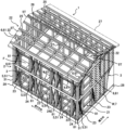
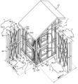
図1ないし図3は、木造軸組構造からなる住宅構造1の一態様を示した斜視図であり、図1は、屋根27の野地板Nの一部を取り外した状態、図2は、屋根27を取り外した状態、図3は、屋根27に覆われた部分を示すため、屋根27を上に移動した状態、をそれぞれ示す。なお、図1ないし図3では、例として、2階建ての住宅構造1を載せ、図1では、説明の便宜上、内部構造の一部を省略し、「構造グリッド」を示すようにしている。また、図1~図3を含む全ての図に共通するが、載せられる部材の全てに符号は付されてはいない。
(I)
Figures 1 to 3 are perspective views showing one embodiment of a
一般に、木造軸組構造からなる住宅構造1は、図1ないし図3に示すように、まず、所定の(木製の)角材で柱5や梁6等を形成して、床組21及び小屋組22を含む木造軸組2を構成し、さらに、所定の板(板材)を、壁板W、床板F、野地板N(場合によって天井板。)等として、これらをかかる木造軸組2に固定することで形成される構造である。なお、本発明でいう「外周部3」とは、住宅構造1の外周を形成している部分である。
Generally, as shown in Figures 1 to 3, a
図1等に示す住宅構造1は、外周に立ち上がった外周部(2重)土台23(外周部3を構成する場合、例えば、2階床梁、小屋梁では後記する梁6ないしは合せ梁61ともなる。以下同じ。)を基礎28と固定している。図面が複雑になるので図1等にあっては図示しないが、さらに、外周部(2重)土台23の間に屋内側大引き24(図2等参照。)が架設されて床組21が形成されるのが一般的である。
The
なお、外周部(2重)土台23(以下、単に「土台23」とする場合もある。)と屋内側大引き24(以下、単に「大引き24」とする場合もある。)との接合部、及び屋内側大引き24同士の接合部には、図示しない仕口や接合金物で土台23や大引き24に固定されたこれも図示しない梁受金物仕口等によって、屋内側大引き24の端部等を受けて固定するのが一般的である。また、床組21の構成としては、前記した基礎28のほか、例えば、図示しない根太等によって形成される床組21も周知であり、これらの床組21を適用しても問題はない。
The joints between the outer (double) base 23 (hereinafter sometimes simply referred to as "
基礎28からなる床組21の上には、その土台23の上に柱5が立設されている。なお、外周部3に立設される柱5は、本発明にあっては、構造グリッドを構成する位置に配される柱に束ね柱51が用いられており、図1等でもそのように示されているが、これについては後記する。
外周部3の柱5の上には、1階と2階の間に、梁6が固定されている。外周部3の梁6は、本発明にあっては、外周部3の束ね柱51に挟まれる範囲に配される梁6として、合せ梁61(合わせ梁とも記載される。以下同じ。)を含むようにしており、図1等でもそのように示されているが、これについても後記する。また、外周部3に配設される梁6で囲まれる内部には、幅方向と長さ方向(幅方向と直交する方向。幅方向と長さ方向については図1~図3の矢印方向を参照。)に対して梁6(図2、図3に大引き24として示している。なお、図2及び図3では、柱5(重ね柱51)と繋がる大引き24を、屋内側土台24Dとして示したところもある。)となって架け渡されており、かかる大引き24が、平面視(住宅構造1を真上から見る方向。)した場合に略十字となるように配置されている。
かかる梁6の上方向に位置する2階にも、かかる梁6の上に柱5が立設されており、外周部3には、かかる柱5の上に梁6が固定される。外周部3の梁6は合せ梁61が使用されることは同様であり、かかる梁6の幅方向と長さ方向に対して図示しない梁6(大引き24)が架け渡されて、平面視した場合に略十字となるように配置されていることも同様である。
On the second floor, located above the
幅方向と長さ方向に梁6(2階の上部では合せ梁61ともなる。図1~図3でもそのように載せている。)を構成し、及び柱5との接合部は、図示しないが、それぞれ仕口や接合金物等によって、梁6等の端部を受けて固定している。
Beams 6 (which are also joint beams 61 at the top of the second floor, and are shown as such in Figures 1 to 3) are formed in the width and length directions, and the joints with the
また、屋根27における一番高い位置にある部材となる棟木26と平行に、母屋25が所定のピッチで架設され、2階の梁6の上には、小屋束5T(こやづか。前記した「束ね柱61(たばねばしら)」とは異なる。)が立設されており、小屋束5Tの上に棟木26や母屋25が架設されている。また、棟木26の両側の側面から梁6に向かって、図示しない垂木が所定のピッチで架設されており、これらの梁6、小屋束5T、母屋25、及び図示しない垂木によって小屋組22が形成されることになる。
The
そして、このようにして形成された床組21及び小屋組22を含む木造軸組2に対して、壁7(壁板W)、床板F、野地板N(場合によって天井板。)等の所定の板(板材)を固定することで、図1等に示すような住宅構造1が形成される。本発明にあっては、(図6等を用いて説明するので、前記した図1~図3には積極的には載せていないが)外周部3に配される壁7が、厚さ方向から見て2枚以上で形成され、2枚以上の壁のそれぞれが耐力構造を備える壁71(以下、「耐力構造を備える2枚壁71」とするところもある。)で形成される部分(図1~図3において、筋交い81が配設されている部分がそれに相当する。なお、符号81は一部に付している。)を含み、かつ、壁7のそれぞれが、断熱機能を備えるものであるが、これについては後記する。
Then, the
(II)本発明に係る住宅構造1について:
次に、前記した住宅構造1に適用される、本発明に係る住宅構造1について説明する。なお、以下に載せる基本構成を「本発明の基本構成」とする場合もある。
本発明に係る住宅構造1は、
壁7、柱5、梁6を備えた木造軸組構造からなる住宅構造1であって、
外周部3における柱5のうち、構造グリッドを構成する位置に配される柱5が、複数本の角柱を束ねた束ね柱51であり、
前記外周部3の前記束ね柱51に挟まれる範囲に配される前記梁6が、合せ梁61を含み、
前記外周部3の前記束ね柱51に挟まれる範囲に配される前記壁7が、厚さ方向から見て2枚以上で形成され、前記2枚以上の壁7のそれぞれが耐力構造を備える壁7で形成される部分を含み、
前記壁7のそれぞれが、断熱機能を備える、
ことを基本構成として備える。
(II) Regarding the
Next, a description will be given of the
The
A
Among the
The
The
Each of said
The basic configuration is as follows.
(II-1)柱5について:
柱5は、床組21の上に垂直方向(軸方向)に立設される。外周部3における交差位置に配される柱5における構造グリッドを構成する位置には、束ね柱51が使用される。ここで、「束ね柱51」とは、複数の柱5を束ねて(集合させて)一体化した柱5のことを指す。また、「交差位置(交差する位置)」とは、構造部材が接合等される位置を指す。束ね柱51を使用することにより、主として鉛直荷重、積載荷重に対する強度が向上する。
(II-1) Regarding Pillar 5:
The
ここで、構造グリッドとは、隣接する2個の基準四角形が1辺および両方の角を共有し、1フロアの床面上で複数の基準四角形が1列をなすように連続して形成されるものであり、柱5、梁6、壁7で構成された構造フレームを立体的に組み合わせるための基本となる立体格子状のグリッド線の集まりを呼ぶものである。また、構造グリッドを構成する位置とは、かかる構造グリッドにおける隅となる位置(一般に4隅であり、本発明にあっては、そのうちの外周部3に配される箇所が相当。)を指す。
The structural grid is a set of three-dimensional grid lines that are the basis for combining structural frames made up of
束ね柱51の構成する1本の柱5は、角柱からなり、断面を矩形状とすることが好ましく、断面が略正方形状とすることが特に好ましい。また、束ね柱51を構成する柱5は、断面が同じ形状のものを使用することが好ましく、断面が同じとなる、略正方形状の柱5を使用することが好ましい。
Each of the
束ね柱51は、後記する図4や図5にその一例を示すように、束ね柱51を構成する1本の柱5を2本並べて構成されるものや、住宅構造1と垂直方向に2本、平行方向に2本(垂直方向、平行方向は後記する図4等に載せている。)並べてなる、2本×2本の合計4本から構成されることが好ましい。
As shown in Figures 4 and 5 below, the bundling columns 51 are preferably made up of two
束ね柱51は、構成する柱5の数が多いほど、強度が向上する。図1等に示すように、外周部3の隅31(あるいは外周壁の隅31)に配される柱5については、4本(2本×2本)から構成される束ね柱51を用いることが好ましい。また、前記した隅31以外の交差位置については、必要とされる強度に応じて4本(2本×2本)の束ね柱51としてもよいし、2本の束ね柱51としてもよい。図1等にあっては、外周部3の隅31については、4本(2本×2本)から構成される束ね柱51、外周部3の隅31以外の交差位置については、2本の束ね柱51とした態様を示している。なお、束ね柱51を2本の柱から形成されるようにする場合は、柱5を、壁7の厚さ方向とあわせて並べて配設することが好ましい。
The strength of the bundling columns 51 increases with the number of
束ね柱51を構成する1本の柱5のサイズは、特に制限はないが、SDGs(Sustainable Development Goals:持続可能な開発目標)や小径木木材の有効活用の観点から、大断面部材を使用したり、集成材などの二次加工を必要としない、一般流通木材を合理的に用い、小断面の略正方形状とした場合、かかる断面における1辺の長さを105~120mmとすることが好ましい。また、105mm×105mm(105mm角)や120mm×120mm(120mm角)のものを使用することが好ましい。
There are no particular restrictions on the size of each
(II-2)梁6について:
図4は、束ね柱51と合せ梁61の一例を示した図(束ね柱51を断面としている。)、図5は、束ね柱51と合せ梁61の接合状態の一例を示した図である。なお、図4及び図5中、(A)~(D)に示した束ね柱51と合せ梁61のほか、(E)を参考図として、単柱(1本の柱5)と単梁(1本の梁6)の組み合わせを載せている((A)は外周部3の隅31、(B)及び(D)は外周部3のうち並列される壁7を繋ぐ位置、(C)及び(E)は内部に配される構成である。)。
(II-2) Regarding Beam 6:
Fig. 4 is a diagram showing an example of a bundling column 51 and a joint beam 61 (the bundling column 51 is shown in cross section), and Fig. 5 is a diagram showing an example of the joint state of the bundling column 51 and the joint beam 61. In Figs. 4 and 5, in addition to the bundling columns 51 and joint beams 61 shown in (A) to (D), (E) is a reference diagram showing a combination of a single column (one column 5) and a single beam (one beam 6) ((A) is the
本発明において、外周部3の束ね柱51に挟まれる範囲に配される梁6は、合せ梁61を含む。本発明において合せ梁61とは、2本ないしはそれ以上の梁6を合わせて(重ねて)形成される梁6を指し、図1等では、前記した土台23も合せ梁61となる態様を示している。図4や図5に示すように、束ね柱51として2本や4本(2本×2本)の柱5とする場合、梁6から見て、束ね柱51は2本並んでいると接合も効率よく進む等の理由で、梁6の合わせる方向は、柱5の立設方向と直交する方向(壁7の厚さ方向ともなる。)に合わせて(重ねて)形成されることが好ましい。
In the present invention, the
なお、本発明にあっては、外周部3に配される梁6について合せ梁61とされる部分を含むことにより、単梁(1本の梁6)を使用する場合と比較して、外周部3の強度(主として鉛直荷重及び水平力に対する強度)が向上し、複数本による荷重分散によりサイズダウンを図りながら向上することになる。
In addition, in the present invention, the
住宅構造1において、梁6は柱5と接合され、本発明に係る住宅構造1における合せ梁61は、前記した束ね柱51と接合される。本発明にあっては、外周部3の交差位置に配される柱5を束ね柱51としているが、合せ梁61を構成する梁6のサイズのうち、厚さ方向は、前記した束ね柱51を構成する1本の柱5と共通させることが好ましい。
In the
(II-3)壁7について:
外周部3において、束ね柱51に挟まれる範囲に配される壁7は、厚さ方向(壁7を積層する方向であり、図6や図8を参照。)から見て2枚以上(多重)で形成され、かかる2枚以上の壁7のそれぞれが耐力構造を備える壁71(耐力構造を備える2枚壁71)で形成される部分を含み、壁7のそれぞれが、断熱機能を備えている。以下、外周部3の壁7を2枚(2重)とした態様を例として説明するが、本発明で用いる「耐力構造を備える2枚壁71」という表現は、2枚(2重)を超える壁7の枚(重)数(例えば、3枚(3重)。)を含むものである。なお、「2枚以上の壁7が耐力構造を備える壁71(耐力構造を備える2枚壁71)を含み、」とは、構造グリッドにおける外周部3を構成する壁7について、2枚以上の壁7が耐力構造を備える壁71となる部分を含んでいることを指す。
(II-3) Regarding Wall 7:
In the
2枚とされた壁7(外周壁(外周部3の壁7))は、本実施形態にあっては、外周部3に配される耐力構造を備える壁7が、外部外周壁(外周部3側に配される外周壁)7Gと内部外周壁(内部側(外部外周壁7Gより内部側)に配される外周壁)7Nとからなる態様を示している。外部要因により劣化しやすい外周部3の壁7(耐力壁:耐力構造を備える壁)を2重化し、モノコック構造とすることで高強度化でき、外周壁の内部と外部を区別することにより、リフォーム・リノベーションの際の区分施工が容易となり、構造体の厚みの範囲内に囲われる状態で断熱材72が存在し、外部の防水ラインの内側に構造体と断熱材72(後記する図6等参照。)を形成することで、建物の長期維持、利用が可能な、長寿命な住宅を提供することができる。
In this embodiment, the two walls 7 (periphery wall (
図6ないし図9は、外周壁の構造の一例を示した図である。なお、図6では、主要な構造部材のみについて載せており、耐力構造を備える2枚壁71を分解して載せている(符号は、後記する図10、図15も含めて、図面の右方に載せる耐力構造を備える2枚壁71については、簡略化して載せている。)。また、図7(正面図)、図8及び図9(断面図)で、耐力構造を備える2枚壁71を形成する詳細な部材等について載せている。
Figures 6 to 9 show an example of the structure of the outer perimeter wall. Note that in Figure 6, only the main structural members are shown, and the two
また、外周壁は、壁7が耐力構造を備える2枚壁71で形成されて耐力構造を備える部分を含み、図6等にあっては、2枚の内部外周壁7Nと外部外周壁7Gのそれぞれが耐力構造を備え、構造強度上も壁倍率を2枚分加算した高耐力壁として機能する。壁7のそれぞれが耐力構造を備える部分を含むことから、耐力壁としての強度(主として水平荷重、鉛直荷重。)が向上する。また、外周部3の構造が、壁7が2重(多重)になる等の2重構造から形成されるので、高い気密性も維持される。
The outer peripheral wall also includes a portion having a strength-bearing structure, with the
本発明にあっては、外周部3において、前記した束ね柱51及び合せ梁61の使用と併せ、外周部3の厚さ方向に耐力構造を重ねて配する部分あるいは一体的で連続的なモノコック構造を形成するようにしているので、外周部3の強度等を向上させることができ、その結果、住宅構造1の内部側が過度の強度を必要とすることなく、耐力壁を含む壁7や柱5をできる限り少なくすることが可能な、住宅内部に広がりと自由度のある空間のバリエーションを与えることができる住宅設計を行うことが可能となる。
In the present invention, in addition to using the aforementioned bundled columns 51 and joint beams 61 in the
また、内部外周壁7Nと外部外周壁7Gのそれぞれが断熱機能を備え、このように、2枚以上で形成される壁7のそれぞれが断熱機能を備えるので、一般的な単層の断熱材72を備えた壁7で形成される住宅構造1と比較して、構造体の厚みの範囲内に囲われる状態で断熱材が存在し、外部の防水ライン(例えば、透湿防水シート84等。)の内側に構造体と断熱材72が形成することで、断熱特性と耐久性に優れた住宅構造1となる。
In addition, each of the internal outer
なお、壁7に対して断熱機能を付与するには、断熱材72(層状のものであれば、断熱層と呼ばれる。)を備えるようにすることが一般的である。用いられる断熱材72(断熱層)の種類等は特に制限はなく、地域ごとに定められた断熱地域区分等に応じて、適宜決定することができる。なお、本明細書においては、便宜上、断熱機能を備えることについて、断熱材72(断熱層)を備えると載せているところもある。
In addition, in order to provide the
また、耐力壁として配される壁7とは、耐力を必要としない部分(例えば、扉、窓等といった部分。)を除いた部分に配される、住宅構造1として耐力を必要とされる部分に配される壁7を指す。また、図6等に示した例のように、内部外周壁7Nと外部外周壁7Gのそれぞれが耐力構造を備える(ないしは備える部分を含む。)ようにすれば、住宅構造1の強度や耐震性等が向上するので好ましい。
The
以下、外周壁の構造の一例として、外部外周壁7Gと内部外周壁7Nのそれぞれが、たすき掛けした筋交い81を備えた耐力壁とされ、外部外周壁7Gに耐力面材82を備えたものを外周壁(外周部3の壁7)の構造として用いたものを説明する。
Below, as an example of the structure of the outer peripheral wall, we will explain a structure in which the outer
図6、図7~図9に示した構造は、まず、外部外周壁7Gとして、外部から内部に向かって、外壁材83、透湿防水シート84、耐力面材82が配設されている。また、かかる耐力面材82の内部側には、間柱85を備えた、たすき掛けされた筋交い81が配設されており、断熱機能を持たせるため、断熱材72が、筋交い81により形成された空間を充てんするように配設されている。
In the structure shown in Figures 6 and 7 to 9, first, an
なお、図8等に示した態様にあっては、外壁材83と透湿防水シート84との間には通気層86が形成されている。また、外壁材83の裏側には、外壁材83を束ね柱51に固定するために、縦胴縁87が配設されている例を示している。
In the embodiment shown in FIG. 8, etc., a
また、内部外周壁7Nとして、外部から内部に向かって、間柱85を備えた、たすき掛けされた筋交い81、気密シート88、石膏ボードからなる壁下地と壁紙89が配設されている。外部外周壁7Gと同様に、断熱材72が、筋交い81により形成された空間を充てんするように配設されている。なお、図面の便宜上等より、厚さの薄い透湿防水シート84及び石膏ボードからなる壁下地と壁紙89については、図8及び図9では点線で示し、支持線も点線としている(図7では載せていない。)。
The
図6等に示した態様にあっては、外部外周壁7Gにあっては耐力面材82や、間柱85を備えた、たすき掛けされた筋交い81、内部外周壁7Nでは間柱85を備えた、たすき掛けされた筋交い81が耐力構造を形成している。かかる態様にあっては、外部外周壁7Gと内部外周壁7Nという耐力構造を備える壁71(2枚(またはそれ以上の枚数の)の壁のこと。以下同じ。)により耐力構造が形成されるため、壁倍率を加算して高強度、高耐震の住宅構造1を提供することができる。加えて、外部外周壁7Gと内部外周壁7Nそれぞれに断熱材72が配設されているので、通常の住宅構造1と比較して断熱性能が高くなる。
In the embodiment shown in FIG. 6, etc., the external outer
また、図10は、外周壁の構造のもう1つの例を示した図である。なお、図10及び以下の説明は、主要な構造部材のみについてふれている。 Figure 10 shows another example of the structure of the outer wall. Note that Figure 10 and the following description only refer to the main structural members.
図10に示すように、外周壁のうち外部外周壁7Gは、たすき掛けされた筋交い81と、耐力面材82からなり、例えばたすき掛けされた筋交い81により形成される空間に断熱材72を備える。また、内部外周壁7Nは、4辺に枠材(上桟、下桟、1本の縦桟)及び内部に1本の縦桟を備えた耐力面材82aからなり、例えば、枠材に囲まれた空間に断熱機能として断熱材72を備える。
As shown in FIG. 10, the outer
図10等に示した態様にあっても、外部外周壁7Gにあっては耐力面材82や、たすき掛けされた筋交い81、内部外周壁7Nでは耐力面材82,82aが耐力構造を形成している。かかる態様にあっても、外部外周壁7Gと内部外周壁7Nという耐力構造を備える壁71により耐力構造が形成されるため、高強度、高耐震の住宅構造1を提供することができる。加えて、外部外周壁7Gと内部外周壁7Nそれぞれに断熱材72が配設されているので、通常の住宅構造1と比較して断熱性能が高くなる。
Even in the embodiment shown in FIG. 10, etc., the external outer
(III)住宅構造1の適用例:
以下、本発明に係る住宅構造1の適用例を説明する。図11は、本発明に係る住宅構造1の適用例を示した平面図であり、図12は、図11の部分拡大図である。また、図13は、本発明に係る住宅構造1のもう1つの適用例を示した平面図であり、図14は、図13の部分拡大図である。なお、図11~図14における壁7や柱5の説明については、図面の下部にも載せている。
(III) Application example of housing structure 1:
An application example of the
図11及び図12に示した住宅構造1では、内部における交差位置の柱5を4本(2本×2本)の束ね柱51とするとともに、内部の仕切り壁7Sも2枚壁(2重壁)とされ、内部に配される梁6も合せ梁61で構成されている。一方、図13や図14で示した構造は、内部の仕切り壁7Sを1枚の壁7として、交差位置の柱5を1本の柱5とするとともに、内部の仕切り壁7Sも1重の壁(1枚壁)とされ、梁6も単梁(1枚の梁6)で構成されている。
In the
なお、図11ないし図14で示した構造は、構造グリッドとして、2間×2間を組み合わせた態様を示している。本発明に係る住宅構造1は、外周部3に耐力構造を集中させた一体的なモノコック構造としているので、構造グリッドで形成される格子状の住宅構造1との相乗効果で、強度が優れた構造を安定して提供する。
The structure shown in Figures 11 to 14 shows a combination of 2 x 2 bays as a structural grid. The
図11ないし図14に示した住宅構造1にあっては、前記した本発明の基本構成を備えることを前提に、各部材(束ね柱51を含む柱5、合せ梁61を含む梁6、耐力構造を備える壁71等。)にランダムに配されている。
In the
本発明に係る住宅構造1を施工(構築)するには、以上に挙げられた部材を従来公知の工法で架設等すればよく、その構築方法に特に制限はない。ここで、本発明の住宅構造1により、外周部3に高強度及び高気密となるように耐力構造を備えることができるが、目安として、住宅構造1において一般的に必要とされる強度、例えば、建築基準法に定める地震力に抗する壁量充足率、及び風圧力に抗する壁量充足率がそれぞれ1.0を超えるように、束ね柱51、合せ梁61及び耐力構造を備える2枚壁71で形成される部分を適宜配する(配置する)ようにすることが好ましい。なお、壁量充足率については下記式(X)で定義され、1.0を超えるようにされる。
壁量充足率=(存在壁量/必要壁量)>1.0 …… (X)
To construct (build) the
Wall amount sufficiency rate = (existing wall amount / required wall amount) > 1.0 ... (X)
また、本発明に係る住宅構造1を施工(構築)するにあたり、かかる建築基準法に定める地震力に抗する壁量充足率、及び風圧力に抗する壁量充足率(前記した式(X))がそれぞれ1.5以上を確保した安全性の高い建物とすることがさらに好ましく、かかる強度等を具備するように、束ね柱51、合せ梁61及び耐力構造を備える2枚壁71で形成される部分等の部材を適宜配する(配置する)ようにすればよい。
In addition, when constructing (building) the
(IV)本発明の効果:
本発明に係る住宅構造1は、外周部3に束ね柱51、合せ梁61及び厚さ方向から見て2枚以上で形成される耐力壁(耐力構造を備える2枚壁71)を形成する部分を設けて、外周部3に高強度な耐力構造を備えるようにしている。かかる構造により、外部から受ける地震力や風圧力に抗し、劣化や破損しやすい建物の外周部3を、強固で一体的な外殻を形成する、いわば(セミ)モノコック構造とし、あわせて、内部に格子状の構造グリッドを形成して強度を確保することで、外周部3に耐力構造を集中することが可能となる。その結果、本発明に係る住宅構造1は、強度を備えた上で、住宅の内部に耐力壁や柱5、梁6等の設置箇所を減らせ、部屋の仕切り壁7Sの位置を制約しないで広がりのある空間利用が可能な、耐力壁や柱5、梁6等の部材の使用について自由度と選択肢を増やすことが可能となる。
(IV) Effects of the present invention:
The
加えて、本発明に係る住宅構造1は、外周部3に配される2枚以上で形成される壁7のそれぞれが断熱機能を備えるので、高気密となるとともに、通常の1枚の壁7からなる住宅構造の断熱性能と比較して倍ないしはそれ以上の断熱材72の厚みを利用して、寒冷地から高温暖地に至るまでの広範な地域の「建築物エネルギー消費性能基準等に定める省令」の基準や、国土交通省の示す上位の断熱基準となるHEAT20の高断熱基準の性能を備えた、高強度で高耐震、高気密で高断熱という、建物に必要な複数の性能等を同時に実現できる住宅構造1にすることができる。
In addition, the
本発明に係る住宅構造1は、前記したように、外周部3を2重ないし多重構造を含む構造とし、断熱機能を備えるように、断熱材72を配設される壁7のそれぞれに設けるようにしているので、木造住宅に求められる高強度、及び高気密性と高断熱性能にも優れる住宅構造1となる。特に、耐力構造を外周部3に集中させるように形成させた結果、住宅内部に対して耐力壁や梁6、柱5等の耐力部材を減らせ、これらを可能な限り少なくすることにより、自由度のある空間が可能となる。
As described above, the
このような、住宅内部に対して耐力部材の形成の自由度を高めることは、住宅内部の設計の自由度を高め、間仕切り等の諸部材の配設や、リフォームやリノベーションの際に係る諸部材の撤去や改変等を容易に行うことができ、内部等の変化に対してフレキシブルに対応できる、スケルトン・インフィル(Skeleton-Infill:SI)に対応しやすい住宅構造1ないしは構造システムを提供することができる。
Increasing the freedom to form load-bearing members inside the house in this way increases the freedom to design the interior of the house, making it easier to install members such as partitions and to remove or modify related members during remodeling or renovation, and providing a
加えて、外周部3で高強度及び高気密性を維持できるので、木造住宅に求められている耐震、耐風、耐荷重、多雪地域の積雪荷重や3階建て等の重層建物に対応でき、より強固で高耐久及び長寿命な住宅構造1となる。
In addition, the
さらに、住宅構造1の構造グリッドについて、外周部3に耐力構造を集中させた、いわば(セミ)モノコック構造とし、内部を格子状の構造グリッドで形成しているので、例えば、2間や2.5間グリッドからなる構造グリッドであれば強度的に安全な建物を提供することができる。
Furthermore, the structural grid of the
断熱性能として、外周部3を2重ないし多重構造を含む構造とすることは、外周部3に配する断熱材72を多重(2重)にできることともなり、断熱性能を優れたものとすることができることは前記したとおりであり、構造の強度向上と断熱性の向上を一体的に実施した住宅構造1となる。
In terms of thermal insulation performance, making the outer periphery 3 a double or multiple structure means that the
特に、従来の、外周部3における外部側からの断熱材72の施工(外付け断熱)と比較して、内部外周壁7Nに断熱材72を配するといった、住宅内部からの施工を可能とするため、同じ断熱材72を連続的に厚く使用でき、1回で施工することができることになる。加えて、外周部3の壁7の透湿防水シート84施工後に内部から安全に(雨天時にも)施工でき、サッシ、外周部3の壁7等の躯体への直接的な施工も容易に行うことができる。さらに、外周壁の防水ライン(透湿防水シート84)より内部側の外周壁に断熱材72を配することは、住宅外部からの吸湿や吸水等といった要因による材料劣化や断熱性能の低下を防止することができる。
In particular, compared to the conventional method of applying the
(V)実施形態の変形:
なお、以上説明した態様は、本発明の一態様を示したものであって、本発明は、前記した実施形態に限定されるものではなく、本発明の構成を備え、目的及び効果を達成できる範囲内での変形や改良が、本発明の内容に含まれるものであることはいうまでもない。また、本発明を実施する際における具体的な構造及び形状等は、本発明の目的及び効果を達成できる範囲内において、他の構造や形状等としても問題はない。本発明は前記した各実施形態に限定されるものではなく、本発明の目的を達成できる範囲での変形や改良は、本発明に含まれるものである。
(V) Variations of the embodiment:
The above-described aspects show one aspect of the present invention, and the present invention is not limited to the above-described embodiments, and it goes without saying that modifications and improvements that have the configuration of the present invention and can achieve the object and effect are included in the contents of the present invention. Furthermore, the specific structure and shape, etc., when implementing the present invention may be other structures and shapes, etc., as long as the object and effect of the present invention can be achieved. The present invention is not limited to the above-described embodiments, and modifications and improvements that can achieve the object of the present invention are included in the present invention.
例えば、外周壁(外周部3の壁7)の具体的な構成について、図6等に示した構成は一例であり、外周部3に配される壁7は、前記した本発明の基本構成に載せた構成を備えるものであれば、前記した図6等に示した構成から適宜変更することができる。
For example, the specific configuration of the outer peripheral wall (
なお、図15は、外周壁の構造の他の例を示した図である。なお、図15及び以下の説明は、主要な構造部材のみについてふれている。 Figure 15 shows another example of the structure of the outer wall. Note that Figure 15 and the following explanation only refer to the main structural members.
図15に示した例では、外周壁(外周部3の壁7)のうち外部外周壁7Gは、たすき掛けされた筋交い81と、耐力面材82からなり、例えばたすき掛けされた筋交い81により形成される空間に断熱材72を備える。また、内部外周壁7Nは、たすき掛けされた筋交い81及び内部側に耐力面材82からなり、例えばたすき掛けされた筋交い81により形成される空間に断熱機能として断熱材72を備える。
In the example shown in FIG. 15, the outer
図15に示した態様にあっても、外部外周壁7G及び内部外周壁7Nにあっては耐力面材82や、たすき掛けされた筋交い81が耐力構造を形成しており、高強度、高耐震の住宅構造1を提供することができる。加えて、外部外周壁7Gと内部外周壁7Nそれぞれに断熱材72が配設されているので、通常の住宅構造1と比較して断熱性能が高くなる。
Even in the embodiment shown in FIG. 15, the external
また、例えば、前記した実施形態では、図11等に示すように、外周部3における柱5について、構造グリッドを構成する位置以外の柱5についても束ね柱51とした態様を示しているが、本発明は図11の構成には限定されず、構造グリッドを構成する位置について束ね柱51を配するようにすればよく、それ以外の位置に配される柱5については、前記した本発明の基本構成を備える範囲で、必要とされるスペックやコスト等に応じて、束ね柱51を適用するかどうかを選択すればよい。
For example, in the above-mentioned embodiment, as shown in FIG. 11 etc., the
また、本発明に係る住宅構造1において、合せ梁61や耐力構造を備える2枚壁71の配置も、前記した束ね柱51と同様、必要とされるスペックやコスト等(前記した柱5(束ね柱51)も含め、例えば、前記した建築基準法に定める地震力に抗する壁量充足率、及び風圧力に抗する壁量充足率等。)に応じて、束ね柱51や耐力構造を備える2枚壁71等の耐力構造を備えている構成を適用するかどうかを選択すればよい。
In addition, in the
すなわち、耐力壁(耐力構造を備える壁)の考え方として、本発明における外周部3を構成する壁7(外周壁)に関して、前記した本発明の基本構成を備える範囲で、外周部3における束ね柱51に挟まれる範囲に配される壁7について耐力構造を備える2枚壁71となる部分があればよく、例えば、外部外周壁7Gはそのままとして耐力構造とする一方、内部外周壁7Nを耐力構造とせずに、全体として耐力壁とする部分を含んだ構造としてもよい。なお、基本的に、束ね柱51に接合される梁6は合せ梁61となり、束ね柱51と合せ梁61によって囲まれる壁7は、耐力構造を備える2枚壁71を含む2枚(以上)の壁7となると考えられる。
In other words, in terms of the concept of a load-bearing wall (wall with load-bearing structure), the wall 7 (periphery wall) constituting the
なお、施工を合理化する方法として、耐力面材82に筋交い81をあらかじめ取り付けて「筋交い耐力パネル」にしたり、耐力面材82をあらかじめパネル化した「耐力面材パネル」を外部外周壁7G、内部外周壁7Nにそれぞれ設置し、強固な2重耐力壁にして施工の合理化を図ることで、本発明の目的を達成してもよい。
その他、本発明の実施の際の具体的な構造及び形状等は、本発明の目的を達成できる範囲で他の構造等としてもよい。
As a method for streamlining construction, the objective of the present invention may be achieved by previously attaching
In addition, the specific structure and shape when implementing the present invention may be other structures and shapes within the scope of the invention in which the object of the present invention can be achieved.
本発明は、外周部に優れた断熱性能を備えた住宅構造として有利に使用することができ、産業上の利用可能性は高いものである。 The present invention can be advantageously used as a housing structure with excellent insulation performance around the perimeter, and has high industrial applicability.
1 住宅構造
2 木造軸組
21 床組
22 小屋組
23 外周部(2重)土台(土台)
24 屋内側大引き(大引き)
24D 屋内側土台
25 母屋
26 棟木
27 屋根
28 基礎
3 外周部
31 外周部の隅
5 柱
51 束ね柱
5T 小屋束
6 梁
61 合せ梁
7 壁
7N 内部外周壁
7G 外部外周壁
7S 仕切り壁
71 2枚以上の壁が耐力構造を備える壁(耐力構造を備える2枚壁)
72 断熱材
81 筋交い
82 耐力面材
82a 耐力面材
83 外壁材
84 透湿防水シート
85 間柱
86 通気層
87 縦胴縁
88 気密シート
89 壁下地(石膏ボード)と壁紙
W 壁板
F 床板
N 野地板
1
24. Indoor side soffit (soffit)
24D
51 Binding pillar
5T: rafter 6: beam 61: joint beam 7: wall 7N:
72
前記の課題を解決するために、本発明に係る住宅構造は、
壁、柱、梁を備えた木造軸組構造からなる住宅構造であって、
外周部における柱のうち、構造グリッドを構成する位置に配される柱が、複数本の角柱
を束ねた束ね柱であり、
前記外周部の前記束ね柱に挟まれる範囲に配される前記梁が、合せ梁を含み、
前記外周部の前記束ね柱に挟まれる範囲に配される前記壁が、厚さ方向から見て2枚以上で形成され、前記2枚以上の壁のそれぞれが耐力構造を備える壁で形成される部分を含
み、
前記壁のそれぞれが、断熱機能を備え、
前記2枚以上の壁のうち外側に配される1枚のみが耐力面材を備えるか、あるいは、
前記2枚以上の壁のそれぞれが耐力面材を備え、当該耐力面材同士が厚さ方向に対して断熱材を介して接しないように配設されることを特徴とする。
In order to solve the above problems, the housing structure according to the present invention comprises:
A residential structure consisting of a wooden frame structure with walls, pillars, and beams,
Among the columns in the outer periphery, columns arranged at positions constituting a structural grid are bundled columns each comprising a plurality of square columns;
The beams arranged in the range sandwiched between the binding columns of the outer periphery include a joint beam,
The wall arranged in the range sandwiched between the binding columns of the outer periphery is formed of two or more walls when viewed from the thickness direction, and each of the two or more walls includes a portion formed of a wall having a load-bearing structure,
Each of said walls has a thermal insulation function;
Only one of the two or more walls arranged on the outside has a load-bearing surface material, or
The two or more walls each have a load-bearing surface material, and the load-bearing surface materials are arranged so that they do not come into contact with each other in the thickness direction via an insulating material .
Claims (5)
外周部における柱のうち、構造グリッドを構成する位置に配される柱が、複数本の角柱を束ねた束ね柱であり、
前記外周部の前記束ね柱に挟まれる範囲に配される前記梁が、合せ梁を含み、
前記外周部の前記束ね柱に挟まれる範囲に配される前記壁が、厚さ方向から見て2枚以上で形成され、前記2枚以上の壁のそれぞれが耐力構造を備える壁で形成される部分を含み、
前記壁のそれぞれが、断熱機能を備える、
ことを特徴とする住宅構造。 A residential structure consisting of a wooden frame structure with walls, pillars, and beams,
Among the columns in the outer periphery, columns arranged at positions constituting a structural grid are bundled columns each comprising a plurality of square columns;
The beams arranged in the range sandwiched between the binding columns of the outer periphery include a joint beam,
The wall arranged in the range sandwiched between the binding columns of the outer periphery is formed of two or more walls when viewed from the thickness direction, and each of the two or more walls includes a portion formed of a wall having a load-bearing structure,
Each of said walls has a thermal insulation function.
A residential structure characterized by:
前記内部外周壁及び前記外部外周壁のそれぞれが耐力構造及び断熱機能を備えることを特徴とする請求項1に記載の住宅構造。 The wall having the load-bearing structure arranged on the outer periphery includes a portion formed of two walls, an inner outer periphery wall and an outer outer periphery wall,
The housing structure according to claim 1, wherein each of the interior perimeter wall and the exterior perimeter wall has a load-bearing structure and a thermal insulation function.
壁量充足率=(存在壁量/必要壁量)>1.0 …… (X) The housing structure according to claim 1 or 2, characterized in that the bundle columns, the joint beams, and the two or more walls are each arranged in such a way that the wall volume sufficiency rate against earthquake force and the wall volume sufficiency rate against wind pressure (see formula (X) below for the wall volume sufficiency rate) specified in the Building Standards Act exceed 1.0, respectively.
Wall amount sufficiency rate = (existing wall amount / required wall amount) > 1.0 ... (X)
建築基準法に定める地震力に抗する壁量充足率、及び風圧力に抗する壁量充足率(前記壁量充足率については下記式(X)を参照。)がそれぞれ1.0を超えるように、前記束ね柱、前記合せ梁及び前記2枚以上の壁のそれぞれが耐力構造を備える壁で形成される部分を配するように施工することを特徴とする住宅構造の施工方法。
壁量充足率=(存在壁量/必要壁量)>1.0 …… (X)
A method for constructing the housing structure according to claim 1 or 2,
A construction method for a residential structure, comprising: arranging the parts of the bundle columns, the joint beams, and the two or more walls each formed of a wall having a load-bearing structure so that the wall volume fulfillment rate against earthquake force and the wall volume fulfillment rate against wind pressure (see formula (X) below for the wall volume fulfillment rate) specified in the Building Standards Act each exceed 1.0.
Wall amount sufficiency rate = (existing wall amount / required wall amount) > 1.0 ... (X)
Priority Applications (1)
| Application Number | Priority Date | Filing Date | Title |
|---|---|---|---|
| JP2023108049A JP7432273B1 (en) | 2023-06-30 | 2023-06-30 | Housing structure and construction method of housing structure |
Applications Claiming Priority (1)
| Application Number | Priority Date | Filing Date | Title |
|---|---|---|---|
| JP2023108049A JP7432273B1 (en) | 2023-06-30 | 2023-06-30 | Housing structure and construction method of housing structure |
Publications (2)
| Publication Number | Publication Date |
|---|---|
| JP7432273B1 JP7432273B1 (en) | 2024-02-16 |
| JP2025006971A true JP2025006971A (en) | 2025-01-17 |
Family
ID=89852800
Family Applications (1)
| Application Number | Title | Priority Date | Filing Date |
|---|---|---|---|
| JP2023108049A Active JP7432273B1 (en) | 2023-06-30 | 2023-06-30 | Housing structure and construction method of housing structure |
Country Status (1)
| Country | Link |
|---|---|
| JP (1) | JP7432273B1 (en) |
Families Citing this family (1)
| Publication number | Priority date | Publication date | Assignee | Title |
|---|---|---|---|---|
| JP7566269B1 (en) | 2024-02-22 | 2024-10-15 | 成友建設株式会社 | building |
Family Cites Families (3)
| Publication number | Priority date | Publication date | Assignee | Title |
|---|---|---|---|---|
| JP3478801B2 (en) | 2001-01-17 | 2003-12-15 | 住友林業株式会社 | Wall performance calculation system for house performance display |
| JP5618132B2 (en) | 2010-04-28 | 2014-11-05 | 義英 中村 | Building structure |
| JP5960900B1 (en) | 2015-10-09 | 2016-08-02 | 株式会社ハセベ | Bearing wall structure of wooden building and its construction method |
-
2023
- 2023-06-30 JP JP2023108049A patent/JP7432273B1/en active Active
Also Published As
| Publication number | Publication date |
|---|---|
| JP7432273B1 (en) | 2024-02-16 |
Similar Documents
| Publication | Publication Date | Title |
|---|---|---|
| US9115504B2 (en) | System for modular building construction | |
| US4759160A (en) | Prefabricated concrete buildings with monolithic roof, wall, and floor members | |
| US8539732B2 (en) | Structural building panels with seamless corners | |
| US20160160515A1 (en) | System for modular building construction | |
| US20140331572A1 (en) | Modular system with solar roof | |
| US20220049488A1 (en) | Systems and methods for constructing a multi-storey building | |
| US10267030B1 (en) | Building construction method | |
| JP7432273B1 (en) | Housing structure and construction method of housing structure | |
| WO2020117115A1 (en) | Building element, modular housing units, buildings and method | |
| Kılınç | Structural design of tall mass timber buildings | |
| JP7763802B2 (en) | building | |
| JP2003049481A (en) | How to build a wooden house | |
| RU2830491C1 (en) | Collapsible structure of construction | |
| JP7566269B1 (en) | building | |
| JP3247824U (en) | Wooden residential building | |
| JP7290616B2 (en) | Structure of outer wall in semi-outdoor space | |
| JP2002356930A (en) | Basement-attached steel frame unit residential building | |
| US20260110168A1 (en) | Modular construction system comprising interchangeable premanufactured components | |
| JP2005146644A (en) | Roof structure of wooden building, and its construction method | |
| GB2642423A (en) | Roof truss assembly, system, method, and kit of parts | |
| RU2800657C2 (en) | Modular building | |
| GB2610279A (en) | Timber frame building and method of assembly thereof | |
| WO2025064774A1 (en) | Enclosed structures constructed using component construction | |
| JP4120506B2 (en) | Exterior base panel and manufacturing method thereof | |
| JPH05340019A (en) | Multiple-layered roof truss panel and roof truss structure |
Legal Events
| Date | Code | Title | Description |
|---|---|---|---|
| RD01 | Notification of change of attorney |
Free format text: JAPANESE INTERMEDIATE CODE: A7426 Effective date: 20230804 |
|
| A621 | Written request for application examination |
Free format text: JAPANESE INTERMEDIATE CODE: A621 Effective date: 20230815 |
|
| A871 | Explanation of circumstances concerning accelerated examination |
Free format text: JAPANESE INTERMEDIATE CODE: A871 Effective date: 20230815 |
|
| A521 | Request for written amendment filed |
Free format text: JAPANESE INTERMEDIATE CODE: A821 Effective date: 20230807 |
|
| A131 | Notification of reasons for refusal |
Free format text: JAPANESE INTERMEDIATE CODE: A131 Effective date: 20231017 |
|
| A521 | Request for written amendment filed |
Free format text: JAPANESE INTERMEDIATE CODE: A523 Effective date: 20231215 |
|
| TRDD | Decision of grant or rejection written | ||
| A01 | Written decision to grant a patent or to grant a registration (utility model) |
Free format text: JAPANESE INTERMEDIATE CODE: A01 Effective date: 20240117 |
|
| A61 | First payment of annual fees (during grant procedure) |
Free format text: JAPANESE INTERMEDIATE CODE: A61 Effective date: 20240129 |
|
| R150 | Certificate of patent or registration of utility model |
Ref document number: 7432273 Country of ref document: JP Free format text: JAPANESE INTERMEDIATE CODE: R150 |