JP2024162076A - Packaging box - Google Patents
Packaging box Download PDFInfo
- Publication number
- JP2024162076A JP2024162076A JP2023077259A JP2023077259A JP2024162076A JP 2024162076 A JP2024162076 A JP 2024162076A JP 2023077259 A JP2023077259 A JP 2023077259A JP 2023077259 A JP2023077259 A JP 2023077259A JP 2024162076 A JP2024162076 A JP 2024162076A
- Authority
- JP
- Japan
- Prior art keywords
- packaging box
- cutting guide
- flap
- fold line
- wall
- Prior art date
- Legal status (The legal status is an assumption and is not a legal conclusion. Google has not performed a legal analysis and makes no representation as to the accuracy of the status listed.)
- Pending
Links
Images



Landscapes
- Cartons (AREA)
Abstract
Description
本発明は、包装箱に関する。 The present invention relates to a packaging box.
段ボール製の包装箱の蓋部としては、両側壁にそれぞれ連設された左右の側部フラップと、両端壁にそれぞれ連設された前後の端部フラップと、を備え、両側部フラップの外面に両端部フラップが重ねられているものがある(例えば、特許文献1および特許文献2参照)。
The lid of a cardboard packaging box has left and right side flaps connected to both side walls, and front and rear end flaps connected to both end walls, with the end flaps overlapping the outer surfaces of the side flaps (see, for example,
前記した従来の包装箱の蓋部では、直線状の折れ線(罫線)を介して側部フラップが側壁に連設されている。この構成では、側壁に対して側部フラップを折り曲げたときに、側部フラップが包装箱の内部に入り込み易いため、側部フラップの外面に端部フラップをホットメルト等の接着剤によって接着し難いという問題がある。 In the lid of the conventional packaging box described above, the side flaps are connected to the side walls via straight fold lines (creases). With this configuration, when the side flaps are folded against the side walls, they tend to get inside the packaging box, making it difficult to bond the end flaps to the outer surfaces of the side flaps with adhesives such as hot melt.
本発明は、前記した問題を解決し、蓋部の側部フラップを側壁に対して折り曲げたときに、側部フラップが胴部の内部に入り込むのを防ぐことができ、蓋部を閉じ易くなる包装箱を提供することを課題とする。 The present invention aims to solve the above problems and provide a packaging box that can prevent the side flaps of the lid from entering the inside of the body when the side flaps are folded against the side wall, making it easier to close the lid.
前記課題を解決するため、本発明は、包装箱であって、前後の端壁および左右の側壁を有する筒状の胴部と、前記胴部の上下方向の開口部に設けられた蓋部と、を備えている。前記蓋部は、前記側壁の上下方向の縁部に第一折れ線を介して連設された側部フラップを有し、前記第一折れ線は、前記側部フラップの先端側に向けて突出するように曲げられている。 To solve the above problem, the present invention provides a packaging box comprising a cylindrical body having front and rear end walls and left and right side walls, and a lid provided at an opening in the vertical direction of the body. The lid has side flaps connected to the vertical edges of the side walls via a first fold line, and the first fold line is bent so as to protrude toward the tip of the side flap.
本発明の包装箱では、側壁と側部フラップとの間の第一折れ線が、側部フラップの先端側に向けて突出するように曲げられている。このようにすると、側壁に対して側部フラップを折り曲げたときに、側部フラップの復元力が大きくなる。つまり、側部フラップが外側に向けて浮き上がろうとする。これにより、側部フラップの外面が端部フラップの内面に押し付けられる。この結果、側部フラップの外面に端部フラップを接着剤によって接着し易くなり、蓋部を確実に閉じることができる。 In the packaging box of the present invention, the first fold line between the side wall and the side flap is bent so as to protrude toward the tip of the side flap. In this way, when the side flap is folded against the side wall, the restoring force of the side flap is increased. In other words, the side flap tends to rise outward. This causes the outer surface of the side flap to be pressed against the inner surface of the end flap. As a result, it becomes easier to glue the end flap to the outer surface of the side flap with adhesive, and the lid can be closed reliably.
前記した包装箱において、前記第一折れ線全体を弧状に湾曲させた場合には、側壁に対して側部フラップを綺麗に折り曲げつつ、側部フラップの復元力を大きくできる。 In the above-mentioned packaging box, if the entire first fold line is curved in an arc, the side flaps can be folded neatly against the side wall while increasing the restoring force of the side flaps.
また、本発明の包装箱の他の構成としては、包装箱であって、前後の端壁および左右の側壁を有する筒状の胴部と、前記胴部の上側の開口部に設けられた上蓋部と、前記胴部の下側の開口部に設けられた下蓋部と、を備えている。前記上蓋部は、前記側壁の上縁部に第一折れ線を介して連設された側部フラップと、前記端壁の上縁部に第二折れ線を介して連設された端部フラップと、を有し、前記側部フラップの外面に前記端部フラップが重ねられている。前記端部フラップの基端部には、左右方向に延びている第三折れ線が形成され、前記第三折れ線は、前記端部フラップの先端側に向けて突出するように曲げられている。前記下蓋部において、前記端部フラップの直下となる領域には、窪み部が形成されている。 In addition, another configuration of the packaging box of the present invention is a packaging box comprising a cylindrical body having front and rear end walls and left and right side walls, an upper lid provided at the upper opening of the body, and a lower lid provided at the lower opening of the body. The upper lid has a side flap connected to the upper edge of the side wall via a first fold line, and an end flap connected to the upper edge of the end wall via a second fold line, and the end flap is superimposed on the outer surface of the side flap. A third fold line extending in the left-right direction is formed at the base end of the end flap, and the third fold line is bent so as to protrude toward the tip side of the end flap. A recess is formed in the lower lid in the area directly below the end flap.
この構成では、端壁に対して端部フラップを折り曲げたときに、端部フラップの基端部が第二折れ線および第三折れ線において二段階に折れ曲がる。これにより、端部フラップを側部フラップの厚みを越えて側部フラップの外面に重ね易くなる。
また、前記した構成では、端部フラップの基端部に形成された第三折れ線が、端部フラップの先端側に向けて突出するように曲げられている。そのため、端壁に対して端部フラップを折り曲げたときに、端部フラップの復元力が大きくなり、端部フラップが上蓋部の外面に盛り上がる。
これにより、二つの包装箱を上下に重ねたときに、下側の包装箱の上蓋部の端部フラップを、上側の包装箱の下蓋部の窪み部に入り込ませて、下側の包装箱に対して上側の包装箱がずれるのを防ぐことができ、包装箱を安定して積み重ねることができる。
In this configuration, when the end flap is folded against the end wall, the base end of the end flap is folded in two stages at the second fold line and the third fold line, which makes it easier to overlap the end flap on the outer surface of the side flap beyond the thickness of the side flap.
In the above-mentioned configuration, the third fold line formed at the base end of the end flap is bent so as to protrude toward the tip side of the end flap, so that when the end flap is bent against the end wall, the restoring force of the end flap increases, and the end flap rises on the outer surface of the upper cover part.
As a result, when two packaging boxes are stacked one on top of the other, the end flap of the upper lid of the lower packaging box can be inserted into the recessed portion of the lower lid of the upper packaging box, preventing the upper packaging box from shifting relative to the lower packaging box, and the packaging boxes can be stacked stably.
また、本発明の包装箱の他の構成としては、包装箱であって、前後の端壁および左右の側壁を有する筒状の胴部と、前記胴部の上下の開口部に設けられた上下の蓋部と、を備え、前記胴部は、左右方向の長さが前後方向の長さよりも小さく形成されている。前記端壁と前記両側壁との間には、上下方向に延びている左右の第一切断誘導線が形成され、前記両第一切断誘導線の上端部の間には、左右方向に延びている第二切断誘導線が形成され、前記両第一切断誘導線の下端部の間には、左右方向に延びている第三切断誘導線が形成されている。前記両第一切断誘導線、前記第二切断誘導線および前記第三切断誘導線を切り開いて、前記胴部の端壁側に開口部を形成可能である。 In addition, another configuration of the packaging box of the present invention is a packaging box comprising a cylindrical body having front and rear end walls and left and right side walls, and upper and lower lids provided at upper and lower openings of the body, the body being formed so that the length in the left-right direction is smaller than the length in the front-back direction. Left and right first cutting guide lines extending in the up-down direction are formed between the end walls and both side walls, a second cutting guide line extending in the left-right direction is formed between the upper ends of both first cutting guide lines, and a third cutting guide line extending in the left-right direction is formed between the lower ends of both first cutting guide lines. The first cutting guide lines, the second cutting guide line, and the third cutting guide line can be cut open to form an opening on the end wall side of the body.
前記した包装箱は、胴部の左右方向の長さが前後方向の長さよりも小さいため、端壁を陳列スペースの正面に向けて配置することで、包装箱の陳列スペースを確保し易い。そして、両第一切断誘導線、第二切断誘導線および第三切断誘導線を切り開くことで、胴部の端壁側に開口部を形成できる。
このように、前記した包装箱では、陳列スペースを確保し易くしつつ、陳列スペースの正面に向いた開口部を形成して、内容物を露出させるとともに、内容物を取り出すことができる。
In the above-mentioned packaging box, since the length of the body in the left-right direction is smaller than the length in the front-rear direction, it is easy to secure the display space of the packaging box by arranging the end walls facing the front of the display space. Then, by cutting open both the first cutting guide line, the second cutting guide line, and the third cutting guide line, an opening can be formed on the end wall side of the body.
In this way, the packaging box described above makes it easy to ensure display space, while forming an opening facing the front of the display space, allowing the contents to be exposed and removed.
前記した包装箱において、前記端壁と前記側壁との間に傾斜壁が形成されている場合には、前記第一切断誘導線を前記傾斜壁と前記側壁との間に形成することで、胴部から端壁および傾斜壁を切り取って、胴部を大きく開口させることができる。 In the above-mentioned packaging box, if an inclined wall is formed between the end wall and the side wall, the first cutting guide line can be formed between the inclined wall and the side wall, thereby cutting the end wall and the inclined wall from the body and opening the body widely.
本発明の包装箱では、側壁に対して側部フラップを折り曲げたときに、側部フラップの外面が端部フラップの内面に押し付けられるため、側部フラップの外面に端部フラップを接着し易くなり、蓋部を確実に閉じることができる。 In the packaging box of the present invention, when the side flaps are folded against the side walls, the outer surfaces of the side flaps are pressed against the inner surfaces of the end flaps, making it easier to adhere the end flaps to the outer surfaces of the side flaps and allowing the lid to be closed securely.
本発明の実施形態について、適宜図面を参照しながら詳細に説明する。
以下の説明において、前後左右方向とは、本実施形態の包装箱を説明する上で便宜上設定したものであり、包装箱の構成や使用状態を限定するものではない。
DETAILED DESCRIPTION OF THE PREFERRED EMBODIMENTS An embodiment of the present invention will be described in detail with reference to the accompanying drawings.
In the following description, the front, rear, left and right directions are set for the sake of convenience in describing the packaging box of this embodiment, and do not limit the configuration or usage state of the packaging box.
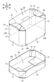
本実施形態の包装箱1は、図1に示すように、筒状に形成された胴部10と、胴部10の上側の開口部に設けられた上蓋部20と、胴部10の下側の開口部に設けられた下蓋部30と、を備えている。
As shown in FIG. 1, the
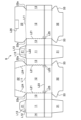
本実施形態の包装箱1は、図2に示すように、段ボール製のシートを切り抜いたブランクシートSを各折れ線において山折りまたは谷折りすることで形成される。図2に示すブランクシートSは内面側が見えるように配置されている。
ブランクシートSの折れ線は、ブランクシートSの表面を線状に押し込んで形成された罫線(押罫)である。なお、罫線に断続的な切れ込みを形成してもよい。このようにすると、折れ線においてブランクシートSを折り曲げ易くなる。
また、シートの表面のみを切断したハーフカットの切れ込みやシートを貫通した切れ込みを断続させて線状に形成することで折れ線を構成してもよい。
The
The fold lines of the blank sheet S are creases (pressed creases) formed by linearly pressing the surface of the blank sheet S. Note that intermittent cuts may be formed in the creases. In this way, it becomes easier to fold the blank sheet S at the fold lines.
Alternatively, the folded line may be formed by forming a half-cut slit only on the surface of the sheet or a slit penetrating the sheet in an intermittent linear fashion.
胴部10は、図1に示すように、前後一対の端壁11,11と、左右一対の側壁12,12と、隣り合う端壁11と側壁12との間に形成された前後左右の傾斜壁13と、を備えている。
側壁12は端壁11に対して垂直に配置され、傾斜壁13は端壁11および側壁12に対して傾斜している。本実施形態の胴部10は、平面視で八角形の筒状に形成されている(図5参照)。本実施形態の胴部10は、左右方向の長さが前後方向の長さよりも小さく形成されている。
As shown in Figure 1, the
The
端壁11および側壁12は、四角形に形成されている。本実施形態では、端壁11の左右方向の幅が側壁12の前後方向の幅がよりも小さく形成されている。また、傾斜壁13は、上下方向に細長い長方形に形成されている。
The
前側の端壁11の左縁部には、折れ線を介して左前の傾斜壁13が連設されている。
左前の傾斜壁13の左縁部(後縁部)には、折れ線を介して左側の側壁12が連設され、左側の側壁12の後縁部には、折れ線を介して左後の傾斜壁13が連設されている。
また、左後の傾斜壁13の右縁部(後縁部)には、折れ線を介して後側の端壁11が連設され、後側の端壁11の右縁部には、折れ線を介して接合片14が連設されている。
A left front
The
In addition, the
前側の端壁11の右縁部には、折れ線を介して右前の傾斜壁13が連設され、右前の傾斜壁13の右縁部(後縁部)には、折れ線を介して右側の側壁12が連設されている。
また、右側の側壁12の後縁部には、折れ線を介して右後の傾斜壁13が連設されている。右後の傾斜壁13の内面には、接合片14が接合されている。
ブランクシートS(図2参照)を各折れ線で折り曲げつつ、接合片14を右後の傾斜壁13の内面に接合すると、前後の端壁11,11、左右の側壁12,12および四つの傾斜壁13によって、平面視で八角形の筒状の胴部10が形成される(図5参照)。
A right front
A right rear
When the blank sheet S (see Figure 2) is folded at each fold line and the joining
左前の傾斜壁13と側壁12の前縁部との間の折れ線上には、第一切断誘導線L21が形成されている。本実施形態では、第一切断誘導線L21は、傾斜壁13と側壁12との間の折れ線の上側の約2/3の領域に形成されている。
第一切断誘導線L21は、切れ込みを断続的に形成したミシン目状の線である。なお、切れ込みの形状や長さは限定されるものではない。
同様に、図4に示すように、側壁12の後縁部と左後の傾斜壁13との間の折れ線上にも、第一切断誘導線L21が形成されている。さらに、図3に示すように、前側の端壁11と左前の傾斜壁13との折れ線上にも、第一切断誘導線L21が形成されている。
A first cutting guide line L21 is formed on the folded line between the left front
The first cutting guide line L21 is a perforated line formed by discontinuously forming slits. Note that the shape and length of the slits are not limited.
Similarly, as shown in Fig. 4, a first cutting guide line L21 is formed on the folded line between the rear edge of the
胴部10には、図1に示すように、第三切断誘導線L23が全周に亘って形成されている。本実施形態の第三切断誘導線L23は、胴部10の内面に貼り付けたカットテープによって構成されている。
第三切断誘導線L23のカットテープを外側に引くことで、カットテープによって端壁11、側壁12および傾斜壁13を直線状に切断できる。そして、胴部10の第三切断誘導線L23を全て切り開くことで、図8に示すように、胴部10を上下に切り離すことができる。
1, a third cutting guide line L23 is formed around the entire circumference of the
By pulling the cutting tape of the third cutting guide line L23 outward, the cutting tape can linearly cut the
第三切断誘導線L23は、各第一切断誘導線L21の下端部と同じ高さに形成されている。したがって、図3に示すように、胴部10の前部の左右の第一切断誘導線L21,L21の下端部の間には、第三切断誘導線L23が左右方向に延びている。また、図4に示すように、胴部10の左側面の前後の第一切断誘導線L21,L21の下端部の間には、第三切断誘導線L23が左右方向に延びている。
The third cutting guide line L23 is formed at the same height as the lower end of each first cutting guide line L21. Therefore, as shown in FIG. 3, the third cutting guide line L23 extends in the left-right direction between the lower ends of the first cutting guide lines L21, L21 on the left and right sides of the front of the
左側の側壁12において、第三切断誘導線L23の前後の端部に対応する位置には、スリットによって区画された側面開封開始部L25,L25が形成されている。また、図2に示すように、右側の側壁12において、第三切断誘導線L23の前端部に対応する位置にも、側面開封開始部L25が形成されている。
In the
下蓋部30は、図1に示すように、前後の端壁11,11の下縁部にそれぞれ連設された前後一対の内フラップ31,31と、左右の側壁12,12の下縁部にそれぞれ連設された左右一対の外フラップ32,32と、を備えている。
本実施形態では、図5に示すように、両内フラップ31,31の下面に両外フラップ32,32が重ねられている。内フラップ31の外面と外フラップ32の内面とは、ホットメルト等の接着剤によって接着されている。また、両外フラップ32,32の先端部は突き合わされている。このようにして、胴部10の下側の開口部が下蓋部30によって閉塞されている。
As shown in Figure 1, the
In this embodiment, as shown in Fig. 5, the two
両外フラップ32,32の前後の端部には、前後の窪み部33,33がそれぞれ形成されている。窪み部33は、両外フラップ32,32の突き合わせ部の端部を、前後方向の中央部に向けて窪ませた部位である。窪み部33内には、内フラップ31が露出している。すなわち、包装箱1の底面には、左右の窪み部33,33によって平面視台形状の凹部が形成されている。
Front and
窪み部33は、後記する上蓋部20の端部フラップ21の直下に配置されており(図1参照)、二つの包装箱1,1を上下に積み重ねたときに、上側の包装箱1の下蓋部30の窪み部33に、下側の包装箱1の上蓋部20の端部フラップ21が入り込むように構成されている。窪み部33は、端部フラップ21の形状に合わせて形成されており、端部フラップ21よりも僅かに大きく形成されている。
The recessed
上蓋部20は、図1に示すように、左右の側壁12,12の上縁部にそれぞれ連設された左右一対の側部フラップ22,22と、前後の端壁11,11の上縁部にそれぞれ連設された前後一対の端部フラップ21,21と、を備えている。
両側部フラップ22,22の先端部を突き合わせるとともに、両端部フラップ21,21を両側部フラップ22,22の外面に重ねることで、胴部10の上側の開口部が上蓋部20によって閉塞されている。
As shown in Figure 1, the
The upper opening of the
側部フラップ22には、傾斜壁13の上縁部に重なる傾斜縁部22aが形成されている。傾斜縁部22aは、傾斜壁13の外面よりも外側に突出しており、胴部10の上側の開口部の角部が確実に閉じられている。
The side flaps 22 are formed with
左側の側部フラップ22には、左右方向に延びている前後の第四切断誘導線L24,L24が形成されている。第四切断誘導線L24は、側部フラップ22の基端縁部から先端縁部に亘って形成されている。第四切断誘導線L24の基端部は、第一切断誘導線L21の上端部に接続されている。前後の第四切断誘導線L24,L24は、前後方向に間隔を空けて配置されており、その間隔は側部フラップ22の基端側から先端側に向かうに連れて小さくなっている。
右側の側部フラップ22の先端部において、左側の側部フラップ22の両第四切断誘導線L24,L24の先端部の間に対応する位置には、スリットによって区画された天面開封開始部L26が形成されている。
The
At the tip of the
側部フラップ22は、側壁12の上縁部に第一折れ線L11を介して連設されており、第一折れ線L11において側壁12に対して内側に折り曲げられている。
第一折れ線L11は、図2に示すように、側壁12と側部フラップ22との境界に形成されている。第一折れ線L11は、ブランクシートSの内面を線状に押し込んで形成された罫線(押罫)である。側壁12と側部フラップ22との境界に形成される折れ線(罫線)は、一本の第一折れ線L11のみであり、第一折れ線L11以外の折れ線は存在していない。
The
2, the first fold line L11 is formed at the boundary between the
第一折れ線L11は、側部フラップ22の先端側に向けて突出するように曲げられている。本実施形態では、第一折れ線L11全体が弧状に湾曲している。第一折れ線L11の頂点は、側壁12の前後方向の中央部に配置されている。
本実施形態では、側壁12の前後の側縁部の上端部を結んだ直線状の仮想線に対して、第一折れ線L11の頂点が4mm程度間隔を空けて配置されるように、第一折れ線L11の曲率が設定されている。
The first fold line L11 is bent so as to protrude toward the tip side of the
In this embodiment, the curvature of the first fold line L11 is set so that the apex of the first fold line L11 is positioned approximately 4 mm apart from a straight virtual line connecting the upper ends of the front and rear side edges of the
第一折れ線L11において側部フラップ22を側壁12に対して折り曲げると、図4に示すように、側壁12の上縁部(第一折れ線L11)が上方に向けて突出するように弧状に曲がった状態となる。
When the
端部フラップ21は、図1に示すように、端壁11の上縁部に第二折れ線L12を介して連設されている。
図2に示すように、第二折れ線L12は、端壁11と端部フラップ21との境界に形成されている。第二折れ線L12は、ブランクシートSの内面を線状に押し込んで形成された罫線(押罫)である。第二折れ線L12は、端壁11の左右方向に直線状に形成されている。
As shown in FIG. 1, the
2, the second fold line L12 is formed at the boundary between the
端部フラップ21の基端部には、図1に示すように、左右方向に延びている第三折れ線L13が形成されている。第三折れ線L13は、図2に示すブランクシートSの内面を線状に押し込んで形成された罫線(押罫)である。
As shown in FIG. 1, a third fold line L13 extending in the left-right direction is formed at the base end of the
第三折れ線L13は、端部フラップ21の先端側に向けて突出するように曲げられている。本実施形態では、第三折れ線L13全体が弧状に湾曲している。第三折れ線L13の頂点は、端壁11の左右方向の中央部に配置されている。また、第三折れ線L13の左右の端部は、端壁11の上縁部(第二折れ線L12)の左右の端部に向けて延びている。
なお、本実施形態では、第二折れ線L12と第三折れ線L13の頂点とが12mm程度間隔を空けて配置されるように、第三折れ線L13の曲率が設定されている。
The third fold line L13 is bent so as to protrude toward the tip side of the
In this embodiment, the curvature of the third fold line L13 is set so that the apexes of the second fold line L12 and the third fold line L13 are spaced apart by approximately 12 mm.
端部フラップ21を端壁11に対して折り曲げると、図4に示すように、端部フラップ21の基端部は、第二折れ線L12および第三折れ線L13において二段階に折れ曲がる。そして、端部フラップ21は、側部フラップ22の厚みを越えて、側部フラップ22の外面(上面)に重なる。
側部フラップ22の外面と端部フラップ21の内面とは、ホットメルト等の接着剤によって接着されている。
When the
The outer surfaces of the side flaps 22 and the inner surfaces of the end flaps 21 are bonded together with an adhesive such as hot melt.
図1に示すように、前側の端部フラップ21と前側の端壁11との間の第二折れ線L12上には第二切断誘導線L22が形成されている。このように、左右の第一切断誘導線L21,L21の上端部の間には、左右方向に延びている第二切断誘導線L22が形成されている。
第二切断誘導線L22は、切れ込みを断続的に形成したミシン目状の線である。なお、切れ込みの形状や長さは限定されるものではない。
1, a second cutting guide line L22 is formed on the second fold line L12 between the
The second cutting guide line L22 is a perforated line formed by discontinuously forming slits. Note that the shape and length of the slits are not limited.
本実施形態の包装箱1における第一の開封形態では、図6に示すように、胴部10の前部において、左右の第一切断誘導線L21,L21、第二切断誘導線L22および第三切断誘導線L23を切り開き、端壁11および左右の傾斜壁13,13の上部を切り取る。これにより、胴部10の前部(前側の端壁11側)に開口部を形成できる。
In the first opening form of the
本実施形態の包装箱1における第二の開封形態では、図7に示すように、左側の側壁12の第三切断誘導線L23を切り開いた後に、左側の側部フラップ22の両第四切断誘導線L24,L24の間の領域を先端側から引き上げて、両第四切断誘導線L24,L24を切り開く。さらに、両第四切断誘導線L24,L24に続いて、左側の側壁12の両第一切断誘導線L21,L21を切り開く。このようにして、左側の側部フラップ22の中央部および左側の側壁12の上部を切り取ることで、胴部10の側部(左側の側壁12側)に開口部を形成できる。
In the second opening form of the
本実施形態の包装箱1における第三の開封形態では、図8に示すように、胴部10の第三切断誘導線L23を全周に亘って切り開くことで、胴部10を上下に分離させ、包装箱1の上部を下部から切り取って開封する。このように包装箱1を開封すると、包装箱1の下部はトレイとなるため、内容物をトレイに収容した状態で陳列できる。
In the third opening form of the
以上のような包装箱1では、図2に示すように、側壁12と側部フラップ22との間の第一折れ線L11が、側部フラップ22の先端側に向けて突出するように弧状に曲げられている。このようにすると、図1に示すように、側壁12に対して側部フラップ22を綺麗に折り曲げつつ、側部フラップ22の復元力が大きくなる。
これにより、側部フラップ22は外側に向けて浮き上がろうとするため、側部フラップ22が胴部10の内部に入り込むのを防ぐことができる。
そして、本実施形態の包装箱1では、側部フラップ22の外面が端部フラップ21の内面に押し付けられる。この結果、側部フラップ22の外面に端部フラップ21を接着剤によって接着し易くなり、上蓋部20を確実に閉じることができる。
また、側部フラップ22が胴部10の内部に入り込むのを防ぐことにより、側部フラップ22に重ねた端部フラップ21も上蓋部20の外面から盛り上がる。これにより、図5に示すように、二つの包装箱1,1を上下に重ねたときに、下側の包装箱1の上蓋部20の端部フラップ21を、上側の包装箱1の下蓋部30の窪み部33に入り込ませて、下側の包装箱1に対して上側の包装箱1がずれるのを防ぐことができ、包装箱1を安定して積み重ねることができる。
In the above-described
This causes the side flaps 22 to tend to rise outward, thereby preventing the side flaps 22 from penetrating into the
In the
In addition, by preventing the side flaps 22 from entering the inside of the
また、本実施形態の包装箱1では、端壁11に対して端部フラップ21を折り曲げたときに、端部フラップ21の基端部が第二折れ線L12および第三折れ線L13において二段階に折れ曲がる。これにより、端部フラップ21を側部フラップ22の厚みを越えて側部フラップ22の外面に重ね易くなる。
In addition, in the
また、本実施形態の包装箱1では、端部フラップ21の基端部に形成された第三折れ線L13が、端部フラップ21の先端側に向けて突出するように弧状に曲げられている。このようにすると、端壁11に対して端部フラップ21を折り曲げたときに、端部フラップ21の復元力が大きくなり、端部フラップ21が上蓋部20の外面から盛り上がる。
これにより、図5に示すように、二つの包装箱1,1を上下に重ねたときに、下側の包装箱1の上蓋部20の端部フラップ21を、上側の包装箱1の下蓋部30の窪み部33に入り込ませて、下側の包装箱1に対して上側の包装箱1がずれるのを防ぐことができ、包装箱1を安定して積み重ねることができる。
In the
As a result, as shown in Figure 5, when two
本実施形態の包装箱1は、図1に示すように、胴部10の左右方向の長さが前後方向の長さよりも小さいため、端壁11を陳列スペースの正面に向けて配置することで、包装箱1の陳列スペースを確保し易い。
そして、図6に示すように、胴部10の前部の両第一切断誘導線L21,L21、第二切断誘導線L22および第三切断誘導線L23を切り開いて、胴部10から端壁11および左右の傾斜壁13,13を切り取ることで、胴部10の前部に開口部を形成できる。
したがって、本実施形態の包装箱1では、陳列スペースを確保し易くしつつ、陳列スペースの正面に向いた開口部を大きく形成して、内容物を露出させるとともに、内容物を取り出し易くなる。
As shown in FIG. 1, in the
Then, as shown in Figure 6, by cutting open the first cutting guide lines L21, L21, the second cutting guide line L22 and the third cutting guide line L23 at the front of the
Therefore, in the
以上、本発明の実施形態について説明したが、本発明は前記実施形態に限定されることなく、その趣旨を逸脱しない範囲で適宜に変更が可能である。
例えば、図1に示す本実施形態の包装箱1における上蓋部20の構成を、下蓋部30に適用してもよい。
Although the embodiment of the present invention has been described above, the present invention is not limited to the above embodiment, and can be appropriately modified without departing from the spirit of the present invention.
For example, the configuration of the
本実施形態の包装箱1では、上蓋部20に前後の端部フラップ21,21が設けられているが、上蓋部20を左右の側部フラップ22,22のみによって構成し、両側部フラップ22,22の先端部を粘着テープによって固定してもよい。
In the
本実施形態の包装箱1の胴部10は、八角形に形成されているが、胴部10の形状は限定されるものではない。例えば、二つの傾斜壁13,13を一方の対角となる位置のみに配置して胴部10を六角形に形成したり、傾斜壁13を設けることなく、胴部10を四角形に形成したりしてもよい。
The
本実施形態の包装箱1には、複数の切断誘導線が形成されており、複数の形態で開封できるように構成されているが、切断誘導線の位置や本数は限定されるものではなく、内容物の大きさや形状に応じて適宜に設定できる。例えば、第一切断誘導線を端壁11と傾斜壁13との間に形成してもよい。更には、包装箱1に開封用の切断誘導線を形成しなくてもよい。
The
本実施形態の第三切断誘導線L23は、カットテープによって構成されているが、第三切断誘導線L23を、ミシン目やジッパーによって構成してもよい。
本実施形態の第一切断誘導線L21および第二切断誘導線L22は、折れ線(罫線)上に形成されているが、罫線を形成することなく、ミシン目である第一切断誘導線L21および第二切断誘導線L22が折れ線を兼ねるように構成してもよい。
In the present embodiment, the third cutting guide line L23 is formed by a cut tape, but the third cutting guide line L23 may be formed by a perforation or a zipper.
In this embodiment, the first cutting guide line L21 and the second cutting guide line L22 are formed on a folded line (ruled line), but the first cutting guide line L21 and the second cutting guide line L22, which are perforations, may also serve as a folded line without forming a ruled line.
本実施形態の包装箱1は、段ボール製であるが、各種公知の板紙によって包装箱を形成できる。
The
1 包装箱
10 胴部
11 端壁
12 側壁
13 傾斜壁
14 接合片
20 上蓋部
21 端部フラップ
22 側部フラップ
22a 傾斜縁部
30 下蓋部
31 内フラップ
32 外フラップ
33 窪み部
L11 第一折れ線
L12 第二折れ線
L13 第三折れ線
L21 第一切断誘導線
L22 第二切断誘導線
L23 第三切断誘導線
L24 第四切断誘導線
L25 側面開封開始部
L26 天面開封開始部
S ブランクシート
REFERENCE SIGNS
Claims (5)
前記胴部の上下方向の開口部に設けられた蓋部と、を備え、
前記蓋部は、
前記側壁の上下方向の縁部に第一折れ線を介して連設された側部フラップを有し、
前記第一折れ線は、前記側部フラップの先端側に向けて突出するように曲げられていることを特徴とする包装箱。 A cylindrical body portion having front and rear end walls and left and right side walls;
A lid portion provided on an opening in the vertical direction of the body portion,
The lid portion is
A side flap is provided at an edge of the side wall in the vertical direction via a first fold line,
The packaging box is characterized in that the first fold line is bent so as to protrude toward the tip side of the side flap.
前記第一折れ線全体が弧状に湾曲していることを特徴とする包装箱。 The packaging box according to claim 1,
The packaging box is characterized in that the entire first fold line is curved in an arc shape.
前記胴部の上側の開口部に設けられた上蓋部と、
前記胴部の下側の開口部に設けられた下蓋部と、を備え、
前記上蓋部は、
前記側壁の上縁部に第一折れ線を介して連設された側部フラップと、
前記端壁の上縁部に第二折れ線を介して連設された端部フラップと、を有し、
前記端部フラップの基端部には、左右方向に延びている第三折れ線が形成され、
前記第三折れ線は、前記端部フラップの先端側に向けて突出するように曲げられており、
前記下蓋部において、前記端部フラップの直下となる領域には、窪み部が形成されていることを特徴とする包装箱。 A cylindrical body portion having front and rear end walls and left and right side walls;
An upper cover portion provided at an upper opening of the body portion;
A lower lid portion provided at an opening on the lower side of the body portion,
The upper cover portion is
A side flap connected to an upper edge of the side wall via a first fold line;
an end flap connected to an upper edge of the end wall via a second fold line;
A third fold line extending in the left-right direction is formed at the base end of the end flap,
The third fold line is bent so as to protrude toward a tip side of the end flap,
A packaging box, characterized in that a recess is formed in the lower lid portion in an area directly below the end flap.
前記胴部の上下の開口部に設けられた上下の蓋部と、を備え、
前記胴部は、左右方向の長さが前後方向の長さよりも小さく形成されており、
前記端壁と前記両側壁との間には、上下方向に延びている左右の第一切断誘導線が形成され、
前記両第一切断誘導線の上端部の間には、左右方向に延びている第二切断誘導線が形成され、
前記両第一切断誘導線の下端部の間には、左右方向に延びている第三切断誘導線が形成されており、
前記両第一切断誘導線、前記第二切断誘導線および前記第三切断誘導線を切り開いて、前記胴部の端壁側に開口部を形成可能であることを特徴とする包装箱。 A cylindrical body portion having front and rear end walls and left and right side walls;
and upper and lower lids provided on the upper and lower openings of the body,
The body portion is formed such that the length in the left-right direction is smaller than the length in the front-rear direction,
Between the end wall and the two side walls, left and right first cutting guide lines are formed extending in the vertical direction,
A second cutting guide line is formed between the upper ends of the first cutting guide lines and extends in the left-right direction.
A third cutting guide line is formed between the lower ends of the first cutting guide lines and extends in the left-right direction,
A packaging box, characterized in that an opening can be formed on an end wall side of the body portion by cutting open the first cutting guide wires, the second cutting guide wire, and the third cutting guide wire.
前記端壁と前記側壁との間に傾斜壁が形成されており、
前記第一切断誘導線は、前記傾斜壁と前記側壁との間に形成されていることを特徴とする包装箱。 The packaging box according to claim 4,
A sloped wall is formed between the end wall and the side wall,
The packaging box according to claim 1, wherein the first cutting guide line is formed between the inclined wall and the side wall.
Priority Applications (1)
| Application Number | Priority Date | Filing Date | Title |
|---|---|---|---|
| JP2023077259A JP2024162076A (en) | 2023-05-09 | 2023-05-09 | Packaging box |
Applications Claiming Priority (1)
| Application Number | Priority Date | Filing Date | Title |
|---|---|---|---|
| JP2023077259A JP2024162076A (en) | 2023-05-09 | 2023-05-09 | Packaging box |
Publications (1)
| Publication Number | Publication Date |
|---|---|
| JP2024162076A true JP2024162076A (en) | 2024-11-21 |
Family
ID=93522664
Family Applications (1)
| Application Number | Title | Priority Date | Filing Date |
|---|---|---|---|
| JP2023077259A Pending JP2024162076A (en) | 2023-05-09 | 2023-05-09 | Packaging box |
Country Status (1)
| Country | Link |
|---|---|
| JP (1) | JP2024162076A (en) |
Citations (2)
| Publication number | Priority date | Publication date | Assignee | Title |
|---|---|---|---|---|
| JP2007039090A (en) * | 2005-08-04 | 2007-02-15 | Rengo Co Ltd | Cardboard packaging box |
| JP2017052529A (en) * | 2015-09-08 | 2017-03-16 | 大和紙器株式会社 | Outer packaging corrugated box of bag-in-box |
-
2023
- 2023-05-09 JP JP2023077259A patent/JP2024162076A/en active Pending
Patent Citations (2)
| Publication number | Priority date | Publication date | Assignee | Title |
|---|---|---|---|---|
| JP2007039090A (en) * | 2005-08-04 | 2007-02-15 | Rengo Co Ltd | Cardboard packaging box |
| JP2017052529A (en) * | 2015-09-08 | 2017-03-16 | 大和紙器株式会社 | Outer packaging corrugated box of bag-in-box |
Similar Documents
| Publication | Publication Date | Title |
|---|---|---|
| CN101384490B (en) | Curved cigarette pack flap arrangement on curved surfaces | |
| JP6503883B2 (en) | Packaging box | |
| JP7242474B2 (en) | packaging box | |
| JP7081988B2 (en) | Packaging box | |
| JP6926766B2 (en) | Packaging box | |
| JP2019077466A (en) | Packaging box | |
| JP7542938B2 (en) | Packaging box | |
| JP2022179020A (en) | Packing box | |
| JP7501382B2 (en) | Packaging box | |
| JP7743810B2 (en) | packaging box | |
| JP7415906B2 (en) | Packaging boxes and how to assemble packaging boxes | |
| JP2022061198A (en) | Packing box | |
| JP7677205B2 (en) | packaging box | |
| JP7683429B2 (en) | packaging box | |
| JP7633765B2 (en) | Packaging box | |
| JP7192517B2 (en) | packaging box | |
| JP7743817B2 (en) | packaging box | |
| JP7574768B2 (en) | Packaging box | |
| JP7380457B2 (en) | blank sheet | |
| JP7409989B2 (en) | packaging box | |
| JP7463770B2 (en) | Packaging box | |
| JP7501397B2 (en) | Packaging box | |
| JPH0723386Y2 (en) | Split type packaging box | |
| JP7475878B2 (en) | Packaging box | |
| JP2025088606A (en) | Blank sheet, pre-formed box, packaging box, and method for manufacturing pre-formed box using the blank sheet |
Legal Events
| Date | Code | Title | Description |
|---|---|---|---|
| A621 | Written request for application examination |
Free format text: JAPANESE INTERMEDIATE CODE: A621 Effective date: 20250714 |
|
| A977 | Report on retrieval |
Free format text: JAPANESE INTERMEDIATE CODE: A971007 Effective date: 20260423 |
|
| A131 | Notification of reasons for refusal |
Free format text: JAPANESE INTERMEDIATE CODE: A131 Effective date: 20260428 |
|
| A521 | Request for written amendment filed |
Free format text: JAPANESE INTERMEDIATE CODE: A523 Effective date: 20260527 |