JP2023167405A - ventilation structure - Google Patents
ventilation structure Download PDFInfo
- Publication number
- JP2023167405A JP2023167405A JP2022078572A JP2022078572A JP2023167405A JP 2023167405 A JP2023167405 A JP 2023167405A JP 2022078572 A JP2022078572 A JP 2022078572A JP 2022078572 A JP2022078572 A JP 2022078572A JP 2023167405 A JP2023167405 A JP 2023167405A
- Authority
- JP
- Japan
- Prior art keywords
- ventilation
- ridge
- roof
- wrapper
- air
- Prior art date
- Legal status (The legal status is an assumption and is not a legal conclusion. Google has not performed a legal analysis and makes no representation as to the accuracy of the status listed.)
- Pending
Links
Images


Landscapes
- Roof Covering Using Slabs Or Stiff Sheets (AREA)
Abstract
Description
本発明は、屋根面に平行状に設けた換気棟面に形成した複数の通気孔から空気を吸い出すことにより、建築高さを過剰に増大させることなく、一般住宅等の屋根棟に設けられて室内の換気を確実に行うことができる換気構造に関する。 The present invention allows air to be sucked out from a plurality of ventilation holes formed in the ventilation ridge surface provided parallel to the roof surface, thereby eliminating the need to excessively increase the building height. This invention relates to a ventilation structure that can ensure indoor ventilation.
建築物の棟部に設けられる換気装置は、外気から新鮮な空気を導入すると共に、室内空間にて温められた空気を室外へ排出するものであるが、降雨等に際して雨水の浸入を極力避けることが要求される。
多くの従来の換気装置は、側方からの空気の取り込みを行うために棟部に、高さ方向に形成した傾斜面に複数の導入口を設けるか、高さ寸法を有する側面に導入口を設け、側方からの空気を取り入れる構造が知られている。即ち側方や斜め側方からの風(=吹き付け風)に導入口を正対させる目的で、該導入口を傾斜面や側面に形成した構造が採用されている。
Ventilation systems installed in the ridges of buildings are designed to bring in fresh air from outside and exhaust air that has been warmed in the indoor space to the outside, but it is important to avoid rainwater intrusion as much as possible in the event of rain, etc. is required.
In many conventional ventilation systems, in order to take in air from the sides, multiple inlets are provided in the ridge, on a sloped surface formed in the height direction, or inlet ports are provided in the side surface that has a height dimension. A structure is known in which air is taken in from the sides. That is, a structure is adopted in which the inlet is formed on an inclined surface or side surface in order to directly face the wind (=blown wind) from the side or diagonal side.
例えば特許文献1などに記載される換気装置では、比較的高さ厚みを大きく形成して側面(側方)からの風(空気)を導入させると共に、換気棟の内部構造に門型部換気口や山形部換気口や屈曲部換気口などが設けられ、流れ方向(勾配方向)の風雨の侵入経路を複雑にすることで雨の吹き込みを防止しているものである。
For example, in the ventilation system described in
しかしながら、前記特許文献1の換気装置では、高さ方向の寸法を大きくする必要があるため、特に一般住宅等には適用し難いという問題があった。即ち一般住宅では、日照権等の問題があるため、高さ寸法を大きくすることには制限があった。
しかも、比較的高く形成した傾斜面や側面に導入口を設け、外気の新鮮な空気を導入しようとしても、内部への導入も外部への排気も充分ではないために、換気が充分に行われないという問題を生ずるものであった。
However, the ventilation device of
Moreover, even if you try to introduce fresh air from the outside by installing an inlet on a relatively high inclined surface or side, there is not enough air being brought inside or exhausted to the outside, making it difficult to properly ventilate the air. This caused the problem that there was no such thing.
そこで、本発明は、屋根面に平行状に設けた換気棟面に形成した複数の通気孔から空気を吸い出すことにより、建築高さを過剰に増大させることなく、一般住宅等の屋根棟に設けられて室内の換気を確実に行うことができる換気構造を提案することを目的とする。 Therefore, the present invention has been developed to suck out air from a plurality of ventilation holes formed in the ventilation ridge surface provided parallel to the roof surface, thereby eliminating the need to excessively increase the building height. The purpose of this study is to propose a ventilation structure that can reliably ventilate the room.
本発明は、上記に鑑み提案されたもので、屋根棟に設けられる開放部に対して配設する、棟下地と、該棟下地に固定される換気棟フレームと、該換気棟フレームに裏面側から支持される換気棟包みと、からなる換気構造であって、換気棟包みと屋根面との間には、排水用の空間が設けられ、前記換気棟包みには、複数の通気孔が設けられ、該通気孔が上向きルーバー形状に形成されていることを特徴とする換気構造に関するものである。
なお、屋根棟に設けられる開放部とは、建築物の内部空間に連通する開口部分の上端を指すものであって、前記棟下地の上端の開口部分と連通する下方にこの開放部は位置している。また、ルーバーとは、羽板を並行状に並べて日光や風雨を遮断することができる日よけや雨よけに用いられ、上向きルーバー形状とは、先端が傾斜状に突き出している形状を指している。
The present invention has been proposed in view of the above, and includes a roof ridge base, a ventilation ridge frame fixed to the ridge base, and a back side of the ventilation ridge frame. A ventilation structure consisting of a ventilation ridge wrapper supported by the ventilation ridge wrapper, and a drainage space provided between the ventilation ridge wrapper and the roof surface, and a plurality of ventilation holes provided in the ventilation ridge wrapper. The present invention relates to a ventilation structure characterized in that the ventilation hole is formed in an upward louver shape.
Note that the open part provided in the roof ridge refers to the upper end of the opening part that communicates with the internal space of the building, and this open part is located at the lower part that communicates with the opening part at the upper end of the ridge base. ing. In addition, louvers are used for sunshades and rain shelters by arranging the blades in parallel to block sunlight, wind and rain, and the upward louver shape refers to the shape with the tip protruding in an inclined manner. .
また、本発明は、前記換気構造において、前記開放部への雨水の浸入が阻止される遮水壁部が、前記換気棟フレームに設けられていることを特徴とする換気構造をも提案する。 The present invention also proposes the ventilation structure, characterized in that the ventilation ridge frame is provided with an impermeable wall portion that prevents rainwater from entering the open portion.
また、本発明は、前記換気構造において、前記開放部への雨水の浸入が阻止される気密材(モヘア)が、前記換気棟包みの裏面側に設けられていることを特徴とする換気構造をも提案する。 Further, the present invention provides the ventilation structure, wherein an airtight material (mohair) that prevents rainwater from entering the open portion is provided on the back side of the ventilation ridge wrapper. I also suggest.
本発明の換気構造は、屋根棟に設けられる開放部に対して配設する、棟下地と、該棟下地に固定される換気棟フレームと、該換気棟フレームに裏面側から支持される換気棟包みと、からなり、換気棟包みと屋根面との間には、排水用の空間が設けられ、換気棟包みには、複数の通気孔が設けられ、該通気孔が上向きルーバー形状に形成されている。そのため、室内側の空気が、複数の通気孔から吸い出される構造であって、建築高さを過剰に増大させることなく、一般住宅等の屋根棟に設けられて室内の換気を確実に行うことができる。即ち換気棟包みには、屋根面に平行状に換気棟面が形成され、該換気棟面に複数の通気孔が形成されるため、それぞれの上向きルーバーに吹き上げ風が当たることにより、内部空気の吸い出し作用が果たされる。 The ventilation structure of the present invention includes a roof ridge base, a ventilation ridge frame fixed to the ridge base, and a ventilation ridge frame supported by the ventilation ridge frame from the back side, which are arranged for an open part provided in a roof ridge. A space for drainage is provided between the ventilation ridge wrapping and the roof surface, and a plurality of ventilation holes are provided in the ventilation ridge wrapping, and the ventilation holes are formed in an upward louver shape. ing. Therefore, the structure is such that the air inside the room is sucked out through multiple ventilation holes, and it is installed in the roof ridge of a general residence, etc. to ensure indoor ventilation without increasing the building height excessively. I can do it. In other words, in the ventilation ridge wrapper, a ventilation ridge surface is formed parallel to the roof surface, and a plurality of ventilation holes are formed on the ventilation ridge surface, so that the internal air is blown up by hitting each upward louver. A suction action is performed.
また、前記開放部への雨水の浸入が阻止される遮水壁部が、換気棟フレームに設けられている場合には、仮に排水用の空間から吹き上げ風に混じって換気棟包みの内部に雨水が浸入しても、また仮に通気孔から雨水が浸入しても、遮水壁部にて流下させるために、開放部からの雨水の侵入は確実に阻止される。 In addition, if the ventilation ridge frame is provided with an impermeable wall that prevents rainwater from entering the open area, if the rainwater mixes with the wind blowing up from the drainage space and flows inside the ventilation ridge wrapper, Even if rainwater intrudes through the ventilation hole, the rainwater is reliably prevented from entering through the open part because it flows down through the impermeable wall part.
また、前記開放部への雨水の浸入が阻止される気密材が、換気棟包みの裏面側に設けられている場合には、通気孔から吸い込まれた雨水や水分を含んだ空気が気密材と接触することで、霧散状となることを防止して垂下状に落下させることができる。 In addition, if an airtight material that prevents rainwater from entering the open portion is provided on the back side of the ventilation ridge wrapper, rainwater and moisture-laden air sucked in through the ventilation holes may enter the airtight material. By contacting it, it is possible to prevent it from becoming atomized and to make it fall in a drooping manner.
本発明の換気構造は、屋根棟に設けられる開放部に対して配設する、棟下地と、該棟下地に固定される換気棟フレームと、該換気棟フレームに裏面側から支持される換気棟包みと、からなり、換気棟包みと屋根面との間には、排水用の空間が設けられ、前記換気棟包みには、複数の通気孔が設けられ、該通気孔が上向きルーバー形状に形成されていることを特徴とする。 The ventilation structure of the present invention includes a roof ridge base, a ventilation ridge frame fixed to the ridge base, and a ventilation ridge frame supported by the ventilation ridge frame from the back side, which are arranged for an open part provided in a roof ridge. A space for drainage is provided between the ventilation ridge wrapping and the roof surface, and a plurality of ventilation holes are provided in the ventilation ridge wrapping, and the ventilation holes are formed in an upward louver shape. It is characterized by being
建物の屋根裏空間を含む室内の空気を換気する構造とは、室内側の空気を室外へ排出する「排出」と、室外側の空気を室内へ導入する「導入」とが、同時に行われなければならない。
例えば電動ファン等を用いて強制的に室内側の空気を排出し、それにより室外側の空気を導入しようとする方法があるが、この方法では、電動ファンを稼働させる電源の確保や電気ケーブル等を必要とするし、漏電等の観点からも到底採用できない。
室外の空気を導入しやすくする目的で、前述の従来の技術にて説明したように、吹き込み風に正対させるように導入口を設け、該導入口から外気を導入しようする方法がある。この方法は、側方からの風を直接的に導入しようとするものであるが、充分に換気を行うことができず、導入口を大きくする目的で高さ寸法を大きくすることにも制限があった。これは、導入口の大きさに制限があるし、そもそも室内側の空気の方が圧力が高いことも要因と考えられる。
A structure that ventilates indoor air, including the attic space of a building, requires that ``exhaust'', which exhausts indoor air to the outside, and ``induction'', which introduces outside air into the room, are performed at the same time. No.
For example, there is a method of forcibly exhausting the indoor air using an electric fan, etc., and thereby introducing air from the outdoor side. However, this method requires a power source to operate the electric fan, an electric cable, etc. , and it cannot be adopted at all from the viewpoint of electric leakage, etc.
In order to facilitate the introduction of outdoor air, there is a method of providing an inlet so as to directly face the blown wind and introducing the outside air through the inlet, as explained in the prior art section. This method attempts to directly introduce wind from the sides, but it does not allow for sufficient ventilation, and there are also restrictions on increasing the height dimension for the purpose of enlarging the introduction port. there were. This is thought to be due to the fact that there is a limit to the size of the inlet, and the pressure of the air inside the room is higher in the first place.
それに対し、本発明の換気構造は、複数の通気孔の上向きルーバーに建物を伝う吹き上げ風が当たることにより、各通気孔の上方に減圧空間が形成され、室内の空気の吸い出し作用が果たされ、室内側の空気が室外側へ排気される。しかも、このような複数の換気孔を、屋根面に平行状に配設する換気面部に形成することで、一般住宅等の屋根棟でも建築高さを過剰に増大させることなく、室内の換気を確実に行うことができる。
なお、換気構造の中でも、室内で暖められた空気は、より高い頂部付近に対流しようとするが、本発明の換気構造では、この頂部付近に通気孔が設けられるので、排気作用が高いものとなる。そのため、側面部に形成した孔からの吹き込み風の導入作用も、前記従来の技術よりも大きく期待できる。
In contrast, in the ventilation structure of the present invention, when the upward louvers of the plurality of ventilation holes are hit by the upward wind flowing through the building, a depressurized space is formed above each ventilation hole, and the indoor air is sucked out. , the air inside the room is exhausted to the outside. Moreover, by forming such multiple ventilation holes in the ventilation surface that is arranged parallel to the roof surface, indoor ventilation can be achieved without excessively increasing the building height even in the roof structure of a general residential building. It can be done reliably.
Note that even in a ventilation structure, air that is warmed indoors tends to convect near the top, which is higher, but in the ventilation structure of the present invention, ventilation holes are provided near this top, so the exhaust effect is high. Become. Therefore, the effect of introducing air from the holes formed in the side surface can be expected to be greater than in the conventional technology.
一方、換気に際し、室内への雨水等の浸入は防止しなければならないが、雨水等は重力にて通気孔から浸入するし、それに加え、室外側からの空気が該通気孔から内部に導入されることも想定される。
なお、通気孔からの雨水の浸入については否定できないが、前述のように当該通気孔からは室内側の空気が吸い出されているので、空気の逆流(室外側からの導入)のような現象はほとんど生じない。
そして、通気孔から浸入した雨水は、重力にて換気棟包みの裏面側の換気棟フレーム上を流れ、換気棟包みと屋根面との間に設けられた排水用の空間より排出され、屋根面上を流下される。
On the other hand, when ventilating, it is necessary to prevent rainwater from entering the room, but rainwater enters through the ventilation holes due to gravity, and in addition, air from outside the room is introduced into the interior through the ventilation holes. It is also assumed that
Although it cannot be denied that rainwater enters through the ventilation holes, as mentioned above, the air inside the room is sucked out from the ventilation holes, so there is a phenomenon like air backflow (introduction from the outside). rarely occurs.
Rainwater that has entered through the ventilation holes flows by gravity over the ventilation ridge frame on the back side of the ventilation ridge wrapper, is drained from the drainage space provided between the ventilation ridge wrapper and the roof surface, and is discharged from the roof surface. flowing down above.
本発明の換気構造を適用する屋根棟としては、棟頂部に開放部を有するものであれば屋根自体については何ら限定するものではなく、瓦、スレート、金属等の公知の屋根であっても、その仕様を問うものではない。また、屋根形式についても、横葺き状、縦葺き(瓦棒葺き、平滑状等)、折板等の如何なるものであってもよい。 The roof ridge to which the ventilation structure of the present invention is applied is not limited in any way as long as it has an open part at the top of the ridge, and even if it is a known roof made of tiles, slate, metal, etc. It does not question the specifications. Furthermore, the roof type may be of any type, such as horizontal roofing, vertical roofing (tile roofing, smooth roofing, etc.), folded plate roofing, etc.
本発明の換気構造を形成する棟下地、換気棟フレーム、換気棟包みについて、以下にその順で説明する。なお、これらの各部材を構成する素材としては、特に限定しないが、前記屋根材と同様の素材を用いることが望ましく、例えば各種の金属板材を加工して成形すればよい。 The ridge base, ventilation ridge frame, and ventilation ridge wrapper that form the ventilation structure of the present invention will be explained below in that order. Note that the materials constituting each of these members are not particularly limited, but it is desirable to use the same materials as the roofing material, and for example, they may be formed by processing various metal plate materials.
棟下地は、前述のように屋根棟に設けられる開放部に対して配設される部材であって、この棟下地と屋根面との間には、内部にて結露した水分や雨水を排水するための隙間が設けられることが望ましい。
なお、屋根棟に設けられる開放部とは、建築物の内部空間に連通する開口部分の上端を指すものであって、前記棟下地の上端の開口部分と連通する下方にこの開放部は位置している。
As mentioned above, the ridge base is a member installed for the open part provided in the roof ridge, and there is a space between this ridge base and the roof surface to drain moisture and rainwater that has condensed inside. It is desirable to provide a gap for this purpose.
Note that the open part provided in the roof ridge refers to the upper end of the opening part that communicates with the internal space of the building, and this open part is located at the lower part that communicates with the opening part at the upper end of the ridge base. ing.
この棟下地は、屋根面への凹状固定部と、該凹状固定部の水上端が立ち上がって水上側へ延在する上方固定部と、前記凹状固定部の水下端が立ち上がって水下側へ延在する下方固定部とを備えている。なお、前記凹状固定部の底部(固定面部)には、屋根下地に達する固着具を打ち込んで当該棟下地を固定するが、この固着具からの雨水の浸透を防止する止水材を介して固定されていることが望ましい。 This ridge base has a concave fixing part to the roof surface, an upper fixing part in which the upper end of the concave fixing part rises and extends to the water side, and a lower end of the concave fixing part to rise and extends to the water below. and a lower fixing part. In addition, a fixing tool that reaches the roof base is driven into the bottom (fixing surface part) of the concave fixing part to fix the roof base, but it is fixed through a water-stopping material that prevents rainwater from penetrating through this fixing tool. It is desirable that the
換気棟フレームは、前述のように前記棟下地に固定されると共に、換気棟包みを裏面側から支持される部材である。
この換気棟フレームは、前記棟下地の上方固定部及び下方固定部に支持される覆い面部と、該覆い面部の水上端が立ち上がって水上側へ延在する上方支持部と、前記覆い面部の水下端が立ち上がる下方支持部とを備えている。前記覆い面部は、その水上部分が前記棟下地の上方固定部に支持され、その水下部分が前記棟下地の下方固定部に支持され、その間の部分が前記底部(固定面部)の上方を覆っている。
The ventilation ridge frame is a member that is fixed to the ridge foundation as described above and supports the ventilation ridge wrapper from the back side.
This ventilation ridge frame includes a covering surface part supported by an upper fixed part and a lower fixed part of the ridge foundation, an upper supporting part in which the water-above end of the covering surface part stands up and extends above the water, and a water-receiving part of the covering surface part. It includes a lower support part whose lower end stands up. The above-mentioned covering surface part has an above-water part supported by an upper fixing part of the ridge base, a below-water part supported by a lower fixing part of the ridge base, and a part between them covering the upper part of the bottom part (fixed surface part). ing.
換気棟包みは、前述のように前記換気棟フレームに裏面側から支持されると共に、複数の通気孔が設けられ、該通気孔が上向きルーバー形状に形成されている部材であり、この換気棟包みと屋根面との間には、排水用の空間が設けられている。
後述する図示実施例における換気棟包みは、屋根面に平行状に配設される換気面部と、該換気面部の水下端を下向きに延在させた側面部とを備えているが、前記通気孔は、換気面部に形成されている。なお、側面部にも形状的には同一の孔が形成されているが、前述の空気の吸い出し作用は、換気面部に形成した通気孔により果たされ、側面部に形成した孔には、むしろ外部空気の導入作用が果たされる。
また、換気面部は、前記換気棟フレームの上方支持部に裏面側から支持され、側面部は、前記換気棟フレームの下方支持部に裏面側から支持されている。
As mentioned above, the ventilation ridge wrapper is a member that is supported by the ventilation ridge frame from the back side and is provided with a plurality of ventilation holes, each of which is formed in an upward louver shape. A drainage space is provided between the roof and the roof surface.
The ventilation ridge wrapper in the illustrated embodiment, which will be described later, includes a ventilation surface section disposed parallel to the roof surface, and a side surface section in which the lower end of the ventilation surface section extends downward. is formed on the ventilation surface. Note that holes with the same shape are formed on the side surface, but the air suction effect described above is achieved by the ventilation hole formed on the ventilation surface, and the hole formed on the side surface has a similar shape. The function of introducing external air is fulfilled.
Further, the ventilation surface part is supported from the back side by the upper support part of the ventilation ridge frame, and the side part is supported by the lower support part of the ventilation ridge frame from the back side.
前記排水用の空間は、内部に浸入した雨水や結露水が排出される排出口であるから、後述する図示実施例のように側面部の下端と屋根面との隙間でもよいし、側面部の下端の一部が屋根面に当接しても一部が離反していればよい。この排水用の空間には、前記側面部における孔と同様に外部空気の導入作用が期待される。 The drainage space is an outlet through which rainwater or condensation water that has entered the interior is discharged, so it may be a gap between the lower end of the side surface and the roof surface as in the illustrated embodiment described later, or a space between the lower end of the side surface and the roof surface. Even if a part of the lower end contacts the roof surface, it is sufficient that part of the lower end is separated from the roof surface. This drainage space is expected to have the same effect of introducing external air as the holes in the side surface.
前記換気面部における通気孔は、傾斜方向に複数段、長さ方向に複数列が形成され、例えば後述する図示実施例では傾斜方向に3段、長さ方向に16列の通気孔が上向きルーバー形状に形成されている。
この上向きルーバー形状とは、前述のように先端が傾斜状に突き出している形状であって、該傾斜部分に、建築物を伝う吹き上げ風が当たることにより、各傾斜部分の上方に減圧空間が形成され、空気の吸い出し作用が果たされる。
そのため、もしも仮にこのような上向きルーバー形状を備えない単なる貫通孔であったとしたら、最も高い位置に形成されている点での空気の排出は認められるが、単なる貫通孔では前述の空気の吸い出し作用が果たされないので、到底充分な換気が行われない。
この通気孔の成形は、例えば金属板のような素材を原料とすると、U字状の切り込みを形成する加工を行うと共に切り込み内部を上方へ立ち上げる加工を施すことにより、容易に形成できる。
The ventilation holes in the ventilation surface portion are formed in multiple stages in the inclination direction and in multiple rows in the length direction. For example, in the illustrated embodiment described later, the ventilation holes in 3 stages in the inclination direction and 16 rows in the length direction are formed in an upward louver shape. is formed.
This upward louver shape is a shape in which the tip protrudes in an inclined manner as mentioned above, and when the upward wind traveling through the building hits the inclined part, a depressurized space is formed above each inclined part. The air is sucked out and the air is sucked out.
Therefore, if it were a simple through hole without such an upward louver shape, air would be discharged at the highest point, but if it were a simple through hole, it would not have the air suction effect described above. Because this is not done, sufficient ventilation cannot be achieved.
For example, when a material such as a metal plate is used as a raw material, the ventilation hole can be easily formed by forming a U-shaped notch and then raising the inside of the notch upward.
そして、換気面部に形成された通気孔には、内部空気の吸い出し作用(排出作用)が果たされるが、側面部に形成された孔には、むしろ外部空気の導入作用が果たされる。
なお、側面部の一部の孔は、固着具を打ち込む固定部として用いるようにしてもよい。
The ventilation holes formed in the ventilation surface part have a function of sucking out (discharging) internal air, but the holes formed in the side part have a function of introducing external air.
Note that some of the holes in the side surface portion may be used as a fixing portion into which a fixing tool is driven.
また、屋根面は、後述する実施例1のように勾配を備える二つの傾斜面からなるものでも、後述する実施例2のように一つの傾斜面からなるものでもよい。
そして、実施例1では二つの傾斜面に応じて二つずつの棟下地及び換気棟フレームを用い、二つの傾斜面に跨るように換気棟包みを配設しているが、実施例2では一つの傾斜面に応じて一つずつの棟下地及び換気棟フレームを用い、その上面側に換気棟包みを配設している。
Further, the roof surface may be composed of two sloped surfaces as in Example 1 described later, or may be composed of one sloped surface as in Example 2 described later.
In Example 1, two ridge foundations and two ventilation ridge frames are used depending on the two slopes, and the ventilation ridge wrapper is arranged so as to straddle the two slopes, but in Example 2, one One ridge base and one ventilation ridge frame are used for each slope, and a ventilation ridge wrapper is placed on the top side.
なお、屋根面には、後述する図示実施例のように屋根材が配設されているが、最も棟頂部に近い屋根材には、屋根棟に設けられる開放部への雨水の浸入を防止する縦面状の止水壁部が形成されることが望ましい。
前記止水壁部は、水返し状の上端が換気棟フレームに近接し、その内側への浸入を防止する。
また、前記開口部は、建築物内部と連通し、内部で暖められた空気が上昇して排出される部位である。
In addition, although roofing materials are arranged on the roof surface as in the illustrated embodiment described later, the roofing material closest to the ridge top is designed to prevent rainwater from entering into the open part provided in the roof ridge. It is desirable that a vertical water-stopping wall portion be formed.
The water-stopping wall has a water-repellent upper end that is close to the ventilation ridge frame, and prevents water from entering the inside thereof.
Furthermore, the opening communicates with the inside of the building, and is a part through which air warmed inside rises and is discharged.
前述のように換気棟包みの換気面部に設けた複数の通気孔には、内部空気の吸い出し作用(排出作用)が果たされるが、前述のように側面部に形成された孔には、外部空気の導入作用が果たされる。
即ち側面部に孔が形成される構成は、前記従来の技術と同様であるが、本発明の換気構造には、前述のように通気孔により内部空気の吸い出し作用が働いていることで、この換気棟包みの内部空間が減圧空間となっているため、本発明における側面部の孔からは外部空気が導入され易い。
As mentioned above, the multiple ventilation holes provided on the ventilation surface of the ventilation ridge have a suction function (exhaust function) for internal air, but the holes formed on the side surface as described above have the function of sucking out (discharging) the internal air. The introductory effect of is fulfilled.
That is, the configuration in which the holes are formed in the side surface is similar to that of the conventional technology, but the ventilation structure of the present invention has the effect of sucking out the internal air by the ventilation holes as described above. Since the internal space surrounding the ventilation ridge is a depressurized space, external air is easily introduced through the holes in the side surface in the present invention.
このように構成される本発明の換気構造は、室内側の空気が、複数の通気孔から吸い出される構造であり、建築高さを過剰に増大させることなく、一般住宅等の屋根棟に設けられて室内の換気を確実に行うことができる。即ち換気棟包みには、屋根面に平行状に換気棟面が形成され、該換気棟面に複数の通気孔が形成されるため、それぞれの上向きルーバーに吹き上げ風が当たることにより、内部空気の吸い出し作用が果たされる。 The ventilation structure of the present invention configured in this manner has a structure in which indoor air is sucked out through a plurality of ventilation holes, and can be installed on the roof ridge of a general residence without excessively increasing the building height. This will ensure that the room is well ventilated. In other words, in the ventilation ridge wrapper, a ventilation ridge surface is formed parallel to the roof surface, and a plurality of ventilation holes are formed on the ventilation ridge surface, so that the internal air is blown up by hitting each upward louver. A suction action is performed.
また、前記開放部への雨水の浸入が阻止される遮水壁部が、前記換気棟フレームに設けられている場合には、仮に排水用の空間から吹き上げ風に混じって換気棟包みの内部に雨水が浸入しても、また仮に通気孔から雨水が浸入しても、遮水壁部にて流下させるために、開放部からの雨水の侵入は確実に阻止される。 In addition, if the ventilation ridge frame is provided with an impermeable wall that prevents rainwater from entering the open area, if the ventilation ridge frame is provided with an impermeable wall that prevents rainwater from entering the opening, if it mixes with the wind blowing up from the drainage space and leaks inside the ventilation ridge wrapper, Even if rainwater infiltrates, or even if it infiltrates through the ventilation holes, it will flow down through the impermeable wall portion, so that rainwater will be reliably prevented from infiltrating through the open portion.
また、前記開放部への雨水の浸入が阻止されるモヘア等の気密材が、前記換気棟包みの裏面側に設けられている場合には、通気孔から吸い込まれた雨水や水分を含んだ空気が気密材と接触することで、霧散状となることを防止して垂下状に落下させることができる。なお、この気密材は、既にテープ状に加工された材料が市場に提供されているので、それを用いるようにしてもよい。 In addition, if an airtight material such as mohair that prevents rainwater from entering the opening is provided on the back side of the ventilation ridge wrapper, rainwater or moisture-containing air sucked in through the ventilation holes may be removed. By contacting the airtight material, it is possible to prevent the particles from becoming atomized and to fall in a drooping manner. Note that this airtight material may be used as a tape-shaped material is already available on the market.
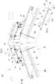
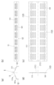
図1(a)に示す本発明の実施例1の換気構造は、左右対称状の屋根棟に設けられる開放部Oに対して配設される、それぞれ二部材ずつの棟下地3と、該棟下地3に固定される換気棟フレーム2と、該換気棟フレーム2に裏面側から支持される、図2(a),(b)に示す換気棟包み1とからなる。
前記換気棟包み1と屋根面40との間には、排水用の空間13が設けられ、前記換気棟包み1には、複数の通気孔111が設けられ、該通気孔111が上向きルーバー形状(111a)に形成されている。
なお、図1(a)中に示す長く大きな白抜き矢印は側方からの風を示し、やや小さく屈曲している白抜き矢印は突出部分111aに当たる吹き上げ風と、内部から吸い出される空気とを示し、短く太い白抜き矢印は室内側からの排出空気を示し、短く小さな白抜き矢印は室内側にて流動(拡散)する排出空気を示している。
The ventilation structure according to the first embodiment of the present invention shown in FIG. It consists of a
A
Note that the long, large white arrow shown in FIG. 1(a) indicates the wind from the side, and the slightly smaller, curved white arrow indicates the upward wind hitting the protruding
前記換気棟包み1は、前述のように屋根面に平行状に配設される二つの換気面部11,11と、該換気面部11,11の水下端を下向きに延在させて略垂直面状に配設される側面部12,12とを備えている。側面部12の下端は、屋根面40との間には隙間が形成されるように臨んでいるが、該隙間が前記排水用の空間13である。
前記換気面部11には、図2(b),(c)に示すように傾斜方向に3段、長さ方向に16列の通気孔111が上向きルーバー形状(111a)に形成され、前記側面部12には、上下方向に1段、長さ方向に16列の孔121が形成されている。
As described above, the
As shown in FIGS. 2(b) and 2(c), ventilation holes 111 are formed in the
なお、この通気孔111は、図2(c),(d)に示すように金属板材にU字状の切り込みを形成する加工の後に切り込み内部を上方へ立ち上げる加工を施すことにより、先端(突出部分)111aが傾斜状に湾曲している形状である。また、側面部12の孔121についても、その形状及び加工については前記通気孔111と同様に形成し、その突出部分121aについても同様に形成した。
その後、頂部に相当する中央部分に折曲加工が施されることで換気面部11,11が形成されると共に、各換気面部11にそれぞれ折曲加工が施されることで側面部12が形成されて換気棟包み1が成形される。なお、図2(c),(d)中における括弧表示は、成形前の部位を示している。
As shown in FIGS. 2(c) and 2(d), this
Thereafter, the
前記棟下地3は、前述のように屋根棟に設けられる開放部Oに対して配設される部材であって、図1(b)に示すように屋根面40への凹状固定部31と、該凹状固定部31の水上端が立ち上がって水上側へ延在する上方固定部32と、前記凹状固定部31の水下端が立ち上がって水下側へ延在する下方固定部33とを備えている。
なお、前記凹状固定部31の底部(固定面部31a)には、屋根下地(垂木8)に達する固着具3bを打ち込んで当該棟下地3を固定している。この実施例1では、固着具3bの頭部に不定形の止水材3cが射出されて配され、固定面部31aの裏面側には、シート状の止水材3dが配されている。
また、前記下方固定部33の水下端が下方へ折り曲げられた下向き片34が形成され、該下向き片34の下端は、屋根面40との間には隙間35が形成されるように臨んでいるが、該隙間35から内部で結露した水分や雨水が排水される。
The
Note that the
Further, the lower end of the lower fixing
前記換気棟フレーム2は、棟下地3に固定されると共に、前記換気棟包み1を裏面側から支持する部材である。
この換気棟フレーム2は、図1(b)に示すように前記棟下地3の上方固定部32及び下方固定部33に支持される覆い面部21と、該覆い面部21の水上端が立ち上がって水上側へ延在する上方支持部23と、前記覆い面部21の水下端が立ち上がる下方支持部24とを備えている。
この覆い面部21は、その水上部分が棟下地3の上方固定部32に支持され、その水下部分が棟下地3の下方固定部33に支持される平面状であって、その間の部分が前記底部(固定面部31a)の上方を覆っている。
なお、図中の符号22は、覆い面部21の水上端が垂直状に立ち上がった部位であり、上方支持部23との間に形成されている起立状部を示している。
The
As shown in FIG. 1(b), the
This covering
In addition, the code|
この実施例1では、前記棟下地3と前記換気棟フレーム2との間に棟包み5が配設されている。
この棟包み5は、図1(b)に示すように前記棟下地3の凹状固定部31を覆う面状部51と、この面状部51の水上端を略垂直状に立ち上げその上端を水下側へ折り曲げた立ち上げ片部52と、面状部51の水下端を略垂直状に折り下げその下端を水下側へ折り曲げたL字状の折り下げ片部53とからなる。この折り下げ片部53の下端は、屋根面40との間には隙間54が形成されるように臨んでおり、該隙間54から内部で結露した水分や雨水が排水される。
この棟包み5は、前記棟下地3の取り付け後に、水下側から係合状に臨ませ、その面状部51を棟下地3の上方固定部32及び下方固定部33に沿わせると共にその折り下げ片部53を棟下地3の下向き片34に沿わせ、側方固定具5bにて固定する。
In this first embodiment, a
As shown in FIG. 1(b), the
After the
屋根面40は、横葺き外装材である屋根材4にて形成され、その裏面側には断熱バックアップ材7が配設され、更にその裏面側には防水シート材である防水層6bが張設され、その裏面側にはボード状の野地板6Aが配され、最室内側には垂木8が所定間隔にて配設されている。
そのため、室内側で暖められた内部空気は、図中に白抜き矢印にて示すように上方へ上昇し、二つの傾斜面における棟下地3,3間及び換気棟フレーム2,2間を上昇し、換気棟包み1の裏面側に達している。
なお、図1(a)中の符号1bは側方固定具であり、1cは気密材(モヘヤ)であり、1dは裏打ち材である。
The
Therefore, the internal air warmed on the indoor side rises upward as indicated by the white arrow in the figure, and rises between the
In addition, the code|
これらの各部材にて形成される実施例1の換気構造では、屋根棟に設けられる開放部Oに対して配設する、棟下地3と、該棟下地3に固定される換気棟フレーム2と、該換気棟フレーム2に裏面側から支持される換気棟包み1と、からなり、換気棟包み1と屋根面40との間には、排水用の空間13が設けられ、換気棟包み1には、複数の通気孔111が設けられ、該通気孔111が上向きルーバー形状(111a)に形成されている。
図1(a)中には、白抜き矢印にて空気の流れが示されている。
これより明らかなように、室内側の空気が、複数の通気孔111から吸い出される構造であるから、建築高さを過剰に増大させることなく、一般住宅等の屋根棟に設けられて室内の換気を確実に行うことができる。即ち換気棟包み1には、屋根面に平行状の換気面部11が形成され、該換気面部11に複数の通気孔111が形成されるため、それぞれの上向きルーバー(111a)に側方(この図では右方)から吹き上げ風が当たることにより、内部空気の吸い出し作用が果たされる。
In the ventilation structure of Example 1 formed of these respective members, a
In FIG. 1(a), air flow is indicated by white arrows.
As is clear from this, since the structure is such that indoor air is sucked out through the plurality of
このように複数の通気孔111の上向きルーバー(突出部分111a)に建物を伝う吹き上げ風が当たることにより、各通気孔111の上方に減圧空間が形成され、室内の空気の吸い出し作用が果たされ、室内側の空気が室外側へ排気される。しかも、このような複数の通気孔111を、屋根面40に平行状に配設される換気棟包み11に形成していることで、一般住宅等の屋根棟でも建築高さを過剰に増大させることなく、室内の換気を確実に行うことができる。
また、換気構造の中でも、室内で暖められた空気は、より高い頂部付近に対流しようとするが、この換気構造では、頂部付近に通気孔111が設けられるので、排気作用が高いものとなる。
In this way, when the upward louvers (projecting
Also, in the ventilation structure, air warmed indoors tends to convect near the top, which is higher, but in this ventilation structure, the
なお、この実施例1の換気構造では、屋根面40との間に排水用の空間13が形成されると共に、隙間35,54も形成されているので、内部に浸入した雨水や内部で結露した水分を外部へ排出することができる。
また、これらの排水用の空間13、隙間35,54は吹き込み風に正対しているので、外部空気の導入作用が果たされる。
In addition, in the ventilation structure of Example 1, the
Further, since these
図3に示す本発明の実施例2の換気構造は、片流れ状の屋根棟に設けられる開放部O'に対して配設される棟下地3と、該棟下地3に固定される換気棟フレーム2と、該換気棟フレーム2に裏面側から支持される換気棟包み1'とからなる。
そして、前記実施例1と同様に前記換気棟包み1'と屋根面40との間には、排水用の空間13が設けられ、前記換気棟包み1'には、複数の通気孔111が設けられ、該通気孔111が上向きルーバー形状(111a)に形成されている。
この実施例2では、換気棟フレーム2や棟下地3についても、棟包み5や屋根面40を形成する部材についても、前記実施例1と全く同様であるから図中に同一符号を付して説明を省略する。
The ventilation structure according to the second embodiment of the present invention shown in FIG. 2, and a ventilation ridge wrapper 1' supported by the
As in the first embodiment, a
In this second embodiment, the
この実施例2における換気棟包み1'は、一つの換気面部11と、該換気面部11の水下端を下向きに延在させて略垂直面状に配設される側面部12と、を備える点では前記実施例1と同様であるが、この実施例2の前記換気面部11の頂部から鉛直状に下方側へ延在する縦状面部14が延設されている。この縦状面部14の下端には、裏面側へ折り返した係止部141が設けられている。
なお、裏打ち材1d'は、換気面部11の頂部付近だけではなく、縦状面部14の裏面側にも亘っている。
The ventilation ridge wrapper 1' in this second embodiment includes one
Note that the
これらの各部材にて形成される実施例2の換気構造でも、前記実施例1と同様の効果を奏することができる。
即ちこの換気構造でも、室内側の空気が、複数の通気孔111から吸い出される構造であるから、建築高さを過剰に増大させることなく、一般住宅等の屋根棟に設けられて室内の換気を確実に行うことができる。即ち換気棟包み1'には、屋根面に平行状の換気面部11が形成され、該換気面部11に複数の通気孔111が形成されているため、それぞれの上向きルーバー(111a)に側方(この図では右方)から吹き上げ風が当たることにより、内部空気の吸い出し作用が果たされる。
The ventilation structure of the second embodiment formed of these members can also provide the same effects as the first embodiment.
In other words, in this ventilation structure, the air inside the room is sucked out through the plurality of
また、この実施例2の換気構造でも、屋根面40との間に排水用の空間13が形成されると共に、隙間35,54も形成されているので、内部に浸入した雨水や内部で結露した水分を外部へ排出することができる。これらの排水用の空間13、隙間35,54は吹き込み風に正対しているので、外部空気の導入作用が果たされる。
In addition, in the ventilation structure of Example 2, the
図4に示す本発明の実施例3の換気構造は、前記実施例2と同様に片流れ状の屋根棟に設けられる開放部O"に対して配設される棟下地3"と、該棟下地3"に固定される換気棟フレーム2と、該換気棟フレーム2に裏面側から支持される、図5(a),(b)に示す換気棟包み1"とからなる。
そして、前記実施例1と同様に前記換気棟包み1"と屋根面40"との間には、排水用の空間13が設けられ、前記換気棟包み1"には、複数の通気孔111が設けられ、該通気孔111が上向きルーバー形状(111a)に形成されている。
この実施例3では、換気棟フレーム2については、前記実施例1,2と全く同様であるから図中に同一符号を付して説明を省略する。なお、棟下地3"及び屋根面40"や棟包み5"については後述する。
The ventilation structure according to the third embodiment of the present invention shown in FIG. It consists of a
As in the first embodiment, a
In this third embodiment, the
この実施例3における換気棟包み1"は、一つの換気面部11"と、該換気面部11"の水下端を下向きに延在させて略垂直面状に配設される側面部12と、前記換気面部11"の頂部から鉛直状に下方側へ延在する縦状面部14が延設されている点では前記実施例2と同様であるが、より傾斜勾配が緩い屋根面40"に応じて換気面部11"の傾斜勾配もより水平状に近く配設されている。
なお、側面部12の下端は、屋根面40"との間には隙間が形成されるように臨んでいるが、該隙間が前記排水用の空間13である点などは前記実施例2と同様である。また、裏打ち材1d"は、換気面部11"の頂部付近の裏面側のみに配設されている。
The ventilation ridge wrapper 1'' in this third embodiment includes one ventilation surface portion 11'', a
Note that the lower end of the
前記換気面部11"には、図5(b),(c)に示すように傾斜方向に3段、長さ方向に16列の通気孔111が上向きルーバー形状(111a)に形成され、前記側面部12には、上下方向には1段、長さ方向に16列の孔121が形成されている。
なお、この通気孔111は、前記実施例1と全く同様に成形できる。また、図5(c),(d)中における括弧表示は、成形前の部位を示している。
As shown in FIGS. 5(b) and 5(c), ventilation holes 111 are formed in the ventilation surface portion 11'' in an upward louver shape (111a) in 3 stages in the inclination direction and 16 rows in the length direction, and In the
Note that this
また、この実施例3における棟下地3"は、一定厚みで断面矩形状の木質材にて形成されている。そのため、この棟下地3"に打ち込まれる固着具3b"も側方固定具5b"も、木質用の固着ビスが用いられている。
また、この実施例3における屋根面40"は、一定厚みの屋根材4"にて形成され、その裏面側には防水シート材である防水層6b、及びボード状の野地板6Aが配され、最室内側には垂木8が所定間隔にて配設されている。
また、この実施例3における棟包み5"は、水上端の立ち上げ片部52"が鉛直状である以外は前記実施例1,2における棟包みと同様であるから図面に同一符号を付して説明を省略する。
Further, the
Further, the roof surface 40'' in this
Also, the
これらの各部材にて形成される実施例3の換気構造でも、前記実施例1,2と同様の効果を奏することができる。
即ちこの換気構造でも、室内側の空気が、複数の通気孔111から吸い出される構造であるから、建築高さを過剰に増大させることなく、一般住宅等の屋根棟に設けられて室内の換気を確実に行うことができる。即ち換気棟包み1"には、屋根面に平行状の換気面部11"が形成され、該換気面部11"に複数の通気孔111が形成されているため、それぞれの上向きルーバー(111a)に側方(この図では右方)から吹き上げ風が当たることにより、内部空気の吸い出し作用が果たされる。
The ventilation structure of the third embodiment formed of these members can also provide the same effects as the first and second embodiments.
In other words, in this ventilation structure, the air inside the room is sucked out through the plurality of
また、この実施例3の換気構造でも、屋根面40"との間に排水用の空間13が形成されると共に、隙間35,54も形成されているので、内部に浸入した雨水や内部で結露した水分を外部へ排出することができる。これらの排水用の空間13、隙間35,54は吹き込み風に正対しているので、外部空気の導入作用が果たされる。
Also, in the ventilation structure of this third embodiment, the
1,1',1" 換気棟包み
11,11" 化粧面(換気面部)
111 通気孔
111a 突出部分
12 側面部
121 孔
121a 突出部分
13 排水用の空間
1b 側方固定具
1c 気密材
1d 裏打ち材
2 換気棟フレーム
21 覆い面部
22 起立状部
23 上方支持部
24 下方支持部
2b 固定具
2c 弾性止水材
3 棟下地
31 凹状固定部
32 上方固定部
33 下方固定部
34 下向き片
35 隙間
3b,3b" 固着具
3c 止水材
3d 止水材
4 屋根材
40,40" 屋根面
5,5" 棟包み
51 面状部
52,52" 立ち上げ片部
53 折り下げ片部
54 隙間
5b,5b" 側方固定具
6A 野地板
6b 防水層
7 断熱バックアップ材
8 垂木
O,0',0" 開放部
1,1',1"
111
Claims (3)
前記換気棟包みと屋根面との間には、排水用の空間が設けられ、
前記換気棟包みには、複数の通気孔が設けられ、該通気孔が上向きルーバー形状に形成されていることを特徴とする換気構造。 A ventilation structure arranged for an open part provided in a roof ridge, and consisting of a ridge base, a ventilation ridge frame fixed to the ridge base, and a ventilation ridge wrapper supported by the ventilation ridge frame from the back side. And,
A drainage space is provided between the ventilation ridge wrapper and the roof surface,
A ventilation structure characterized in that the ventilation ridge wrapper is provided with a plurality of ventilation holes, and the ventilation holes are formed in an upward louver shape.
Priority Applications (1)
| Application Number | Priority Date | Filing Date | Title |
|---|---|---|---|
| JP2022078572A JP2023167405A (en) | 2022-05-12 | 2022-05-12 | ventilation structure |
Applications Claiming Priority (1)
| Application Number | Priority Date | Filing Date | Title |
|---|---|---|---|
| JP2022078572A JP2023167405A (en) | 2022-05-12 | 2022-05-12 | ventilation structure |
Publications (1)
| Publication Number | Publication Date |
|---|---|
| JP2023167405A true JP2023167405A (en) | 2023-11-24 |
Family
ID=88838017
Family Applications (1)
| Application Number | Title | Priority Date | Filing Date |
|---|---|---|---|
| JP2022078572A Pending JP2023167405A (en) | 2022-05-12 | 2022-05-12 | ventilation structure |
Country Status (1)
| Country | Link |
|---|---|
| JP (1) | JP2023167405A (en) |
Citations (7)
| Publication number | Priority date | Publication date | Assignee | Title |
|---|---|---|---|---|
| JPS59171144U (en) * | 1983-04-30 | 1984-11-15 | 松下電工株式会社 | Structure of ventilation building |
| US4545291A (en) * | 1984-03-08 | 1985-10-08 | Klauer Manufacturing Company | Roofline ventilators |
| JP2001329668A (en) * | 2000-05-23 | 2001-11-30 | Asahi Kinzoku Kk | Ventilation building |
| JP2011252361A (en) * | 2010-06-04 | 2011-12-15 | Hauzesanei Co Ltd | Ventilation ridge |
| JP2017040105A (en) * | 2015-08-20 | 2017-02-23 | 株式会社ハウゼコ | Flashing structure and ventilation building structure using the same |
| JP2018150711A (en) * | 2017-03-13 | 2018-09-27 | 元旦ビューティ工業株式会社 | Ventilation structure |
| JP2022063957A (en) * | 2020-10-13 | 2022-04-25 | 積水ハウス株式会社 | Construction method of snow-proof ventilation ridge structure and snow-proof ventilation ridge structure |
-
2022
- 2022-05-12 JP JP2022078572A patent/JP2023167405A/en active Pending
Patent Citations (7)
| Publication number | Priority date | Publication date | Assignee | Title |
|---|---|---|---|---|
| JPS59171144U (en) * | 1983-04-30 | 1984-11-15 | 松下電工株式会社 | Structure of ventilation building |
| US4545291A (en) * | 1984-03-08 | 1985-10-08 | Klauer Manufacturing Company | Roofline ventilators |
| JP2001329668A (en) * | 2000-05-23 | 2001-11-30 | Asahi Kinzoku Kk | Ventilation building |
| JP2011252361A (en) * | 2010-06-04 | 2011-12-15 | Hauzesanei Co Ltd | Ventilation ridge |
| JP2017040105A (en) * | 2015-08-20 | 2017-02-23 | 株式会社ハウゼコ | Flashing structure and ventilation building structure using the same |
| JP2018150711A (en) * | 2017-03-13 | 2018-09-27 | 元旦ビューティ工業株式会社 | Ventilation structure |
| JP2022063957A (en) * | 2020-10-13 | 2022-04-25 | 積水ハウス株式会社 | Construction method of snow-proof ventilation ridge structure and snow-proof ventilation ridge structure |
Similar Documents
| Publication | Publication Date | Title |
|---|---|---|
| US20050193671A1 (en) | Soffit structure | |
| JP4000145B2 (en) | Roof structure using external insulation method | |
| JP2005048422A (en) | Ventilating ridge structure | |
| JP3729337B2 (en) | Natural ventilation method of building and natural ventilation structure therefor | |
| JP3583111B2 (en) | Ventilation building structure | |
| JP2002121833A (en) | Passive ventilation house | |
| CA2458006A1 (en) | Soffit structure | |
| JP3618561B2 (en) | Tile building structure and attic ventilation system | |
| JPS6262144A (en) | Ventilating device | |
| JP3649922B2 (en) | Ventilation drain for tile building and ventilation member for tile building | |
| JPH11256750A (en) | Attic ventilation structure | |
| JP3983462B2 (en) | Building ventilation structure | |
| JP4052760B2 (en) | Underfloor ventilation structure of outdoor floor | |
| JP3065676B2 (en) | Exterior wall structure of wooden house with ventilation layer | |
| JP2017061810A (en) | Wall structure | |
| JP2000145071A (en) | Building wrapping structure and attic ventilation system | |
| JPH0624510Y2 (en) | Ventilation | |
| JPS6317764Y2 (en) | ||
| JP2002266443A (en) | House ventilation structure | |
| JP2000027326A (en) | Building ventilation structure and unit building ventilation structure | |
| JP2025178897A (en) | Ventilated layer connection device, wooden building, and method for manufacturing wooden building | |
| JP2003268892A (en) | Exhaust tower | |
| JP2005226279A (en) | Wall structure | |
| JPS6339284Y2 (en) | ||
| JPH0311640Y2 (en) |
Legal Events
| Date | Code | Title | Description |
|---|---|---|---|
| A621 | Written request for application examination |
Free format text: JAPANESE INTERMEDIATE CODE: A621 Effective date: 20250205 |
|
| A977 | Report on retrieval |
Free format text: JAPANESE INTERMEDIATE CODE: A971007 Effective date: 20251118 |
|
| A131 | Notification of reasons for refusal |
Free format text: JAPANESE INTERMEDIATE CODE: A131 Effective date: 20251223 |
|
| A521 | Request for written amendment filed |
Free format text: JAPANESE INTERMEDIATE CODE: A523 Effective date: 20260219 |
|
| A131 | Notification of reasons for refusal |
Free format text: JAPANESE INTERMEDIATE CODE: A131 Effective date: 20260507 |
|
| A521 | Request for written amendment filed |
Free format text: JAPANESE INTERMEDIATE CODE: A523 Effective date: 20260626 |