JP2023061321A - Automatic door frame, building, automatic door frame unit, construction method of automatic door frame unit, and construction method of building - Google Patents
Automatic door frame, building, automatic door frame unit, construction method of automatic door frame unit, and construction method of building Download PDFInfo
- Publication number
- JP2023061321A JP2023061321A JP2021171251A JP2021171251A JP2023061321A JP 2023061321 A JP2023061321 A JP 2023061321A JP 2021171251 A JP2021171251 A JP 2021171251A JP 2021171251 A JP2021171251 A JP 2021171251A JP 2023061321 A JP2023061321 A JP 2023061321A
- Authority
- JP
- Japan
- Prior art keywords
- automatic door
- frame
- door frame
- plate portion
- building
- Prior art date
- Legal status (The legal status is an assumption and is not a legal conclusion. Google has not performed a legal analysis and makes no representation as to the accuracy of the status listed.)
- Granted
Links
Images



Landscapes
- Door And Window Frames Mounted To Openings (AREA)
- Power-Operated Mechanisms For Wings (AREA)
- Residential Or Office Buildings (AREA)
- Specific Sealing Or Ventilating Devices For Doors And Windows (AREA)
Abstract
Description
本発明は、自動ドア枠、建物、自動ドア枠ユニット、自動ドア枠ユニットの施工方法、及び、建物の施工方法、に関する。 The present invention relates to an automatic door frame, a building, an automatic door frame unit, an automatic door frame unit construction method, and a building construction method.
自動ドアでは、駆動部の配置スペースに雨水等が容易に浸入しないように雨掛かり対策が施されている。特許文献1には、この種の自動ドアが開示されている。
In the automatic door, measures against rainwater are taken so that rainwater and the like do not easily enter the installation space of the drive unit.
しかしながら、既存の自動ドアで行われる雨掛かり対策は、自動ドアの周囲の部位の施工状況に合わせて実行され、自動ドア枠を建物の躯体に取り付ける施工タイミングと一致しない。そのため、通常、自動ドア枠の配置スペースに駆動部を配置する施工タイミングは、自動ドア枠を建物の躯体に取り付けた後で、かつ、雨掛かり対策が施された後の、所定のタイミングとなる。このような施工タイミングの違いは、例えば、乗り入れ業者のタイミング調整、施工現場での作業場所の確保など、の観点で、重複した手間が発生する可能性がある。そのため、施工効率を低下させるおそれがある。 However, the existing automatic door measures against raindrops are executed in accordance with the construction status of the surrounding parts of the automatic door, and do not match the construction timing of attaching the automatic door frame to the building frame. Therefore, the construction timing for arranging the drive unit in the arrangement space of the automatic door frame is usually a predetermined timing after the automatic door frame is attached to the building frame and after measures against rain are taken. . Such a difference in construction timing may cause duplication of labor in terms of, for example, adjusting the timing of the contractor and securing a work place at the construction site. Therefore, there is a possibility that construction efficiency may be reduced.
本発明は、建物の周囲の部位とは無関係に、駆動部が配置される配置スペースの雨掛かり対策を実行可能な、自動ドア枠、建物、自動ドア枠ユニット、自動ドア枠ユニットの施工方法、及び、建物の施工方法、を提供することを目的とする。 The present invention provides an automatic door frame, a building, an automatic door frame unit, and an automatic door frame unit construction method that can implement measures against rain in an arrangement space where a driving unit is arranged, regardless of the surrounding parts of the building. And, it aims at providing the construction method of a building.
本発明の第1の態様としての自動ドア枠は、上枠の内部に、ドア部を動かす駆動部を配置可能な配置スペースが区画されており、前記配置スペースの上方を覆う位置に設けられている止水構造を備える。 In the automatic door frame according to the first aspect of the present invention, an arrangement space is defined in the interior of the upper frame in which a drive unit for moving the door can be arranged, and the upper frame is provided at a position covering the upper part of the arrangement space. Equipped with a water stop structure.
本発明の1つの実施形態として、前記上枠は、前記配置スペースの上方を覆うカバー部を備え、前記止水構造は、鉛直方向に貫通する貫通孔が形成されていない前記カバー部を含む。 As one embodiment of the present invention, the upper frame includes a cover portion that covers an upper portion of the arrangement space, and the water stop structure includes the cover portion that does not have a through hole penetrating therethrough in a vertical direction.
本発明の1つの実施形態として、前記上枠は、前記配置スペースの上方を覆うカバー部を備え、前記カバー部には、鉛直方向に貫通する貫通孔が形成されており、前記止水構造は、前記カバー部と、前記カバー部に形成されている前記貫通孔を閉塞する閉塞部材と、を含む。 As one embodiment of the present invention, the upper frame includes a cover portion that covers an upper portion of the arrangement space, the cover portion is formed with a through-hole penetrating in a vertical direction, and the water stop structure is , the cover portion, and a closing member that closes the through hole formed in the cover portion.
本発明の第2の態様としての建物は、上記自動ドア枠を備える。 A building as a second aspect of the present invention includes the above automatic door frame.
本発明の第3の態様としての自動ドア枠ユニットは、ドア部を動かす駆動部と、上枠の内部に、前記駆動部が配置されている配置スペースを区画している自動ドア枠と、を備え、前記自動ドア枠は、前記駆動部の上方を覆う位置に設けられている止水構造を備える。 An automatic door frame unit as a third aspect of the present invention includes a drive section for moving a door section, and an automatic door frame defining an arrangement space in which the drive section is arranged inside an upper frame. Further, the automatic door frame has a water stop structure provided at a position covering an upper side of the drive unit.
本発明の第4の態様としての自動ドア枠ユニットは、ドア部を動かす駆動部と、上枠の内部に、前記駆動部が配置されている配置スペースを区画している自動ドア枠と、を備え、前記自動ドア枠は、前記駆動部の上方を覆う位置に止水部材が配置された状態で前記止水部材を取り付け可能な取付部を備える。 An automatic door frame unit as a fourth aspect of the present invention includes a drive section for moving a door section, and an automatic door frame defining an arrangement space in which the drive section is arranged inside an upper frame. The automatic door frame includes an attachment portion to which the water cutoff member can be attached in a state where the water cutoff member is arranged at a position covering an upper portion of the driving portion.
本発明の第5の態様としての、自動ドア枠ユニットの施工方法では、前記自動ドア枠ユニットは、ドア部を動かす駆動部と、上枠の内部に、前記駆動部が配置されている配置スペースを区画している自動ドア枠と、を備え、前記自動ドア枠は、前記駆動部の上方を覆う位置に設けられている止水構造を備え、前記自動ドア枠ユニットを建物の躯体に取り付ける取付工程を含む。 In the automatic door frame unit construction method as a fifth aspect of the present invention, the automatic door frame unit includes a drive section for moving a door section, and an arrangement space in which the drive section is arranged inside an upper frame. and an automatic door frame that partitions the automatic door frame, the automatic door frame having a waterproof structure provided at a position covering the upper part of the driving part, and mounting the automatic door frame unit to a building skeleton Including process.
本発明の第6の態様としての、自動ドア枠ユニットの施工方法では、前記自動ドア枠ユニットは、ドア部を動かす駆動部と、上枠の内部に、前記駆動部が配置されている配置スペースを区画している自動ドア枠と、を備え、前記自動ドア枠ユニットを建物の躯体に取り付ける取付工程と、前記取付工程と同時又は後に、前記駆動部の上方を覆う位置に止水構造を形成する、止水工程と、を含む。 In the automatic door frame unit construction method as a sixth aspect of the present invention, the automatic door frame unit includes a drive section for moving a door section, and an arrangement space in which the drive section is arranged inside an upper frame. a mounting step of mounting the automatic door frame unit to a building frame; and a water stopping step.
本発明の第7の態様としての、建物の施工方法は、自動ドアを備える建物の施工方法であって、躯体工事と同時、又は、躯体工事後で防水工事完了前に、自動ドア枠ユニットの上記施工方法を含む。 A seventh aspect of the present invention is a construction method for a building, which is a construction method for a building having an automatic door, wherein the automatic door frame unit is installed at the same time as the construction of the building frame or before the completion of the waterproofing work after the construction of the building frame. Including the above construction method.
本発明によれば、建物の周囲の部位とは無関係に、駆動部が配置される配置スペースの雨掛かり対策を実行可能な、自動ドア枠、建物、自動ドア枠ユニット、自動ドア枠ユニットの施工方法、及び、建物の施工方法、を提供することができる。 According to the present invention, construction of an automatic door frame, a building, an automatic door frame unit, and an automatic door frame unit capable of implementing rain protection measures for the installation space in which the drive unit is arranged, regardless of the surrounding parts of the building. A method and a construction method for a building can be provided.
以下、本発明に係る、自動ドア枠、建物、自動ドア枠ユニット、自動ドア枠ユニットの施工方法、及び、建物の施工方法、の実施形態について図面を参照して例示説明する。各図において共通する構成には同一の符号を付している。 Embodiments of an automatic door frame, a building, an automatic door frame unit, an automatic door frame unit construction method, and a building construction method according to the present invention will be described below by way of example with reference to the drawings. The same reference numerals are given to the configurations that are common in each figure.
図1は、建物200の区画壁201の開口部201aに取り付けられている自動ドア100の正面図である。
FIG. 1 is a front view of an
まず、自動ドア100が適用される建物200の一例の概要について説明する。本実施形態の建物200は、例えば鉄骨造の軸組みを有する3階建ての集合住宅である。但し、建物200の階層数は特に限定されない。また、建物200は、例えば、戸建て住宅であってもよい。
First, an outline of an example of a
本実施形態の建物200は、鉄筋コンクリート造の基礎と、柱や梁などの軸組部材で構成された軸組架構を有し、基礎に支持される上部構造体と、を備えてよい。本実施形態の上部構造体は、鉄骨造の軸組架構を有するが、例えば、木造の軸組みを有してもよく、その構造は特に限定されない。また、本実施形態の建物200の軸組架構を構成する軸組部材は、予め規格化(標準化)されたものであり、予め工場にて製造されたのち建築現場に搬入されて組み立てられる。
The
より具体的に、本実施形態の建物200の上部構造体は、上述の軸組架構と、外壁と、床202と、屋根と、を備える。
More specifically, the upper structure of the
外壁は、建物200の屋内空間と屋外空間とを区画する壁である。本実施形態の建物200の外壁は、例えば、軽量気泡コンクリート(ALC)からなるパネル状の外装材が連接されて構成された外部仕上げ層を備える。但し、外装材は、金属系や窯業系のサイディング、押出成形セメント板、木質系パネルなどであってもよい。
The outer wall is a wall that separates the indoor space and the outdoor space of the
また、外壁は、フェノールフォーム等の発泡樹脂系のパネル状の断熱材が外装仕上げ層の内面に沿って連接されて構成された断熱層を備える。但し、断熱材は、ロックウール等の繊維系の構成であってもよい。 In addition, the outer wall is provided with a heat insulating layer formed by connecting a panel-shaped heat insulating material made of foamed resin such as phenol foam along the inner surface of the exterior finishing layer. However, the heat insulating material may be made of fibers such as rock wool.
更に、外壁は、石膏ボートと石膏ボード表面に貼設された壁クロス等の仕上げ材とで構成された内装材からなる内部仕上げ層を備える。但し、内装材の構成は本実施形態の構成に限られない。 Furthermore, the outer wall is provided with an internal finishing layer made of an interior material composed of a gypsum board and a finishing material such as a wall cloth attached to the surface of the gypsum board. However, the configuration of the interior material is not limited to the configuration of this embodiment.
本実施形態の建物200の床202は、床スラブ材を含む。床スラブ材は、軸組架構の梁間に架設され、梁により直接的又は間接的に支持される。床スラブ材としては、例えば、ALCパネルを用いることできるが、折板、押出成形セメント板、木質系パネルなどの別の部材を用いてもよい。床202は、床スラブ材に加えて、例えば、床スラブ材に対して直接的又は間接的に取り付けられる、下階の天井面202aを構成する天井内装材を含んでよい。また、床202は、床スラブ材上に積層された、上階の床面202bを構成するフローリング等の床内装材などを含む構成であってもよい。
The
本実施形態の建物200の屋根は、陸屋根である。陸屋根を構成する屋根床スラブ材についても、上述した床スラブ材と同様、ALCパネルを用いることができるが、ALCパネルに限られるものではない。また、屋根床スラブ材は、例えば塩化ビニル樹脂から形成されている防水シート等により覆われることにより、防水処理が施されている。また、建物200の屋根は、陸屋根に限られず、スレート等の屋根外装材を用いた勾配屋根であってもよい。
The roof of the
次に、建物200の区画壁201の開口部201aに取り付けられる自動ドア100について説明する。区画壁201は、例えば、上述の外壁であってもよく、屋内空間同士を仕切る間仕切壁であってもよい。本実施形態では、一例として、区画壁201としての外壁の開口部201aに取り付けられる自動ドア100について説明する。
Next, the
図1に示すように、自動ドア100は、本発明に係る自動ドア枠の一実施形態としての自動ドア枠1を備える。より具体的に、本実施形態の自動ドア100は、自動ドア枠1と、駆動部2と、ドア部3と、固定板部4と、を備える。
As shown in FIG. 1, the
自動ドア枠1は、上枠11と、下枠12と、2本の縦枠13、14と、を備える。図1は、自動ドア100を屋外側から見た正面図である。以下、説明の便宜上、図1に示す正面視で左側にある縦枠13を「左縦枠13」と記載し、右側にある縦枠14を「右縦枠14」と記載する。
The
図1に示すように、自動ドア枠1は、上枠11、下枠12、左縦枠13及び右縦枠14により構成される矩形状の枠である。より具体的に、上枠11は、開口部201aの上側の開口端に沿って水平方向に延在している。下枠12は、開口部201aの下側の開口端に沿って水平方向に延在している。左縦枠13は、開口部201aの水平方向の一方側の開口端に沿って鉛直方向に延在している。左縦枠13は、上枠11の一端部と、下枠12の一端部と、を連結している。右縦枠14は、開口部201aの水平方向の他方側の開口端に沿って鉛直方向に延在している。右縦枠14は、上枠11の他端部と、下枠12の他端部と、を連結している。
As shown in FIG. 1, the
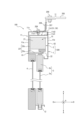
図2は、自動ドア100の縦断面図である。図2に示すように、本実施形態の上枠11は、内部に、ドア部3を動かす駆動部2を配置可能な配置スペース15を区画している。ここで、上枠11、下枠12、左縦枠13及び右縦枠14それぞれの枠の内部とは、各枠の正面と背面との間に位置する内部空間を意味する。各枠の正面とは、自動ドア枠1の枠面の面内方向A(区画壁201の面内方向と同じ方向)と直交する、自動ドア枠1の枠厚み方向B(区画壁201の厚み方向と同じ方向)の一方側の面である。また、各枠の背面とは、自動ドア枠1の枠面の面内方向Aと直交する枠厚み方向Bの他方側の面である。
FIG. 2 is a longitudinal sectional view of the
より具体的に、本実施形態の上枠11は、枠厚み方向Bの一方側に位置し、上枠11の正面を構成する正面板部11aと、枠厚み方向Bの他方側に位置し、上枠11の背面を構成する背面板部11bと、正面板部11aの上端部と背面板部11bの上端部との間に配置され、上枠11の上面を構成する上面板部11cと、この上面板部11cの下方で、正面板部11aと背面板部11bとの間に配置されているカバー部51としてのカバー板部11dと、を備える。図2に示すように、本実施形態の上枠11では、正面板部11a、背面板部11b及びカバー板部11dが、これら内部に、配置スペース15を区画している。換言すれば、図2に示すように、正面板部11a及び背面板部11bは、鉛直方向において、配置スペース15に配置されている駆動部2の上端より上方の位置から、配置スペース15に配置されている駆動部2の下端よりも下方の位置まで、延在している。また、本実施形態の正面板部11aの下端部には、固定板部4が固定されている。上面板部11cには、ボルトなどの締結部材208を挿通可能な挿通孔11c1が形成されている。上面板部11cの下面には、例えば、挿通孔11c1に上方から下方に向かって挿通されるボルトが螺合可能なナットが、予め固定されていてよい。
More specifically, the
本実施形態の上枠11では、正面板部11a、上面板部11c及びカバー板部11dが、折り曲げ加工若しくは溶接等の接合により、又は、押し出し成型等の一体成型により、一体の第1枠材61を構成している。また、本実施形態の上枠11では、背面板部11bを構成する第2枠材62が、上述の第1枠材61に対して、取り外し可能に取り付けられている。このようにすることで、第2枠材62を、第1枠材61に対して取り外すことで、配置スペース15に配置される駆動部2のメンテナンス等を容易に実行することができる。但し、第2枠材62は、第1枠材61に対して、例えば回動可能な構成など、移動可能に取り付けられていてもよい。第2枠材62が第1枠材61に対して取り付けられている状態での、第1枠材61と第2枠材62との間の微小な間隙には、例えば弾性体からなるシール部材を挟み込む等してもよい。
In the
なお、図2に示すように、カバー板部11dは、面内方向が略水平方向となる平板状のカバー板本体部11d1と、このカバー板本体部11d1の背面板部11b側の外縁から背面板部11bに沿って立ち上がる平板状の立ち上がり板部11d2と、を備える。詳細は後述するが、このような構成とすることで、上面板部11cの挿通孔11c1から浸入し、カバー板本体部11d1の上面で受けた水滴が、カバー板本体部11d1の枠厚み方向Bの外縁を伝って配置スペース15に入り込むことを防ぐことができる。
As shown in FIG. 2, the
本実施形態の上枠11は、上述したように、第1枠材61及び第2枠材62により構成されているが、この構成に限られない。上枠11の正面板部11a、背面板部11b、上面板部11c及びカバー板部11dは、全てが一体の枠材から構成されていてもよく、それぞれ別々の枠材から構成されていてもよい。また、上枠11の正面板部11a、背面板部11b、上面板部11c及びカバー板部11dのうち任意の2つ又は3つが、一体の枠材を構成していてもよい(図3参照)。なお、上枠は無目であってもよい。
As described above, the
詳細は後述するが、本実施形態の上枠11は、配置スペース15の上方を覆う位置に設けられている止水構造50を備える(図2参照)。
Although the details will be described later, the
図2に示すように、本実施形態の上枠11は、金物206、207を介して、建物200の躯体としての梁205に固定されている。具体的に、本実施形態の上枠11の上面板部11cは、長手方向と直交する断面外形がL形の2つの金物206、207を介して、ボルト等の締結部材208を用いて、梁205に固定されている。本実施形態の上枠11は、金物206、207を介して間接的に建物200の躯体に固定されているが、この構成に限られない。上枠11は、ボルト、ビス等の締結部材208により、建物200の躯体に直接的に固定されていてもよい。また、上枠11は、梁205以外の建物200の躯体に固定されていてもよい。
As shown in FIG. 2 , the
なお、図示を省略するが、本実施形態の下枠12、左縦枠13及び右縦枠14についても、間柱、梁などの建物200の躯体に、直接的又は間接的に固定されていてよい。このように、上枠11、下枠12、左縦枠13及び右縦枠14それぞれが、直接的又は間接的に、建物200の躯体に固定されることで、自動ドア枠1は、区画壁201の開口部201a内に取り付けられる。
Although illustration is omitted, the
自動ドア枠1は、例えば、ステンレス製とすることができるが、その構成材料は特に限定されない。
The
図2に示すように、駆動部2は、自動ドア枠1の上枠11が内部に区画する配置スペース15に配置されている。駆動部2は、ドア部3を動かすことができる。
As shown in FIG. 2 , the
具体的に、本実施形態の駆動部2は、駆動本体部21と、ドア支持部22と、レール部23と、を備える。
Specifically, the
駆動本体部21は、ドア支持部22を上枠11の長手方向に沿って移動可能に支持している。また、駆動本体部21は、電動モータなどの駆動源を備える。駆動本体部21は、駆動源の駆動により、ドア支持部22を上枠11の長手方向に沿って移動させることができる。
The drive
ドア支持部22は、ドア部3の上端部支持している。ドア支持部22は、レール部23に沿って、上枠11の長手方向に移動する。ドア支持部22が上枠11の長手方向に沿って移動することで、ドア部3を開閉移動させることができる。
The
レール部23は、上枠11の長手方向に沿って延在している。レール部23は、ドア支持部22を移動可能に支持している。ドア支持部22は、レール部23にガイドされて、上枠11の長手方向に移動する。より具体的に、本実施形態のレール部23は、ドア支持部22を支持し、上枠11の長手方向の移動をガイドするガイドレール23aと、このガイドレール23aから延設されており、上枠11の正面板部11aに固定されている枠固定部23bと、を備える。なお、レール部23は、上枠11と一体で形成されていてもよい。
The
ドア部3は、自動ドア100の建具である。ドア部3は、自動ドア枠1内で、水平方向に移動可能に、上枠11及び下枠12に取り付けられている。ドア部3は、鉛直方向上側から、駆動部2のドア支持部22に支持されている。ドア部3は、例えば、ガラス製の板材3aと、この板材3aの外縁部に固定されているステンレス製の框部3bと、を備える。但し、ドア部3は、駆動部2により自動ドア枠1内で移動可能に支持されていればよく、その構成は特に限定されない。
The
固定板部4は、自動ドア枠1内に固定されている袖フィックス板部である。具体的に、本実施形態の固定板部4は、上枠11、下枠12及び左縦枠13に固定されている。そのため、固定板部4自体は、自動ドア枠1内で、水平方向に移動しない。固定板部4の構成は特に限定されない。本実施形態の固定板部4は、例えば、ガラス製の板材により構成されてよい。本実施形態の固定板部4を構成する板材は、上枠11、下枠12及び左縦枠13に固定されている。
The fixing
本実施形態の自動ドア100では、自動ドア枠1内に、自動ドア枠1に対して移動可能な1つのドア部3と、自動ドア枠1に対して固定されている1つの固定板部4と、を備えるが、この構成に限られない。自動ドア100は、2つのドア部を備える引き分けタイプであってもよい。かかる場合に、自動ドア100は、2つのドア部の両外側に2つの固定板部を備えてよい。また、自動ドア100は、固定板部を備えない構成であってもよい。このような自動ドア100としては、例えば、少なくとも上枠及び下枠を有する自動ドア枠と、上枠及び下枠に対してスライド可能に取り付けられているドア部と、を有する、片引きタイプが挙げられる。
In the
次に、図2を参照して、自動ドア枠1の止水構造50の詳細について説明する。
Next, with reference to FIG. 2, the details of the
自動ドア枠1は、駆動部2が配置される配置スペース15の上方を覆う位置に設けられている止水構造50を備える。止水構造50とは、上方から配置スペース15に雨水などの液体から浸入することを防止する構造を意味する。
The
図2に示すように、本実施形態の配置スペース15は、上枠11の内部に区画されている。そして、本実施形態の上枠11は、配置スペース15の上方を覆うカバー部51としてのカバー板部11dを備える。カバー板部11dは、上枠11の長手方向の全域に亘って、配置スペース15の上方を覆っている。また、本実施形態のカバー板部11dは、正面板部11aと背面板部11bとの間の枠厚み方向Bの全域に亘って、配置スペース15の上方を覆っている。また、カバー板部11dには、上下方向である鉛直方向に貫通する貫通孔が形成されていない。そのため、雨水が、挿通孔11c1を通じて上面板部11cの下側に浸入したとしても、上面板部11cと、配置スペース15に配置される駆動部2と、の間にカバー板部11dが介在することで、雨水の配置スペース15への浸入を防ぐことができる。すなわち、本実施形態の止水構造50は、鉛直方向に貫通する貫通孔が形成されていないカバー部51としてのカバー板部11dを含むことで実現されている。
As shown in FIG. 2, the
なお、上述したように、本実施形態のカバー板部11dは、面内方向が略水平方向となる平板状のカバー板本体部11d1と、このカバー板本体部11d1の背面板部11b側の外縁から背面板部11bに沿って立ち上がる平板状の立ち上がり板部11d2と、を備える。このような構成とすることで、上面板部11cの挿通孔11c1から浸入し、カバー板本体部11d1の上面で受けた水滴が、カバー板本体部11d1の枠厚み方向Bの外縁を伝って配置スペース15に入り込むことを防ぐことができる。つまり、カバー板本体部11d1の上面で受けた水滴は、枠厚み方向Bの背面板部11b側で、立ち上がり板部11d2により塞き止められる。また、カバー板本体部11d1の上面で受けた水滴は、枠厚み方向Bの正面板部11a側で、カバー板本体部11d1に連なって立ち上がる、正面板部11aの上端部により、塞き止められる。なお、本実施形態の立ち上がり板部11d2の上端は、上面板部11cに連なっている。このように、鉛直方向に貫通する貫通孔が形成されていないカバー部51の枠厚み方向Bの両端には、水滴が下方の配置スペース15に浸入しないように上方に立ち上がる立ち上げ部(本実施形態では立ち上がり板部11d2と正面板部11aの上端部)が連なっていることが好ましい。更に、鉛直方向に貫通する貫通孔が形成されていないカバー部51の枠厚み方向Bに直交する水平方向の両端においても、水滴が下方の配置スペース15に浸入しないように上方に立ち上がる立ち上げ部が連なっていることが、より好ましい。
As described above, the
なお、本実施形態の止水構造50では、カバー部51としてのカバー板部11dを備えるが、止水構造50のカバー部51の構成は、本実施形態のカバー板部11dの形状に限られない。
In addition, although the
自動ドア枠1が止水構造50を備えることで、建物200の周囲の部位とは無関係に、駆動部2が配置される配置スペース15の雨掛かり対策を実行することができる。つまり、自動ドア枠1が止水構造50を備えることで、例えば、自動ドア枠1の配置スペース15に駆動部2を配置した自動ドア枠ユニット500の状態で、建物200の躯体に取り付けることができる。換言すれば、駆動部2は自動ドア枠1のアセンブル工場で配置スペース15に組み込まれてもよい。このようにすることで、施工現場で自動ドア枠1を建物200の躯体に取り付ける施工タイミングと、施工現場で駆動部2を配置スペース15に配置する施工タイミングと、が異なることで発生する不具合を解消でき、施工効率の低下を抑制できる。また、自動ドア枠ユニット500内での配線作業を予め行うことができるため、施工現場での配線作業を軽減できる。
By providing the
更に、駆動部2によるドア部3の開閉制御が可能となるタイミングを、従来のタイミングより早めることができる。つまり、従来より早い段階で、ドア部3の施錠が可能となる。これにより、施工現場の人の出入りを、従来より早い段階で、管理可能となる。
Furthermore, the timing at which the
また、上述したように、第2枠材62が第1枠材61に対して取り付けられている状態での、第1枠材61と第2枠材62との間の微小な間隙は、例えば弾性体からなるシール部材を挟み込む等して、シールすることが好ましい。このようにすることで、第1枠材61と第2枠材62との間の微小な間隙から、配置スペース15内へと、雨水などの液体が浸入することを抑制できる。
Further, as described above, when the
但し、自動ドア枠1の止水構造50は、自動ドア枠1の配置スペース15に駆動部2を配置した自動ドア枠ユニット500を、建物200の躯体に取り付ける取付工程と同時又は後に、建物200の周囲の部位とは無関係に、形成されてもよい。つまり、自動ドア枠1の止水構造50は、自動ドア枠1が建物200の躯体に取り付けられる前に、自動ドア枠1に備えられていなくてもよい。
However, the
以下、自動ドア枠1が建物200の躯体に取り付けられる取付工程の後に、止水構造50が形成される例(図3参照)、及び、自動ドア枠1が建物200の躯体に取り付けられる取付工程と同時に、止水構造50が形成される例(図4参照)、それぞれについて説明する。
Below, an example in which the
まず、図3を参照して、自動ドア枠1が建物200の躯体に取り付けられる取付工程の後に、止水構造50が形成される例について説明する。図3に示す自動ドア300は、図2に示す自動ドア100と比較して、上枠11の構成、及び、止水構造50の構成、が相違する。ここでは、この相違点について主に説明し、図2に示す自動ドア100と共通する構成については説明を省略する。
First, with reference to FIG. 3, an example in which the
図3に示す自動ドア枠1の上枠11は、上述した自動ドア100(図2参照)と同様、正面板部11a、背面板部11b、上面板部11c及びカバー板部11dを備える。但し、図3に示す上枠11では、正面板部11a及び上面板部11cが、折り曲げ加工若しくは溶接等の接合により、又は、押し出し成型等の一体成型により、一体の第1枠材63を構成し、背面板部11b及びカバー板部11dが、折り曲げ加工若しくは溶接等の接合により、又は、押し出し成型等の一体成型により、一体の第2枠材64を構成している。図3に示す上枠11では、背面板部11b及びカバー板部11dを構成する第2枠材64が、正面板部11a及び上面板部11cを構成する第1枠材63に対して、取り外し可能に取り付けられている。上枠11をこのような構成とすることで、例えば、第1枠材63から第2枠材64を取り外した状態で、上面板部11cを、建物200の躯体に取り付けることができる。つまり、上枠11の第2枠材64を取り外した状態で、自動ドア枠1の上枠11の上面板部11cを、挿通孔11c1を利用して、建物200の躯体に取り付けることができる。第2枠材64が第1枠材63に対して取り付けられている状態での、第1枠材63と第2枠材64との間の微小な間隙には、例えば弾性体からなるシール部材を挟み込む等してもよい。
The
換言すれば、自動ドア枠1を建物200の躯体に取り付ける取付工程の際には、止水構造50のカバー部51としてのカバー板部11dが、自動ドア枠1に設けられていない状態とすることができる。上枠11の背面板部11b及びカバー板部11dを構成する第2枠材64は、自動ドア枠1が建物200の躯体に取り付けられた後、すなわち、上枠11の正面板部11a及び上面板部11cを構成する第1枠材63が建物200の躯体に取り付けられた後で、第1枠材63に対して取り付けられてよい。このようにすることで、自動ドア枠1が建物200の躯体に取り付けられる取付工程の後に、カバー部51としてのカバー板部11dを含む止水構造50が形成される。
In other words, during the mounting step of mounting the
このように、自動ドア枠1の止水構造50は、自動ドア枠1が建物200の躯体に取り付けられる取付工程の後に、建物200の周囲の部位の雨掛かり対策とは無関係に、形成されてもよい。逆に言えば、自動ドア枠1の止水構造50を、自動ドア枠1が建物200の躯体に取り付けられる取付工程の後に、建物200の周囲の部位の雨掛かり対策とは無関係に、形成できるため、自動ドア枠1の配置スペース15に駆動部2を配置した自動ドア枠ユニット500の状態として、建物200の躯体に取り付けることができる。かかる場合は、例えば、駆動部2を含む自動ドア枠ユニット500を建物200の躯体に取り付けた直後に、止水構造50を形成すればよい。
In this way, the
なお、自動ドア枠1が建物200の躯体に取り付けられる取付工程の後に、建物200の周囲の部位の雨掛かり対策とは無関係に形成できる、止水構造50の構成は、図3に示す構成に限られない。自動ドア枠1は、駆動部2の上方を覆う位置に止水部材70(図3の例では第2枠材64)が配置された状態で、止水構造50を実現する止水部材70を取り付け可能な取付部71(図3の例では第1枠材63)を備えればよい。
After the installation process of attaching the
なお、図3に示す例では、カバー板部11dが、面内方向が略水平方向となる平板状のカバー板本体部11d1と、このカバー板本体部11d1の正面板部11a側の外縁から正面板部11aに沿って立ち上がる平板状の立ち上がり板部11d3と、を備える。このような構成とすることで、上面板部11cの挿通孔11c1から浸入し、カバー板本体部11d1の上面で受けた水滴が、カバー板本体部11d1の枠厚み方向Bの外縁を伝って配置スペース15に入り込むことを防ぐことができる。つまり、カバー板本体部11d1の上面で受けた水滴は、枠厚み方向Bの正面板部11a側で、立ち上がり板部11d3により塞き止められる。また、カバー板本体部11d1の上面で受けた水滴は、枠厚み方向Bの背面板部11b側で、カバー板本体部11d1に連なって立ち上がる、背面板部11bの上端部により、塞き止められる。このように、鉛直方向に貫通する貫通孔が形成されていないカバー部51の枠厚み方向Bの両端には、水滴が下方の配置スペース15に浸入しないように上方に立ち上がる立ち上げ部(本実施形態では立ち上がり板部11d3と背面板部11bの上端部)が連なっていることが好ましい。更に、鉛直方向に貫通する貫通孔が形成されていないカバー部51の枠厚み方向Bに直交する水平方向の両端においても、水滴が下方の配置スペース15に浸入しないように上方に立ち上がる立ち上げ部が連なっていることが、より好ましい。
In the example shown in FIG. 3, the
また、上述したように、第2枠材64が第1枠材63に対して取り付けられている状態での、第1枠材63と第2枠材64との間の微小な間隙は、例えば弾性体からなるシール部材を挟み込む等して、シールすることが好ましい。このようにすることで、第1枠材63と第2枠材64との間の微小な間隙から、配置スペース15内へと、雨水などの液体が浸入することを抑制できる。
Further, as described above, when the
次に、図4を参照して、自動ドア枠1が建物200の躯体に取り付けられる取付工程と同時に、止水構造50が形成される例について説明する。図4に示す自動ドア400は、図2に示す自動ドア100と比較して、上枠11の構成、及び、止水構造50の構成、が相違する。ここでは、この相違点について主に説明し、図2に示す自動ドア100と共通する構成については説明を省略する。
Next, with reference to FIG. 4, an example will be described in which the
図4に示す自動ドア枠1の上枠11は、正面板部11a、背面板部11b及び上面板部11cを備える。換言すれば、図4に示す上枠11は、図2に示す自動ドア100と異なり、カバー部51としてのカバー板部11dを備えない。正面板部11a、背面板部11b及び上面板部11cそれぞれは、図2に示す自動ドア100の構成と同一である。図4に示す例では、上枠11の正面板部11a、背面板部11b及び上面板部11cにより、配置スペース15が区画されている。なお、図4に示す上枠11は、正面板部11a及び上面板部11cを構成する第1枠材65と、背面板部11bを構成し、第1枠材65から取り外し可能な第2枠材66と、により構成されているが、この構成に限られない。上枠11の正面板部11a、背面板部11b及び上面板部11cは、全てが一体の枠材から構成されていてもよく、それぞれ別々の枠材から構成されていてもよい。なお、図4に示す例において、第2枠材66が第1枠材65に対して取り付けられている状態での、第1枠材65と第2枠材66との間の微小な間隙には、例えば弾性体からなるシール部材を挟み込む等してもよい。このようにすることで、第1枠材65と第2枠材66との間の微小な間隙から、配置スペース15内へと、雨水などの液体が浸入することを抑制できる。
The
図4に示す自動ドア枠1は、上枠11の上面板部11cの挿通孔11c1を利用して、ボルト等の締結部材208を用いて、建物200の躯体に取り付けられる。図4に示すように、上枠11の上面板部11cの挿通孔11c1と締結部材208との間には、例えば弾性体などから構成されるシール部材450が挟み込まれている。図4に示すシール部材450は、例えば環状のゴム部材であり、締結部材208としてのボルトの軸部が挿通可能に構成されている。図4に示すシール部材450は、締結部材208としてのボルトの軸部が挿通されている状態で、上面板部11cの上面のうち挿通孔11c1の縁部と、締結部材208としてのボルトの頭部と、の間に挟み込まれている。但し、シール部材450の構成は、図4に示す構成に限られない。シール部材450は、例えば、締結部材208と、挿通孔11c1を区画する内周面と、の間の隙間を閉塞する構成であってもよい。
The
このように、図4に示す例では、上枠11は、配置スペース15の上方を覆うカバー部51としての上面板部11cを備える。そして、この上面板部11cには、鉛直方向に貫通する貫通孔51aとしての挿通孔11c1が形成されている。そのため、図4に示す自動ドア枠1では、カバー部51としての上面板部11cと、この上面板部11cに形成されている挿通孔11c1を閉塞する閉塞部材52としての締結部材208及びシール部材450と、を含む構成により止水構造50が実現されている。
Thus, in the example shown in FIG. 4 , the
換言すれば、図4に示す例では、自動ドア枠1が建物200の躯体に取り付けられる取付工程と同時に、止水構造50が形成されている。
In other words, in the example shown in FIG. 4 , the
なお、自動ドア枠1が建物200の躯体に取り付けられる取付工程と同時に、建物200の周囲の部位の雨掛かり対策とは無関係に形成できる、止水構造50の構成は、図4に示す構成に限られない。
The structure of the
また、止水構造50は、図2~図4に示す構成に限られず、例えば、図5、図6に示す構成であってもよい。
Further, the
図5に示す自動ドア600は、図2に示す自動ドア100と比較して、上枠11の構成、及び、止水構造50の構成、が相違する。ここでは、この相違点について主に説明し、図2に示す自動ドア100と共通する構成については説明を省略する。
The
図5に示す自動ドア枠1の上枠11は、正面板部11a、背面板部11b、上面板部11c、及び、カバー板部11d、を備える。但し、図5に示す上枠11のカバー板部11dは、図2に示す自動ドア100と異なり、水平板部11d4と、鉛直板部11d5と、を備える。水平板部11d4は、上面板部11cと略平行に対向して配置されている。鉛直板部11d5は、水平板部11d4の枠厚み方向Bの一端から鉛直方向上方に立ち上がっている。鉛直板部11d5の上端は、上面板部11cに連なっている。水平板部11d4の枠厚み方向Bの他端は、背面板部11bに連なっている。
The
図5に示す例では、上枠11の正面板部11a、背面板部11b、上面板部11c及びカバー板部11dにより、配置スペース15が区画されている。なお、図5に示す上枠11は、第1枠材67と、第1枠材67から取り外し可能な第2枠材68と、により構成されている。第1枠材67は、正面板部11a、背面板部11bの上端部16a、上面板部11c、及び、カバー板部11d、を構成している。第2枠材68は、背面板部11bの下端部16bを構成している。つまり、図5に示す背面板部11bは、第1枠材67及び第2枠材68により構成されている。図5に示す例において、第2枠材68が第1枠材67に対して取り付けられている状態での、第1枠材67と第2枠材68との間の微小な間隙には、例えば弾性体からなるシール部材を挟み込む等してもよい。このようにすることで、第1枠材67と第2枠材68との間の微小な間隙から、配置スペース15内へと、雨水などの液体が浸入することを抑制できる。
In the example shown in FIG. 5, the
図5に示す例では、背面板部11bの上端部16aに、ボルトなどの締結部材208を挿通可能な挿通孔11b1が形成されている。また、図5に示す上面板部11cには、ボルトなどの締結部材208を挿通可能な挿通孔が形成されていない。図5に示す上枠11は、金物209、210を介して、建物200の躯体としての梁205に固定されている。具体的に、図5に示す上枠11の背面板部11bの上端部16aは、長手方向と直交する断面外形がL形の金物209と、長手方向と直交する断面外形がクランク形状となる210を介して、ボルト等の締結部材208を用いて、梁205に固定されている。図5に示す上枠11は、金物209、210を介して間接的に建物200の躯体に固定されているが、この構成に限られない。図5に示す上枠11は、ボルト、ビス等の締結部材208により、建物200の躯体に直接的に固定されていてもよい。また、図5に示す上枠11は、梁205以外の建物200の躯体に固定されていてもよい。
In the example shown in FIG. 5, an insertion hole 11b1 through which a
図5に示すように、配置スペース15は、上枠11の内部に区画されている。そして、図5に示す上枠11は、配置スペース15の上方を覆うカバー部51としての、上面板部11c及びカバー板部11d、を備える。上面板部11c及びカバー板部11dは、上枠11の長手方向の全域に亘って、配置スペース15の上方を覆っている。また、図5に示す上面板部11c及びカバー板部11dは、正面板部11aと背面板部11bとの間の枠厚み方向Bの全域に亘って、配置スペース15の上方を覆っている。また、上面板部11c及びカバー板部11dには、上下方向である鉛直方向に貫通する貫通孔が形成されていない。そのため、雨水が、挿通孔11b1を通じて背面板部11bの内側に浸入したとしても、挿通孔11b1と、配置スペース15に配置される駆動部2と、の間にカバー板部11dが介在することで、雨水の配置スペース15への浸入を防ぐことができる。すなわち、図5に示す例では、止水構造50が、鉛直方向に貫通する貫通孔が形成されていないカバー部51としての、上面板部11c及びカバー板部11d、を含むことで実現されている。
As shown in FIG. 5 , the
但し、図5に示す上面板部11cのうち、カバー板部11dの水平板部11d4と対向する部分には、鉛直方向に貫通する貫通孔が形成されていてもよい。このような貫通孔から浸入する液体は、カバー板部11dで受けることができ、配置スペース15まで到達しないためである。すなわち、図5に示す例では、上面板部11cのうち、枠厚み方向Bでカバー板部11dより正面板部11a側の部分に、鉛直方向に貫通する貫通孔が形成されていなければよい。
However, a through hole penetrating in the vertical direction may be formed in a portion of the
また、図5に示すカバー板部11dは、水平方向に延在する水平板部11d4と、鉛直方向に延在する鉛直板部11d5と、を備えるが、挿通孔11b1と、配置スペース15と、の間に介在するものであれば、その形状は特に限定されない。
The
図6に示す自動ドア700は、図2に示す自動ドア100と比較して、上枠11の構成、及び、止水構造50の構成、が相違する。ここでは、この相違点について主に説明し、図2に示す自動ドア100と共通する構成については説明を省略する。
The
図6に示す自動ドア枠1の上枠11は、正面板部11a、背面板部11b及び上面板部11cを備える。換言すれば、図6に示す上枠11は、図2に示す自動ドア100と異なり、カバー部51としてのカバー板部11dを備えない。図6に示す例では、上枠11の正面板部11a、背面板部11b及び上面板部11cにより、配置スペース15が区画されている。なお、図6に示す上枠11は、正面板部11a、背面板部11bの上端部16a、及び、上面板部11c、を構成する第1枠材81と、背面板部11bの下端部16bを構成し、第1枠材81から取り外し可能な第2枠材82と、により構成されている。つまり、図6に示す背面板部11bは、第1枠材81と第2枠材82により構成されている。但し、上枠11の正面板部11a、背面板部11b及び上面板部11cは、全てが一体の枠材から構成されていてもよい。なお、図6に示す例において、第2枠材82が第1枠材81に対して取り付けられている状態での、第1枠材81と第2枠材82との間の微小な間隙には、例えば弾性体からなるシール部材を挟み込む等してもよい。このようにすることで、第1枠材81と第2枠材82との間の微小な間隙から、配置スペース15内へと、雨水などの液体が浸入することを抑制できる。
The
図6に示す自動ドア枠1は、上枠11の背面板部11bの上端部16aに形成されている挿通孔11b1を利用して、ボルト等の締結部材208を用いて、建物200の躯体に取り付けられる。図6に示す例では、挿通孔11b1が、配置スペース15に配置される駆動部2より鉛直方向の上側に位置している。図6に示す上枠11は、図5と同様の金物209、210を介して、建物200の躯体としての梁205に固定されている。図6に示すように、上枠11の背面板部11bの挿通孔11b1と締結部材208との間には、例えば弾性体などから構成されるシール部材750が挟み込まれている。図6に示すシール部材750は、例えば環状のゴム部材であり、締結部材208としてのボルトの軸部が挿通可能に構成されている。図6に示すシール部材750は、締結部材208としてのボルトの軸部が挿通されている状態で、背面板部11bの外面(図6では右側の面)のうち挿通孔11b1の縁部と、締結部材208としてのボルトの頭部と、の間に挟み込まれている。但し、シール部材750の構成は、図6に示す構成に限られない。シール部材750は、例えば、締結部材208と、挿通孔11b1を区画する内周面と、の間の隙間を閉塞する構成であってもよい。
図6に示す例では、上枠11は、配置スペース15の上方を覆うカバー部51としての上面板部11cを備える。そして、この上面板部11cには、鉛直方向に貫通する貫通孔が形成されていない。そのため、図6に示す自動ドア枠1では、カバー部51としての上面板部11cを含む構成により、止水構造50が実現されている。
In the example shown in FIG. 6 , the
更に、図6に示す例では、上述したように、背面板部11bに形成されている挿通孔11b1が、締結部材208及びシール部材750により閉塞されている。そのため、雨水などの液体が、挿通孔11b1を通じて配置スペース15に浸入することを抑制できる。
Furthermore, in the example shown in FIG. 6, the insertion hole 11b1 formed in the
以上のように、本発明に係る自動ドア枠、建物、自動ドア枠ユニット、及び、自動ドア枠ユニットの施工方法、によれば、躯体工事と同時、又は、躯体工事後で防水工事完了前に、駆動部を含む自動ドア枠ユニットを設置できるため、建物の施工方法を効率化できる。従来の建物の施工方法では、通常、基礎工事、躯体工事、防水工事、躯体内部工事、木工事、仕上げ工事、引き渡し前の動作確認、の順で進む。そのため、従来の建物の施工方法では、自動ドア枠が躯体工事で設置されても、駆動部の設置は、防水工事後の仕上げ工事の段階となっていた。そのため、引き渡し前の動作確認を含めると、自動ドア関連の工事が入るタイミングが、少なくとも3回あった。これに対して、本発明に係る自動ドア枠、建物、自動ドア枠ユニット、及び、自動ドア枠ユニットの施工方法、を用いた建物の施工方法では、自動ドア枠の設置、及び、駆動部の設置を、躯体工事の段階で実行できる。そのため、自動ドア関連の工事が入るタイミングを、躯体工事の段階と、引き渡し前の動作確認の段階と、の2回に纏めることができる。これにより、従来に比べて、自動ドア関連の業者が入るタイミングを減らすことができるため、建物の施工方法を効率化することができる。 As described above, according to the automatic door frame, the building, the automatic door frame unit, and the automatic door frame unit construction method according to the present invention, the , Since the automatic door frame unit including the driving part can be installed, the construction method of the building can be made efficient. In the conventional construction method of a building, the order is usually foundation work, frame work, waterproofing work, frame interior work, wood work, finishing work, and operation check before handing over. Therefore, in the conventional building construction method, even if the automatic door frame is installed in the structural work, the installation of the drive unit is in the stage of the finishing work after the waterproofing work. Therefore, including the operation check before delivery, there were at least three timings for automatic door-related construction work. On the other hand, in the building construction method using the automatic door frame, the building, the automatic door frame unit, and the construction method of the automatic door frame unit according to the present invention, the automatic door frame is installed and the drive unit is installed. Installation can be carried out at the stage of structural construction. Therefore, it is possible to summarize the timing of the automatic door-related construction work into two stages: the frame construction stage and the operation confirmation stage before handing over. As a result, it is possible to reduce the timing at which automatic door-related contractors enter the building compared to the conventional method, so that the construction method of the building can be made more efficient.
本発明に係る自動ドア枠、建物、自動ドア枠ユニット、自動ドア枠ユニットの施工方法、及び、建物の施工方法、は上述した実施形態に記載した具体的な構成及び工程に限られず、特許請求の範囲の記載を逸脱しない限り、種々の変形・変更・組み合わせが可能である。例えば、図4では、自動ドア枠1が建物200の躯体に取り付けられる取付工程と同時に、貫通孔51aとしての挿通孔11c1が閉塞される例を示したが、カバー部51としての上面板部11cに、自動ドア枠1が建物200の躯体に取り付けられる取付工程には利用されない別の貫通孔51aが形成されていてもよい。この別の貫通孔51aは、例えば、自動ドア枠1が建物200の躯体に取り付けられる取付工程の後に、閉塞部材52により閉塞されればよい。また、止水構造50に含まれる閉塞部材52は、カバー部51の貫通孔51aを閉塞する構成に限られず、自動ドア枠1の複数の枠材間の隙間を閉塞するものであってもよい。更に、図1に示す自動ドア100に、図4に示すシール部材450を更に適用してもよい。
The automatic door frame, the building, the automatic door frame unit, the construction method of the automatic door frame unit, and the construction method of the building according to the present invention are not limited to the specific configurations and processes described in the above-described embodiments. Various modifications, changes, and combinations are possible without departing from the scope of the description. For example, FIG. 4 shows an example in which the insertion hole 11c1 as the through
本発明は、自動ドア枠、建物、自動ドア枠ユニット、自動ドア枠ユニットの施工方法、及び、建物の施工方法、に関する。 The present invention relates to an automatic door frame, a building, an automatic door frame unit, an automatic door frame unit construction method, and a building construction method.
1:自動ドア枠
2:駆動部
3:ドア部
3a:板材
3b:框部
4:固定板部
11:上枠
11a:正面板部
11b:背面板部
11b1:挿通孔
11c:上面板部(カバー部の一例)
11c1:挿通孔(貫通孔の一例)
11d:カバー板部(カバー部の一例)
11d1:カバー板本体部
11d2、11d3:立ち上がり板部
11d4:水平板部
11d5:鉛直板部
12:下枠
13:左縦枠
14:右縦枠
15:配置スペース
16a:背面板部の上端部
16b:背面板部の下端部
21:駆動本体部
22:ドア支持部
23:レール部
23a:ガイドレール
23b:枠固定部
50:止水構造
51:カバー部
51a:貫通孔
52:閉塞部材
61:第1枠材
62:第2枠材
63:第1枠材(取付部の一例)
64:第2枠材(止水部材の一例)
65:第1枠材
66:第2枠材
67:第1枠材
68:第2枠材
70:止水部材
71:取付部
81:第1枠材
82:第2枠材
100、300、400、600、700:自動ドア
200:建物
201:区画壁
201a:開口部
202:床
202a:天井面
202b:床面
205:梁(建物の躯体の一例)
206、207、209、210:金物
208:締結部材(閉塞部材の一例)
450:シール部材(閉塞部材の一例)
750:シール部材
500:自動ドア枠ユニット
A:自動ドア枠の面内方向
B:自動ドア枠の枠厚み方向
1: automatic door frame 2: drive unit 3:
11c1: insertion hole (an example of a through hole)
11d: Cover plate portion (an example of a cover portion)
11d1: cover plate body portions 11d2, 11d3: rising plate portion 11d4: horizontal plate portion 11d5: vertical plate portion 12: lower frame 13: left vertical frame 14: right vertical frame 15:
64: Second frame member (an example of a water stop member)
65: First frame member 66: Second frame member 67: First frame member 68: Second frame member 70: Waterproof member 71: Mounting portion 81: First frame member 82:
206, 207, 209, 210: Hardware 208: Fastening member (an example of a closing member)
450: Sealing member (an example of a closing member)
750: Seal member 500: Automatic door frame unit A: In-plane direction of automatic door frame B: Frame thickness direction of automatic door frame
Claims (9)
前記配置スペースの上方を覆う位置に設けられている止水構造を備える、自動ドア枠。 Inside the upper frame, there is a space for placing the drive unit that moves the door.
An automatic door frame comprising a water stop structure provided at a position covering the arrangement space above.
前記止水構造は、鉛直方向に貫通する貫通孔が形成されていない前記カバー部を含む、請求項1に記載の自動ドア枠。 The upper frame has a cover part that covers the upper part of the arrangement space,
2. The automatic door frame according to claim 1, wherein said water stop structure includes said cover portion in which a through hole penetrating in a vertical direction is not formed.
前記カバー部には、鉛直方向に貫通する貫通孔が形成されており、
前記止水構造は、
前記カバー部と、
前記カバー部に形成されている前記貫通孔を閉塞する閉塞部材と、を含む、請求項1に記載の自動ドア枠。 The upper frame has a cover part that covers the upper part of the arrangement space,
A through hole penetrating in the vertical direction is formed in the cover portion,
The water stop structure is
the cover portion;
The automatic door frame according to claim 1, further comprising a closing member that closes the through hole formed in the cover portion.
上枠の内部に、前記駆動部が配置されている配置スペースを区画している自動ドア枠と、を備え、
前記自動ドア枠は、前記駆動部の上方を覆う位置に設けられている止水構造を備える、自動ドア枠ユニット。 a drive unit for moving the door;
an automatic door frame that defines an arrangement space in which the driving unit is arranged inside the upper frame,
An automatic door frame unit, wherein the automatic door frame includes a water stop structure provided at a position covering an upper side of the drive unit.
上枠の内部に、前記駆動部が配置されている配置スペースを区画している自動ドア枠と、を備え、
前記自動ドア枠は、前記駆動部の上方を覆う位置に止水部材が配置された状態で前記止水部材を取り付け可能な取付部を備える、自動ドア枠ユニット。 a drive unit for moving the door;
an automatic door frame that defines an arrangement space in which the driving unit is arranged inside the upper frame,
An automatic door frame unit, wherein the automatic door frame includes a mounting portion to which the water stop member can be mounted in a state where the water stop member is arranged at a position covering the upper side of the driving portion.
前記自動ドア枠ユニットは、
ドア部を動かす駆動部と、
上枠の内部に、前記駆動部が配置されている配置スペースを区画している自動ドア枠と、を備え、
前記自動ドア枠は、前記駆動部の上方を覆う位置に設けられている止水構造を備え、
前記自動ドア枠ユニットを建物の躯体に取り付ける取付工程を含む、施工方法。 A method for constructing an automatic door frame unit, comprising:
The automatic door frame unit includes:
a drive unit for moving the door;
an automatic door frame that defines an arrangement space in which the driving unit is arranged inside the upper frame,
The automatic door frame has a water stop structure provided at a position covering the upper side of the drive unit,
A construction method including an installation step of attaching the automatic door frame unit to a building skeleton.
前記自動ドア枠ユニットは、
ドア部を動かす駆動部と、
上枠の内部に、前記駆動部が配置されている配置スペースを区画している自動ドア枠と、を備え、
前記自動ドア枠ユニットを建物の躯体に取り付ける取付工程と、
前記取付工程と同時又は後に、前記駆動部の上方を覆う位置に止水構造を形成する、止水工程と、を含む、施工方法。 A method for constructing an automatic door frame unit, comprising:
The automatic door frame unit includes:
a drive unit for moving the door;
an automatic door frame that defines an arrangement space in which the driving unit is arranged inside the upper frame,
an attachment step of attaching the automatic door frame unit to a building skeleton;
and a water stopping step of forming a water stopping structure at a position covering an upper side of the driving portion simultaneously with or after the mounting step.
躯体工事と同時、又は、躯体工事後で防水工事完了前に、請求項7又は8に記載の、自動ドア枠ユニットの施工方法を含む、建物の施工方法。 A construction method for a building having an automatic door,
9. A method for constructing a building, including the method for constructing an automatic door frame unit according to claim 7 or 8, at the same time as construction of the building frame, or after construction of the building frame and before completion of waterproofing work.
Priority Applications (2)
| Application Number | Priority Date | Filing Date | Title |
|---|---|---|---|
| JP2021171251A JP7900143B2 (en) | 2021-10-19 | 2021-10-19 | Automatic door frame, building, automatic door frame unit, method for constructing automatic door frame unit, and method for constructing building |
| JP2026059221A JP2026092079A (en) | 2021-10-19 | 2026-03-31 | Automatic door frame, building, automatic door frame unit, method for constructing automatic door frame unit, and method for constructing building |
Applications Claiming Priority (1)
| Application Number | Priority Date | Filing Date | Title |
|---|---|---|---|
| JP2021171251A JP7900143B2 (en) | 2021-10-19 | 2021-10-19 | Automatic door frame, building, automatic door frame unit, method for constructing automatic door frame unit, and method for constructing building |
Related Child Applications (1)
| Application Number | Title | Priority Date | Filing Date |
|---|---|---|---|
| JP2026059221A Division JP2026092079A (en) | 2021-10-19 | 2026-03-31 | Automatic door frame, building, automatic door frame unit, method for constructing automatic door frame unit, and method for constructing building |
Publications (2)
| Publication Number | Publication Date |
|---|---|
| JP2023061321A true JP2023061321A (en) | 2023-05-01 |
| JP7900143B2 JP7900143B2 (en) | 2026-08-04 |
Family
ID=86239122
Family Applications (2)
| Application Number | Title | Priority Date | Filing Date |
|---|---|---|---|
| JP2021171251A Active JP7900143B2 (en) | 2021-10-19 | 2021-10-19 | Automatic door frame, building, automatic door frame unit, method for constructing automatic door frame unit, and method for constructing building |
| JP2026059221A Pending JP2026092079A (en) | 2021-10-19 | 2026-03-31 | Automatic door frame, building, automatic door frame unit, method for constructing automatic door frame unit, and method for constructing building |
Family Applications After (1)
| Application Number | Title | Priority Date | Filing Date |
|---|---|---|---|
| JP2026059221A Pending JP2026092079A (en) | 2021-10-19 | 2026-03-31 | Automatic door frame, building, automatic door frame unit, method for constructing automatic door frame unit, and method for constructing building |
Country Status (1)
| Country | Link |
|---|---|
| JP (2) | JP7900143B2 (en) |
Citations (9)
| Publication number | Priority date | Publication date | Assignee | Title |
|---|---|---|---|---|
| JPS4728208Y1 (en) * | 1968-08-19 | 1972-08-25 | ||
| JPS5589774U (en) * | 1978-12-18 | 1980-06-20 | ||
| JPS5829730Y2 (en) * | 1978-03-11 | 1983-06-29 | ワイケイケイ株式会社 | insulated double glazing |
| JPS60143875U (en) * | 1984-03-06 | 1985-09-24 | ミサワホ−ム株式会社 | Waterproof structure in the mounting screw hole of the sash frame |
| JPS6252681U (en) * | 1985-09-20 | 1987-04-01 | ||
| JPH0741824Y2 (en) * | 1988-12-29 | 1995-09-27 | 千蔵工業株式会社 | Automatic door device |
| JPH10306651A (en) * | 1997-04-30 | 1998-11-17 | Matsushita Electric Works Ltd | Automatic door |
| JP2001073636A (en) * | 1999-09-08 | 2001-03-21 | Sekisui Chem Co Ltd | Open frame waterproof structure |
| JP2002227548A (en) * | 2001-01-26 | 2002-08-14 | Matsushita Electric Works Ltd | Structure of the lower frame of the entrance |
-
2021
- 2021-10-19 JP JP2021171251A patent/JP7900143B2/en active Active
-
2026
- 2026-03-31 JP JP2026059221A patent/JP2026092079A/en active Pending
Patent Citations (9)
| Publication number | Priority date | Publication date | Assignee | Title |
|---|---|---|---|---|
| JPS4728208Y1 (en) * | 1968-08-19 | 1972-08-25 | ||
| JPS5829730Y2 (en) * | 1978-03-11 | 1983-06-29 | ワイケイケイ株式会社 | insulated double glazing |
| JPS5589774U (en) * | 1978-12-18 | 1980-06-20 | ||
| JPS60143875U (en) * | 1984-03-06 | 1985-09-24 | ミサワホ−ム株式会社 | Waterproof structure in the mounting screw hole of the sash frame |
| JPS6252681U (en) * | 1985-09-20 | 1987-04-01 | ||
| JPH0741824Y2 (en) * | 1988-12-29 | 1995-09-27 | 千蔵工業株式会社 | Automatic door device |
| JPH10306651A (en) * | 1997-04-30 | 1998-11-17 | Matsushita Electric Works Ltd | Automatic door |
| JP2001073636A (en) * | 1999-09-08 | 2001-03-21 | Sekisui Chem Co Ltd | Open frame waterproof structure |
| JP2002227548A (en) * | 2001-01-26 | 2002-08-14 | Matsushita Electric Works Ltd | Structure of the lower frame of the entrance |
Also Published As
| Publication number | Publication date |
|---|---|
| JP7900143B2 (en) | 2026-08-04 |
| JP2026092079A (en) | 2026-06-04 |
Similar Documents
| Publication | Publication Date | Title |
|---|---|---|
| US8978324B2 (en) | Pre-manufactured utility wall | |
| TW202026497A (en) | Modular building system | |
| EA020575B1 (en) | Method for erecting outer wall of building using multilayer building panels | |
| JP2000144997A (en) | Floor-wall joints and buildings | |
| JP7158542B2 (en) | Sash unit and opening structure | |
| CN107989253A (en) | Prefabricated mixed structure wallboard and its manufacture method with insulation free posing | |
| BG65765B1 (en) | Heat insulation composite panel, method for the manufacture thereof, and building structure of such panels | |
| JP6609106B2 (en) | Waterproof structure of building unit | |
| JP2024098611A (en) | Waterproofing of building exterior walls | |
| KR20240006755A (en) | Pipe Duct partition fastened to stud | |
| JP3664699B2 (en) | Ventilation structure at the lower part of the outer wall in the outer heat insulation building and waist water drainage fitting used | |
| WO2021105912A1 (en) | Façade element, building façade and process for the assembling of such a building façade | |
| JP7732789B2 (en) | Sash airtight structure and building | |
| JP7626251B1 (en) | Exterior wall structure and building with exterior wall structure | |
| RU224897U1 (en) | FAST-ASSEMBLED MODULE | |
| KR200347936Y1 (en) | Prefabricated bath | |
| WO2011125146A1 (en) | Building design method | |
| JP6770829B2 (en) | Joining structure and joining method of building units and wall panels | |
| JP3664697B2 (en) | Ventilation structure at the upper end of the outer wall in an outer insulation building | |
| KR0161718B1 (en) | Prefabricated wall panels | |
| JP5290622B2 (en) | Floor base structure | |
| CN111075252A (en) | Two-layer modular fire station and construction method thereof | |
| JP7655477B2 (en) | How to extend a building | |
| JP5934124B2 (en) | Unit type building and construction method thereof | |
| RU2750320C2 (en) | Method for mounting the wall panel to the facade of buildings |
Legal Events
| Date | Code | Title | Description |
|---|---|---|---|
| A621 | Written request for application examination |
Free format text: JAPANESE INTERMEDIATE CODE: A621 Effective date: 20241015 |
|
| A977 | Report on retrieval |
Free format text: JAPANESE INTERMEDIATE CODE: A971007 Effective date: 20250423 |
|
| A131 | Notification of reasons for refusal |
Free format text: JAPANESE INTERMEDIATE CODE: A131 Effective date: 20250603 |
|
| A601 | Written request for extension of time |
Free format text: JAPANESE INTERMEDIATE CODE: A601 Effective date: 20250801 |
|
| A521 | Request for written amendment filed |
Free format text: JAPANESE INTERMEDIATE CODE: A523 Effective date: 20251001 |
|
| A131 | Notification of reasons for refusal |
Free format text: JAPANESE INTERMEDIATE CODE: A131 Effective date: 20260203 |
|
| A521 | Request for written amendment filed |
Free format text: JAPANESE INTERMEDIATE CODE: A523 Effective date: 20260331 |
|
| TRDD | Decision of grant or rejection written | ||
| A01 | Written decision to grant a patent or to grant a registration (utility model) |
Free format text: JAPANESE INTERMEDIATE CODE: A01 Effective date: 20260707 |
|
| A61 | First payment of annual fees (during grant procedure) |
Free format text: JAPANESE INTERMEDIATE CODE: A61 Effective date: 20260723 |
|
| R150 | Certificate of patent or registration of utility model |
Ref document number: 7900143 Country of ref document: JP Free format text: JAPANESE INTERMEDIATE CODE: R150 |