JP2022065911A - fence - Google Patents
fence Download PDFInfo
- Publication number
- JP2022065911A JP2022065911A JP2020174711A JP2020174711A JP2022065911A JP 2022065911 A JP2022065911 A JP 2022065911A JP 2020174711 A JP2020174711 A JP 2020174711A JP 2020174711 A JP2020174711 A JP 2020174711A JP 2022065911 A JP2022065911 A JP 2022065911A
- Authority
- JP
- Japan
- Prior art keywords
- caps
- kasagi
- mesh panel
- fence
- cap
- Prior art date
- Legal status (The legal status is an assumption and is not a legal conclusion. Google has not performed a legal analysis and makes no representation as to the accuracy of the status listed.)
- Granted
Links
Images


Landscapes
- Fencing (AREA)
Abstract
Description
本発明は、土地を仕切るフェンスに関する。 The present invention relates to a fence that partitions the land.
土地を仕切るフェンスは、下記非特許文献1に記載されているように、複数枚のメッシュパネルを隣地境界等に沿わせて立設したものが知られている。 As described in Non-Patent Document 1 below, a fence partitioning the land is known to have a plurality of mesh panels erected along the boundary of the adjacent land or the like.
従来のフェンスは、互いに隣接する一方のメッシュパネルの端部と他方の端部とを連結具により連結すると共に、支柱に対してメッシュパネルを固定具により固定することで、一つのフェンスとして構成されており、強風等でフェンスが倒れたり飛ばされたりしないように、高い強度を有するフェンスが求められている。 A conventional fence is configured as one fence by connecting one end of one mesh panel adjacent to each other and the other end with a connecting tool and fixing the mesh panel to a support with a fixing tool. Therefore, there is a demand for a fence with high strength so that the fence will not fall or be blown off by strong winds or the like.
前述の課題を解決するために請求項1記載によるフェンスは、メッシュパネルと、笠木とを備え、メッシュパネルは、一方のメッシュパネルとこれに隣接する他方のメッシュパネルがあり、各々上部に胴縁を備えており、一方の笠木とこれに隣接する他方の笠木があり、笠木は、一方の笠木と他方の笠木が一方のメッシュパネルの胴縁と他方のメッシュパネルの胴縁に各々固定されていると共に、一方の笠木と他方の笠木が固定されていることを特徴とする。 In order to solve the above-mentioned problems, the fence according to claim 1 is provided with a mesh panel and a cap tree, and the mesh panel has one mesh panel and the other mesh panel adjacent thereto, each having a furring strip at the upper part. There is one cap tree and the other cap tree adjacent to it, one cap tree and the other cap tree are fixed to the furring strip of one mesh panel and the furring strip of the other mesh panel, respectively. At the same time, one cap tree and the other cap tree are fixed.
本発明は、以上の構成により、高い強度を有するフェンスを提供できる。 The present invention can provide a fence having high strength by the above configuration.
以下、図面を参照して本発明に係る実施形態のフェンスAを説明する。
以下の説明で、異なる図における同一符号は同一機能の部位を示しており、各図における重複説明は適宜省略する。
Hereinafter, the fence A of the embodiment according to the present invention will be described with reference to the drawings.
In the following description, the same reference numerals in different figures indicate parts having the same function, and duplicate description in each figure will be omitted as appropriate.
[フェンスの構成]
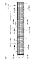
本実施形態で示すフェンスAは、図1及び図2に示すように、地面gに所定間隔を空けて立設された複数(図1において4本)の支柱bと、支柱b間に架設された複数(図1において3枚)のメッシュパネルa1~a3と、メッシュパネルa1、a2の上縁の上胴縁a10、a20に取り付けられた2本の笠木1、2とを備えており、道路側(以下「前側」という)と建物側(以下「後側」という)とを隔てるように立設されている。
[Fence configuration]
As shown in FIGS. 1 and 2, the fence A shown in the present embodiment is erected between a plurality of columns b (four in FIG. 1) erected at predetermined intervals on the ground g and the columns b. It is provided with a plurality of mesh panels a1 to a3 (three in FIG. 1) and two caps 1 and 2 attached to the upper furring strips a10 and a20 of the upper edges of the mesh panels a1 and a2. It is erected so as to separate the side (hereinafter referred to as "front side") and the building side (hereinafter referred to as "rear side").
本実施形態では、3枚のメッシュパネルa1~a3のうち、メッシュパネルa1、a2の上胴縁a10、a20に笠木1、2を設けた構成を示しているが、本発明では、メッシュパネルa3の上胴縁a30にも笠木を設けた構成としてもよい(図示せず)。
また、本実施形態では、笠木1、2同士を連続して隣接するように設けた構成を示しているが、本発明では、笠木1、2同士を離間させて設けた構成としてもよい。
また、笠木1、2は、上胴縁a10~a30と後述する下胴縁a11~a31との双方に設けてもよいし、下胴縁a11~a31のみに設けてもよい。
In the present embodiment, of the three mesh panels a1 to a3, the upper furring strips a10 and a20 of the mesh panels a1 and a2 are provided with the caps 1 and 2, but in the present invention, the mesh panel a3 is provided. The upper furring strip a30 may also be provided with a cap tree (not shown).
Further, in the present invention, the configuration in which the caps 1 and 2 are provided so as to be continuously adjacent to each other is shown, but in the present invention, the caps 1 and 2 may be provided so as to be separated from each other.
Further, the caps 1 and 2 may be provided on both the upper furring strips a10 to a30 and the lower furring strips a11 to a31 described later, or may be provided only on the lower furring strips a11 to a31.
メッシュパネルa1~a3は、図1及び図2に示すように複数の金属製の竪線材L1と横線材L2とを直交するように配置してなるものであり、図2に示すように、上縁の全域に上胴縁a10~a30が形成され、下縁の全域に下胴縁a11~a31が形成されている。
メッシュパネルa1~a3は、図3に示すように、それぞれ支柱bに対して固定具b1により固定され、隣合うメッシュパネルa1~a3の上胴縁a10~a30の側縁同士を連結具cを用いて連結し、下胴縁a11~a31の側縁同士を連結具cと同じ構成の連結具(図示せず)を用いて連結している。
上胴縁a10~a30及び下胴縁a11~a31は、前側へ突出するように形成された側面半円状に形成されている。
The mesh panels a1 to a3 are formed by arranging a plurality of metal vertical wire rods L1 and horizontal wire rods L2 so as to be orthogonal to each other as shown in FIGS. 1 and 2. Upper furring strips a10 to a30 are formed over the entire edge, and lower furring strips a11 to a31 are formed over the entire lower furring strip.
As shown in FIG. 3, the mesh panels a1 to a3 are fixed to the support columns b by the fixing tool b1, and the side edges of the upper furring strips a10 to a30 of the adjacent mesh panels a1 to a3 are connected to each other. The side edges of the lower furring strips a11 to a31 are connected to each other by using a connecting tool (not shown) having the same configuration as the connecting tool c.
The upper furring strips a10 to a30 and the lower furring strips a11 to a31 are formed in a semicircular side surface formed so as to project forward.
[笠木の構成]
笠木1、2は、図1~図3に示すように、左右方向に長尺な断面凹状に形成されたものであり、笠木1が左側のメッシュパネルa1の上胴縁a10に取り付けられ、笠木2が中央のメッシュパネルa2の上胴縁a20に取り付けられている。
笠木1、2は、図2及び図3に示すように、上胴縁a10、a20に前側(前側へ突出する側から被せるように嵌合させて固定されており、笠木1と笠木2同士が後述する固定板3を介して連結固定されている。
[Composition of Kasagi]
As shown in FIGS. 1 to 3, the caps 1 and 2 are formed in a concave shape having a long cross section in the left-right direction. 2 is attached to the upper furring strip a20 of the central mesh panel a2.
As shown in FIGS. 2 and 3, the caps 1 and 2 are fitted and fixed to the upper furring strips a10 and a20 so as to cover the front side (the side protruding to the front side), and the caps 1 and the caps 2 are fixed to each other. It is connected and fixed via a
上胴縁a10、a20に対する笠木1、2の固定構造は、図2~図6に示すように、笠木1、2に設けられた嵌合凹部10、11、20、21に嵌合された固定板3に対し、取付金具4を上胴縁a10、a20の後側から横線材L2を挟み込んで対面させると共に、取付金具4の後側からビス5を固定板3にねじ込むことで締結するものである。
嵌合凹部10、11は、笠木1の長手方向(左右方向)の全域にわたるように設けられており、図3(a)に示すように、上側の嵌合凹部10を下向き開放とし、下側の嵌合凹部11を上向き開放として、それぞれ前面部の後側に形成されている。
上側の嵌合凹部20及び下側の嵌合凹部21は、図3(b)に示すように、上側の嵌合凹部10及び下側の嵌合凹部11と、それぞれ同じ位置及び形状として形成されていると共に、左右方向で連続するように設けられている。
このような固定構造によって、笠木1、2の固定を後側(家屋側)から行うことができるため、前側(道路側)での歩行者の通行を妨げることを防ぐことができる。
また、図5及び図6に示すように、固定構造及び上胴縁a10、a20の突出部分が笠木1、2によって前側から見えないように隠されているため、フェンスAの前側の意匠性を笠木1、2により高めることができる。
As shown in FIGS. 2 to 6, the fixing structure of the caps 1 and 2 to the upper furring strips a10 and a20 is fixed fitted in the
The
As shown in FIG. 3B, the upper fitting recess 20 and the
With such a fixing structure, the caps 1 and 2 can be fixed from the rear side (house side), so that it is possible to prevent pedestrians from obstructing the passage on the front side (road side).
Further, as shown in FIGS. 5 and 6, the fixed structure and the protruding portions of the upper furring strips a10 and a20 are hidden by the caps 1 and 2 so as not to be seen from the front side, so that the design of the front side of the fence A is improved. It can be enhanced by Kasagi 1 and 2.
笠木1の左端部には、図3及び図5に示すように、小口キャップ12が取り付けられており、笠木1の左端部の全域及び上胴縁a10の左端部の全域を隠すようにしている。
小口キャップ12は、図7(a)に示すように、笠木1の左端部の全域及び上胴縁a10の全域を隠すカバー板12aと、笠木1の嵌合凹部10、11に左端部から挿し込む挿入板12bとを備えている。
カバー板12aは、笠木1の左端部及び上胴縁a10の左端部と正対し、挿入板12bは、笠木1の左右方向に沿うようにカバー板12aに対して突設されている。
小口キャップ12の固定構造は、図3及び図5に示すように、嵌合凹部10、11に嵌合された固定板3に対して上胴縁a10の後側からのねじ止めにより締結したものである。
As shown in FIGS. 3 and 5, a
As shown in FIG. 7A, the
The
As shown in FIGS. 3 and 5, the fixing structure of the
笠木2の右端部には、図3及び図6に示すように、中間小口キャップ13が取り付けられており、笠木2の右端部の全域を隠すようにしている。
中間小口キャップ13は、図7(b)に示すように、笠木2の右端部の全域を隠すと共に、上胴縁a20の横線材L2を通過可能な形状の切り欠き部130が形成されたカバー板13aと、笠木2の嵌合凹部20、21に右端部から挿し込む挿入板13bとを備えている。
カバー板13aは、笠木2の右端部と正対し、挿入板13bは、笠木2の左右方向に沿うようにカバー板13aに対して突設されている。
小口キャップ13の固定構造は、図3及び図6に示すように、嵌合凹部20、21に嵌合された固定板3に対して上胴縁a20の後側からのねじ止めにより締結したものである。
As shown in FIGS. 3 and 6, an
As shown in FIG. 7B, the
The
As shown in FIGS. 3 and 6, the fixing structure of the
笠木1の右端部と笠木2の左端部の取り合い構造は、笠木1の右端部と笠木2の左端部との間に連結ピース(図示せず)を介在させて連結する構造とすることで、笠木1と笠木2とを連続した一本の笠木構造にすることができる。
これによって、笠木1と笠木2とが一本の笠木構造として隣り合うメッシュパネルa1とメッシュパネルa2との間に架け渡されて、双方の上胴縁a10、a20に固定される
ため、隣り合うメッシュパネルa1とメッシュパネルa2との連結を強固することができる。
したがって、メッシュパネルa1とメッシュパネルa2との連結を強固なものとなるので、フェンスAの強度を高めることができる。
なお、笠木1、2は、当初から笠木1、2を設けるメッシュパネルa1~a3の枚数に対応する長さに合わせた長さとした一本構造としてもよい(図示せず)。
The connection structure between the right end of Kasagi 1 and the left end of Kasagi 2 is such that a connecting piece (not shown) is interposed between the right end of Kasagi 1 and the left end of Kasagi 2 to connect them. The Kasagi 1 and the Kasagi 2 can be made into a continuous Kasagi structure.
As a result, the cap tree 1 and the cap tree 2 are bridged between the adjacent mesh panel a1 and the mesh panel a2 as one cap tree structure and fixed to both upper furring strips a10 and a20, so that they are adjacent to each other. The connection between the mesh panel a1 and the mesh panel a2 can be strengthened.
Therefore, since the connection between the mesh panel a1 and the mesh panel a2 is strengthened, the strength of the fence A can be increased.
The caps 1 and 2 may have a single structure having a length corresponding to the number of mesh panels a1 to a3 on which the caps 1 and 2 are provided from the beginning (not shown).
笠木1、2は、以下の取付け構成により取付けられている。
その取付け構成は、笠木1、2内に配置した固定板3と、上胴縁a10、a20を境として笠木1、2と反対側の上胴縁a10、a20に配置した取付金具4を備えており、笠木1、2と上胴縁a10、a20は、固定板3と取付金具4で上胴縁a10、a20の横線材L2を挟着して固定してあると共に、一方の笠木1と他方の笠木2を連結してある。
また、他の取付け構成として、笠木1、2の形状を変えてフィン等を設けたような笠木とする場合、等笠木1、2内に固定板3を配置せずに、取付金具4を笠木1、2に直止めする構成とすることもできる(図示せず)。
すなわち、上胴縁a10、a20を境として笠木1、2と反対側の上胴縁a10、a20に配置した取付金具4を備え、取付金具4が一方のメッシュパネルa1の上胴縁a10と他方のメッシュパネルa2の上胴縁a20にまたがって配置されており、一方の笠木1と他方の笠木2を一方のメッシュパネルa1の上胴縁a10と他方のメッシュパネルa2の上胴縁a20に引き寄せて固定してある構成とすることもできる(図示せず)。
Kasagi 1 and 2 are attached by the following attachment configurations.
The mounting configuration includes a fixing
Further, as another mounting configuration, when the shape of the caps 1 and 2 is changed to provide a caps such as fins, the mounting
That is, the mounting
[固定板の構成]
固定板3は、図3及び図5、図6に示すように、上下の嵌合凹部10、11及び上下の嵌合凹部20、21に対して図3の奥行き方向に向かってスライドして嵌合されており、嵌合状態において、左右にスライド自在にされている。
上下の嵌合凹部10、11及び上下の嵌合凹部20、21に嵌合された固定板3を左右にスライドさせることにより、任意の位置で取付金具4とビス5とによる笠木1、2の固定を行うことができる。
笠木1、2の連結は、一枚の固定板3の一半部が笠木1に挿入され、他半部が笠木2に挿入されて連結されるため、笠木1、2の連結部分の強度を確保することができる。
[Structure of fixing plate]
As shown in FIGS. 3, 5, and 6, the fixing
By sliding the fixing
In the connection of Kasagi 1 and 2, one half of one
[取付金具の構成]
取付金具4は、図3及び図4に示すように、ビス5が貫通する上下のビス止め孔400、400の間に後側に凹ませた横線材L2を呑み込む凹部40と、下側に横線材L2に上側から引掛けるように略L形に形成された掛け部41とを備えている。
このような取付金具4は、上胴縁a10、a20の後側から横線材L2を呑み込ませると、凹部40が下側の横線材L2に引っ掛かり、手を離しても取付金具4が上胴縁a10、a20に保持されるようになっている。
これによって、小さな取付金具4を支えることなく、笠木1,2部分を支えることでビス5のねじ込み作業を行うことができるので、笠木1、2の取付作業を迅速に行うことができる。
また、凹部40に加えて、掛け部41も横線材L2に引っかかるようにしてあるので、笠木1、2部分に人が手をついたとき等の、回転止めができる。
[Structure of mounting bracket]
As shown in FIGS. 3 and 4, the mounting
When the horizontal wire L2 is swallowed from the rear side of the upper furring strips a10 and a20, the
As a result, the
Further, since the hanging
[笠木の取付け手順]
笠木1、2は、下記の取付け工程(第1工程~第4工程)により取り付けられる(図示せず)。
第1工程:笠木1、2の嵌合凹部10、11内に、真ん中の固定板3をスライドして入れる。
第2工程:真ん中の取付金具4の凹部40を横線材L2に引っ掛けて、真ん中の取付金具4と真ん中の固定板3を仮固定する。
第3工程:両端の固定板3をスライドして入れて、両端および真ん中の取付金具4と固定板3を本固定する。
第4工程:小口キャップ12を笠木1の左側の端部に取付けると共に、中間小口キャップ13を笠木2の右側の端部に取付ける。
この第1工程~第4工程により笠木1、2を取付けることができる。
[Kasagi installation procedure]
Kasagi 1 and 2 are attached by the following attachment steps (first step to fourth step) (not shown).
First step: The fixing
Second step: The
Third step: The fixing
Fourth step: The
Kasagi 1 and 2 can be attached by the first step to the fourth step.
以上の構成とするフェンスAは、笠木1、2を一本構造として上胴縁a10、a20に架け渡すように固定することによって、フェンスAの強度を高めることができると共に、前側からの意匠性を高めることができる。
しかも、笠木1、2の取付作業を迅速に行うことができるので、フェンスAの施工の効率化が期待できる。
The fence A having the above configuration can increase the strength of the fence A by fixing the caps 1 and 2 as a single structure so as to span the upper furring strips a10 and a20, and the design from the front side. Can be enhanced.
Moreover, since the installation work of the caps 1 and 2 can be performed quickly, the efficiency of the construction of the fence A can be expected to be improved.
以上、本発明に係る実施形態の建具を、図面を参照して詳述してきたが、具体的な構成は、これらの実施の形態に限られるものではなく、本発明の要旨を逸脱しない範囲の設計の変更等があっても本発明に含まれる。
また、前述の各実施形態は、その目的および構成等に特に矛盾や問題がない限り、互いの技術を流用して組み合わせることが可能である。
Although the fittings of the embodiments according to the present invention have been described in detail with reference to the drawings, the specific configuration is not limited to these embodiments and does not deviate from the gist of the present invention. Even if there is a design change or the like, it is included in the present invention.
Further, each of the above-described embodiments can be combined by diverting the techniques of each other as long as there is no particular contradiction or problem in the purpose and configuration thereof.
A: フェンス
b:支柱
c:連結具
1:笠木
2:笠木
3:固定板
4:取付金具
5:ビス
10:嵌合凹部
11:嵌合凹部
12:小口キャップ
13:中間小口キャップ
20:嵌合凹部
21:嵌合凹部
40:凹部
41:掛け部
400:ビス止め孔
a1:メッシュパネル
a2:メッシュパネル
a3:メッシュパネル
L1:竪線材
L2:横線材
a10:上胴縁
a20:上胴縁
a30:上胴縁
a11:下胴縁
a21:下胴縁
a31:下胴縁
b1:固定具
12a:カバー板
12b:挿入板
130:切り欠き部
13a:カバー板
13b:挿入板
g:地面
A: Fence b: Support c: Connector 1: Kasagi 2: Kasagi 3: Fixing plate 4: Mounting bracket 5: Screw 10: Fitting recess 11: Fitting recess 12: Edge cap 13: Intermediate edge cap 20: Fitting Recess 21: Fitting recess 40: Recess 41: Hanging part 400: Screw fixing hole a1: Mesh panel a2: Mesh panel a3: Mesh panel L1: Vertical wire L2: Horizontal wire a10: Upper furring strip a20: Upper furring strip a30: Upper furring strip a11: Lower furring strip a21: Lower furring strip a31: Lower furring strip b1:
Claims (1)
It has a mesh panel and a cap tree, and the mesh panel has one mesh panel and the other mesh panel adjacent to it, each with a furring strip at the top, one cap tree and the other adjacent cap tree. In the case of Kasagi, one Kasagi and the other Kasagi are fixed to the furring strip of one mesh panel and the furring strip of the other mesh panel, respectively, and one Kasagi and the other Kasagi are fixed. A fence featuring.
Priority Applications (1)
| Application Number | Priority Date | Filing Date | Title |
|---|---|---|---|
| JP2020174711A JP7556743B2 (en) | 2020-10-16 | 2020-10-16 | fence |
Applications Claiming Priority (1)
| Application Number | Priority Date | Filing Date | Title |
|---|---|---|---|
| JP2020174711A JP7556743B2 (en) | 2020-10-16 | 2020-10-16 | fence |
Publications (2)
| Publication Number | Publication Date |
|---|---|
| JP2022065911A true JP2022065911A (en) | 2022-04-28 |
| JP7556743B2 JP7556743B2 (en) | 2024-09-26 |
Family
ID=81387704
Family Applications (1)
| Application Number | Title | Priority Date | Filing Date |
|---|---|---|---|
| JP2020174711A Active JP7556743B2 (en) | 2020-10-16 | 2020-10-16 | fence |
Country Status (1)
| Country | Link |
|---|---|
| JP (1) | JP7556743B2 (en) |
Citations (8)
| Publication number | Priority date | Publication date | Assignee | Title |
|---|---|---|---|---|
| JPS5429529U (en) * | 1977-07-30 | 1979-02-26 | ||
| US4558851A (en) * | 1982-06-16 | 1985-12-17 | Asahi Wire Nets & Steel Ltd. | Fence of wire latticework |
| JPS6185669U (en) * | 1984-11-12 | 1986-06-05 | ||
| JPS6294263U (en) * | 1985-12-03 | 1987-06-16 | ||
| JP2005226374A (en) * | 2004-02-16 | 2005-08-25 | Sankyo Alum Ind Co Ltd | Mesh fence |
| JP2007100453A (en) * | 2005-10-06 | 2007-04-19 | Shikoku Chem Corp | Return bend portion |
| JP3201591U (en) * | 2015-10-06 | 2015-12-17 | 株式会社高岡ケージ工業 | Mesh panel with torso |
| EP3502379A1 (en) * | 2017-12-21 | 2019-06-26 | Generale Maatschappij voor Plastiek Internationaal naamloze vennootschap | Kit for assembling of a garden fence and packaging, storage and transport of kit and packaging |
-
2020
- 2020-10-16 JP JP2020174711A patent/JP7556743B2/en active Active
Patent Citations (8)
| Publication number | Priority date | Publication date | Assignee | Title |
|---|---|---|---|---|
| JPS5429529U (en) * | 1977-07-30 | 1979-02-26 | ||
| US4558851A (en) * | 1982-06-16 | 1985-12-17 | Asahi Wire Nets & Steel Ltd. | Fence of wire latticework |
| JPS6185669U (en) * | 1984-11-12 | 1986-06-05 | ||
| JPS6294263U (en) * | 1985-12-03 | 1987-06-16 | ||
| JP2005226374A (en) * | 2004-02-16 | 2005-08-25 | Sankyo Alum Ind Co Ltd | Mesh fence |
| JP2007100453A (en) * | 2005-10-06 | 2007-04-19 | Shikoku Chem Corp | Return bend portion |
| JP3201591U (en) * | 2015-10-06 | 2015-12-17 | 株式会社高岡ケージ工業 | Mesh panel with torso |
| EP3502379A1 (en) * | 2017-12-21 | 2019-06-26 | Generale Maatschappij voor Plastiek Internationaal naamloze vennootschap | Kit for assembling of a garden fence and packaging, storage and transport of kit and packaging |
Also Published As
| Publication number | Publication date |
|---|---|
| JP7556743B2 (en) | 2024-09-26 |
Similar Documents
| Publication | Publication Date | Title |
|---|---|---|
| JP4767881B2 (en) | Fence beam mounting structure | |
| RU154895U1 (en) | Dismountable SECTION OF THE FENDING DESIGN | |
| CN103003510A (en) | Illuminated double-profile fence post and associated fence structure | |
| JP4679435B2 (en) | Wiring storage structure for installations on the roof | |
| JP7431051B2 (en) | Simple structure | |
| KR102594889B1 (en) | Assembly type coupling socket, canopy frame and structure using the same | |
| US20060169965A1 (en) | Pre-fabricated fencing panels | |
| JP2006249677A (en) | Outdoor structure | |
| JP7556743B2 (en) | fence | |
| JP6760853B2 (en) | Structure | |
| KR100740856B1 (en) | Adjustable railing | |
| KR101819716B1 (en) | Assembling awning | |
| KR101474720B1 (en) | Guardrail Post of Deck | |
| JP4332521B2 (en) | Architectural exterior louver | |
| JP6465548B2 (en) | fence | |
| JP2021080692A (en) | Frame structure | |
| JP4954735B2 (en) | Fence and its installation method | |
| JP2021155918A (en) | Fence | |
| JP3253875U (en) | pergola | |
| JP6929082B2 (en) | Fence and fence construction method | |
| JP3122130U (en) | fence | |
| KR200392047Y1 (en) | A character fixed plate for guardrail | |
| JP2000297562A (en) | Mounting frame for fence decorative members | |
| JP2008144565A (en) | Beam attaching structure of shelf | |
| JP2023058815A (en) | fence |
Legal Events
| Date | Code | Title | Description |
|---|---|---|---|
| A621 | Written request for application examination |
Free format text: JAPANESE INTERMEDIATE CODE: A621 Effective date: 20230425 |
|
| A977 | Report on retrieval |
Free format text: JAPANESE INTERMEDIATE CODE: A971007 Effective date: 20240126 |
|
| A131 | Notification of reasons for refusal |
Free format text: JAPANESE INTERMEDIATE CODE: A131 Effective date: 20240130 |
|
| A521 | Request for written amendment filed |
Free format text: JAPANESE INTERMEDIATE CODE: A523 Effective date: 20240318 |
|
| A131 | Notification of reasons for refusal |
Free format text: JAPANESE INTERMEDIATE CODE: A131 Effective date: 20240507 |
|
| A521 | Request for written amendment filed |
Free format text: JAPANESE INTERMEDIATE CODE: A523 Effective date: 20240618 |
|
| TRDD | Decision of grant or rejection written | ||
| A01 | Written decision to grant a patent or to grant a registration (utility model) |
Free format text: JAPANESE INTERMEDIATE CODE: A01 Effective date: 20240903 |
|
| A61 | First payment of annual fees (during grant procedure) |
Free format text: JAPANESE INTERMEDIATE CODE: A61 Effective date: 20240912 |
|
| R150 | Certificate of patent or registration of utility model |
Ref document number: 7556743 Country of ref document: JP Free format text: JAPANESE INTERMEDIATE CODE: R150 |