JP2022064300A - Ophthalmologic apparatus - Google Patents
Ophthalmologic apparatus Download PDFInfo
- Publication number
- JP2022064300A JP2022064300A JP2021161183A JP2021161183A JP2022064300A JP 2022064300 A JP2022064300 A JP 2022064300A JP 2021161183 A JP2021161183 A JP 2021161183A JP 2021161183 A JP2021161183 A JP 2021161183A JP 2022064300 A JP2022064300 A JP 2022064300A
- Authority
- JP
- Japan
- Prior art keywords
- cheek
- subject
- pad
- cheek pad
- contact member
- Prior art date
- Legal status (The legal status is an assumption and is not a legal conclusion. Google has not performed a legal analysis and makes no representation as to the accuracy of the status listed.)
- Granted
Links
Images




Classifications
-
- A—HUMAN NECESSITIES
- A61—MEDICAL OR VETERINARY SCIENCE; HYGIENE
- A61B—DIAGNOSIS; SURGERY; IDENTIFICATION
- A61B3/00—Apparatus for testing the eyes; Instruments for examining the eyes
- A61B3/0083—Apparatus for testing the eyes; Instruments for examining the eyes provided with means for patient positioning
-
- A—HUMAN NECESSITIES
- A61—MEDICAL OR VETERINARY SCIENCE; HYGIENE
- A61B—DIAGNOSIS; SURGERY; IDENTIFICATION
- A61B3/00—Apparatus for testing the eyes; Instruments for examining the eyes
- A61B3/02—Subjective types, i.e. testing apparatus requiring the active assistance of the patient
- A61B3/028—Subjective types, i.e. testing apparatus requiring the active assistance of the patient for testing visual acuity; for determination of refraction, e.g. phoropters
-
- A—HUMAN NECESSITIES
- A61—MEDICAL OR VETERINARY SCIENCE; HYGIENE
- A61B—DIAGNOSIS; SURGERY; IDENTIFICATION
- A61B3/00—Apparatus for testing the eyes; Instruments for examining the eyes
- A61B3/10—Objective types, i.e. instruments for examining the eyes independent of the patients' perceptions or reactions
- A61B3/103—Objective types, i.e. instruments for examining the eyes independent of the patients' perceptions or reactions for determining refraction, e.g. refractometers, skiascopes
-
- A—HUMAN NECESSITIES
- A61—MEDICAL OR VETERINARY SCIENCE; HYGIENE
- A61B—DIAGNOSIS; SURGERY; IDENTIFICATION
- A61B3/00—Apparatus for testing the eyes; Instruments for examining the eyes
- A61B3/10—Objective types, i.e. instruments for examining the eyes independent of the patients' perceptions or reactions
- A61B3/13—Ophthalmic microscopes
Landscapes
- Life Sciences & Earth Sciences (AREA)
- Health & Medical Sciences (AREA)
- Medical Informatics (AREA)
- Biophysics (AREA)
- Ophthalmology & Optometry (AREA)
- Engineering & Computer Science (AREA)
- Biomedical Technology (AREA)
- Heart & Thoracic Surgery (AREA)
- Physics & Mathematics (AREA)
- Molecular Biology (AREA)
- Surgery (AREA)
- Animal Behavior & Ethology (AREA)
- General Health & Medical Sciences (AREA)
- Public Health (AREA)
- Veterinary Medicine (AREA)
- Eye Examination Apparatus (AREA)
Abstract
Description
本発明は、眼科装置に関する。 The present invention relates to an ophthalmic apparatus.
医師等の検者が、眼科装置を用いて、被検者の眼を検査する際には、被検者の頭部または顔の位置決めを行い、被検者の眼の位置を眼科装置に対して固定する必要がある。被検者の頭部を固定する技術は、例えば特許文献1および特許文献2に開示されている。
When an examiner such as a doctor examines the subject's eyes using an ophthalmologic device, the subject's head or face is positioned and the position of the subject's eyes is directed to the ophthalmic device. Need to be fixed. Techniques for fixing the head of a subject are disclosed in, for example,
特許文献1に開示された眼科装置用頭部固定装置は、被検者の額を当てて支持する額支持部と、被検者の頭部重量を頬骨部分で支える頬骨支持部と、を有する。額支持部と頬骨支持部とは、左右の支柱に連結され固定されている。このため、頬骨支持部の位置は、支柱に固定されている。
The head fixing device for an ophthalmic appliance disclosed in
特許文献2に開示された眼科装置は、筐体の開口部の上方に設けられた額当てと、筐体の開口部の下方に設けられた当接部材と、を備える。額当ては、被検者の額部により押圧され、被検者の顔面の凹凸に応じて眼科装置の光路の方向に移動する。当接部材は、頬骨付近により押圧され、被検者の顔面の凹凸に応じて眼科装置の光路の方向に移動する。額当てと当接部材とは、被検者の顔面を押し戻して被検者の顔面の凹凸に応じて移動し、作用反作用の釣り合いにより被検者の顔面を固定している。
The ophthalmic appliance disclosed in
ところで、特許文献1に開示された眼科装置用頭部固定装置では、被検者の額が額支持部で支持され、被検者の頬骨部分が頬骨支持部で支持される。また、特許文献2に開示された眼科装置では、被検者の額が額当てで支持され、被検者の頬骨付近が当接部材で支持される。つまり、特許文献1および特許文献2に開示された眼科装置は、顎受けを備えているわけではない。そのため、被検者の顎は、支持されていない。これにより、例えば自覚的検査などのように、被検者が検者の質問等に対して口頭で応答する必要がある場合、被検者は、被検眼の位置が眼科装置に対して固定されたままの状態で口頭により応答することができる。
By the way, in the head fixing device for an ophthalmic appliance disclosed in
しかし、前述したように、特許文献1に開示された頬骨支持部は、支柱に固定されている。また、被検者の左右の頬骨部分の間隔や位置は、被検者毎に異なる。このため、特許文献1に開示された眼科装置は、被検者の顔の大きさや形状に応じて被検者の左右の頬骨部分をより確実に支持し、被検眼の位置を固定したままの状態で被検者を口頭で応答可能にさせることが難しいという課題がある。
However, as described above, the cheekbone support portion disclosed in
また、特許文献2に開示された眼科装置では、当接部材は、被検者の顔面の凹凸に応じて眼科装置の光路の方向に移動する一方で、被検者の顔面に対して水平方向(すなわち左右方向)および上下方向には移動できない。そのため、特許文献2に開示された眼科装置は、被検者の顔の大きさや形状に応じて被検者の左右の頬骨部分をより確実に支持し、被検眼の位置を固定したままの状態で被検者を口頭で応答可能にさせることが難しいという課題がある。
Further, in the ophthalmic apparatus disclosed in
本発明は、前記課題を解決するためになされたものであり、被検者の顔の大きさや形状に応じて被検者の左右の頬骨部分をより確実に支持し、被検眼の位置を固定したままの状態で被検者を口頭で応答可能にさせることができる眼科装置を提供することを目的とする。 The present invention has been made to solve the above problems, and more reliably supports the left and right cheekbone portions of the subject according to the size and shape of the subject's face, and fixes the position of the eye to be inspected. It is an object of the present invention to provide an ophthalmic device capable of making a subject verbally responsive in the state of being left untouched.
前記課題は、被検者の被検眼を検査する眼科装置であって、前記被検者の額に当たる額当て部と、前記被検者の頬に当たる頬当て部と、を備え、前記頬当て部は、前記被検者の一方の前記頬を支持する第1頬当て体と、前記被検者の他方の前記頬を支持する第2頬当て体と、前記第1頬当て体と前記第2頬当て体とを水平方向において互いに近づく方向と遠ざかる方向とに開閉させる開閉機構部と、を有することを特徴とする本発明に係る眼科装置により解決される。 The subject is an ophthalmology device for inspecting a subject's eye, including a forehead pad portion corresponding to the subject's forehead and a cheek pad portion corresponding to the cheek pad portion of the subject, and the cheek pad portion. The first cheek pad that supports one of the cheeks of the subject, the second cheek pad that supports the other cheek of the subject, the first cheek pad and the second cheek. The problem is solved by the ophthalmic apparatus according to the present invention, which comprises an opening / closing mechanism portion for opening and closing the cheek rest body in a direction toward and away from each other in the horizontal direction.
本発明に係る眼科装置によれば、被検者の頭部もしくは顔は、第1支持部位である額当て部と、第2支持部位である第1頬当て体と、第3支持部位である第2頬当て体と、により、3点支持形式で支持される。第1頬当て体と第2頬当て体とが、被検者の顔の大小や固有の形状に応じて、開閉機構部により、水平方向において互いに近づく方向と遠ざかる方向とに開閉可能である。このため、被検者の被検眼の位置は、眼科装置に対して動かないように固定される。しかも、被検者の頭部もしくは顔は、顎が拘束されない状態で、不快感なく安定して支持される。これにより、本発明に係る眼科装置は、被検者の顔の大きさや形状に応じて被検者の左右の頬骨部分をより確実に支持し、被検眼の位置を固定したままの状態で被検者を口頭で応答可能にさせることができる。 According to the ophthalmic apparatus according to the present invention, the head or face of the subject is a forehead pad, which is a first support site, a first cheek pad, which is a second support site, and a third support site. It is supported by a second cheek pad and a three-point support form. The first cheek pad and the second cheek pad can be opened and closed in the horizontal direction in a direction toward and away from each other by the opening / closing mechanism portion according to the size of the face of the subject and the unique shape. Therefore, the position of the subject's eye to be inspected is fixed so as not to move with respect to the ophthalmic apparatus. Moreover, the head or face of the subject is stably supported without discomfort without the jaw being restrained. As a result, the ophthalmic apparatus according to the present invention more reliably supports the left and right cheekbone portions of the subject according to the size and shape of the subject's face, and is covered with the position of the subject's eye fixed. The examiner can be made verbally responsive.
本発明に係る眼科装置において、好ましくは、前記第1頬当て体は、前記一方の前記頬に当たる球体の第1当て部材を先端部に有し、前記第2頬当て体は、前記他方の前記頬に当たる球体の第2当て部材を先端部に有することを特徴とする。
本発明に係る眼科装置によれば、第1頬当て体の第1当て部材と、第2頬当て体の第2当て部材と、は、ともに球体であるので、被検者の頬骨部分の位置や形状に応じて被検者の左右の頬骨部分をより確実に支持することができる。また、第1当て部材および第2当て部材は、球体であるため、第1当て部材が被検者の一方の頬に直接当たるとともに第2当て部材が被検者の他方の頬に直接当たる場合であっても、不快感なく被検者の頭部もしくは顔を支持することができる。
In the ophthalmic apparatus according to the present invention, preferably, the first cheek pad has a first contact member of a sphere that hits one of the cheeks at the tip thereof, and the second cheek pad has the other one. It is characterized by having a second contact member of a sphere that hits the cheek at the tip.
According to the ophthalmic apparatus according to the present invention, since the first contact member of the first cheek pad and the second contact member of the second cheek pad are both spherical, the position of the cheekbone portion of the subject Depending on the shape and shape, the left and right cheekbones of the subject can be supported more reliably. Further, since the first contact member and the second contact member are spheres, the case where the first contact member directly hits one cheek of the subject and the second contact member directly hits the other cheek of the subject. Even so, the head or face of the subject can be supported without discomfort.
本発明に係る眼科装置において、好ましくは、前記開閉機構部は、前記第1頬当て体と前記第2頬当て体とを、鉛直方向の中心線に対して、前記水平方向に左右均等な角度で開閉可能であることを特徴とする。
本発明に係る眼科装置によれば、第1頬当て体と第2頬当て体とは、開閉機構部により水平方向に左右均等な角度で開閉できる。そのため、第1頬当て体と第2頬当て体とは、被検者の顔の大小や固有の形状に応じて、一方の頬と他方の頬をより一層安定して支持できる。
In the ophthalmic apparatus according to the present invention, preferably, the opening / closing mechanism portion makes the first cheek pad and the second cheek pad at an even angle in the horizontal direction with respect to the center line in the vertical direction. It is characterized by being able to open and close with.
According to the ophthalmic apparatus according to the present invention, the first cheek pad and the second cheek pad can be opened and closed horizontally at equal angles on the left and right by the opening / closing mechanism portion. Therefore, the first cheek pad and the second cheek pad can support one cheek and the other cheek more stably according to the size of the face of the subject and the unique shape.
本発明に係る眼科装置において、好ましくは、前記開閉機構部は、前記第1頬当て体と前記第2頬当て体とを、鉛直方向について互いに同じ高さ位置になるように移動可能であることを特徴とする。
本発明に係る眼科装置によれば、開閉機構部は、第1頬当て体と、第2頬当て体と、を眼科装置の鉛直方向について互いに同じ高さ位置になるように移動できる。そのため、第1頬当て体と第2頬当て体とは、被検者の顔の大小や固有の形状に応じて鉛直方向に移動しながら一方の頬と他方の頬とにそれぞれ位置決めされ、一方の頬と他方の頬をより一層安定して支持できる。
In the ophthalmic apparatus according to the present invention, preferably, the opening / closing mechanism portion can move the first cheek pad and the second cheek pad so as to be at the same height position with respect to each other in the vertical direction. It is characterized by.
According to the ophthalmic apparatus according to the present invention, the opening / closing mechanism portion can move the first cheek pad and the second cheek pad so as to be at the same height position with respect to each other in the vertical direction of the ophthalmic apparatus. Therefore, the first cheek pad and the second cheek pad are positioned on one cheek and the other cheek, respectively, while moving in the vertical direction according to the size of the subject's face and the unique shape. Can support one cheek and the other cheek more stably.
本発明に係る眼科装置において、好ましくは、前記開閉機構部は、前記第1頬当て体と前記第2頬当て体とを、水平方向に延びた軸を中心として前記鉛直方向に回転させることにより互いに前記同じ高さ位置になるように移動可能であることを特徴とする。
本発明に係る眼科装置によれば、開閉機構部は、第1頬当て体と第2頬当て体とを、水平方向に延びた軸を中心として眼科装置の鉛直方向に回転させることにより互いに同じ高さ位置になるように移動できる。このため、第1頬当て体と第2頬当て体とは、被検者の顔の大小や固有の形状に応じて鉛直方向に回転しながら一方の頬と他方の頬とにそれぞれ位置決めされ、一方の頬と他方の頬とをより一層安定して支持できる。
In the ophthalmic apparatus according to the present invention, preferably, the opening / closing mechanism portion rotates the first cheek pad and the second cheek pad in the vertical direction about a horizontally extending axis. It is characterized in that it can be moved so as to be at the same height position as each other.
According to the ophthalmic apparatus according to the present invention, the opening / closing mechanism portion is the same as each other by rotating the first cheek pad and the second cheek pad in the vertical direction of the ophthalmoscope about a horizontally extending axis. It can be moved to the height position. Therefore, the first cheek pad and the second cheek pad are positioned on one cheek and the other cheek while rotating in the vertical direction according to the size and unique shape of the subject's face. One cheek and the other cheek can be supported more stably.
本発明に係る眼科装置において、好ましくは、前記眼科装置は、自覚検査装置であることを特徴とする。
本発明に係る眼科装置によれば、被検者の被検眼の自覚検査を行う際に、被検者の顔の大小や固有の形状に応じて、眼科装置に対して被検眼の位置を安定して確実に位置決めしながら、顎と口とが拘束されることを回避できる。これにより、本発明に係る眼科装置は、被検者の被検眼の自覚検査を行う際に、被検者の顔の大きさや形状に応じて被検者の左右の頬骨部分をより確実に支持し、被検眼の位置を固定したままの状態で被検者を口頭で応答可能にさせることができる。
In the ophthalmic apparatus according to the present invention, preferably, the ophthalmic apparatus is a subjective examination apparatus.
According to the ophthalmic apparatus according to the present invention, when performing a subjective examination of the subject's eye, the position of the subject's eye is stabilized with respect to the ophthalmic apparatus according to the size of the subject's face and the unique shape. It is possible to prevent the jaw and the mouth from being restrained while ensuring the positioning. As a result, the ophthalmic apparatus according to the present invention more reliably supports the left and right cheekbone portions of the subject according to the size and shape of the subject's face when performing a subjective examination of the subject's eye. However, the subject can be made to respond verbally while the position of the subject's eye remains fixed.
本発明に係る眼科装置において、好ましくは、前記自覚検査装置は、吊り下げた状態で台座に取り付けられていることを特徴とする。
本発明に係る眼科装置によれば、自覚検査装置が台座に吊り下げられた状態であっても、被検者の被検眼の自覚検査を行う際に、被検者の顔の大小や固有の形状に応じて、眼科装置に対して被検眼の位置を安定して確実に位置決めしながら、顎と口とが拘束されることを回避できる。これにより、本発明に係る眼科装置は、吊り下げ型の自覚検査装置において被検眼の自覚検査を行う際に、被検者の顔の大きさや形状に応じて被検者の左右の頬骨部分をより確実に支持し、被検眼の位置を固定したままの状態で被検者を口頭で応答可能にさせることができる。
In the ophthalmic apparatus according to the present invention, preferably, the subjective examination apparatus is attached to a pedestal in a suspended state.
According to the ophthalmic apparatus according to the present invention, even when the subjective examination device is suspended from the pedestal, the size of the subject's face and the uniqueness of the subject's face when performing the subjective examination of the subject's eye are unique. Depending on the shape, the position of the eye to be inspected can be stably and reliably positioned with respect to the ophthalmologic device, and the jaw and mouth can be avoided from being restrained. As a result, the ophthalmic apparatus according to the present invention provides the left and right cheekbone portions of the subject according to the size and shape of the subject's face when performing the subjective examination of the subject's eye in the hanging type subjective examination device. It can be more reliably supported and the subject can be verbally responsive while the position of the subject remains fixed.
本発明に係る眼科装置において、好ましくは、前記自覚検査装置は、自覚屈折検眼と他覚屈折検眼とを行う他覚自覚検査装置であることを特徴とする。
本発明に係る眼科装置によれば、自覚屈性検眼と他覚屈折検眼とを行う際に、被検者の顔の大小や固有の形状に応じて、眼科装置に対して被検眼の位置を安定して確実に位置決めできる。顎と口は拘束されないので、被検者は口頭で応答することができる。このため、他覚屈折検眼と自覚屈性検眼とをスムーズに実施できる。
In the ophthalmic apparatus according to the present invention, preferably, the subjective test device is an objective subjective test device that performs a subjective refraction optometry and an objective refraction optometry.
According to the ophthalmic apparatus according to the present invention, when performing subjective flexion optometry and objective refraction optometry, the position of the optometry with respect to the ophthalmic apparatus is determined according to the size and unique shape of the subject's face. Stable and reliable positioning. Since the jaw and mouth are not restrained, the subject can respond verbally. Therefore, the objective refraction optometry and the subjective tropic optometry can be smoothly performed.
本発明に係る眼科装置において、好ましくは、前記頬当て部は、サポート部材によりベース部に対して着脱可能に取り付けられており、校正を行うための模型眼を装着する模型眼ホルダーが、前記サポート部材に代わって前記ベース部に取り付け可能とされてなることを特徴とする。
本発明に係る眼科装置によれば、頬当て部は、サポート部材によりベース部に対して着脱可能に取り付けられている。そして、模型眼を装着する模型眼ホルダーが、頬当て部を支持するサポート部材に代わってベース部に取り付け可能とされている。そのため、本発明に係る眼科装置の光学的な校正(補正)を確実に実施することができる。
In the ophthalmic apparatus according to the present invention, preferably, the cheek rest portion is detachably attached to the base portion by a support member, and the model eye holder for mounting the model eye for calibration is the support. It is characterized in that it can be attached to the base portion instead of the member.
According to the ophthalmic apparatus according to the present invention, the cheek rest portion is detachably attached to the base portion by a support member. The model eye holder on which the model eye is attached can be attached to the base portion in place of the support member that supports the cheek rest portion. Therefore, the optical calibration (correction) of the ophthalmic apparatus according to the present invention can be reliably performed.
本発明によれば、被検者の顔の形状に応じて被検者の左右の頬骨部分をより確実に支持し、被検眼の位置を固定したままの状態で被検者を口頭で応答可能にさせることができる眼科装置を提供することができる。 According to the present invention, the left and right cheekbones of the subject can be more reliably supported according to the shape of the subject's face, and the subject can respond verbally while the position of the subject's eye is fixed. It is possible to provide an ophthalmic device that can be made to.
以下に、本発明の好ましい実施形態を、図面を参照して詳しく説明する。
なお、以下に説明する実施形態は、本発明の好適な具体例であるから、技術的に好ましい種々の限定が付されているが、本発明の範囲は、以下の説明において特に本発明を限定する旨の記載がない限り、これらの態様に限られるものではない。また、各図面中、同様の構成要素には同一の符号を付して詳細な説明は適宜省略する。
Hereinafter, preferred embodiments of the present invention will be described in detail with reference to the drawings.
Since the embodiments described below are suitable specific examples of the present invention, various technically preferable limitations are attached, but the scope of the present invention is particularly limited to the present invention in the following description. Unless otherwise stated, the present invention is not limited to these aspects. Further, in each drawing, the same components are designated by the same reference numerals, and detailed description thereof will be omitted as appropriate.
(第1実施形態)
(本発明の実施形態に係る眼科装置の一例の概要)
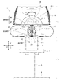
図1は、本発明の実施形態に係る眼科装置の一例である両眼他覚自覚検査装置を示す正面図である。
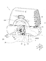
図2は、図1に示す両眼他覚自覚検査装置を示す斜視図である。
なお、図2では台座の一部の図示を省略している。
(First Embodiment)
(Summary of an example of an ophthalmic apparatus according to an embodiment of the present invention)
FIG. 1 is a front view showing a binocular objective awareness test device which is an example of an ophthalmic device according to an embodiment of the present invention.
FIG. 2 is a perspective view showing the binocular objective awareness test device shown in FIG.
In FIG. 2, a part of the pedestal is not shown.
図1および図2に示す両眼他覚自覚検査装置1は、検査装置本体2と、台座3とを備える。本実施形態に係る両眼他覚自覚検査装置1は、本発明の「眼科装置」の一例である。検査装置本体2は、台座3に支持されている。台座3は、床面に置かれる平板型の基部4と、支柱部分5、6と、テーブル7と、を有する。検査装置本体2は、支柱部分5の上端部に対して、吊り下げられた状態で設けられている。好ましくは、検査装置本体2は、支柱部分5に対して着脱可能に固定されている。本明細書においては、両眼他覚自覚検査装置1の左右方向をX方向で示し、両眼他覚自覚検査装置1の上下方向(すなわち鉛直方向)をY方向で示し、両眼他覚自覚検査装置1の前後方向(奥行方向)をZ方向で示している。
The binocular objective
図1および図2に示すように、両眼他覚自覚検査装置1の検査装置本体2は、第1接眼部11と、第2接眼部12と、本体ベース部13と、頭部固定装置20と、を有する。第1接眼部11は、被検者側から見て(図1の紙面垂直方向から見て)頭部固定装置20の右側に設けられ、被検者の右眼に視標等を提示したり被検者の右眼の特性に関する情報を取得したりする。第2接眼部12は、被検者側から見て(図1の紙面垂直方向から見て)頭部固定装置20の左側に設けられ、被検者の左眼に視標等を提示したり被検者の左眼の特性に関する情報を取得したりする。第1接眼部11と第2接眼部12と本体ベース部13とには、検査光学系等が設けられている。両眼他覚自覚検査装置1は、被検者の両眼について同時他覚的屈折測定機能と、被検者の両眼について同時自覚的屈折測定機能と、を有する。第1接眼部11と第2接眼部12とは、本体ベース部13の下部に設けられている。第1接眼部11と第2接眼部12との間には、空間部14が設けられている。本体ベース部13は、被検者の頭部のうち額面よりも上の部分を避けるために、凹状の曲面部分13Hを有する。
As shown in FIGS. 1 and 2, the inspection device
ここで、他覚的屈折検査とは、被検者の感覚を無視した検査である。他覚的屈折検査によれば、近視度や遠視度等の検査項目を、幼児や意識の無い被検者でも検査可能である。自覚的屈折検査とは、被検者の感覚を重視した検査である。自覚的屈折検査では、近視度や遠視度等の検査項目について、被検者の口頭による応答が必要であるので、幼児や意識の無い被検者については検査を行うことが困難である。両眼他覚自覚検査装置1では、両眼について、同時に他覚的屈折検査を行い、他覚的屈折検査が終了すると、他覚的屈折検査を参考にして、医師等の検者と被検者との口頭の応答による対話式の自覚的屈折検査が行われる。
Here, the objective refraction test is a test that ignores the sensation of the subject. According to the objective refraction test, inspection items such as myopia and hyperopia can be inspected even by infants and unconscious subjects. The subjective refraction test is a test that emphasizes the senses of the subject. In the subjective refraction test, it is difficult to perform the test for infants and unconscious subjects because it is necessary for the subject to make an oral response to the test items such as myopia and hyperopia. The binocular objective
なお、眼科検査の際に被検者の応答が必要なケース、すなわち被検者が口頭で応答するしかないケースとしては、自覚応答の必要な検査(自覚屈折検査、視機能検査、視野検査)、固視目標に関する応答(固視目標も中央、周辺、記号、視標、図、画像、映像等が存在する。)、検者からの質問に対する応答、被検者の体調状態の確認(例えば「眠いですか?」、「瞼が垂れ下がっていますよ?」、「気分は大丈夫ですか?」など)に対する応答、および被検者から検者への問いかけ(例えば「疲れました。」、「一休みしたいです。」など)等がある。 In addition, in the case where the subject's response is required at the time of ophthalmic examination, that is, the case where the subject has no choice but to respond verbally, the examination requiring a subjective response (awareness refraction test, visual function test, visual field test) , Response to the fixative target (the fixative target also has center, periphery, symbols, optotypes, figures, images, videos, etc.), response to questions from the examiner, confirmation of the physical condition of the subject (for example) Responses to "Are you sleepy?", "Your eyelids are hanging?", "Are you feeling okay?", And questions from the subject to the examiner (eg, "I'm tired.", "I'm tired." I want to take a rest. "And so on.
(頭部固定装置20)
次に、頭部固定装置20の構造を説明する。
図3は、本実施形態の頭部固定装置を拡大して示す斜視図である。
図4は、本実施形態の頭部固定装置を示す斜視図である。
(Head fixing device 20)
Next, the structure of the
FIG. 3 is an enlarged perspective view showing the head fixing device of the present embodiment.
FIG. 4 is a perspective view showing the head fixing device of the present embodiment.
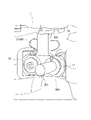
図1および図2に示すように、頭部固定装置20は、両眼他覚自覚検査装置1の空間部14に設けられている。具体的には、図1および図2に示すように、頭部固定装置20は、両眼他覚自覚検査装置1の本体ベース部13の空間部14において、Y方向に沿って吊り下げられるようにして配置されている。図1および図3に示すように、頭部固定装置20は、金属製あるいはプラスチック製であり、額当て部30と、頬当て部40と、棒状のサポート部材55と、を有する。
As shown in FIGS. 1 and 2, the
<額当て部30>
まず、図1および図3を参照して、頭部固定装置20の額当て部30について説明する。額当て部30は、被検者の額に当たって額を支持する部分であり、額当て面31と、棒状の支持部材32と、を有する。額当て面31は、被検者の額の曲面形状に合うように形成され、被検者の額を支持できるように例えば凹状の曲面を有している。図3に示すように、支持部材32の一端部33は、額当て面31の背面に連結されている。好ましくは、額当て面31は、支持部材32の一端部33に対して角度を変更可能なように取り付けられている。これにより、額当て面31は、被検者の固有の顔のサイズや形状に応じて被検者の額を当たり、額を安定して支持できる。
<
First, the
図3に示すように、支持部材32は、本体ベース部13のベース連結部15から下方手前側に伸びるようにしてベース連結部15に固定されている。支持部材32の他端部34は、ベース連結部15に対して、例えばネジ等により固定されている。好ましくは、支持部材32は、ベース連結部15に対して着脱可能に固定されている。これにより、額当て部30は、両眼他覚自覚検査装置1のメンテナンス時等において、サポート部材55とは別に取り外し可能とされている。
As shown in FIG. 3, the
額当て面31には、被検者が額を額当て面31に当てた時に、肌触りが良く、生体適合性を有する材料の部材、例えばゴム膜、シリコン膜、不織布等の部材が着脱可能に貼り付けられていても良い。これにより、被検者が代わる毎に検者が額当て面31に貼り付けられた部材を交換して衛生的な配慮をすることで、被検者は、不快感なく額を額当て面31に当てて額を支持することができる。
When the subject puts the forehead on the
<頬当て部40>
次に、図3および図4を参照して、頭部固定装置20の頬当て部40について説明する。
頬当て部40は、被検者の左右の頬骨部分に同時に当たって左右の頬骨部分を支持する部分である。頬当て部40は、第1頬当て体41と、第2頬当て体42と、頬当て部の開閉機構部50と、を有する。第1頬当て体41は、被検者の一方の頬である右頬に当たることで右頬を支持する。第2頬当て体42は、被検者の他方の頬である左頬に当たることで左頬を支持する。
<
Next, the
The
図4に示すように、第1頬当て体41は、軸部43と、球体の第1当て部材51と、を有する。球体の第1当て部材51は、軸部43の先端部に対して固定されている。同様にして、第2頬当て体42は、軸部44と、球体の第2当て部材52と、を有する。球体の第2当て部材52は、軸部44の先端部に対して固定されている。第1当て部材51および第2当て部材52が、軸部43,44のそれぞれに対して、着脱可能に固定されている場合には、検者は、衛生上の観点から、必要に応じたタイミングで、例えば被検者が代わる毎に、第1当て部材51および第2当て部材52を交換することができる。例えば、第1当て部材51および第2当て部材52には、メネジが形成されている。一方で、軸部43,44の先端部には、オネジが形成されている。これにより、第1当て部材51および第2当て部材52は、軸部43,44のそれぞれに対して着脱可能に固定される。なお、第1頬当て体41と第2頬当て体42とは、互いに同じ構造体であってもよい。また、軸部43と球体の第1当て部材51とは、互いに一体形成されていてもよい。さらに、軸部44と球体の第2当て部材52とは、互いに一体形成されていてもよい。
As shown in FIG. 4, the
第1当て部材51および第2当て部材52は、球体であるため、被検者の頬骨部分の位置や形状に応じて被検者の左右の頬骨部分をより確実に支持することができる。また、第1当て部材51および第2当て部材52は、球体であるため、第1当て部材51が被検者の右頬の頬骨の位置に直接当たるとともに、第2当て部材52が被検者の左頬の頬骨の位置に直接当たる場合であっても、不快感なく被検者の頭部もしくは顔を支持することができる。被検者の顔面に直接当たる第1当て部材51および第2当て部材52の材質としては、被検者への生体的な影響が少なく生体適合性を有するとともに比較的柔らかい材料、例えばシリコン等のゴムを用いた弾性材料が挙げられる。
Since the
次に、図4および図5を参照して、頭部固定装置20の頬当て部の開閉機構部50を説明する。
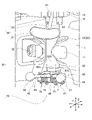
図5は、本実施形態の頭部固定装置を上方向から眺めたときの平面図である。
Next, the opening /
FIG. 5 is a plan view of the head fixing device of the present embodiment when viewed from above.
頬当て部40の開閉機構部50は、第1頬当て体41と第2頬当て体42とが、互いに近づく方向R1、R1と、互いに遠ざかる方向R2と、に同期して左右均等に開閉可能になるように、第1頬当て体41と第2頬当て体42とを支持している。近づく方向R1、R1と遠ざかる方向R2とは、互いに反対方向である。しかも、頬当て部40の開閉機構部50は、第1頬当て体41と第2頬当て体42とを、図4に示す回転方向R3に沿って上下方向(Y-Z平面内)において互いに同じ位置に回転させる。
The opening /
頬当て部40の開閉機構部50は、第1頬当て体41と、第2頬当て体42と、を例えば水平方向(X-Z平面内)で左右均等に開閉可能にするために、水平方向均等開閉機構60を有する。水平方向均等開閉機構60は、第1頬当て体41と、第2頬当て体42と、を鉛直方向の中心線であるY方向の軸を中心にして、それぞれ例えば水平方向に左右均等な角度で開閉可能である。
The opening /
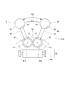
図4および図5を参照して、水平方向均等開閉機構60の好ましい構造例を説明する。
水平方向均等開閉機構60は、基部65と、第1回転体61と、第2回転体62と、を有する。基部65は、ほぼ扇型の上板65Aと下板65Bと側板65C、65Dと背面板65Eとから作られており、前面開口部66を有する。基部65は、第1回転体61と第2回転体62とをそれぞれ回転可能に支持しており、第1回転体61と第2回転体62とを内部において並べて収容している。
A preferred structural example of the horizontal uniform opening /
The horizontal uniform opening /
図5に示すように、第1回転体61および第2回転体62は、同じ構造体である。第1回転体61は、基部65内において、回転中心軸61Lを中心に回転可能に支持されている。同様にして、第2回転体62は、基部65内において、回転中心軸62Lを中心にして回転可能に支持されている。図5に示すように、第1回転体61は、歯車71と、円形の取付部73と、を有する。第2回転体62は、歯車72と、円形の取付部74と、を有する。
As shown in FIG. 5, the first
図5に示すように、歯車71,72は、互いに同じ歯数を有し、互いに同じ大きさの歯を有する。歯車71,72は、互いに噛み合っている。円形の取付部73は、歯車71の上に固定されており、軸部43を直径方向に沿って固定している。同様にして、円形の取付部74は、歯車72の上に固定されており、軸部44を直径方向に沿って固定している。これにより、第1当て部材51と第2当て部材52とは、被検者の右頬M1(図6および図7参照)と左頬M2(図6および図7参照)とにそれぞれ当たる際には、右頬M1と左頬M2とのそれぞれの位置に合わせて、互いに近づく方向R1、R1および遠ざかる方向R2に、左右均等に開閉可能である。第1頬当て体41の第1当て部材51と、第2頬当て体42の第2当て部材52と、が左右均等に開くことで、被検者の顔や頭部が傾いて支持されることを抑えることができる。
As shown in FIG. 5, the
図4および図5に示すように、頬当て部40の開閉機構部50は、水平方向均等開閉機構60に加えて、上下方向回転機構80をさらに有する。上下方向回転機構80は、棒状あるいは筒状のサポート部材55の下端部55Dに固定されていて、水平方向均等開閉機構60を、回転方向R3に沿って上下方向(Y-Z平面内)において旋回可能に支持している。
As shown in FIGS. 4 and 5, the opening /
図5に示すように、上下方向回転機構80は、ほぼ逆U字型の取付具81を有する。取付具81はサポート部材55の下端部55Dに固定されている。取付具81は、調整ネジ82を有している。調整ネジ82は、水平方向均等開閉機構60の突出部69を取付具81内に支持している。例えば検者等が専用工具等により調整ネジ82を回すことで、水平方向均等開閉機構60の全体が、回転方向R3に沿って上下方向(Y-Z平面内)において旋回する。これにより、第1頬当て体41の第1当て部材51と第2頬当て体42の第2当て部材52は、取付具81に対して、水平方向に延びた上下旋回中心軸80Lを中心としてR3方向に互いに均等に上下動して、上下方向(Y-Z平面内)において互いに同じ位置に位置決めされる。また、頬当て部40が不要な場合には、検者等は、水平方向均等開閉機構60の全体を回転方向R3に沿って例えば下方向に旋回させることにより、頬当て部40を検者および被検者から退避させることができる。
As shown in FIG. 5, the
このように、水平方向均等開閉機構60と一体になっている第1頬当て体41の第1当て部材51と第2頬当て体42の第2当て部材52とがR3方向に旋回する際には、左右の第1当て部材51と第2当て部材52とのY方向についての高さ位置は、互いに同じになっている。つまり、水平方向均等開閉機構60の全体が、図1に示す両眼他覚自覚検査装置1の上下方向について、上下方向回転機構80により、水平方向に延びた上下旋回中心軸80Lを中心としてR3方向に回転することで、第1当て部材51と第2当て部材52は、互いに同じ高さ位置に配置される。これにより、被検者の右頬M1および左頬M2は、球体の第1当て部材51と第2当て部材52とにより、眼科装置の上下方向(Y方向)について同じ高さ位置に支持される。また、被検者の顔が傾むくことを抑えつつ、被検者の右頬M1および左頬M2を不快感なく安定して支持することができる。上下方向回転機構80が、第1頬当て体41と第2頬当て体42とを、眼科装置の上下方向(Y方向)について互いに同じ高さ位置になるように均等に移動できるので、第1頬当て体41と第2頬当て体42は、被検者の顔の大小や固有の形状に応じて上下方向に移動しながら右頬M1と左頬M2とを互いに同じ高さの位置に位置決めできる。これにより、本実施形態に係る両眼他覚自覚検査装置1は、右頬M1と左頬M2とをより一層安定して支持できる。
In this way, when the
(頭部固定装置20の使用例)
次に、被検者が、図1に示す両眼他覚自覚検査装置1を用いて、両眼の他覚屈折検査と自覚屈折検査とを行う際に、頭部固定装置20が、被検者の頭部もしくは顔面を両眼他覚自覚検査装置1に対して動かないように支持することで、被検眼の位置を固定する様子の例を、図6~図8を参照して説明する。
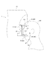
図6は、本実施形態の頭部固定装置が被検者の頭部もしくは顔面を支持している様子の例を示す模式図である。
図7は、被検者の顔面の額と右頬と左頬との支持状態を示す模式図である。
図8は、被検者の頭蓋骨の例を示す模式図である。
なお、図8(A)は、被検者の頭蓋骨を示す側面図である。図8(B)は、被検者の頭蓋骨を正面から見た平面図である。
(Example of using the head fixing device 20)
Next, when the subject performs the binocular objective refraction test and the subjective refraction test using the binocular objective
FIG. 6 is a schematic view showing an example in which the head fixing device of the present embodiment supports the head or face of the subject.
FIG. 7 is a schematic view showing a support state between the forehead of the face of the subject and the right cheek and the left cheek.
FIG. 8 is a schematic view showing an example of the skull of a subject.
Note that FIG. 8A is a side view showing the skull of the subject. FIG. 8B is a plan view of the skull of the subject as viewed from the front.
図6において、額当て部30の額当て面31は、被検者100の額101に当たって支持する。額当て面31は、被検者100の額101の曲面形状に合うようにして支持できる。額当て面31は、好ましくは支持部材32の一端部33に対して角度の変更が可能なように取り付けられている。被検者100の固有の顔のサイズや形状に応じて、額当て面31は被検者100の額101に当たって安定して支持できる。しかも、第1当て部材51と第2当て部材52とは、球体であるため、第1当て部材51が被検者100の右頬M1に直接当たるとともに、第2当て部材52が被検者100の左頬M2に直接当たる場合であっても、不快感なく被検者100の頭部もしくは顔を支持することができる。
In FIG. 6, the
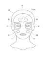
図7では、被検者100の顔面において、額当て面31が額101に当たる位置と、第1当て部材51と第2当て部材52とのそれぞれが右頬M1と左頬M2とのそれぞれに当てる位置と、第1接眼部11と第2接眼部12とのそれぞれが右側の被検眼E1および左側の被検眼E2とのそれぞれに接近する位置を示している。被検者100の頭部もしくは顔面は、額当て面31と第1当て部材51と第2当て部材52とにより、3点支持形式で支持されている様子を示している。
In FIG. 7, on the face of the subject 100, the position where the
図8に示す頭蓋骨では、図6に示す額当て面31は、被検者の額101の位置の骨部分(前頭骨の部分)に当たって支持し、図6に示す第1当て部材51と第2当て部材52とは、右頬M1の頬骨201の部分と左頬M2の頬骨202の部分に当たって支持する。これにより、頭部固定装置20は、下顎骨の部分を介することなく前頭骨の部分および胸骨の部分において、被検者の頭部もしくは顔面を安定して支持することができる。
In the skull shown in FIG. 8, the
これにより、被検者100の頭部もしくは顔面は、第1支持部位である額当て面31と、第2支持部位である第1当て部材51と、第3支持部位である第2当て部材52と、により、3点支持形式で安定して支持される。第1頬当て体41と第2頬当て体42とが、被検者の顔の大小や固有の形状に応じて、頬当て部40の開閉機構部50により、互いに近づく方向R1と遠ざかる方向R2とに開閉可能である。このため、図7に示す被検者100の被検眼E1、E2の位置は、眼科装置である両眼他覚自覚検査装置1に対して動かないように安定して固定される。しかも被検者の頭部もしくは顔面は、顎が拘束されない状態で、不快感なく安定して支持される。これにより、頭部固定装置20は、被検者100の顔面の大小や固有の形状に応じて、両眼他覚自覚検査装置1に対して被検眼E1、E2の位置を、3点支持方式で安定して確実に位置決めできる。しかも、顎と口は拘束されないので、被検者100は眼科検査時に口頭で応答することができ、他覚屈折検眼と自覚屈性検眼とをスムーズに実施できる。
As a result, the head or face of the subject 100 has a
このように、図4に示す頭部固定装置20は、被検眼E1、E2の位置が両眼他覚自覚検査装置1に対して動かないように被検者の頭蓋骨を3点支持方式で安定して支持することができる。被検者の顎と口とは、拘束されておらず自由状態である。このため、被検者は、検者の質問等に対して自由に口頭で応答することができる。以上より、本実施形態に係る眼科装置は、被検者の顔の大きさや形状に応じて被検者の左右の頬骨201、202の部分をより確実に支持し、被検眼の位置を固定したままの状態で被検者を口頭で応答可能にさせることができる。また、頭蓋骨が3点支持方式で支持されるので、両眼他覚自覚検査装置1による検査の際に、被検者の被検眼の位置が保持されやすい。
As described above, the
左右の位置にある第1当て部材51と第2当て部材52とは、両眼他覚自覚検査装置1の上下方向であるY方向に関して互いに同じ高さの位置に支持され、しかもY方向を中心にして例えば水平方向に左右均等な角度で開くことができる。このため、第1当て部材51と第2当て部材52は、被検者の顔を傾かないようにしてより一層安定して支持できる。また、被検者は、球体の第1当て部材51を右頬M1に当て、球体の第2当て部材52を左頬M2に当てる際に、被検者にとって気持ちの良いと思われる位置に球体の第1当て部材51と第2当て部材52とを自由に動かすことができる。第1当て部材51と第2当て部材52とは、被検者が頬で押すと移動する。
The
図1と図2に示すように、本実施形態の頭部固定装置20は、眼科装置の一例である両眼他覚自覚検査装置1に用いられている。被検者が口頭で応答する必要がある眼科装置では、検者が被検者から離れた位置で眼科検査を行うと、被検者の状態についての情報が得られにくいことが増える。例えば、検者がインターネットのような情報通信網を経由して遠隔式で眼科検査を行ったり、ソーシャルディスタンスを保つために、検者と被検者とが離れて検査を行ったりする機会が増える。
As shown in FIGS. 1 and 2, the
頭部固定装置20を用いることで、被検者は、顎と口が拘束されずに自由になる。そのため、検者は、被検者に対して問いかけることで、被検者に口頭による音声応答をしてもらうことができる。本実施形態の頭部固定装置20は、今後期待されるリモート検査(遠隔操作による検査)で要求される会話をしながら、眼科装置に対して被検眼の固定が可能になり、通常用いられている各種の眼科装置に適用することができる。
By using the
これに対して、従来用いられている眼科装置において顎受けだけを使用する場合には、顎受けは、被検者の顔の形状によっては、顎を1点で支持しているので、被検者の顔の位置、すなわち被検眼の位置を必ずしも安定して支持できない。例えば、被検者が歯を食いしばっている状態、口が半開きの状態、口が大きく開いている状態等の様々な状態の顎を顎受けに載せても、顔の位置は必ずしも安定しないことがある。しかも、顎が顎受けにより拘束されてしまうので、被検者は口頭による応答が困難である。
また、従来用いられている眼科装置において額当てのみを使用する場合には、被検者の顔の形状によっては、被検者の頭部が1点で支持される場合がある。そうすると、被検者の顔の位置、すなわち被検眼の位置が必ずしも安定しない。
On the other hand, when only the chin rest is used in the conventionally used ophthalmic apparatus, the chin rest supports the chin at one point depending on the shape of the subject's face, so that the subject is examined. The position of the person's face, that is, the position of the eye to be inspected, cannot always be stably supported. For example, even if the subject puts his chin on the chin rest in various states such as clenching his teeth, half-open mouth, and wide-open mouth, the position of his face may not always be stable. be. Moreover, since the jaw is restrained by the jaw holder, it is difficult for the subject to respond verbally.
Further, when only the forehead pad is used in the conventionally used ophthalmic apparatus, the head of the subject may be supported at one point depending on the shape of the face of the subject. Then, the position of the subject's face, that is, the position of the subject's eye, is not always stable.
図9は、模型眼ホルダーが図3に示す頭部固定装置に代えて装着されている例を示す斜視図である。
模型眼ホルダー300は、両眼他覚自覚検査装置1を生産して出荷する前に装着される。模型眼ホルダー300は、両眼他覚自覚検査装置1の光学的な校正(補正)を行う校正原器(補正原器)である。近視や遠視等のレンズのような模型眼301が装着されることで、模型眼301に基づいて光学系の補正を行って両眼他覚自覚検査装置1の検査用のソフトウェアの書き込みを行うことができる。
FIG. 9 is a perspective view showing an example in which the model eye holder is attached in place of the head fixing device shown in FIG.
The
図9において、模型眼ホルダー300が取付板302を用いてベース連結部15に対して、例えばネジ止めにより取り付けられる。これにより、模型眼ホルダー300は、模型眼301を両眼他覚自覚検査装置1に取付ける装置として機能する。模型眼ホルダー300は、模型眼301を用いて、両眼他覚自覚検査装置1の光学的な校正(補正)を行うことができる。その後、両眼他覚自覚検査装置1が実際に出荷される際には、模型眼ホルダー300が外され、図3に示す頭部固定装置20のサポート部材55の上端部が、ベース連結部15に取り付けられる。このように、眼科装置の校正(補正)を行うための模型眼301を両眼他覚自覚検査装置1に取付けるために、模型眼ホルダー300が取り付け可能とされている。
In FIG. 9, the
(第2実施形態)
次に、図10を参照して、本発明の第2実施形態に係る眼科装置を説明する。
図10は、本発明の第2実施形態に係る眼科装置の頭部固定装置を示す平面図である。
図5に示す第1実施形態の頭部固定装置20では、第1回転体61の歯車71と第2回転体62の歯車72とが互いに噛み合っている。これに対して、図10に示す第2実施形態の頭部固定装置20Aでは、第1回転体61と第2回転体62とは歯車ではなく、リング状の摩擦材61T、62Tを有している。第1回転体61の摩擦材61Tと第2回転体62の摩擦材62Tとは、所定の力で互いに突き当たっている。そして、第1回転体61と第2回転体62とは、互いに反対方向に回転する。これにより、図10に示す頭部固定装置20Aでは、第1頬当て体41と第2頬当て体42とが、互いに近づく方向R1、R1と遠ざかる方向R2とに同期して左右均等に開閉可能に支持されている。
(Second Embodiment)
Next, the ophthalmic apparatus according to the second embodiment of the present invention will be described with reference to FIG.
FIG. 10 is a plan view showing a head fixing device of the ophthalmic device according to the second embodiment of the present invention.
In the
(第3実施形態)
次に、図11を参照して、本発明の第3実施形態に係る眼科装置を説明する。
図11は、本発明の第3実施形態に係る眼科装置の頭部固定装置を示す側面図である。図4と図5に示す第1実施形態に係る頭部固定装置20では、頬当て部40の開閉機構部50は、水平方向均等開閉機構60に加えて、さらに上下方向回転機構80を有する。これに対して、図11に示す第3実施形態の頭部固定装置20Bでは、頬当て部40の開閉機構部50は、水平方向均等開閉機構60に加えて、さらに上下方向移動機構180を有する。上下方向移動機構180は、筒状の移動体181と、移動体181をサポート部材55の下端部55Dの任意の高さ位置に固定するための留めネジ182と、を有する。移動体181は、水平方向均等開閉機構60を固定している。
(Third Embodiment)
Next, the ophthalmic apparatus according to the third embodiment of the present invention will be described with reference to FIG.
FIG. 11 is a side view showing the head fixing device of the ophthalmic device according to the third embodiment of the present invention. In the
サポート部材55は、筒状の移動体181内を通過している。検者は、留めネジ182を緩めることで、手動で水平方向均等開閉機構60をY方向に沿って直線移動でき、留めネジ182を締めることで、水平方向均等開閉機構60を任意の高さ位置に固定できる。これにより、上下方向移動機構180のようなより簡単な機構を採用しても、被検者の右頬と左頬とは、球体の第1当て部材51と第2当て部材52とにより、互いに同じ高さ位置において安定して支持される。
The
(他の実施形態)
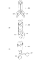
図12は、本発明の他の実施形態に係る眼科装置の頬当て部を示す模式図である。
図3から図5に示す本発明の第1実施形態に係る眼科装置では、頬当て部40の第1頬当て体41の第1当て部材51と第2頬当て体42の第2当て部材52は、ともに球体である。これに対して、図12(A)に示す実施形態の頬当て部40Aでは、第1当て部材351と第2当て部材352とは、球体ではなく、ほぼU字型に形成されている。また図12(B)に示す実施形態の頬当て部40Bでは、第1当て部材451と第2当て部材452とが、図12(A)に示す実施形態の第1当て部材351と第2当て部材352とを互いに向かい合う方向に曲げて形成されている。図12(C)に示す実施形態に係る頬当て部40Cでは、第1当て部材551と第2当て部材552とは、球体ではなく、円板型である。その他に、図3に示す第1当て部材51と第2当て部材52とは、球体以外に、フットボール型、あるいは半球型等の他の形状であっても良い。
(Other embodiments)
FIG. 12 is a schematic view showing a cheek pad portion of an ophthalmic apparatus according to another embodiment of the present invention.
In the ophthalmic apparatus according to the first embodiment of the present invention shown in FIGS. 3 to 5, the
以上、本発明の実施形態について説明した。しかし、本発明は、上記実施形態に限定されず、特許請求の範囲を逸脱しない範囲で種々の変更を行うことができる。上記実施形態の構成は、その一部を省略したり、上記とは異なるように任意に組み合わせたりすることができる。
本発明に係る眼科装置としては、眼科診断装置、検査装置、治療装置等が含まれる。眼科診断装置の例としては、3次元眼底像撮影装置、眼底カメラ、スリットランプ、光学式眼軸長測定装置等が挙げられる。検査装置の例としては、オートケラトレフラクトメータ、オートレフラクトメータ、眼圧計、スペキュラーマイクロスコープ、オートケラトレフラクトトノメータ、ウェーブフロントアナライザ等が挙げられる。治療装置の例としては、パターンスキャンレーザ、レーザ光凝固装置、手術用顕微鏡等が挙げられる。
The embodiment of the present invention has been described above. However, the present invention is not limited to the above embodiment, and various modifications can be made without departing from the scope of claims. The configuration of the above embodiment may be partially omitted or may be arbitrarily combined so as to be different from the above.
The ophthalmic apparatus according to the present invention includes an ophthalmic diagnostic apparatus, an examination apparatus, a treatment apparatus and the like. Examples of the ophthalmologic diagnostic apparatus include a three-dimensional fundus image photographing apparatus, a fundus camera, a slit lamp, an optical axial length measuring apparatus, and the like. Examples of the inspection device include an autokeratre fructometer, an autorefractometer, a tonometer, a specular microscope, an autokeratre fructotonometer, a wavefront analyzer and the like. Examples of the treatment device include a pattern scan laser, a laser photocoagulator, a surgical microscope, and the like.
また、通常用いられている顎受けユニットは、顎受けを上下させる上下駆動ユニットを有する。そこで、以下のように、上下駆動ユニットが本実施形態の頭部固定装置の駆動に利用されてもよい。すなわち、顎受け自体を取り除き、上下駆動ユニットを本発明に係る眼科装置の頭部固定装置に利用する。そして、第1頬当て体と第2頬当て体とは、頬当て部の開閉機構部により開閉する。第1頬当て体と第2頬当て体とは、上下駆動ユニットを利用してY方向に上下移動してもよく、Y方向に上下移動しなくともよい。これにより、前述した本発明に係る眼科装置と同様の効果が得られる。
さらに、額当て部30は、図示した本発明の実施形態のように眼科装置に固定されなくともよい。例えば、額当て部30は、頭部固定装置20のサポート部材55に固定されても良い。
Further, the commonly used jaw support unit has a vertical drive unit that raises and lowers the jaw support. Therefore, as described below, the vertical drive unit may be used to drive the head fixing device of the present embodiment. That is, the jaw support itself is removed, and the vertical drive unit is used for the head fixing device of the ophthalmic apparatus according to the present invention. Then, the first cheek pad and the second cheek pad are opened and closed by the opening / closing mechanism portion of the cheek pad portion. The first cheek pad and the second cheek pad may be moved up and down in the Y direction by using the vertical drive unit, and may not be moved up and down in the Y direction. As a result, the same effect as that of the ophthalmic apparatus according to the present invention described above can be obtained.
Further, the
1:両眼他覚自覚検査装置、 2:検査装置本体、 3:台座、 4:基部、 5、6:支柱部分、 7:テーブル、 11:第1接眼部、 12:第2接眼部、 13:本体ベース部、 13H:曲面部分、 14:空間部、 15:ベース連結部、 20、20A、20B:頭部固定装置、 30:額当て部、 31:額当て面、 32:支持部材、 33:一端部、 34:他端部、 40、40A、40B、40C:頬当て部、 41:第1頬当て体、 42:第2頬当て体、 43、44:軸部、 50:開閉機構部、 51:第1当て部材、 52:第2当て部材、 55:サポート部材、 55D:下端部、 60:水平方向均等開閉機構、 61:第1回転体、 61L:回転中心軸、 61T:摩擦材、 62:第2回転体、 62L:回転中心軸、 62T:摩擦材、 65:基部、 65A:上板、 65B:下板、 65C、65D:側板、 65E:背面板、 66:前面開口部、 69:突出部、 71、72:歯車、 73、74:取付部、 80:上下方向回転機構、 80L:上下旋回中心軸、 81:取付具、 82:調整ネジ、 100:被検者、 101:額、 180:上下方向移動機構、 181:移動体、 182:留めネジ、 201、202:頬骨、 300:模型眼ホルダー、 301:模型眼、 302:取付板、 351:第1当て部材、 352:第2当て部材、 451:第1当て部材、 452:第2当て部材、 551:第1当て部材、 552:第2当て部材、 E1、E2:被検眼、 M1:右頬、 M2:左頬、 R1:近づく方向、 R2:遠ざかる方向、 R3:回転方向
1: Binocular objective subjective test device, 2: Test device body, 3: Pedestal, 4: Base, 5, 6: Strut part, 7: Table, 11: 1st eyepiece, 12: 2nd eyepiece , 13: Main body base part, 13H: Curved part, 14: Space part, 15: Base connection part, 20, 20A, 20B: Head fixing device, 30: Forehead support part, 31: Forehead support surface, 32: Support member 33: One end, 34: The other end, 40, 40A, 40B, 40C: Cheek pad, 41: 1st cheek pad, 42: 2nd cheek pad, 43, 44: Shaft, 50: Open / close Mechanism part, 51: 1st contact member, 52: 2nd contact member, 55: Support member, 55D: Lower end part, 60: Horizontal uniform opening / closing mechanism, 61: 1st rotating body, 61L: Rotation center axis, 61T: Friction material, 62: 2nd rotating body, 62L: Rotation center axis, 62T: Friction material, 65: Base, 65A: Top plate, 65B: Bottom plate, 65C, 65D: Side plate, 65E: Back plate, 66: Front opening Part, 69: Protruding part, 71, 72: Gear, 73, 74: Mounting part, 80: Vertical rotation mechanism, 80L: Vertical swivel center shaft, 81: Mounting tool, 82: Adjusting screw, 100: Subject, 101: Forehead, 180: Vertical movement mechanism, 181: Moving body, 182: Fastening screw, 201, 202: Cheekbone, 300: Model eye holder, 301: Model eye, 302: Mounting plate, 351: First contact member, 352: 2nd contact member, 451: 1st contact member, 452: 2nd contact member, 551: 1st contact member, 552: 2nd contact member, E1, E2: eye under test, M1: right cheek, M2: left Cheek, R1: approaching direction, R2: moving away direction, R3: rotating direction
Claims (9)
前記被検者の額に当たる額当て部と、
前記被検者の頬に当たる頬当て部と、
を備え、
前記頬当て部は、
前記被検者の一方の前記頬を支持する第1頬当て体と、
前記被検者の他方の前記頬を支持する第2頬当て体と、
前記第1頬当て体と前記第2頬当て体とを水平方向において互いに近づく方向と遠ざかる方向とに開閉させる開閉機構部と、
を有することを特徴とする眼科装置。 An ophthalmic device that inspects the subject's eye.
The forehead portion corresponding to the subject's forehead and
The cheek pad that hits the subject's cheek and
Equipped with
The cheek pad is
A first cheek pad supporting the cheek of one of the subjects,
A second cheek pad supporting the other cheek of the subject,
An opening / closing mechanism unit that opens and closes the first cheek pad and the second cheek pad in the horizontal direction toward and away from each other.
An ophthalmic device characterized by having.
前記第2頬当て体は、前記他方の前記頬に当たる球体の第2当て部材を先端部に有することを特徴とする請求項1に記載の眼科装置。 The first cheek pad has a first contact member of a sphere that hits one of the cheeks at its tip.
The ophthalmic apparatus according to claim 1, wherein the second cheek pad has a second pad member of a sphere that hits the other cheek at a tip portion.
校正を行うための模型眼を装着する模型眼ホルダーが、前記サポート部材に代わって前記ベース部に取り付け可能とされてなることを特徴とする請求項1~8のいずれか1項に記載の眼科装置。
The cheek rest portion is detachably attached to the base portion by a support member, and is attached to the base portion.
The ophthalmology according to any one of claims 1 to 8, wherein a model eye holder for mounting a model eye for calibration can be attached to the base portion in place of the support member. Device.
Applications Claiming Priority (2)
| Application Number | Priority Date | Filing Date | Title |
|---|---|---|---|
| US17/069,753 US11911102B2 (en) | 2020-10-13 | 2020-10-13 | Ophthalmologic apparatus |
| US17/069,753 | 2020-10-13 |
Publications (2)
| Publication Number | Publication Date |
|---|---|
| JP2022064300A true JP2022064300A (en) | 2022-04-25 |
| JP7787681B2 JP7787681B2 (en) | 2025-12-17 |
Family
ID=78085561
Family Applications (1)
| Application Number | Title | Priority Date | Filing Date |
|---|---|---|---|
| JP2021161183A Active JP7787681B2 (en) | 2020-10-13 | 2021-09-30 | ophthalmology equipment |
Country Status (3)
| Country | Link |
|---|---|
| US (1) | US11911102B2 (en) |
| EP (1) | EP3984441B1 (en) |
| JP (1) | JP7787681B2 (en) |
Cited By (2)
| Publication number | Priority date | Publication date | Assignee | Title |
|---|---|---|---|---|
| EP4548832A1 (en) | 2023-11-01 | 2025-05-07 | Topcon Corporation | Chin rest device and ophthalmologic apparatus |
| EP4659652A1 (en) | 2023-03-02 | 2025-12-10 | Topcon Corporation | Forehead band, and ophthalmologic device |
Families Citing this family (2)
| Publication number | Priority date | Publication date | Assignee | Title |
|---|---|---|---|---|
| CN115553717B (en) * | 2022-10-29 | 2026-04-24 | 安徽巨目光学科技股份有限公司 | A computerized refractometer and refraction method |
| CN117694816B (en) * | 2024-02-04 | 2024-05-07 | 北京茗视光眼科医院管理有限公司 | Ophthalmic examination auxiliary device |
Citations (6)
| Publication number | Priority date | Publication date | Assignee | Title |
|---|---|---|---|---|
| JPH07194547A (en) * | 1993-12-30 | 1995-08-01 | Canon Inc | Ophthalmic equipment |
| JP2007061507A (en) * | 2005-09-01 | 2007-03-15 | Nidek Co Ltd | Optometry equipment |
| JP2016214485A (en) * | 2015-05-19 | 2016-12-22 | 株式会社トーメーコーポレーション | Head retainer for ophthalmologic apparatus |
| JP2019062981A (en) * | 2017-09-28 | 2019-04-25 | 株式会社トプコン | Ophthalmologic apparatus and optometry system |
| JP2019068930A (en) * | 2017-10-06 | 2019-05-09 | 株式会社ニコン | Simulated eye, simulated eye device and method for manufacturing simulated eye |
| CN111700754A (en) * | 2020-07-30 | 2020-09-25 | 曹晓宁 | Prone head position device after ophthalmologic clinical nursing operation |
Family Cites Families (8)
| Publication number | Priority date | Publication date | Assignee | Title |
|---|---|---|---|---|
| US666856A (en) * | 1900-09-17 | 1901-01-29 | Elmer Le Roy Ryer | Retinoscope. |
| US5459536A (en) * | 1993-12-27 | 1995-10-17 | Alcon Laboratories, Inc. | Apparatus and method for automated perimetry |
| JPH11313798A (en) | 1998-05-01 | 1999-11-16 | Canon Inc | Ophthalmic equipment |
| US7159984B2 (en) | 2002-08-14 | 2007-01-09 | Kabushiki Kaisha Topcon | Subjective optometric apparatus |
| US8967808B2 (en) * | 2008-11-04 | 2015-03-03 | Carl Zeiss Meditec Ag | Ophthalmological measuring system and method for calibrating and/or adjusting the same |
| CN102525401B (en) | 2012-01-13 | 2014-02-05 | 张仁发 | Multi-purpose automatic comprehensive optometry equipment |
| EP3373795B1 (en) * | 2015-11-10 | 2022-02-23 | Diagnosys LLC | Method and apparatus for the assessment of electrophysiological signals |
| JP2020049144A (en) * | 2018-09-28 | 2020-04-02 | 株式会社ニデック | Subjective optometry device |
-
2020
- 2020-10-13 US US17/069,753 patent/US11911102B2/en active Active
-
2021
- 2021-09-30 JP JP2021161183A patent/JP7787681B2/en active Active
- 2021-10-06 EP EP21201287.6A patent/EP3984441B1/en active Active
Patent Citations (6)
| Publication number | Priority date | Publication date | Assignee | Title |
|---|---|---|---|---|
| JPH07194547A (en) * | 1993-12-30 | 1995-08-01 | Canon Inc | Ophthalmic equipment |
| JP2007061507A (en) * | 2005-09-01 | 2007-03-15 | Nidek Co Ltd | Optometry equipment |
| JP2016214485A (en) * | 2015-05-19 | 2016-12-22 | 株式会社トーメーコーポレーション | Head retainer for ophthalmologic apparatus |
| JP2019062981A (en) * | 2017-09-28 | 2019-04-25 | 株式会社トプコン | Ophthalmologic apparatus and optometry system |
| JP2019068930A (en) * | 2017-10-06 | 2019-05-09 | 株式会社ニコン | Simulated eye, simulated eye device and method for manufacturing simulated eye |
| CN111700754A (en) * | 2020-07-30 | 2020-09-25 | 曹晓宁 | Prone head position device after ophthalmologic clinical nursing operation |
Cited By (2)
| Publication number | Priority date | Publication date | Assignee | Title |
|---|---|---|---|---|
| EP4659652A1 (en) | 2023-03-02 | 2025-12-10 | Topcon Corporation | Forehead band, and ophthalmologic device |
| EP4548832A1 (en) | 2023-11-01 | 2025-05-07 | Topcon Corporation | Chin rest device and ophthalmologic apparatus |
Also Published As
| Publication number | Publication date |
|---|---|
| US20220110517A1 (en) | 2022-04-14 |
| EP3984441A1 (en) | 2022-04-20 |
| EP3984441B1 (en) | 2024-12-11 |
| JP7787681B2 (en) | 2025-12-17 |
| US11911102B2 (en) | 2024-02-27 |
Similar Documents
| Publication | Publication Date | Title |
|---|---|---|
| JP7787681B2 (en) | ophthalmology equipment | |
| Fedtke et al. | A review of peripheral refraction techniques | |
| CN108968906B (en) | Method and system for determining the refractive properties of a child's eye | |
| US3706304A (en) | Optical ophthalmodynamometer | |
| RU2634682C1 (en) | Portable device for visual functions examination | |
| CN112914500B (en) | Artificial eye simulation device suitable for calibration and testing of infant eye trackers | |
| CN101232841A (en) | eye sensor | |
| CN111511268A (en) | Retinal imaging device and related methods | |
| JP2022179323A (en) | Ophthalmologic device and measuring method | |
| CN114530082B (en) | Ophthalmologic simulation teaching device and method | |
| CN111110184A (en) | Peripheral retinal aberration optical measurement system based on Hartmann–Shack wavefront aberration measuring instrument | |
| TWI672120B (en) | Eyeball continuity measuring method and eyeball continuity measuring device | |
| CN216671002U (en) | Ophthalmology simulation teaching equipment | |
| WO2003007807A1 (en) | Monkey visual field measurement system and visual field measurement method | |
| Tan et al. | Automated head motion system improves reliability and lessens operator dependence for head impulse testing of vestibular reflexes | |
| CN213277151U (en) | Eye Refractive Error Vision Examination Teaching Aids | |
| Sung et al. | A novel technique for measuring ocular duction ranges | |
| RU2816061C1 (en) | Universal device for fixation of animal cadaver eye on frame of headrest of slit lamp | |
| CN213070315U (en) | Eyeball simulator for assisting ophthalmologist in practicing front mirror and three-mirror | |
| Das et al. | and Teleophthalmology | |
| Gupta et al. | Tonometry | |
| CN107495920B (en) | The measuring instrument of eyes degree measurement can effectively be carried out | |
| Lingua | What Are The Best Methods To Screen For Strabismus In The Pediatrician's Office? | |
| Sankar et al. | Assessment and Interpretation of Nystagmus: Past to Present | |
| US20250134368A1 (en) | Chin rest device and ophthalmologic apparatus |
Legal Events
| Date | Code | Title | Description |
|---|---|---|---|
| A621 | Written request for application examination |
Free format text: JAPANESE INTERMEDIATE CODE: A621 Effective date: 20240829 |
|
| A977 | Report on retrieval |
Free format text: JAPANESE INTERMEDIATE CODE: A971007 Effective date: 20250527 |
|
| A131 | Notification of reasons for refusal |
Free format text: JAPANESE INTERMEDIATE CODE: A131 Effective date: 20250604 |
|
| A601 | Written request for extension of time |
Free format text: JAPANESE INTERMEDIATE CODE: A601 Effective date: 20250723 |
|
| A521 | Request for written amendment filed |
Free format text: JAPANESE INTERMEDIATE CODE: A523 Effective date: 20250924 |
|
| A131 | Notification of reasons for refusal |
Free format text: JAPANESE INTERMEDIATE CODE: A131 Effective date: 20251022 |
|
| A521 | Request for written amendment filed |
Free format text: JAPANESE INTERMEDIATE CODE: A523 Effective date: 20251028 |
|
| TRDD | Decision of grant or rejection written | ||
| A01 | Written decision to grant a patent or to grant a registration (utility model) |
Free format text: JAPANESE INTERMEDIATE CODE: A01 Effective date: 20251112 |
|
| A61 | First payment of annual fees (during grant procedure) |
Free format text: JAPANESE INTERMEDIATE CODE: A61 Effective date: 20251205 |
|
| R150 | Certificate of patent or registration of utility model |
Ref document number: 7787681 Country of ref document: JP Free format text: JAPANESE INTERMEDIATE CODE: R150 |