JP2022038691A - Eaves structure - Google Patents
Eaves structure Download PDFInfo
- Publication number
- JP2022038691A JP2022038691A JP2020143310A JP2020143310A JP2022038691A JP 2022038691 A JP2022038691 A JP 2022038691A JP 2020143310 A JP2020143310 A JP 2020143310A JP 2020143310 A JP2020143310 A JP 2020143310A JP 2022038691 A JP2022038691 A JP 2022038691A
- Authority
- JP
- Japan
- Prior art keywords
- eaves
- gutter
- attached
- folded
- folded plate
- Prior art date
- Legal status (The legal status is an assumption and is not a legal conclusion. Google has not performed a legal analysis and makes no representation as to the accuracy of the status listed.)
- Granted
Links
Images

Landscapes
- Roof Covering Using Slabs Or Stiff Sheets (AREA)
Abstract
Description
本発明は、新築、既設を問わず各種の折板屋根に容易に適用され、安定に各種の軒樋及び軒天井材等の化粧材を取り付けることができる軒先構造に関する。 The present invention relates to an eaves structure that can be easily applied to various folded-plate roofs regardless of whether they are newly built or existing, and can stably attach various decorative materials such as eaves gutters and eaves ceiling materials.
従来、折板屋根に軒樋や化粧材を取り付ける態様としては、工場や倉庫等の大規模建造物に採用されることが多く、美観(意匠性)は採用されるうえで優先度の低いものであった。
例えば特許文献1に記載の構造は、折板屋根の軒先へ延出状に取り付けられた庇アーム18に、樋26や化粧材等などが固定されるものであって、庇アーム18は梁14等の構造材に取り付けられている。
また、特許文献2に記載の構造は、折板屋根のそれぞれの山形部7に縦長の取付部材A2が嵌合状に取り付けられ、隣り合う取付部材A2,A2に架け渡されるように天井主板A1を含む軒天井材Aが取り付けられている。
Conventionally, as a mode of attaching eaves gutters and decorative materials to a folded plate roof, it is often adopted for large-scale buildings such as factories and warehouses, and aesthetics (design) is a low priority for adoption. Met.
For example, in the structure described in
Further, in the structure described in
しかしながら、前記特許文献1では、庇アーム18が梁14に対してボルトナット等による締着や溶接によって取り付けられるため、何れに手法を採用しても屋根業者が自由に行えるものではなかった。即ち締着の場合には、予め梁14等の構造材に穿孔しておく必要(穿孔した構造材/梁を軒先に設置してもらう)があった。また、溶接の場合には、予め施工場に溶接機用の電源を確保する必要があった。さらに、前記特許文献2でも、取付部材A2の下端に軒天井材Aを取り付けるためには、同様にボルトナット等による締着や溶接が用いられるので、その問題点も全く同様であった。
加えて前記特許文献1では、長さや高さがはじめから決まっているため、化粧仕上げ材を配置する場所を自由に設定することができないものであった。また、前記特許文献2では、軒樋を設ける目的で、軒天井材Aに樋部分を設けるためには下方への荷重が大きくなるので、別途取付構造を必要とするものであった。
However, in
In addition, in
そこで、本発明は、各種の折板屋根等の縦葺き屋根構造に容易に適用され、軒樋や内樋へ落ち葉等による樋詰まりを防止することなく雨水等を導くことができる軒先納め材、及び軒先構造を提案することを目的とする。 Therefore, the present invention is easily applied to a vertically-roofed roof structure such as various folded-plate roofs, and can guide rainwater or the like to eaves gutters or inner gutters without preventing gutter clogging due to fallen leaves or the like. And the purpose is to propose the eaves structure.
本発明は、上記に鑑み提案されたものであって、折板屋根における折板屋根板の内部に位置される支持部材が流れ方向に複数設けられ、それぞれの前記支持部材には少なくとも垂下する縦部材を備える軒先納め材が固定され、これらの軒先納め材には、下方から被覆するように化粧材が取り付けられていると共に、軒先側に隣り合う前記軒先納め材には、流れ方向に直交するように軒樋が架設状に取り付けられていることを特徴とする軒先構造を提案するものである。 The present invention has been proposed in view of the above, and a plurality of support members located inside the folded plate roof plate in the folded plate roof are provided in the flow direction, and at least the vertical support members that hang down from each of the support members. Eaves delivery materials provided with members are fixed, and decorative materials are attached to these eaves delivery materials so as to cover them from below, and the eaves delivery materials adjacent to the eaves side are orthogonal to the flow direction. It proposes an eaves structure characterized by the fact that the eaves gutters are attached in an erected manner.
また、本発明は、前記軒先構造において、前記軒先納め材は、角度調整可能に取り付けられていることを特徴とする軒先構造をも提案する。 The present invention also proposes an eaves structure characterized in that, in the eaves structure, the eaves storage material is attached so that the angle can be adjusted.
さらに、本発明は、前記軒先構造において、前記軒樋の軒先側の側面上端が、軒樋の上面を覆うカバー材の下端と係合され、該カバー材の上端が縦部材に連絡されていることを特徴とする軒先構造をも提案する。 Further, in the present invention, in the eaves structure, the upper end of the side surface of the eaves on the eaves side is engaged with the lower end of the cover material covering the upper surface of the eaves, and the upper end of the cover material is connected to the vertical member. We also propose an eaves structure that is characterized by this.
本発明の軒先構造は、折板屋根板の内部に位置される支持部材が流れ方向に複数設けられ、それぞれの前記支持部材には少なくとも垂下する縦部材を備える軒先納め材が固定され、これらの軒先納め材には、下方から被覆するように化粧材が取り付けられていると共に、軒先側に隣り合う前記軒先納め材には、流れ方向に直交するように軒樋が架設状に取り付けられている構成であるから、新築、既設を問わず各種の折板屋根に容易に適用され、安定に各種の軒樋及び軒天井材等の化粧材を取り付けることができる。 In the eaves structure of the present invention, a plurality of support members located inside the folded plate roof plate are provided in the flow direction, and the eaves fitting material having at least a hanging vertical member is fixed to each of the support members. A decorative material is attached to the eaves delivery material so as to cover it from below, and an eaves gutter is attached to the eaves delivery material adjacent to the eaves side so as to be orthogonal to the flow direction. Since it has a structure, it can be easily applied to various folded plate roofs regardless of whether it is a new construction or an existing one, and various decorative materials such as eaves gutters and eaves ceiling materials can be stably attached.
また、前記軒先納め材が、角度調整可能に取り付けられている場合には、任意の傾斜角度で安定に配設される、即ち任意の傾斜勾配の屋根構造に安定に軒樋を取り付けることができる。 Further, when the eaves storage material is attached so that the angle can be adjusted, the eaves gutter can be stably arranged at an arbitrary inclination angle, that is, the eaves gutter can be stably attached to a roof structure having an arbitrary inclined inclination. ..
さらに、前記軒樋の軒先側の側面上端が、前記軒樋の上面を覆うカバー材の下端と係合され、該カバー材の上端が前記縦部材に連絡されている場合には、軒樋の軒先端を折板屋根側へ引っ張るように保持するため、このカバー材は軒樋の荷重を保持するアームの作用をも果たす。 Further, when the upper end of the side surface of the eaves gutter on the eaves side is engaged with the lower end of the cover material covering the upper surface of the eaves gutter and the upper end of the cover material is connected to the vertical member, the eaves gutter Since the tip of the eaves is held so as to be pulled toward the folded plate roof side, this cover material also acts as an arm for holding the load of the eaves gutter.
本発明の軒先構造は、折板屋根における折板屋根板の内部に位置される支持部材が流れ方向に複数設けられ、それぞれの前記支持部材には少なくとも垂下する縦部材を備える軒先納め材が固定され、これらの軒先納め材には、下方から被覆するように化粧材が取り付けられていると共に、軒先側に隣り合う前記軒先納め材には、流れ方向に直交するように軒樋が架設状に取り付けられている。 In the eaves structure of the present invention, a plurality of support members located inside the folded plate roof plate in the folded plate roof are provided in the flow direction, and the eaves storage material having at least a vertically hanging vertical member is fixed to each of the support members. A decorative material is attached to these eaves delivery materials so as to cover them from below, and an eaves gutter is erected on the eaves delivery materials adjacent to the eaves side so as to be orthogonal to the flow direction. It is attached.
前記支持部材を取り付ける折板屋根は、流れ方向に直交する方向(左右方向)に複数の山部及び谷部を備える折板屋根板にて形成され、例えばハゼ締め式、嵌合式等の各種の折板屋根板が知られているが、特に限定されるものではない。 The folded plate roof to which the support member is attached is formed of a folded plate roof plate having a plurality of peaks and valleys in a direction orthogonal to the flow direction (horizontal direction), and various types such as a brace tightening type and a fitting type are formed. Folded roof plates are known, but are not particularly limited.
前記支持部材は、前記折板屋根板の山部の裏面側に位置されて化粧材や軒樋を支持する部材であって、流れ方向に複数設けられるが、仮に既設屋根の折板屋根の水下端に当該支持部材を組み付けるには、キャップの取付前であれば下方から嵌合させるようにしてもよいし、屋根の軒端から嵌入させるようにしてもよい。また、この支持部材は、タイトフレーム等に固定される保持部材と全く同じものを用いてもよいし、屋根内部から外れない形状であればよい。 The support member is a member located on the back surface side of the mountain portion of the folded plate roof plate to support the decorative material and the eaves gutter, and is provided in a plurality of directions in the flow direction. In order to assemble the support member to the lower end, the support member may be fitted from below before the cap is attached, or may be fitted from the eaves edge of the roof. Further, the support member may be the same as the holding member fixed to the tight frame or the like, or may have a shape that does not come off from the inside of the roof.
それぞれの前記支持部材に固定される軒先納め材は、前述のように少なくとも垂下する縦部材を備えるが、前述のように支持部材が複数設けられるので、それらの各支持部材にそれぞれ軒先納め材が固定され、それらのうち、流れ方向の最下側、即ち軒先側に位置する軒先納め材の縦部材には、流れ方向に直交するように軒樋が架設状に取り付けられる。
また、それぞれ軒先納め材としては、後述する図示実施例に示すように流れ方向に延在して前記支持部材に固定される横部材を備えることが望ましい。
The eaves storage material fixed to each of the support members includes at least a vertical member that hangs down as described above, but since a plurality of support members are provided as described above, the eaves storage material is provided for each of the support members. The eaves gutter is erected so as to be orthogonal to the flow direction to the vertical member of the eaves feeding material which is fixed and is located at the lowest side in the flow direction, that is, the eaves side.
Further, it is desirable that the eaves front storage material includes a horizontal member extending in the flow direction and fixed to the support member as shown in the illustrated embodiment described later.
前記縦部材は、後述する図示実施例のように垂下状に配設される部位であって、その下端には、下方から被覆するように化粧材(軒先天井材)が取り付けられている。特に軒先側の軒先納め材の縦部材には、軒樋を支持する樋受け材を取り付けるための位置規制や目印を意図する爪(切り起こし状)等を設けるようにしてもよい。
前記切り起こし状の爪は、上下方向に段階的に設けることで、樋受け材を取り付けるための位置規制や目印とすることができる。また、爪に代えて取付用の複数の孔を設けることで、同様の目的に用いることもできる。
The vertical member is a portion arranged in a hanging shape as in the illustrated embodiment described later, and a decorative material (eaves ceiling material) is attached to the lower end thereof so as to cover from below. In particular, the vertical member of the eaves storage material on the eaves side may be provided with a position restriction for attaching a gutter receiving material that supports the eaves gutter, a claw (cut-up shape) intended as a mark, or the like.
By providing the cut-up claws stepwise in the vertical direction, the claws can be used as position restrictions or marks for attaching the gutter receiving material. Further, it can be used for the same purpose by providing a plurality of mounting holes instead of the claws.
また、この軒先納め材は、角度調整可能に取り付けられていることが望ましい。即ち軒先納め材には、前記縦部材と前記横部材との拡開角度を任意に調整可能な角度調整機構が設けられていることが望ましい。
この角度調整機構としては、前記縦部材の基端に回動可能に合わせ接面される重合状の取付部を設け、例えば該取付部を扇状に形成することで、任意の傾斜角度で前記縦部材を安定に配設されることができる。しかもこの取付部に、例えば弾性を有する板状材を介在させることで、締着効果や補強効果を向上させることができる。或いは縦部材と横部材との間に、ボルト状の調整具を架け渡して連結し、ナット状部分を回動させるだけで架け渡し間隔を調整できる態様を採用してもよい。
Further, it is desirable that the eaves pre-sale material is attached so that the angle can be adjusted. That is, it is desirable that the eaves storage material is provided with an angle adjusting mechanism capable of arbitrarily adjusting the expansion angle between the vertical member and the horizontal member.
As this angle adjusting mechanism, a polymerized mounting portion that is rotatably aligned and contacted with the base end of the vertical member is provided, and for example, by forming the mounting portion in a fan shape, the vertical mounting portion can be set at an arbitrary tilt angle. The members can be stably arranged. Moreover, by interposing an elastic plate-like material in the mounting portion, for example, the tightening effect and the reinforcing effect can be improved. Alternatively, a mode may be adopted in which a bolt-shaped adjusting tool is bridged and connected between the vertical member and the horizontal member, and the bridging interval can be adjusted simply by rotating the nut-shaped portion.
前記軒先納め材の縦部材の下端に取り付けられる化粧材は、下方から被覆する役割を果たす部材であって、後述する図示実施例のように軒天井材を兼ねるものでもよい。前述のように複数設けられる軒先納め材の縦部材の下端に吊り支持されるので、この化粧材の荷重等は、それぞれの縦部材から支持部材に負担されるので、一つ一つの支持部材に分担できる。 The decorative material attached to the lower end of the vertical member of the eaves storage material is a member that plays a role of covering from below, and may also serve as an eaves ceiling material as in the illustrated embodiment described later. As described above, since the decorative material is suspended and supported at the lower ends of the vertical members of the eaves feeding material provided, the load of the decorative material is borne by the support members from each vertical member, so that each support member has its own load. Can be shared.
前記軒先納め材のうち、軒先側に配置された軒先納め材の縦部材に固定される樋受け材は、軒樋の底部を支持可能な支持部を備えると共に、軒樋の建築物側の側面を受支する受支部を備えることが望ましく、該樋受け材に支持される軒樋は、内部に雨水等の排水路が設けられているものであれば、その材質や寸法、形状等については限定されるものではなく、樋として汎用されているU字状、半円状、角状(コ字状)等を用いることができる。また、この軒樋の建築物側の側面下端には、前記樋受け材に支持される被支持部が形成されていることが望ましく、例えば後述する図示実施例のように隅部状又は角状のものを例示することができる。 Among the eaves delivery materials, the gutter receiving material fixed to the vertical member of the eaves delivery material arranged on the eaves side has a support portion capable of supporting the bottom of the eaves gutter and the side surface of the eaves gutter on the building side. It is desirable to have a gutter that receives the gutter, and if the eaves gutter supported by the gutter receiving material has a drainage channel such as rainwater inside, the material, dimensions, shape, etc. The shape is not limited, and U-shaped, semi-circular, square-shaped (U-shaped) and the like, which are widely used as gutters, can be used. Further, it is desirable that a supported portion supported by the gutter receiving material is formed at the lower end of the side surface of the eaves gutter on the building side. Can be exemplified.
なお、前記軒樋の開放上面にはカバー材が配設されることが望ましい。
このカバー材は、前記軒樋の開放上面を覆うことで、内部に降雪が堆積したり、落ち葉等が侵入、堆積したり、鳥類等が巣作りすることを防止する作用をも果たし、その表面には雨水を内部へ導く導水口、例えば小径のスリット孔が形成されて雨水のみを軒樋内に導く作用をも果たす部材である。
また、このカバー材の望ましい態様としては、後述する図示実施例のようにその下端が軒樋の軒先端と係合して取り付けられ、且つその上端が前記縦部材に連絡されて取り付けられる。このカバー材の下端には、後述する図示実施例に示すように下方へ更に内側へ折曲した略コ字状の係合部が設けられることで、その裏面側に位置する軒樋の軒先端を係合させ、折板屋根側へ引っ張るように保持するため、このカバー材は軒樋の荷重を保持するアームの作用をも果たす。
It is desirable that a cover material be arranged on the open upper surface of the eaves gutter.
By covering the open upper surface of the eaves gutter, this cover material also has the function of preventing snowfall from accumulating inside, falling leaves and the like from invading and accumulating, and birds and the like from forming nests on the surface thereof. A water guide port that guides rainwater to the inside, for example, a slit hole having a small diameter is formed in the member, and the member also serves to guide only rainwater into the eaves gutter.
Further, as a desirable embodiment of the cover material, the lower end thereof is engaged with the tip of the eaves of the eaves gutter and attached, and the upper end thereof is contacted with the vertical member and attached as in the illustrated embodiment described later. At the lower end of this cover material, as shown in the illustrated embodiment described later, a substantially U-shaped engaging portion that is further bent inward is provided, so that the eaves tip of the eaves gutter located on the back surface side thereof is provided. This cover material also acts as an arm to hold the load of the eaves gutter because it engages and holds it so that it is pulled toward the folded plate roof side.
これらの支持部材や軒先納め材を新設又は既設の折板屋根に配設する手順としては、予め前記支持部材及び軒先納め材を組み付けておき、これらを折板屋根に取り付け、それと同時に、或いはその後に、化粧材や軒樋(樋受け材及びカバー材)を取り付けるようにしてもよい。
なお、折板屋根の内部に支持部材を位置させるには、前述のようにキャップ材の配設前に下方から嵌合状に取り付けてもよいし、折板屋根の先端(軒先端)からの嵌入状(挿嵌状)に取り付けてもよい。その支持部材には、前述のように予め縦部材が組み付けられているが、折板屋根の内部に支持部材を位置させる操作に特に支障を生ずることなく容易に施工作業を行うことができる。
As a procedure for arranging these support members and eaves storage materials on a new or existing folded plate roof, the support members and eaves storage materials are assembled in advance, and these are attached to the folded plate roof, and at the same time or thereafter. A decorative material or an eaves gutter (a gutter receiving material and a covering material) may be attached to the roof.
In addition, in order to position the support member inside the folded plate roof, it may be attached in a fitted shape from below before the cap material is arranged as described above, or from the tip of the folded plate roof (the tip of the eaves). It may be attached to the fitting shape (insertion shape). As described above, the vertical member is preliminarily attached to the support member, but the construction work can be easily performed without causing any particular hindrance to the operation of locating the support member inside the folded plate roof.
本発明の軒先構造は、これらの各部材から構成されるものであって、新設又は既設の折板屋根に対し、前記支持部材が流れ方向に複数取り付けられ、それぞれの支持部材には少なくとも垂下する縦部材を備える前記軒先納め材が固定され、これらの軒先納め材には、下方から被覆するように前記化粧材が取り付けられていると共に、軒先側に隣り合う軒先納め材には、流れ方向に直交するように前記軒樋が架設状に取り付けられている構成であるから、新築、既設を問わず各種の折板屋根に容易に適用され、安定に各種の軒樋5を取り付けることができる。
The eaves structure of the present invention is composed of each of these members, and a plurality of the support members are attached in the flow direction to a newly installed or existing folded plate roof, and at least hang down on each support member. The eaves delivery material provided with a vertical member is fixed, and the decorative material is attached to these eaves delivery materials so as to cover from below, and the eaves delivery material adjacent to the eaves side is attached in the flow direction. Since the eaves are mounted in an erected manner so as to be orthogonal to each other, it can be easily applied to various folded plate roofs regardless of whether they are newly built or existing, and
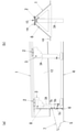
図1(a),(b)に示される第1実施例の軒先構造は、折板屋根における折板屋根板1の内部に位置される支持部材2,2が流れ方向に複数設けられ、それぞれの支持部材2には少なくとも垂下する縦部材3Aを備える軒先納め材3が固定され、これらの軒先納め材3には、下方から被覆するように化粧材4が取り付けられていると共に、軒先側に隣り合う軒先納め材3には、流れ方向に直交するように軒樋5が架設状に取り付けられている構成である。
In the eaves structure of the first embodiment shown in FIGS. 1A and 1B, a plurality of
この第1実施例の折板屋根板1は、図1(b)に示されるように左右方向に複数の山部10A及び谷部10Bを備え、その一つの山部10Aを図1(b)に示しているが、ハゼ締め式で接続される構造が示され、その内部には、図1(a)に示されるように流れ方向(=同図の左右方向)に複数の支持部材2,2が取り付けられている。
この折板屋根板1は、図2(d)に示されるように平板部11の両端が傾斜状に立ち上げられ(傾斜状の立ち上げ部12が設けられ)、該立ち上げ部12の上端に折返し状に上方へ延在させた折返し部13が形成され、更にその折返し部13の上端を略水平状に折り返した支持面部14が設けられ、該支持面部14の端縁を上方へ延在させてその先端を隣り合う折板屋根板1とハゼ締め(ハゼ部15)にて接続する構成であり、図示しないタイトフレームに固定される保持部材にて強固に且つ安定に取り付けられている。このタイトフレームは、下端が躯体に固定され、保持部材としては、正面から見て前記支持部材2のように見える(同一物品でもよい)ものが用いられる。
As shown in FIG. 1 (b), the folded
As shown in FIG. 2 (d), both ends of the
前記支持部材2は、図1(a)に示されるように前記折板屋根板1の山部10Aの内部に複数設けられる部材であって、前記折板屋根板1の立ち上げ部12と折返し部13間に形成されるく字状部16a、折返し部13と支持面部14間に形成されるく字状部16bに、それぞれ弾性嵌合される下側凹状部21、上側凸状部22をそれぞれ左右に備えている。
そのため、前記支持部材2は、左右に隣り合う前記折板屋根板1,1の立ち上げ部12と折返し部13間に形成されるく字状部16a、折返し部13と支持面部14間に形成されるく字状部16bが、それぞれ下側凹状部21及び上側凸状部22を弾性状に保持するため、左右に隣り合う前記折板屋根板1,1に、安定に支持されるものである。
なお、この支持部材2は、折板屋根板1の山部10Aの内部に配置可能であって、その組み付け後に容易に外れない形状であればよく、折板屋根板1に対して嵌合状に配置させるものであっても、折板屋根板1の先端(軒先端)からの嵌入、挿嵌状に配置させるものであってもよい。
As shown in FIG. 1A, the
Therefore, the
The
前記軒先納め材3は、図2(e)に示されるように下方へ延在する縦棒状の縦部材3Aを含んでおり、基端に扇状部分31を含んで流れ方向に延在する横部材3Bが組み合わされ、角度調整可能に取り付けられている。
前記縦部材3Aは、上端に前記横部材3B(扇状部分31)と重合する扇状部分32を備えて上下方向に延在する部材(L字材)であって、その横部分34も縦部分35も縦長の略矩形状であり、前記横部材3Bは、縦部分が流れ方向に延在する前記扇状部分31であって横部分がそこから略水平状に延在する固定面33であるL字材である。
なお、これらの「L字状材」は、正面から見える横部分と側面から見える縦部分とからなるL鋼等の素材からなることを意味し、前記扇状部分32,31は、それぞれの縦部分に形成されている。
それぞれの扇状部分31,32を接面状に重合させ、少なくとも一箇所に固定具を打ち込むことにより、横部材3Bと縦部材3Aとの傾斜角度を調整することができる。即ちこれらの構成は、前記角度調整機構の一態様である。この態様では、扇の要になる位置を、第1の固定部36とし、該固定部を軸として回動でき、周囲に相当する位置を第2の固定部37a、37bとしたので、適宜に回動させて固定具を打ち込んで容易に角度調整することができる。
As shown in FIG. 2 (e), the
The
It should be noted that these "L-shaped materials" mean that they are made of a material such as L steel consisting of a horizontal portion that can be seen from the front and a vertical portion that can be seen from the side surface, and the fan-shaped
The inclination angle between the
この第1実施例における前記折板屋根は、水平方向に延在する躯体上にタイトフレームが固定され、該タイトフレームに保持部材が固定され、該保持部材に折板屋根板1が保持される嵌合式構造であって、隣り合う折板屋根板1,1は、ハゼ締め式で取り付けられている。
なお、前記折板屋根板1は、面板部11(谷部10B)の両側縁12,12を表面側に立ち上げた折板屋根を構築する部材であって、立ち上がり部12の高さの中程には保持部材に弾性的に係合されるく字状の係合部16a,16bが形成され、左右に隣り合う折板屋根板1,1の上端はハゼ締めにて接続されている。
このような折板屋根においては、山部10Aは立ち上がり部12,12から上方部分が相当し、谷部10Bは面板部11が相当し、雨水等は谷部10Bである面板部11を流れ方向に流下する。
In the folded plate roof in the first embodiment, a tight frame is fixed on a frame extending in the horizontal direction, a holding member is fixed to the tight frame, and the folded
The folded
In such a folded plate roof, the
前記軒先納め材3のうち、軒先側に配置された軒先側の軒先納め材3の縦部材3Aに固定される樋受け材6は、図2(c)に示されるように軒樋5の側面部53から前記縦部材3Aへの固定部61と、軒樋5の建築物側の側面部53の下端531を受支する受支部62と、を備えている。この樋受け部材6は、軒樋5の建築物側の側面部53の下端531を支持する受支部62の他に、高さの中程に、側方へ垂れ下がる膨出部64を設けることで、下方が開放する溝状63が形成され、軒樋5の建築物側の側面部53の上端532を下方から差し込むように取り付けることができる。
Of the
前記樋受け材6に支持される軒樋5は、図2(b)に示されるように前記樋受け材6に受支されて内部にU字状の雨水等の排水路が設けられる部材であって、内部に導かれた雨水等は排水路から底面部51を流下される。
この軒樋5は、長さ方向に延在して略平坦状の底面部51の側端が立ち上げられ、軒先側(図面では左側)に、三つの傾斜面と二つの略水平面とで構成される側面部52が設けられ、建築物側(図面では右側)には、略垂直状に起立する側面部53が設けられ、これらの底面部51及び側面部52,53にて排水路が形成されている。
前記軒先側の側面部52の上端に位置する傾斜面と略水平面は、カバー材7の係合部72に保持(係合)される軒先端521である。また、前記側面53の下端には、隅部状の被保持部531が設けられ、前記樋受け材6の横片状の受支部62に、上方から載置状に配置されて支持される部位である。さらに、この側面部53の上端には、差込状の被取付部532が、前記樋受け材6の溝状の取付部63に、下方から挿入状に差し込まれて取り付けられる部位である。なお、この軒樋5は、前記軒先納め材3(縦部材3A)にビス5bにて固定されるが、前記樋受け材6と共に配されてビス5cにても固定されている。
The
This
The inclined surface and the substantially horizontal plane located at the upper end of the
前記軒樋5の開放上面にはカバー材7が配設されているが、このカバー材7は、図2(a)に示されるようにその下端(軒先端)72が前記軒樋5の軒先端521と係合され、その上端73が前記軒先納め材3(縦部材3A)に連絡されている。
このカバー材7は、前記軒樋5の内部に降雪が堆積したり、落ち葉等が侵入、堆積したり、鳥類等が巣作りすることを防止する部材であって、その表面(化粧面71)には雨水を内部へ導く導水口711として複数のスリット孔が形成され、その下端には略コ字状に形成された下端(係合部)72が、前記軒樋5の軒先端521と係合して取り付けられ、その上端付近に固定部73が形成され、該固定部73が、前記縦部材3Aに固定されている。
前記係合部72は、化粧面71の軒先端から斜め上方へ延在し、その先端を下方へ折曲し、更にその下端を内側へ折曲した略コ字状に形成され、化粧面71と係合部72との境界には下方へ凹む排水溝712が形成され、所定間隔で導水口が形成されている。
前記固定部73は、化粧面71の建築物側端付近に位置する部位であって、前記軒先納め材3(縦部材3A)にビス7bにて固定されている。
A
The
The engaging
The fixing
前記軒先納め材3の縦部材3Aの下端に取り付けられる化粧材4は、下方から被覆する役割を果たす軒天井材であり、図2(g)に示されるように縦部材3Aの下端に取り付けられた金具4A,4B、流れ方向に連続する補強金具4Cを介して固定されており、この化粧材4の荷重等は、それぞれの縦部材3Aから前記支持部材2に負担(分担)される。
The
なお、この第1実施例の軒先構造には、図2(f)に示される面材8が取り付けられ、該面材8が折板屋根の山部10Aの内部を軒先側から隠すと共に、軒先からの吹き上げ風の侵入を防ぐ役割も果たしている。この面材8は、前記軒先納め材3の縦部材3Aに固定される取付部材8Aの軒先側に固定されており、該取付部材8Aはて正面視が三角枠状に形成されている。
The
この第1実施例の軒先構造を既設の折板屋根に固定するには、予め軒先納め材3を取り付けた支持部材2を、流れ方向に複数固定する。
続いて、取り付けた軒先納め材3の縦部材3Aが鉛直状になるように微調整して臨ませ(固定し)、それぞれの縦部材3Aに金具4A~4Cを固定すると共にそれらに化粧材4を取り付ける。
また、軒先側に配置された軒先納め材3の縦部材3Aに、樋受け部材6や軒樋5、及びカバー材7を取り付ければよい。その際、軒樋5及びカバー材7は、流れ方向に直交するように取り付けるが、所定間隔で取り付ける樋受け材6は、隣り合う縦部材3Aにそれぞれビス5b,5cにて固定して取り付ける。
In order to fix the eaves structure of the first embodiment to the existing folded plate roof, a plurality of
Next, finely adjust (fix) the
Further, the
このように施工された第1実施例の軒先構造は、新築、既設を問わず各種の折板屋根に容易に適用され、安定に各種の軒樋5及び軒天井材等の化粧材4を取り付けることができる。
The eaves structure of the first embodiment constructed in this way is easily applied to various folded-plate roofs regardless of whether they are newly built or existing, and
さらに、この第1実施例では、軒先納め材3が、角度調整可能に取り付けられているので、任意の傾斜角度で安定に配設される、即ち任意の傾斜勾配の屋根構造に安定に軒樋5を取り付けることができる。
Further, in this first embodiment, since the
また、この第1実施例では、軒樋5の軒先側の側面上端521が、この軒樋5の上面を覆うカバー材7の下端(係合部72)と係合され、該カバー材7の上端(固定部73)が縦部材3Aに連絡されているので、軒樋4の軒先端521を折板屋根側へ引っ張るように保持するため、このカバー材7は軒樋5の荷重を保持するアームの作用をも果たす。
Further, in the first embodiment, the
このように本発明の軒先構造では、軒天井材等の各種の化粧材4は、多数の軒先納め材3の縦部材3Aに支持され、各種の軒樋5は、軒先側に取り付けられた複数の縦部材3Aに架設状に取り付けられているため、それぞれ様々な仕様の化粧材4や軒樋5を適宜に用いることができる。
特に前記第1実施例では、カバー材7が軒樋5の荷重を保持するアームの作用を果たすので、例えば多量の降雪がカバー材7の上面に堆積したり、軒樋5の内部に多量の雨水が流れることがあっても、該荷重によって軒樋5が変形したり或いは下方へ傾倒したり落下することを防止できる。
As described above, in the eaves structure of the present invention, various
In particular, in the first embodiment, since the
1 折板屋根板
10A 山部
10B 谷部
2 支持部材
21 下側凹状部
22 上側凸状部
3 軒先納め材
3A 縦部材
3B 横部材
4 化粧材
4A L字金具
4B 金具
4C 補強金具
5 軒樋
51 底面部
52 (軒先側の)側面部
521 軒先端
53 (建築物側の)側面部
531 被支持部
532 側面上端(被取付部)
6 樋受け材
62 支持部
63 取付部
7 カバー材
71 化粧面
711 導水口
712 排水溝
72 係合部
73 固定部
8 面材
8A 取付部材
1 Folded
6
Claims (3)
Priority Applications (1)
| Application Number | Priority Date | Filing Date | Title |
|---|---|---|---|
| JP2020143310A JP7515867B2 (en) | 2020-08-27 | 2020-08-27 | Eaves structure |
Applications Claiming Priority (1)
| Application Number | Priority Date | Filing Date | Title |
|---|---|---|---|
| JP2020143310A JP7515867B2 (en) | 2020-08-27 | 2020-08-27 | Eaves structure |
Publications (2)
| Publication Number | Publication Date |
|---|---|
| JP2022038691A true JP2022038691A (en) | 2022-03-10 |
| JP7515867B2 JP7515867B2 (en) | 2024-07-16 |
Family
ID=80498028
Family Applications (1)
| Application Number | Title | Priority Date | Filing Date |
|---|---|---|---|
| JP2020143310A Active JP7515867B2 (en) | 2020-08-27 | 2020-08-27 | Eaves structure |
Country Status (1)
| Country | Link |
|---|---|
| JP (1) | JP7515867B2 (en) |
Citations (7)
| Publication number | Priority date | Publication date | Assignee | Title |
|---|---|---|---|---|
| JPH0333121U (en) * | 1989-08-10 | 1991-04-02 | ||
| JPH0455552A (en) * | 1990-06-22 | 1992-02-24 | Gantan Beauty Kogyo Kk | Exterior edge storage device for folded roof structure |
| JPH04108948A (en) * | 1990-08-29 | 1992-04-09 | Gantan Beauty Kogyo Kk | open building structure |
| JPH05280160A (en) * | 1992-03-31 | 1993-10-26 | Gantan Beauty Kogyo Kk | Origami roof and its construction method |
| JPH06200589A (en) * | 1993-01-06 | 1994-07-19 | Sanko Metal Ind Co Ltd | Eaves ceiling |
| JPH09170312A (en) * | 1995-12-20 | 1997-06-30 | Sekisui Chem Co Ltd | Raindrop prevention structure on the roof eaves |
| JP2019007253A (en) * | 2017-06-27 | 2019-01-17 | 元旦ビューティ工業株式会社 | Eaves arabesque and eaves structure using the same |
-
2020
- 2020-08-27 JP JP2020143310A patent/JP7515867B2/en active Active
Patent Citations (7)
| Publication number | Priority date | Publication date | Assignee | Title |
|---|---|---|---|---|
| JPH0333121U (en) * | 1989-08-10 | 1991-04-02 | ||
| JPH0455552A (en) * | 1990-06-22 | 1992-02-24 | Gantan Beauty Kogyo Kk | Exterior edge storage device for folded roof structure |
| JPH04108948A (en) * | 1990-08-29 | 1992-04-09 | Gantan Beauty Kogyo Kk | open building structure |
| JPH05280160A (en) * | 1992-03-31 | 1993-10-26 | Gantan Beauty Kogyo Kk | Origami roof and its construction method |
| JPH06200589A (en) * | 1993-01-06 | 1994-07-19 | Sanko Metal Ind Co Ltd | Eaves ceiling |
| JPH09170312A (en) * | 1995-12-20 | 1997-06-30 | Sekisui Chem Co Ltd | Raindrop prevention structure on the roof eaves |
| JP2019007253A (en) * | 2017-06-27 | 2019-01-17 | 元旦ビューティ工業株式会社 | Eaves arabesque and eaves structure using the same |
Also Published As
| Publication number | Publication date |
|---|---|
| JP7515867B2 (en) | 2024-07-16 |
Similar Documents
| Publication | Publication Date | Title |
|---|---|---|
| US9765523B2 (en) | Rain gutter system | |
| US20090019789A1 (en) | Curb-mounted screen for rooftop equipment | |
| JP5948519B1 (en) | Drainage structure of gantry in installation structure of thin plate-like roof member | |
| US8870139B1 (en) | Strap mount for solar panels | |
| JP5977396B2 (en) | Sheet metal for roof | |
| JP7515867B2 (en) | Eaves structure | |
| EP2639379A1 (en) | System for the fixation of a roof rail | |
| JP5648995B2 (en) | Mounting structure of support frame and exterior structure | |
| JP6498081B2 (en) | Roof wiring structure and building | |
| JP6764740B2 (en) | Drainage structure and building at the eaves | |
| JP6047078B2 (en) | Fixing tool for roof installation and fixing structure for roof installation | |
| JP2005180090A (en) | Eaves structure with ventilation function | |
| US20040211125A1 (en) | Assembly clip for a rain gutter deflector | |
| JP4928225B2 (en) | Waterproof structure on the roof | |
| JP7721161B2 (en) | Eaves fittings and eaves structure | |
| JP7807928B2 (en) | Construction structure of rain gutter ventilation members | |
| JPH10273953A (en) | Installation structure of snow stopper | |
| JP2021063410A (en) | Shoot port cover of downpipe | |
| JP6192453B2 (en) | Roof structure, solar cell module fixture, solar cell module mounting structure, and solar cell module mounting method | |
| JP7161324B2 (en) | Mounting structure | |
| JP2005180091A (en) | Flat roof eaves structure | |
| JP6678344B2 (en) | Solar power generator | |
| JP6773584B2 (en) | Support members and outdoor structures | |
| JP6980399B2 (en) | Structure around the eaves of the building | |
| JP2003082823A (en) | Fixing method and fixing structure of solar collector |
Legal Events
| Date | Code | Title | Description |
|---|---|---|---|
| A621 | Written request for application examination |
Free format text: JAPANESE INTERMEDIATE CODE: A621 Effective date: 20230427 |
|
| A131 | Notification of reasons for refusal |
Free format text: JAPANESE INTERMEDIATE CODE: A131 Effective date: 20240123 |
|
| A977 | Report on retrieval |
Free format text: JAPANESE INTERMEDIATE CODE: A971007 Effective date: 20240124 |
|
| A521 | Request for written amendment filed |
Free format text: JAPANESE INTERMEDIATE CODE: A523 Effective date: 20240319 |
|
| TRDD | Decision of grant or rejection written | ||
| A01 | Written decision to grant a patent or to grant a registration (utility model) |
Free format text: JAPANESE INTERMEDIATE CODE: A01 Effective date: 20240604 |
|
| A61 | First payment of annual fees (during grant procedure) |
Free format text: JAPANESE INTERMEDIATE CODE: A61 Effective date: 20240626 |
|
| R150 | Certificate of patent or registration of utility model |
Ref document number: 7515867 Country of ref document: JP Free format text: JAPANESE INTERMEDIATE CODE: R150 |