JP2021186998A - Method for producing precast concrete member, and precast concrete member - Google Patents
Method for producing precast concrete member, and precast concrete member Download PDFInfo
- Publication number
- JP2021186998A JP2021186998A JP2020091956A JP2020091956A JP2021186998A JP 2021186998 A JP2021186998 A JP 2021186998A JP 2020091956 A JP2020091956 A JP 2020091956A JP 2020091956 A JP2020091956 A JP 2020091956A JP 2021186998 A JP2021186998 A JP 2021186998A
- Authority
- JP
- Japan
- Prior art keywords
- concrete
- reinforcing bar
- precast concrete
- bottom plate
- precast
- Prior art date
- Legal status (The legal status is an assumption and is not a legal conclusion. Google has not performed a legal analysis and makes no representation as to the accuracy of the status listed.)
- Granted
Links
Images



Landscapes
- Rod-Shaped Construction Members (AREA)
- Manufacturing Of Tubular Articles Or Embedded Moulded Articles (AREA)
Abstract
Description
本発明は、プレキャストコンクリート部材の製造方法およびプレキャストコンクリート部材に関する。 The present invention relates to a method for manufacturing a precast concrete member and a precast concrete member.
コンクリート構造物の施工にあたり、プレキャスト工法を採用することで、工期短縮化を図る場合がある。プレキャスト工法は、所定の位置にプレキャスト部材を配設して固定するのみで施工が完了するため、現場での型枠の設置、コンクリート打設および養生、型枠の脱型を要する場所打ち工法に比べて、現場での作業が容易である。また、断面の一部をプレキャスト化するハーフプレキャスト工法では、現場でのコンクリート打設量の低減化に加え、型枠や支保部材等の省略あるいは低減化を図ることが可能となる。
プレキャスト部材は、工場や製造ヤード等において、型枠内にコンクリートを打設することにより形成するのが一般的である。そのため、型枠の組み立て、コンクリートの締固め、型枠の脱型などに手間がかかっていた。一般的なプレキャスト部材の製造方法とは異なるものとして、所定の強度を早期に発現する吹付けコンクリートによりコンクリート部材を形成する場合がある。例えば、特許文献1には、成形型面に対してコンクリートを所定の厚さで吹き付けることで成形体を形成するコンクリート製品の製造方法が開示されている。
ところが、特許文献1のコンクリート製品の製造方法は、吹付け工法により管体を立てた状態で製造するものであり、筒状部材の外周面全周にわたってコンクリートを吹き付けるため、横置きした状態で製作するという思想はない。さらに、工場などにおいて遠心成形装置を用いてコンクリート製品を製造する方法も開示されているが、特殊な装置が必要なために建設現場内での製作には採用されない。
また、特許文献2には、補強材の外側に結束した格子状の繋材(網材)に対して下方から吹付けコンクリートを所定の厚さで吹付けることで、U字状断面の梁を構築する躯体構築方法が開示されている。
ところが、特許文献2の躯体構築方法は、躯体そのものを吹き付けで構築するものであり、プレキャスト部材の構築方法を示したものではない。また、梁やスラブは現場での打設後に、たわみが生じないよう、所定の強度が発現するまで支保工で支持した状態を保つ必要がある。特許文献2の躯体構築方法でも、梁、スラブが吹付後にたわまないように、事前に支保工を設ける必要があるため、支保工設置の手間が生じる上に、支保工設置箇所への吹付ができない。
When constructing concrete structures, the precast method may be used to shorten the construction period. The precast method is a cast-in-place method that requires on-site formwork installation, concrete placement and curing, and formwork demolding because the construction is completed simply by arranging and fixing the precast members in place. In comparison, it is easier to work in the field. Further, in the half precast method in which a part of the cross section is precast, in addition to reducing the amount of concrete placed at the site, it is possible to omit or reduce the formwork, support member and the like.
Precast members are generally formed by placing concrete in a formwork in a factory, a manufacturing yard, or the like. Therefore, it took time and effort to assemble the formwork, compact the concrete, and remove the formwork. As a method different from the general method for manufacturing a precast member, a concrete member may be formed by sprayed concrete that develops a predetermined strength at an early stage. For example,
However, the method for manufacturing a concrete product in
Further, in
However, the skeleton construction method of
本発明は、吹付けコンクリートにより断面に空洞を有するプレキャストコンクリート部材を建設現場内で横置きの状態で製造することを可能としたプレキャストコンクリート部材の製造方法を提案することを課題とし、さらには、従来工法に比べて短期かつ安価に製造可能なプレキャストコンクリート部材を提案することを課題とする。 An object of the present invention is to propose a method for manufacturing a precast concrete member, which enables a precast concrete member having a cavity in a cross section to be manufactured horizontally in a construction site by spraying concrete, and further. The challenge is to propose precast concrete members that can be manufactured in a short period of time and at low cost compared to the conventional construction method.
前記課題を解決するための本発明のプレキャストコンクリート部材の製造方法は、断面中心部に空洞を有するプレキャストコンクリート部材を建設現場で製造するものであって、主筋とせん断補強筋で構成される鉄筋かごを底板の上面に載置する載置工程と、前記鉄筋かごの内側に納まるように配設された仕切材に対して前記鉄筋かごの外側からコンクリートを吹き付け、前記底板側の面が解放された開断面のコンクリート層を形成する吹付工程と、前記コンクリート層の表面を均す均し工程とを備えている。前記載置工程では、前記主筋が前記底板の板面と平行になるように前記鉄筋かごを横置きし、前記仕切材は、断面略U字形状(例えば、U字状、V字状、コ字状、C字状等)で、前記底板側が開口するように(略n字状になるように)配設する。なお、「底板」は、プレキャストコンクリート部材を製造する箇所に設けられた板材である。
かかるプレキャストコンクリート部材の製造方法によれば、コンクリートを吹き付けることによりプレキャストコンクリート部材を形成するため、大掛かりな型枠等を要することなく、断面中心部に空洞を有するプレキャストコンクリート部材を建設現場内で簡易かつ早期に製造することができる。また、主筋を横にした状態で横置きで製造するため、柱や梁などの長尺な部材を製造する場合であっても、大掛かりな足場や支保部材などを必要としない。すなわち、本発明のプレキャストコンクリート部材の製造方法によれば、型枠、足場、支保部材等の設置や撤去に要する手間や費用を省略あるいは削減することが可能となり、従来工法に比べて短期かつ安価にプレキャストコンクリート部材を製造することができる。
The method for manufacturing a precast concrete member of the present invention for solving the above problems is to manufacture a precast concrete member having a cavity in the center of a cross section at a construction site, and is a reinforcing bar cage composed of a main bar and a shear reinforcing bar. Was placed on the upper surface of the bottom plate, and concrete was sprayed from the outside of the reinforcing bar cage onto the partition material arranged so as to fit inside the reinforcing bar cage, and the surface on the bottom plate side was released. It includes a spraying step of forming a concrete layer having an open cross section and a leveling step of leveling the surface of the concrete layer. In the pre-described step, the reinforcing bar cage is placed horizontally so that the main bar is parallel to the plate surface of the bottom plate, and the partition material has a substantially U-shaped cross section (for example, U-shaped, V-shaped, U-shaped, U-shaped, U-shaped, U-shaped, U-shaped, U-shaped, U-shaped, U-shaped, U-shaped, U-shaped, U-shaped, U-shaped, U-shaped, U-shaped, U-shaped, U-shaped, U-shaped, U-shaped, U-shaped, Arrange in a character shape, a C shape, etc.) so that the bottom plate side is open (so as to be substantially n-shaped). The "bottom plate" is a plate material provided at a place where a precast concrete member is manufactured.
According to the method for manufacturing a precast concrete member, since the precast concrete member is formed by spraying concrete, a precast concrete member having a cavity in the center of a cross section can be easily manufactured in a construction site without requiring a large formwork or the like. Moreover, it can be manufactured at an early stage. Further, since the main bar is laid horizontally and manufactured horizontally, even when a long member such as a column or a beam is manufactured, a large-scale scaffolding or a support member is not required. That is, according to the method for manufacturing a precast concrete member of the present invention, it is possible to omit or reduce the labor and cost required for installing and removing formwork, scaffolding, support members, etc., which is shorter and cheaper than the conventional method. Precast concrete members can be manufactured.
前記吹付工程では、前記鉄筋かごの下方に前記主筋と平行な一対のストッパを配設した状態でコンクリートを吹き付けるのが望ましい。こうすることで、開断面のコンクリート層を形成できる。また、前記均し工程では、前記コンクリート層の仕上面と平行に設置されたガイドに沿ってスクレーパを移動させることで、前記コンクリート層の表面を均すのが望ましい。こうすることで、コンクリート層の表面を容易に平滑にすることができる。
また、前記プレキャストコンクリート部材の製造方法は、前記仕切材の内側の空間に挿入したノズルから下方に向けてコンクリートを吹き付ける第二吹付工程をさらに備えていてもよい。前記第二吹付工程では、前記ストッパを撤去した状態でコンクリートを吹き付けることで前記吹付工程において形成した開断面のコンクリート層を閉合し、閉断面にする。こうすることで、主筋を横に倒した状態で筒状部材を製造することが可能となる。主筋を立設した状態で筒状部材を製造する場合には、足場や支保部材の設置作業が必要となるが、主筋を横に倒した状態で筒状部材を製造すると、足場や支保部材を低減あるいは省略することができるため、簡易かつ安価にプレキャストコンクリート部材を製造することができる。
In the spraying step, it is desirable to spray concrete in a state where a pair of stoppers parallel to the main bar are arranged below the reinforcing bar cage. By doing so, a concrete layer having an open cross section can be formed. Further, in the leveling step, it is desirable to level the surface of the concrete layer by moving the scraper along a guide installed in parallel with the finished surface of the concrete layer. By doing so, the surface of the concrete layer can be easily smoothed.
Further, the method for manufacturing the precast concrete member may further include a second spraying step of spraying concrete downward from a nozzle inserted into the space inside the partition material. In the second spraying step, concrete is sprayed with the stopper removed to close the concrete layer having an open cross section formed in the spraying step to form a closed cross section. By doing so, it becomes possible to manufacture a tubular member with the main bar tilted sideways. When manufacturing a tubular member with the main bar upright, it is necessary to install scaffolding and support members, but when manufacturing a tubular member with the main bar laid down sideways, the scaffolding and support member can be manufactured. Since it can be reduced or omitted, the precast concrete member can be manufactured easily and inexpensively.
本発明のプレキャストコンクリート部材は、断面中心部に空洞部を有するものであって、前記空洞部を形成するための仕切材が内部に残置されており、底板の上に載置された鉄筋かごの外側から、前記仕切材に対して吹付けられたコンクリートからなるコンクリート層が形成されている。かかるプレキャストコンクリート部材によれば、仕切材に向けて吹付けコンクリートを吹き付けることで簡易に製造することができる。また、金網からなる仕切材が設けられているため、内部にコンクリートを打設した際に接合面における接合性が向上する。 The precast concrete member of the present invention has a cavity in the center of the cross section, and a partition material for forming the cavity is left inside, and the reinforcing bar cage placed on the bottom plate has a cavity. From the outside, a concrete layer made of concrete sprayed on the partition material is formed. According to such a precast concrete member, it can be easily manufactured by spraying sprayed concrete toward a partition material. Further, since the partition material made of wire mesh is provided, the bondability on the joint surface is improved when concrete is poured inside.
本発明のプレキャストコンクリート部材の製造方法によれば、吹付けコンクリートによりプレキャストコンクリート部材を建設現場内において横置きの状態で製造することが可能となる。また、本発明のプレキャストコンクリート部材は、従来工法に比べて短期かつ安価に製造できる。 According to the method for manufacturing a precast concrete member of the present invention, the precast concrete member can be manufactured horizontally in a construction site by spraying concrete. Further, the precast concrete member of the present invention can be manufactured in a short time and at low cost as compared with the conventional method.
<第一実施形態>
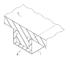
第一実施形態では、ハーフプレキャスト工法により梁Bを形成する場合において使用する、プレキャストコンクリート部材1の建設現場内において製造する製造方法について説明する。図1は、ハーフプレキャスト工法により形成した梁Bの斜視図である。
梁Bは、図1に示すように、中心部に空洞を有した断面U字状のプレキャストコンクリート部材1と、プレキャストコンクリート部材1の内部および上面に打設された現場打ちコンクリート2とにより形成されている。プレキャストコンクリート部材1は、いわゆるハーフプレキャスト部材である。
図2にプレキャストコンクリート部材1の製造方法のフローチャートを示す。図2に示すように、プレキャストコンクリート部材1の製造方法は、組立工程S1、載置工程S2、仕切工程S3、吹付工程S4および均し工程S5を備えている。
<First Embodiment>
In the first embodiment, a manufacturing method for manufacturing the
As shown in FIG. 1, the beam B is formed by a
FIG. 2 shows a flowchart of a method for manufacturing the
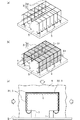
組立工程S1は、鉄筋かご3を組み立てる工程である。図3(a)に組立工程S1を示す。本実施形態の鉄筋かご3は、図3(a)に示すように、梁Bの軸方向に沿って配筋された主筋31と、主筋31と交差(直交)するあばら筋(せん断補強筋)32とを組み立てることにより形成されている。本実施形態のあばら筋32は、門型を呈している。あばら筋32の両端には、先端を内側に折り曲げることでJ字状のフックが形成されている。なお、あばら筋32の形状は、梁Bの断面形状に応じて適宜決定すればよい。また、あばら筋32の端部の形状も限定されるものではなく、例えば、鉤型であってもよい。
The assembly step S1 is a step of assembling the reinforcing
載置工程S2は、図3(a)に示すように、鉄筋かご3を、底板Sの上面に載置する工程である。鉄筋かご3は、あばら筋32の端部が下側になるように、スペーサー5を介して底板S上に載置する。鉄筋かご3は、主筋31が底板Sの板面と平行になるように載置する。載置工程S2では、かぶり厚管理用スペーサー51を鉄筋かご3の側面および上面に取り付ける。かぶり厚管理用スペーサー51は、鉄筋かご3に必要なかぶり厚さと同等の高さを有している。ここで、本明細書における「底板S」は、プレキャストコンクリート部材1を製造する場所に設置された平板である。
The mounting step S2 is a step of mounting the reinforcing
図3(b)に仕切工程S3を示す。仕切工程S3は、図3(b)に示すように、鉄筋かご3の内面に沿って仕切材4を配設する工程である。本実施形態の仕切材4は、波板からなる。仕切材4は、略U字形状を呈していて、底板S側が開口するようにn字状に配設する。仕切材4は、鉄筋かご3に脱着可能に取り付ける。仕切材4の鉄筋かご3への取付構造は限定されるものではなく、例えば、ボルトを介して固定してもよいし、フック状の係止部材に係止させてもよい。仕切材4の表面(コンクリートに接する面)に、剥離剤(離型剤)を塗布してもよい。
FIG. 3B shows the partition step S3. As shown in FIG. 3B, the partition step S3 is a step of arranging the
図3(c)に吹付工程S4を示す。吹付工程S4は、図3(c)に示すように、コンクリート層6を形成する工程である。コンクリート層6は、仕切材4に対して鉄筋かご3の外側からコンクリートを吹き付けることにより形成する。コンクリートは、鉄筋かご3が所定のかぶり厚を確保できるように、かぶり厚管理用スペーサー51(図3(b)参照)が埋まるまで吹き付ける。また、コンクリートは、鉄筋かご3の両端の下側に対しても吹き付けるものとする。すなわち、底板Sと鉄筋かご3との間の隙間に対してもコンクリートを吹き付ける。なお、鉄筋かご3の両端の下側にコンクリートを吹き付ける前に、鉄筋かご3の下方に主筋31と平行な一対のストッパ7,7を間隔をあけて配設しておく(図3(c)参照)。ストッパ7には、例えば、鉄筋かご3の長さ(主筋31の長さ)以上の長さを有し、スペーサー5(必要かぶり厚さ)以上の高さを有した角柱状の木材(例えば、桟木)を使用すればよい。本実施形態では、ストッパ7を鉄筋かご3の両端よりも内側に配設する。鉄筋かご3の下側にコンクリートを吹き付ける際には、鉄筋かご3の外側からストッパ7に向けて吹付ける。ストッパ7により、鉄筋かご3の下部にコンクリートが入り込むことが防止され、コンクリート層6は下面が開口した(底板S側が解放された)開断面となる。なお、ストッパ7を配設するタイミングはコンクリートの吹付け前であれば限定されるものではなく、例えば、載置工程S2や仕切工程S3においてストッパ7を配設してもよい。
FIG. 3C shows the spraying step S4. The spraying step S4 is a step of forming the
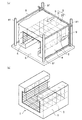
図4(a)に均し工程S5を示す。均し工程S5は、図4(a)に示すように、コンクリート層6の表面を均す(平らにする)工程である。均し工程S5では、まず、コンクリートが吹き付けられた鉄筋かご3の周囲にガイド8を設置する。ガイド8は、主筋31(コンクリート層6の仕上げ面)と平行に設置する。本実施形態では、コンクリートが吹き付けられた鉄筋かご3の角部および下端に沿ってガイド8を配設する。すなわち、上下2段のガイド8を鉄筋かご3の左右に配設する。ガイド8は、底板Sあるいは底板Sが設置された作業面(例えば、床面)に立設された支柱81により支持する。ガイド8は、鉄筋かご3から所定の間隔を確保して配設する。本実施形態では、鉄筋かご3とガイド8との間隔を、かぶり厚とスクレーパ9の厚さとの合計値とする。すなわち、ガイド8は、コンクリート層6の仕上げ面からスクレーパ9の厚さ分の間隔をあけた位置に配設する。ガイド8を所定の位置に設置したら、ガイド8に沿ってスクレーパ9を移動させて、余分なコンクリートを削り取ることで、コンクリート層6の表面を均す。スクレーパ9は、コンクリートが吹き付けられた鉄筋かご3(プレキャストコンクリート部材1)の上面及び側面に沿って移動させる。
FIG. 4A shows the leveling step S5. The leveling step S5 is a step of leveling (flattening) the surface of the
コンクリート層6の表面を均し、コンクリートを養生したら、仕切材4を取り外すことで、断面U字状のプレキャストコンクリート部材1が完成する。図4(b)にプレキャストコンクリート部材1を示す。本実施形態のプレキャストコンクリート部材1は、図4(b)に示すように、内面に波形の凹凸が形成されているため、現場打ちコンクリート2との接合性が高い。
また、本実施形態のプレキャストコンクリート部材1の製造方法によれば、ガイド8に沿ってスクレーパ9を移動させることで、コンクリートの表面を容易に平滑にすることができる。
また、プレキャストコンクリート部材1は、コンクリートを吹き付けることにより形成するため、大掛かりな型枠等を要することなく、簡易かつ早期に製造することができる。型枠として、コア部の仕切材4を配設するのみのため、型枠の設置や脱型の手間を低減できる。
また、主筋31を横にした状態で製造するため、大掛かりな足場や支保部材などを必要とせず、型枠、足場、支保部材等の設置や撤去に要する手間や費用を省略あるいは削減することが可能となる。
また、吹付け機以外に特殊な装置を必要としないため、比較的小さいスペースでプレキャストコンクリート部材1を製造することが可能となり、ひいては、現場の敷地内での実施も可能である。
After the surface of the
Further, according to the method for manufacturing the precast
Further, since the precast
In addition, since it is manufactured with the
Further, since no special device other than the spraying machine is required, the precast
<第二実施形態>
第二実施形態では、ハーフプレキャスト工法により柱Pを形成する場合において使用する、プレキャストコンクリート部材1の製造方法について説明する。図5は、ハーフプレキャスト工法により形成した柱Pの斜視図である。柱Pは、図5に示すように、中心部に空洞を有した角筒状のプレキャストコンクリート部材1と、プレキャストコンクリート部材1の内部に打設された現場打ちコンクリート2とにより形成されている。
図6に第二実施形態のプレキャストコンクリート部材1の製造方法のフローチャートを示す。図6に示すように、プレキャストコンクリート部材1の製造方法は、組立工程S1、載置工程S2、仕切工程S3、第一吹付工程S4、均し工程S5および第二吹付工程S6を備えている。
<Second embodiment>
In the second embodiment, a method for manufacturing the precast
FIG. 6 shows a flowchart of a method for manufacturing the precast
図7(a)に組立工程S1を示す。組立工程S1は、鉄筋かご3を組み立てる工程である。本実施形態の鉄筋かご3は、図7(a)に示すように、梁Bの軸方向に沿って配筋された主筋31と、主筋31と交差(直交)する帯筋(せん断補強筋)33とを組み立てることにより形成されている。本実施形態の鉄筋かご3は角筒状を呈していて、帯筋33は枠状に形成されている。なお、帯筋33の形状は限定されるものではなく、例えば円環状であってもよい。
FIG. 7A shows the assembly process S1. The assembly step S1 is a step of assembling the reinforcing
載置工程S2は、図7(a)に示すように、鉄筋かご3を、底板S上に載置する工程である。鉄筋かご3は、主筋31が底板Sの板面と平行になるように、スペーサー5を介して底板S上に載置する。また、載置工程S2では、かぶり厚管理用スペーサー51を鉄筋かご3の側面および上面に取り付ける。かぶり厚管理用スペーサー51は、鉄筋かご3に必要なかぶり厚さと同等の高さを有している。
The mounting step S2 is a step of mounting the reinforcing
図7(b)に仕切工程S3を示す。仕切工程S3は、図7(b)に示すように、鉄筋かご3の内面に沿って仕切材4を配設する工程である。本実施形態の仕切材4は、鉄筋かご3と同等の長さを有し、かつ、鉄筋かご3の四つの内側面のうちの三面の周長と同等の幅を有した金網からなる。仕切材4を構成する金網は、第一吹付工程S4において吹付けるコンクリート(吹付けコンクリート)の骨材よりも小さい網目を有するものが望ましい。仕切材4は、下面(底板S側)が開口するように(n字状になるように)、鉄筋かご3の四つの内側面のうちの下側の面以外の三面(上面および両側面)に固定する。
FIG. 7B shows the partition step S3. As shown in FIG. 7B, the partitioning step S3 is a step of arranging the
図7(c)に第一吹付工程S4を示す。吹付工程S4は、図7(c)に示すように、コンクリート層6を形成する工程である。コンクリート層6は、仕切材4に対して鉄筋かご3の外側からコンクリートを吹き付けることにより形成する。コンクリートは、鉄筋かご3が所定のかぶり厚を確保できるように、かぶり厚管理用スペーサー51が埋まるまで吹き付ける。また、コンクリートは、鉄筋かご3の下側に対しても吹き付けるものとする。すなわち、底板Sと鉄筋かご3との間の隙間に対してもコンクリートを吹き付ける。鉄筋かご3の下方には、主筋31と平行な一対のストッパ7,7を間隔をあけて配設しておき、鉄筋かご3の下側に吹き付けるコンクリートは、鉄筋かご3の外側からストッパ7に向けて吹付ける。こうすることで、仕切材4の外側に下面が開口した(開口部61が形成された)吹付コンクリートからなる開断面のコンクリート層6を形成する。なお、ストッパ7には、例えば、鉄筋かご3の長さ(主筋31の長さ)以上の長さを有し、スペーサー5(必要かぶり厚さ)以上の高さを有した角柱状の木材(例えば、桟木)を使用すればよい。また、ストッパ7を配設するタイミングは、コンクリートを吹き付ける前であれば限定されるものではなく、例えば、載置工程S2や仕切工程S3においてストッパ7を配設してもよい。
FIG. 7C shows the first spraying step S4. The spraying step S4 is a step of forming the
図8(a)に均し工程S5を示す。均し工程S5は、図8(a)に示すように、コンクリート層6の表面を均す工程である。均し工程S5では、まず、コンクリートが吹き付けられた鉄筋かご3の周囲にガイド8を設置する。ガイド8の詳細は、第一実施形態で示した内容と同様なため、詳細な説明は省略する。ガイド8を所定の位置に設置したら、ガイド8に沿ってスクレーパ9を移動させて余分なコンクリートを削り取ることで、コンクリート層6の表面を均す。スクレーパ9は、コンクリートが吹き付けられた鉄筋かご3(プレキャストコンクリート部材1)の上面及び側面に沿って移動させる。
FIG. 8A shows the leveling step S5. The leveling step S5 is a step of leveling the surface of the
図8(b)および(c)に第二吹付工程S6を示す。第二吹付工程S6では、第一吹付工程S4において形成した開断面のコンクリート層6を閉合し、閉断面のコンクリート層6を形成する。第二吹付工程S6は、表面を均したコンクリート層6の養生後、図8(b)に示すように、ストッパ7を撤去してから行う。ストッパ7の撤去後、図8(c)に示すように、仕切材4の内側の空間に挿入したノズルNから下方に向けてコンクリートを吹き付けることで、コンクリート層6の開口部61を第二の吹付けコンクリート62により閉合する。こうすることで、断面中心部に空洞部を有するプレキャストコンクリート部材1が製造される。プレキャストコンクリート部材1の内部(内面)には、仕切材4が残置されている。
8 (b) and 8 (c) show the second spraying step S6. In the second spraying step S6, the
本実施形態のプレキャストコンクリート部材1は、内面に金網(仕切材4)が設けられているため、現場打ちコンクリート2との接合性が高い。
また、本実施形態のプレキャストコンクリート部材1の製造方法によれば、金網からなる仕切材4を側型枠として使用し、撤去も要しないため、脱型の手間を省略できる。
この他の第二実施形態のプレキャストコンクリート部材1の製造方法の作用効果は、第一実施形態で示した内容と同様なため、詳細な説明は省略する。
Since the precast
Further, according to the method for manufacturing the precast
Since the operation and effect of the method for manufacturing the precast
以上、本発明に係る実施形態について説明したが、本発明は前述の実施形態に限られず、前記の各構成要素については本発明の趣旨を逸脱しない範囲で適宜変更が可能である。
例えば、前記第一実施形態では仕切材4として波板を使用し、前記第二実施形態では仕切材4として金網を使用したが、仕切材4を構成する材料は波板に限定されるものではなく、例えば、平板やシートであってもよい。
また、仕切材4を設置するタイミングは、鉄筋かご3を底板Sに載置する前であってもよいし、載置後であってもよい。すなわち、載置工程S2は、組立工程S1後に行ってもよいし、仕切工程S3後に行ってもよい。
また、前記実施形態では、仕切工程S3において、仕切材4を鉄筋かご3の内面に着脱可能に設ける、あるいは鉄筋かご3の内面に固定する場合について説明したが、仕切材4は鉄筋かご3の内側に収まるように配設されていればよく、必ずしも鉄筋かご3に取り付ける必要はない。例えば、鉄筋かご3の内側の空間に、略U字状の仕切材4を鉄筋かご3の内面から隙間をあけて設けてもよい。
また、前記実施形態では、鉄筋かご3を組み立ててから、スペーサー5上に載置するものとしたが、スペーサー5上において、鉄筋を組み立ててもよい。すなわち、組立工程S1と載置工程S2は同時に行ってもよい。
前記実施形態では、プレキャストコンクリート部材1の上面に対してもスクレーパ9を利用して表面を均すものとしたが、プレキャストコンクリート部材1の上面はコテ仕上を行ってもよい。
Although the embodiments according to the present invention have been described above, the present invention is not limited to the above-described embodiments, and each of the above-mentioned components can be appropriately changed without departing from the spirit of the present invention.
For example, in the first embodiment, a corrugated sheet is used as the
Further, the timing of installing the
Further, in the above-described embodiment, the case where the
Further, in the above embodiment, the reinforcing
In the above embodiment, the
1 プレキャストコンクリート部材
2 現場打ちコンクリート
3 鉄筋かご
31 主筋
32 あばら筋(せん断補強筋)
33 帯筋(せん断補強筋)
4 仕切材
5 スペーサー
6 コンクリート層
7 ストッパ
8 ガイド
9 スクレーパ
B 梁
N ノズル
P 柱
S 底板
S1 組立工程
S2 載置工程
S3 仕切工程
S4 吹付工程(第一吹付工程)
S5 均し工程
S6 第二吹付工程
1 Precast
33 band reinforcement (shear reinforcement)
4
S5 leveling process S6 second spraying process
Claims (4)
主筋とせん断補強筋で構成される鉄筋かごを底板の上面に載置する載置工程と、
前記鉄筋かごの内側に納まるように配設された仕切材に対して前記鉄筋かごの外側からコンクリートを吹き付け、前記底板側の面が解放された開断面のコンクリート層を形成する吹付工程と、
前記コンクリート層の表面を均す均し工程と、を備え、
前記載置工程では、前記主筋が前記底板の板面と平行になるように前記鉄筋かごを横置きし、
前記仕切材は、断面略U字形状で、前記底板側が開口するように配設することを特徴とする、プレキャストコンクリート部材の製造方法。 It is a manufacturing method of a precast concrete member that manufactures a precast concrete member having a cavity in the center of a cross section at a construction site.
A mounting process in which a reinforcing bar cage consisting of a main bar and a shear reinforcing bar is placed on the upper surface of the bottom plate,
A spraying step of spraying concrete from the outside of the reinforcing bar cage onto the partition material arranged so as to fit inside the reinforcing bar cage to form a concrete layer having an open cross section with the surface on the bottom plate side open.
The concrete layer is provided with a leveling step of leveling the surface of the concrete layer.
In the pre-described step, the reinforcing bar cage is placed horizontally so that the main bar is parallel to the plate surface of the bottom plate.
A method for manufacturing a precast concrete member, wherein the partition material has a substantially U-shaped cross section and is arranged so that the bottom plate side is open.
前記均し工程では、前記コンクリート層の仕上面と平行に設置されたガイドに沿ってスクレーパを移動させることで、前記コンクリート層の表面を均すことを特徴とする、請求項1に記載のプレキャストコンクリート部材の製造方法。 In the spraying step, concrete is sprayed in a state where a pair of stoppers parallel to the main bar are arranged below the reinforcing bar cage.
The precast according to claim 1, wherein in the leveling step, the surface of the concrete layer is leveled by moving the scraper along a guide installed in parallel with the finished surface of the concrete layer. Manufacturing method of concrete members.
前記第二吹付工程では、前記ストッパを撤去した状態でコンクリートを吹き付けることで、前記吹付工程において形成した開断面のコンクリート層を閉合し、閉断面にすることを特徴とする、請求項2に記載のプレキャストコンクリート部材の製造方法。 It is further equipped with a second spraying process in which concrete is sprayed downward from a nozzle inserted into the space inside the partition material.
2. The second aspect of the present invention is described in claim 2, wherein concrete is sprayed with the stopper removed to close the concrete layer having an open cross section formed in the spraying step to form a closed cross section. How to manufacture precast concrete members.
前記空洞部を形成するための仕切材が内部に残置されており、
底板の上に載置された鉄筋かごの外側から、前記仕切材に対して吹付けられたコンクリートからなるコンクリート層が形成されていることを特徴とする、プレキャストコンクリート部材。 A precast concrete member having a cavity in the center of the cross section.
A partition material for forming the cavity is left inside,
A precast concrete member, characterized in that a concrete layer made of concrete sprayed on the partition material is formed from the outside of a reinforcing bar cage placed on a bottom plate.
Priority Applications (1)
| Application Number | Priority Date | Filing Date | Title |
|---|---|---|---|
| JP2020091956A JP7281431B2 (en) | 2020-05-27 | 2020-05-27 | Precast concrete member manufacturing method and precast concrete member |
Applications Claiming Priority (1)
| Application Number | Priority Date | Filing Date | Title |
|---|---|---|---|
| JP2020091956A JP7281431B2 (en) | 2020-05-27 | 2020-05-27 | Precast concrete member manufacturing method and precast concrete member |
Publications (2)
| Publication Number | Publication Date |
|---|---|
| JP2021186998A true JP2021186998A (en) | 2021-12-13 |
| JP7281431B2 JP7281431B2 (en) | 2023-05-25 |
Family
ID=78850602
Family Applications (1)
| Application Number | Title | Priority Date | Filing Date |
|---|---|---|---|
| JP2020091956A Active JP7281431B2 (en) | 2020-05-27 | 2020-05-27 | Precast concrete member manufacturing method and precast concrete member |
Country Status (1)
| Country | Link |
|---|---|
| JP (1) | JP7281431B2 (en) |
Cited By (1)
| Publication number | Priority date | Publication date | Assignee | Title |
|---|---|---|---|---|
| CN118578492A (en) * | 2024-06-04 | 2024-09-03 | 中国建筑第二工程局有限公司 | A highly efficient construction method for prefabricated steel formwork building exterior beams |
Citations (6)
| Publication number | Priority date | Publication date | Assignee | Title |
|---|---|---|---|---|
| JPS6030244B2 (en) * | 1979-10-26 | 1985-07-15 | 靖郎 伊東 | Manufacturing method of concrete products |
| JPS6149049A (en) * | 1984-08-11 | 1986-03-10 | 清水建設株式会社 | PC parts such as beams |
| JPH04131443A (en) * | 1990-09-21 | 1992-05-06 | Okumura Corp | Reinforced concrete structures with beams and columns |
| JPH04166540A (en) * | 1990-10-29 | 1992-06-12 | Ohbayashi Corp | Beam form pc plate and manufacture thereof |
| JPH08184099A (en) * | 1995-10-09 | 1996-07-16 | Okumura Corp | Reinforced concrete structures of beams and columns |
| KR20080101218A (en) * | 2007-05-16 | 2008-11-21 | 한국건설기술연구원 | Concrete structure with fireproof board permanent formwork and construction method |
-
2020
- 2020-05-27 JP JP2020091956A patent/JP7281431B2/en active Active
Patent Citations (6)
| Publication number | Priority date | Publication date | Assignee | Title |
|---|---|---|---|---|
| JPS6030244B2 (en) * | 1979-10-26 | 1985-07-15 | 靖郎 伊東 | Manufacturing method of concrete products |
| JPS6149049A (en) * | 1984-08-11 | 1986-03-10 | 清水建設株式会社 | PC parts such as beams |
| JPH04131443A (en) * | 1990-09-21 | 1992-05-06 | Okumura Corp | Reinforced concrete structures with beams and columns |
| JPH04166540A (en) * | 1990-10-29 | 1992-06-12 | Ohbayashi Corp | Beam form pc plate and manufacture thereof |
| JPH08184099A (en) * | 1995-10-09 | 1996-07-16 | Okumura Corp | Reinforced concrete structures of beams and columns |
| KR20080101218A (en) * | 2007-05-16 | 2008-11-21 | 한국건설기술연구원 | Concrete structure with fireproof board permanent formwork and construction method |
Cited By (1)
| Publication number | Priority date | Publication date | Assignee | Title |
|---|---|---|---|---|
| CN118578492A (en) * | 2024-06-04 | 2024-09-03 | 中国建筑第二工程局有限公司 | A highly efficient construction method for prefabricated steel formwork building exterior beams |
Also Published As
| Publication number | Publication date |
|---|---|
| JP7281431B2 (en) | 2023-05-25 |
Similar Documents
| Publication | Publication Date | Title |
|---|---|---|
| KR101556545B1 (en) | Method for constructing using a double wall Precast Concrete | |
| KR101645462B1 (en) | Precast crossing beam manufacturing method for bridge and precast crossing beam construction method for bridge | |
| JP2019526004A (en) | Precast concrete formwork, floor system, and construction method | |
| JP5053589B2 (en) | How to build a bridge girder | |
| JPH1030212A (en) | Reinforced concrete structure and construction method thereof | |
| WO2000065166A1 (en) | Steel-frame structure and method of construction by using the same | |
| JP2004190396A (en) | Half precast floor slab and construction method of floor using the same | |
| JP7281431B2 (en) | Precast concrete member manufacturing method and precast concrete member | |
| KR101140884B1 (en) | Gangform device constructed for wall and constructing method this using | |
| JPH05287901A (en) | How to build stairs | |
| JP7484416B2 (en) | Method for constructing a concrete structure | |
| JP3945668B2 (en) | Construction method of concrete pier | |
| JP3878546B2 (en) | Construction method of cross girder integrated concrete slab | |
| JPH1129910A (en) | How to build a concrete pier | |
| KR101880813B1 (en) | A sandwitch pc pannel structure and construction method of structure using thereof | |
| KR102277374B1 (en) | Formwork System and Method for Reverse Casting Construction to Apartment Structures | |
| JPH084196A (en) | Building panel | |
| JP3941053B2 (en) | Seismic wall and method for constructing seismic wall structure | |
| JPH08189125A (en) | Slab construction method and slab structure | |
| JPH09264031A (en) | Formwork for building concrete structures | |
| JPH07109112B2 (en) | Construction method of watful slab and lower part of watful slab | |
| JP2709346B2 (en) | Block for legal framework | |
| JPH0725363Y2 (en) | Concrete beam | |
| KR200452622Y1 (en) | Formwork for interlayer block of building | |
| KR20250074389A (en) | Internal molding using reinforckng member and hollow girder construction method using the same |
Legal Events
| Date | Code | Title | Description |
|---|---|---|---|
| A621 | Written request for application examination |
Free format text: JAPANESE INTERMEDIATE CODE: A621 Effective date: 20220712 |
|
| A977 | Report on retrieval |
Free format text: JAPANESE INTERMEDIATE CODE: A971007 Effective date: 20230220 |
|
| A131 | Notification of reasons for refusal |
Free format text: JAPANESE INTERMEDIATE CODE: A131 Effective date: 20230228 |
|
| A521 | Request for written amendment filed |
Free format text: JAPANESE INTERMEDIATE CODE: A523 Effective date: 20230411 |
|
| TRDD | Decision of grant or rejection written | ||
| A01 | Written decision to grant a patent or to grant a registration (utility model) |
Free format text: JAPANESE INTERMEDIATE CODE: A01 Effective date: 20230509 |
|
| A61 | First payment of annual fees (during grant procedure) |
Free format text: JAPANESE INTERMEDIATE CODE: A61 Effective date: 20230515 |
|
| R150 | Certificate of patent or registration of utility model |
Ref document number: 7281431 Country of ref document: JP Free format text: JAPANESE INTERMEDIATE CODE: R150 |