JP2021172376A - Packaging container - Google Patents
Packaging container Download PDFInfo
- Publication number
- JP2021172376A JP2021172376A JP2020077447A JP2020077447A JP2021172376A JP 2021172376 A JP2021172376 A JP 2021172376A JP 2020077447 A JP2020077447 A JP 2020077447A JP 2020077447 A JP2020077447 A JP 2020077447A JP 2021172376 A JP2021172376 A JP 2021172376A
- Authority
- JP
- Japan
- Prior art keywords
- surface portion
- wall
- packaging container
- container body
- continuous
- Prior art date
- Legal status (The legal status is an assumption and is not a legal conclusion. Google has not performed a legal analysis and makes no representation as to the accuracy of the status listed.)
- Granted
Links
Images








Landscapes
- Cartons (AREA)
Abstract
【課題】包装容器の強度及び意匠性を高めることが可能な包装容器を提供する。
【解決手段】包装容器10の容器本体20において第1側面部200及びこれに対向する第2側面部300それぞれは、底面部100から上方に向かって延在する第1内壁220、320と、底面部から上方に向かって延在する第1外壁222、322と、第1内壁の上縁と第1外壁の上縁を連結し、底面部と平行に配置される第1上面224、324とを有する。第1側面部及び第2側面部それぞれの断面は、第1内壁、第1外壁及び第1上面により逆三角形状となる。
【選択図】図12PROBLEM TO BE SOLVED: To provide a packaging container capable of enhancing the strength and design of the packaging container.
SOLUTION: In a container body 20 of a packaging container 10, a first side surface portion 200 and a second side surface portion 300 facing the first side surface portion 200 are each having a first inner wall 220, 320 extending upward from a bottom surface portion 100 and a bottom surface thereof. The first outer wall 222, 322 extending upward from the portion, and the first upper surface 224, 324 which connects the upper edge of the first inner wall and the upper edge of the first outer wall and is arranged in parallel with the bottom surface portion. Have. The cross section of each of the first side surface portion and the second side surface portion has an inverted triangular shape due to the first inner wall, the first outer wall, and the first upper surface.
[Selection diagram] FIG. 12
Description
本発明は、包装容器の強度及び意匠性を高めることが可能な包装容器に関する。 The present invention relates to a packaging container capable of enhancing the strength and design of the packaging container.
特許文献1では、蓋体の開封が容易、且つ、蓋体の開封部が綺麗な包装容器であって、さらに一度開封すると再封することができないために悪戯等の改鼠行為を抑止することができる包装容器を提供することを目的としている([0004]、要約)。当該目的を達成するため、特許文献1(要約、図1)の包装容器(1)は、角形状開口部の全周縁にフランジ部(20)を備えた容器本体(2)と、角部を除く辺に突出した摘み部(30)を備えた紙製蓋体(3)とを前記フランジ部で熱接着する。前記紙製蓋体の前記摘み部の両立上り部に切欠(31)を設け、該切欠の先端から前記角形状開口部側へ延びる互いに平行な摘み部用切目手段(32)を設ける。該摘み部用切目手段の先端から互いに乖離するように略ハの字形状の開口開始用切目手段(33)を前記角形状開口部に至るように設ける。前記開口開始用切目手段の一方の先端から他方の先端へ前記角形状開口部の周縁に沿って略一周するように開口用裏半切線(34)と該開口用裏半切線より前記角形状開口部の周縁側に開口用表半切線(35)とを設ける。 In Patent Document 1, since the lid is easy to open and the opening of the lid is a clean packaging container, and once opened, it cannot be resealed, so that tampering such as mischief is suppressed. It is intended to provide a packaging container capable of ([0004], abstract). In order to achieve this object, the packaging container (1) of Patent Document 1 (summary, FIG. 1) has a container body (2) having a flange portion (20) on the entire peripheral edge of the square opening and a corner portion. A paper lid (3) having a knob portion (30) protruding from the side to be removed is heat-bonded at the flange portion. A notch (31) is provided at the compatible rising portion of the knob portion of the paper lid body, and a notch means (32) for the knob portion parallel to each other extending from the tip of the notch toward the square opening side is provided. A substantially V-shaped opening starting cut means (33) is provided so as to reach the square opening so as to be separated from the tip of the knob cutting means. The square opening from the opening back half-cut line (34) and the opening back half-cut line so as to substantially go around the peripheral edge of the square opening from one tip of the opening start cutting means to the other tip. A front half-cut line (35) for opening is provided on the peripheral side of the portion.
容器本体(2)は、紙製蓋体(3)を設けた熱接着性樹脂層と熱接着可能なフランジ部(20)を少なくとも有するものであれば、特に限定するものではないとされている([0018])。 The container body (2) is not particularly limited as long as it has at least a heat-adhesive resin layer provided with a paper lid (3) and a flange portion (20) that can be heat-bonded. ([0018]).
化粧品用途の商品は高単価な商品ほど意匠性を高めるため、外装包装にはほとんどのものが紙製を採用している。紙製の容器は中身を見せることができず、競合品とのデザインによる差別化は紙製容器への印刷のみが手段となり差別化を図ることが困難な状況に至っている。また、環境配慮の側面より脱プラスチックの社会的要望の高まりもあり、紙製以外の外装容器への切替えも難しいのが現状である。そこで、紙製容器でありながら中身を見せることが可能な外装容器を作るため、例えば透明フィルムを容器に張り付ける際、耐え得る強度が課題となっていた。 As for cosmetic products, the higher the unit price, the higher the design, so most of the exterior packaging is made of paper. The contents of paper containers cannot be shown, and it is difficult to differentiate from competitors by design because printing on paper containers is the only means. In addition, due to the growing social demand for deplasticization from the aspect of environmental consideration, it is difficult to switch to an outer container other than paper. Therefore, in order to make an outer container that can show the contents even though it is a paper container, for example, when a transparent film is attached to the container, the strength that can be withstood has been an issue.
例えば特許文献1の構成では上記課題に対応することができない。すなわち、上記のように、特許文献1では、紙製蓋体(3)を設けた熱接着性樹脂層と熱接着可能なフランジ部(20)を有する容器本体(2)が開示されている(要約、図1、[0018])。特許文献1の図1、図4〜図6によれば、フランジ部(20)を除く容器本体(2)は、各側面を単一の壁面で構成した四角錐台状をしている。このように各側面を単一の壁面で構成する容器本体は、強度の点で改善の余地がある。また、蓋体(3)は紙製であるため、中身を見せることができない。 For example, the configuration of Patent Document 1 cannot meet the above problems. That is, as described above, Patent Document 1 discloses a container body (2) having a heat-adhesive resin layer provided with a paper lid (3) and a flange portion (20) that can be heat-bonded (2). Summary, FIG. 1, [0018]). According to FIGS. 1 and 4 to 6 of Patent Document 1, the container body (2) excluding the flange portion (20) has a quadrangular pyramid shape with each side surface formed of a single wall surface. As described above, the container body having each side surface formed of a single wall surface has room for improvement in terms of strength. Further, since the lid body (3) is made of paper, the contents cannot be shown.
本発明は上記のような課題を考慮してなされたものであり、包装容器の強度を高めることが可能であり、且つ蓋部材を紙以外の透明なフィルムにした場合には容器の中身の商品を見せることができ意匠性を高めることが可能な包装容器を提供することを目的とする。 The present invention has been made in consideration of the above problems, and it is possible to increase the strength of the packaging container, and when the lid member is made of a transparent film other than paper, the product inside the container. It is an object of the present invention to provide a packaging container that can be shown and can enhance the design.
本発明に係る包装容器は、
底面部と、
前記底面部から上方に延在する第1側面部と、
前記底面部から上方に延在し、前記第1側面部と対向する第2側面部と
を備える容器本体を有するものであって、
前記第1側面部及び前記第2側面部それぞれは、
前記底面部から上方に向かって延在する第1内壁と、
前記底面部から上方に向かって延在する第1外壁と、
前記第1内壁の上縁と前記第1外壁の上縁を連結し、前記底面部と平行に配置される第1上面と
を有し、
前記第1側面部及び前記第2側面部それぞれの断面は、前記第1内壁、前記第1外壁及び前記第1上面により逆三角形状となる
ことを特徴とする。
The packaging container according to the present invention is
The bottom part and
A first side surface portion extending upward from the bottom surface portion and
It has a container body extending upward from the bottom surface portion and having a second side surface portion facing the first side surface portion.
Each of the first side surface portion and the second side surface portion
The first inner wall extending upward from the bottom surface and
The first outer wall extending upward from the bottom surface and
It has a first upper surface that connects the upper edge of the first inner wall and the upper edge of the first outer wall and is arranged in parallel with the bottom surface portion.
The cross section of each of the first side surface portion and the second side surface portion is characterized in that it has an inverted triangular shape due to the first inner wall, the first outer wall, and the first upper surface.
本発明によれば、互いに対向する第1側面部及び第2側面部の断面は、第1内壁、第1外壁及び第1上面により逆三角形状となる。これにより、底面部に向かう方向の力が第1上面に対して加えられても、第1側面部及び第2側面部は変形し難くなる。よって、包装容器の強度を向上することが可能となる。また、透明なフィルムとしての蓋部材を包装容器に用いる場合は、包装容器の中身である商品を見せることができる。 According to the present invention, the cross sections of the first side surface portion and the second side surface portion facing each other have an inverted triangular shape due to the first inner wall, the first outer wall, and the first upper surface. As a result, even if a force in the direction toward the bottom surface portion is applied to the first upper surface portion, the first side surface portion and the second side surface portion are less likely to be deformed. Therefore, it is possible to improve the strength of the packaging container. Further, when the lid member as a transparent film is used for the packaging container, the product inside the packaging container can be shown.
前記包装容器は、前記第1側面部及び前記第2側面部に隣り合って配置される第3側面部と、前記第1側面部及び前記第2側面部に隣り合って配置され且つ前記第3側面部と対向する第4側面部とを備えてもよい。また、前記第3側面部及び前記第4側面部それぞれは、前記底面部から上方に向かって延在する第2内壁と、前記底面部から上方に向かって延在する第2外壁と、前記第2内壁の上縁と前記第2外壁の上縁を連結し、前記底面部と平行に配置される第2上面とを有してもよい。さらに、前記第3側面部及び前記第4側面部それぞれの断面は、前記第2内壁、前記第2外壁及び前記第2上面により逆三角形状となってもよい。 The packaging container is arranged adjacent to the first side surface portion and the second side surface portion, and adjacent to the first side surface portion and the second side surface portion, and the third side surface portion. A fourth side surface portion facing the side surface portion may be provided. Further, each of the third side surface portion and the fourth side surface portion has a second inner wall extending upward from the bottom surface portion, a second outer wall extending upward from the bottom surface portion, and the first. 2 The upper edge of the inner wall and the upper edge of the second outer wall may be connected to each other and have a second upper surface arranged in parallel with the bottom surface portion. Further, the cross section of each of the third side surface portion and the fourth side surface portion may have an inverted triangular shape due to the second inner wall, the second outer wall and the second upper surface.
本発明によれば、第1〜第4側面部の断面は、第1・第2内壁、第1・第2外壁及び第1・第2上面によりいずれも逆三角形状となる。これにより、底面部に向かう方向の力が上面に対して加えられても、第1〜第4側面部は変形し難くなる。よって、包装容器の強度をさらに向上することが可能となる。 According to the present invention, the cross section of the first to fourth side surface portions has an inverted triangular shape due to the first and second inner walls, the first and second outer walls, and the first and second upper surfaces. As a result, even if a force in the direction toward the bottom surface is applied to the top surface, the first to fourth side surface portions are less likely to be deformed. Therefore, the strength of the packaging container can be further improved.
前記包装容器は、熱接着又は接着剤により少なくとも前記第1上面に接着されている蓋部材をさらに備えてもよい。これにより、底面部側に向かう力をかけて蓋部材を第1上面に接着させても、各側面部(少なくとも第1・第2側面部)の逆三角形状構造により強度を保つことが可能となる。また、蓋部材を透明なフィルムにした場合は、包装容器の中身である商品を見せることができる。 The packaging container may further include a lid member that is adhered to at least the first upper surface by heat adhesion or an adhesive. As a result, even if the lid member is adhered to the first upper surface by applying a force toward the bottom surface, the strength can be maintained by the inverted triangular structure of each side surface (at least the first and second side surfaces). Become. Further, when the lid member is made of a transparent film, the product inside the packaging container can be shown.
前記底面部は、前記第1側面部及び前記第2側面部の前記第1外壁と連続する第1底面と、前記第1側面部の前記第1内面と連続し、前記第1底面の上側に位置する第2底面と、前記第2側面部の前記第1内面と連続し、前記第2底面の上側に位置する第3底面とを備えてもよい。また、前記第2底面の先端側外縁は、前記第2側面部の根元まで延在し、前記第3底面の先端側外縁は、前記第1側面部の根元まで延在してもよい。さらに、前記第3側面部及び前記第4側面部それぞれは、前記第2内壁の下縁と連続する第4底面を備えてもよい。前記第4底面は、前記第1底面と前記第2底面の間に位置してもよい。 The bottom surface portion is continuous with the first bottom surface portion of the first side surface portion and the first outer wall portion of the second side surface portion and the first inner surface of the first side surface portion, and is on the upper side of the first bottom surface portion. A second bottom surface to be located may be provided with a third bottom surface that is continuous with the first inner surface of the second side surface portion and is located above the second bottom surface. Further, the tip-side outer edge of the second bottom surface may extend to the root of the second side surface portion, and the tip-side outer edge of the third bottom surface may extend to the root of the first side surface portion. Further, each of the third side surface portion and the fourth side surface portion may have a fourth bottom surface continuous with the lower edge of the second inner wall. The fourth bottom surface may be located between the first bottom surface and the second bottom surface.
本発明によれば、第1底面のみならず、第2底面及び第3底面を設けることにより、底面部の強度を高めることが可能となる。また、第2底面の先端側外縁は、第2側面部の根元まで延在し、第3底面の先端側外縁は、第1側面部の根元まで延在する。これにより、第1側面部及び第2側面部それぞれの位置ずれを抑制することが可能となる。 According to the present invention, it is possible to increase the strength of the bottom surface portion by providing not only the first bottom surface but also the second bottom surface and the third bottom surface. Further, the tip-side outer edge of the second bottom surface extends to the root of the second side surface portion, and the tip-side outer edge of the third bottom surface extends to the root of the first side surface portion. This makes it possible to suppress the misalignment of each of the first side surface portion and the second side surface portion.
さらに、本発明によれば、第3側面部及び第4側面部の第2内壁の下縁と連続する第4底面が、第1側面部及び第2側面部の第1外壁と連続する第1底面と第1側面部の第1内壁と連続する第2底面(及び第2側面部の第1内壁と連続する第3底面)の間に位置する。これにより、第3側面部及び第4側面部を底面部及び第1側面部(並びに第2側面部)に対して簡易に固定することが可能となる。 Further, according to the present invention, the first bottom surface continuous with the lower edge of the second inner wall of the third side surface portion and the fourth side surface portion is continuous with the first outer wall of the first side surface portion and the second side surface portion. It is located between the bottom surface and the second bottom surface continuous with the first inner wall of the first side surface portion (and the third bottom surface continuous with the first inner wall of the second side surface portion). This makes it possible to easily fix the third side surface portion and the fourth side surface portion to the bottom surface portion and the first side surface portion (and the second side surface portion).
前記第3側面部及び前記第4側面部それぞれは、前記第2内壁の両側部と連続する内側側面と、前記第2外壁の両側部と連続する外側側面とを備えてもよい。また、前記内側側面及び前記外側側面は、前記第1側面部及び前記第2側面部の前記第1内壁及び前記第1外壁の間に挿入されてもよい。これにより、第3側面部及び第4側面部を第1側面部及び第2側面部に対して簡易に固定することが可能となる。 Each of the third side surface portion and the fourth side surface portion may include an inner side surface continuous with both side portions of the second inner wall and an outer side surface continuous with both side portions of the second outer wall. Further, the inner side surface and the outer side surface may be inserted between the first inner wall and the first outer wall of the first side surface portion and the second side surface portion. As a result, the third side surface portion and the fourth side surface portion can be easily fixed to the first side surface portion and the second side surface portion.
本発明によれば、包装容器(特に容器本体)の強度を高めることが可能となる。加えて、蓋部材として紙以外の透明なフィルム素材を選んだ場合、容器の中身の商品を見せることができ意匠性を高めることが可能となる。 According to the present invention, it is possible to increase the strength of the packaging container (particularly the container body). In addition, when a transparent film material other than paper is selected as the lid member, the product inside the container can be shown and the design can be enhanced.
A.一実施形態
<A−1.一実施形態の構成>
[A−1−1.全体構成]
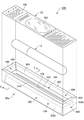
図1は、本発明の一実施形態に係る包装容器10の分解斜視図である。包装容器10は、容器本体20と、フィルム22とを有する。容器本体20内には、被収納品Xが収納された状態でフィルム22が接着される。本実施形態における被収納品Xは、化粧品(口紅等)であるが、その他の物を被収納品Xにしてもよい。
A. One Embodiment <A-1. Configuration of one embodiment>
[A-1-1. overall structure]
FIG. 1 is an exploded perspective view of a
[A−1−2.容器本体20]
(A−1−2−1.容器本体20の概要)
容器本体20は、上方が開口している直方体状である。また、容器本体20は、紙製(具体的には紙器用板紙製)である。図1に示すように、容器本体20は、底面部100と、第1側面部200と、第2側面部300と、第3側面部400と、第4側面部500とを有する。第1〜第4側面部200、300、400、500は、いずれも底面部100から上方に延在する。
[A-1-2. Container body 20]
(A-1-2-1. Outline of container body 20)
The
第2側面部300は、第1側面部200と対向する。第1側面部200及び第2側面部300は、長手方向の側面部である。第3側面部400は、第1側面部200及び第2側面部300に隣り合って配置される。第4側面部500は、第1側面部200及び第2側面部300に隣り合って配置されると共に、第3側面部400と対向する。第3側面部400及び第4側面部500は、幅方向の側面部である。底面部100、第1側面部200、第2側面部300、第3側面部400及び第4側面部500により、容器本体20の内部には、被収納品Xを収納する収納部600が形成される。
The second
(A−1−2−2.展開図の説明)
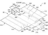
図2は、本実施形態に係る包装容器10の容器本体20の展開図である。図2において、実線は、展開状態の容器本体20の輪郭を示し、破線は、山折り部分を示し、一点鎖線は、谷折り部分を示す。図2に示すように、展開状態の容器本体20は、第1底面110と、第1大片部210と、第2大片部310と、第1小片部410と、第2小片部510とを有する。
(A-1-2-2. Explanation of development view)
FIG. 2 is a developed view of the
図2において、第1大片部210は、第1底面110の右側に位置する。第1大片部210は、組立状態の容器本体20において、主に第1側面部200を構成し、底面部100も構成する。図2において、第2大片部310は、第1底面110の左側に位置する。第2大片部310は、組立状態の容器本体20において、主に第2側面部300を構成し、底面部100も構成する。
In FIG. 2, the first
図2において、第1小片部410は、第1底面110の上側に位置する。第1小片部410は、組立状態の容器本体20において、主に第3側面部400を構成し、底面部100も構成する。図2において、第2小片部510は、第1底面110の下側に位置する。第2小片部510は、組立状態の容器本体20において、主に第4側面部500を構成し、底面部100も構成する。
In FIG. 2, the first
(A−1−2−3.容器本体20の組立方法)
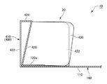
容器本体20の構造の理解を容易化するため、ここで容器本体20の組立方法を説明する。図3は、本実施形態に係る包装容器10の容器本体20の展開状態(初期状態)を示す斜視図である。図4及び図5は、本実施形態における組立時の容器本体20の第1・第2状態を示す図である。図6は、図5のA−A線断面図である。図7、図8及び図9は、本実施形態における組立時の容器本体20の第3・第4・第5状態を示す図である。図10は、図9のB−B線断面図である。図11は、本実施形態に係る包装容器10の容器本体20の組立完了状態を示す斜視図である。図12は、図11のC−C線断面図である。図13は、図11のD−D線断面図である。
(A-1-2-3. Assembling method of container body 20)
In order to facilitate understanding of the structure of the
容器本体20の組立てに際し、作業者は、第1小片部410を折り曲げて第3側面部400等を形作り(図4〜図6)、次いで第2小片部510を折り曲げて第4側面部500等を形作る(図7)。その後、作業者は、第1大片部210を折り曲げて第1側面部200等を形作り(図8〜図10)、次いで第2大片部310を折り曲げて第2側面部300等を形作り、容器本体20の組立てを完了する(図11〜図13)。
When assembling the
(A−1−2−4.底面部100)
次に、組立完了後の容器本体20の各部について説明する。まず底面部100から説明する。底面部100は、組立状態の容器本体20において下方に位置する部分であり、被収納品Xを下方から支持する。図1、図2等から理解されるように、底面部100は、矩形状である。
(A-1-2-4. Bottom part 100)
Next, each part of the
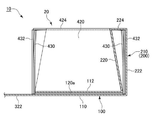
図12に示すように、底面部100は、第1底面110と、第1大片部210の第2底面112と、第2大片部310の第3底面114とが重なって形成される。第1底面110は、第1側面部200及び第2側面部300の第1外壁222、322(後述)と連続する(図2)。第2底面112は、第1側面部200の第1内壁220(後述)と連続する(図2)。また、図12に示すように、第2底面112は、第1底面110の上側に位置する。図12に示すように、第2底面112の先端側外縁は、第2側面部300の根元まで延在する。同様に、第3底面114は、第2側面部300の第1内壁320(後述)と連続する(図2)。また、図12に示すように、第3底面114は、第1底面110及び第2底面112の上側に位置する。図12に示すように、第3底面114の先端側外縁は、第1側面部200の根元まで延在する。
As shown in FIG. 12, the
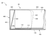
また、図13に示すように、底面部100は、第1小片部410の第4底面120aも含む。同様に、底面部100は、第2小片部510の第4底面120bも含む(図2参照)。第4底面120a、120bは、矩形状であり、第2内壁420、520の下縁と連続する。第1小片部410及び第2小片部510の第4底面120a、120bは、第1底面110と第2底面112の間に配置される。
Further, as shown in FIG. 13, the
(A−1−2−5.第1側面部200及び第2側面部300)
図12に示すように、第1側面部200は、第1内壁220と、第1外壁222と、第1上面224とを有する。第1内壁220は、底面部100から上方且つ内側に向かって延在する。図2に示すように、第1内壁220は、矩形状である。第1外壁222は、底面部100から上方に向かって延在する。図2に示すように、第1外壁222は、矩形状である。第1外壁222の高さ(図2の横方向)は、第1内壁220の高さより短い。第1外壁222の奥行き(図2の縦方向)は、第1内壁220の奥行きよりも長い。
(A-1-2-5. First
As shown in FIG. 12, the first
第1上面224は、第1内壁220の上縁と第1外壁222の上縁を連結し、底面部100と平行に配置される。図2に示すように、第1上面224は、台形状であり、短い底の奥行き(図2の縦方向)は、第1内壁220の奥行きと等しく、長い底の奥行きは、第1外壁222の奥行きと等しい。図12から明らかなように、第1側面部200の断面は、第1内壁220、第1外壁222及び第1上面224により逆三角形状となる。
The first
第2側面部300も第1側面部200と同様の構成を有する。すなわち、図12に示すように、第2側面部300は、第1内壁320と、第1外壁322と、第1上面324とを有する。第2側面部300の断面は、第1内壁320、第1外壁322及び第1上面324により逆三角形状となる。
The second
(A−1−2−6.第3側面部400及び第4側面部500)
図13に示すように、第3側面部400は、第2内壁420と、第2外壁422と、第2上面424とを有する。第2内壁420は、底面部100から上方且つ内側に向かって延在する。図2に示すように、第2内壁420は、台形状である。第2外壁422は、底面部100から上方に向かって延在する。図2に示すように、第2外壁422は、矩形状である。第2外壁422の高さ(図2の縦方向)は、第2内壁420の高さより短い。第2外壁422の幅(図2の横方向)は、第2内壁420の幅よりも長い。
(A-1-2-6. Third
As shown in FIG. 13, the third
第2上面424は、第2内壁420の上縁と第2外壁422の上縁を連結し、底面部100と平行に配置される。図2に示すように、第2上面424は、台形状であり、短い底の幅(図2の横方向)は、第1内壁420の短い底の幅と等しく、長い底の幅は、第1外壁422の幅と等しい。図13から明らかなように、第3側面部400の断面は、第2内壁420、第2外壁422及び第2上面424により逆三角形状となる。
The second
図2等から明らかなように、第3側面部400は、内側側面430と、外側側面432とを有する。内側側面430は、矩形状であり、第2内壁420の両側部と連続している。内側側面430の先端側の隅部には曲率が付されている。外側側面432は、矩形状であり、第2外壁422の両側部と連続している。外側側面432の先端側の上側隅部には曲率が付されている。
As is clear from FIG. 2 and the like, the third
図12に示すように、内側側面430及び外側側面432は、第1側面部200の第1内壁220及び第1外壁222の間及び第2側面部300の第1内壁320及び第1外壁322の間に挿入されている。第1小片部410を組み立てた状態(図5)では、内側側面430は、その上側が第2上面424よりも若干上側に位置している。そして、第1大片部210及び第2大片部310が組み立てられて第1上面224、324が内側側面430に被さった際、内側側面430は撓んで安定することとなる。これにより、第1側面部200及び第2側面部300に対して第3側面部400が位置ずれし難くなる。
As shown in FIG. 12, the
第4側面部500も第3側面部400と同様の構成を有する。すなわち、図2から明らかなように、第4側面部500は、第2内壁520と、第2外壁522と、第2上面524とを有する。第4側面部500の断面は、第2内壁520、第2外壁522及び第2上面524により逆三角形状となる。図2等から明らかなように、第4側面部500は、内側側面530と、外側側面532とを有する。
The fourth
[A−1−3.フィルム22(蓋部材)]
フィルム22(図1)は、熱接着により第1側面部200及び第2側面部300の第1上面224、324と、第3側面部400及び第4側面部500の第2上面424、524とに接着されている。接着方法は、熱接着以外の方法(例えば接着剤による接着)でもよい。
[A-1--3. Film 22 (closure member)]
The film 22 (FIG. 1) is heat-bonded to the first
図1に示すように、蓋部材であるフィルム22を透明なフィルムにした場合、印刷部分700と、非印刷部分702とを有する。被収納品Xの購買者等は、透明な非印刷部分702を介して被収納品Xを視認することができる。本実施形態のフィルム22は、透明基材と、印刷層と、熱接着用のシール層とを有する。フィルム22は、単層又は複数層のその他の構成としてもよい。本実施形態のフィルム22と容器本体20とは熱接着や接着剤により接着を行うものであり、用いられる手段としては印刷にてフィルムに塗工できるヒートシール剤をフィルム22の基材に印刷する手段や、容器本体と熱シールが可能なシーラントを積層する手段がある。
As shown in FIG. 1, when the
<A−2.本実施形態の包装容器10の製造方法>
本実施形態に係る包装容器10は、以下の製造方法により製造される。すなわち、作業者は、図3〜図13を参照して説明した方法で容器本体20を組み立てる。次いで、作業者は、容器本体20内に被収納品Xを挿入する。その後、作業者は、容器本体20にフィルム22を載せた状態で、図示しない熱接着装置を用いてフィルム22を容器本体20に熱接着する。
<A-2. Manufacturing method of
The
<A−3.本実施形態の効果>
以上のような本実施形態によれば、互いに対向する第1側面部200及び第2側面部300の断面は、第1内壁220、320、第1外壁222、322及び第1上面224、324により逆三角形状となる(図12)。これにより、底面部100に向かう方向の力が第1上面224、324に対して加えられても、第1側面部200及び第2側面部300は変形し難くなる。よって、包装容器10(特に容器本体20)の強度を向上することが可能となる。また、透明なフィルム20(蓋部材)を用いることで、包装容器10の中身である被収納品X(商品)を見せることができる。
<A-3. Effect of this embodiment>
According to the present embodiment as described above, the cross sections of the first
本実施形態において、包装容器10は、第1側面部200及び第2側面部300に隣り合って配置される第3側面部400と、第1側面部200及び第2側面部300に隣り合って配置され且つ第3側面部400と対向する第4側面部500とを備える(図1等)。第3側面部400及び第4側面部500それぞれは、底面部100から上方に向かって延在する第2内壁420、520と、底面部100から上方に向かって延在する第2外壁422、522と、第2内壁420、520の上縁と第2外壁422、522の上縁を連結し、底面部100と平行に配置される第2上面424、524とを有する(図13、図2等)。第3側面部400及び第4側面部500それぞれの断面は、第2内壁420、520、第2外壁422、522及び第2上面424、524により逆三角形状となる(図13)。
In the present embodiment, the
本実施形態によれば、第1〜第4側面部200、300、400、500の断面は、第1内壁220、320、第2内壁420、520、第1外壁222、322、第2外壁422,522、第1上面224、324及び第2上面424、524によりいずれも逆三角形状となる。これにより、底面部100に向かう方向の力が第1上面224、324及び第2上面424、524に対して加えられても、第1〜第4側面部200、300、400、500は変形し難くなる。よって、包装容器10の強度をさらに向上することが可能となる。
According to the present embodiment, the cross sections of the first to fourth
本実施形態において、包装容器10は、熱接着又は接着剤により第1上面224、324及び第2上面424、524に接着されているフィルム22(蓋部材)を備える(図1)。これにより、底面部100側に向かう力をかけてフィルム22を第1上面224、324及び第2上面424、524に接着させても、各側面部200、300、400、500の逆三角形状構造により強度を保つことが可能となる。また、蓋部材として透明なフィルム22を用いることで、包装容器10の中身である被収納品X(商品)を見せることができる。
In the present embodiment, the
本実施形態において、底面部100は、第1側面部200及び第2側面部300の第1外壁222、322と連続する第1底面110と、第1側面部200の第1内壁220と連続し、第1底面110の上側に位置する第2底面112と、第2側面部300の第1内壁320と連続し、第2底面112の上側に位置する第3底面114とを備える(図12)。また、第2底面112の先端側外縁は、第2側面部300の根元まで延在し、第3底面114の先端側外縁は、第1側面部200の根元まで延在する(図12)。さらに、第3側面部400及び第4側面部500それぞれは、第2内壁420、520の下縁と連続する第4底面120a、120bを備える(図13等)。第4底面120a、120bは、第1底面110と第2底面112の間に位置する(図13等)。
In the present embodiment, the
本実施形態によれば、第1底面110のみならず、第2底面112及び第3底面114を設けることにより、底面部100の強度を高めることが可能となる。また、第2底面112の先端側外縁は、第2側面部300の根元まで延在し、第3底面114の先端側外縁は、第1側面部200の根元まで延在する。これにより、第1側面部200及び第2側面部300それぞれの位置ずれ(図12における横方向)を抑制することが可能となる。
According to this embodiment, it is possible to increase the strength of the
さらに、本実施形態によれば、第3側面部400及び第4側面部500の第2内壁420、520の下縁と連続する第4底面120a、120bが、第1側面部200及び第2側面部300の第1外壁222、322と連続する第1底面110と第1側面部200の第1内壁220、320と連続する第2底面112(及び第2側面部300の第1内壁220、320と連続する第3底面114)の間に位置する。これにより、第3側面部400及び第4側面部500を底面部100及び第1側面部200(並びに第2側面部300)に対して簡易に固定することが可能となる。
Further, according to the present embodiment, the
本実施形態において、第3側面部400及び第4側面部500それぞれは、第2内壁420、520の両側部と連続する内側側面430、530と、第2外壁422、522の両側部と連続する外側側面432、532とを備える(図2等)。内側側面430、530及び外側側面432、532は、第1側面部200又は第2側面部300の第1内壁220、320及び第1外壁222、322の間に挿入されている(図12等)。これにより、第3側面部400及び第4側面部500を第1側面部200及び第2側面部300に対して簡易に固定することが可能となる。
In the present embodiment, each of the third
B.変形例
なお、本発明は、上記実施形態に限らず、本明細書の記載内容に基づき、種々の構成を採り得ることはもちろんである。例えば、以下の構成を採用することができる。
B. Modifications It should be noted that the present invention is not limited to the above-described embodiment, and it goes without saying that various configurations can be adopted based on the contents described in the present specification. For example, the following configuration can be adopted.
<B−1.容器本体20>
[B−1−1.全体]
上記実施形態において、容器本体20は、直方体状であった(図1等)。しかしながら、例えば、第1側面部200等の断面を逆三角形状とする観点からすれば、これに限らない。例えば、容器本体20は、四角錐台状であってもよい。
<B-1.
[B-1-1. Overall]
In the above embodiment, the
上記実施形態において、容器本体20は紙製(具体的には紙器用板紙製)であった。しかしながら、例えば、第1側面部200等の断面を逆三角形状とする観点からすれば、これに限らない。容器本体20は、例えば、紙器用板紙以外の紙製(例えば段ボール製)又はプラスチック製としてもよい。
In the above embodiment, the
上記実施形態において、容器本体20は、底面部100、第1側面部200、第2側面部300、第3側面部400及び第4側面部500を有していた(図1等)。しかしながら、別のフィルムやテープ等を用いる場合、紙としての第3側面部400及び第4側面部500を省略してもよい。或いは、包装容器10の用途によっては、第3側面部400及び第4側面部500の一方又は両方を省略してもよい。
In the above embodiment, the
[B−1−2.底面部100]
上記実施形態において、底面部100は、第1底面110、第2底面112、第3底面114及び第4底面120a、120bを有していた(図12、図13等)。しかしながら、例えば、第1側面部200等の断面を逆三角形状とする観点からすれば、これに限らない。例えば、第2底面112、第3底面114及び第4底面120a、120bの1つ又は複数を省略してもよい。
[B-1-2. Bottom part 100]
In the above embodiment, the
図14は、本発明の変形例に係る包装容器10Aの分解斜視図である。図15は、前記変形例に係る包装容器10Aの容器本体20aの展開図である。図16は、被収納品Xが容器本体20aに収容され、フィルム22が容器本体20aに接着された状態において図14のE−E線で切断した断面図である。
FIG. 14 is an exploded perspective view of the
図15及び図16に示すように、本変形例の容器本体20の第2大片部310aは、上記実施形態の第3底面114の代わりに台状部330を有する。台状部330は、側方壁332a、332bと、台座面334とを有する。図16に示すように、両側方壁332a、332bは、第1内壁220、320に沿って上方且つ内側に延在する。台座面334は、側方壁332a、332bの上縁を連結する。また、台座面334の中央には、貫通孔336が形成されている。そのため、台状部330は、被収納品Xの一部が貫通孔336に入り込んだ状態で被収納品Xを支持する。これにより、被収納品Xの位置ずれを防止し易くなる。さらに、側方壁332a、332bが、第1内壁220、320に沿って配置されるため、図16における横方向の力に対して変形し難くなる。
As shown in FIGS. 15 and 16, the second
上記実施形態では、第2底面112の先端側外縁は、第2側面部300の根元まで延在し、第3底面114の先端側外縁は、第1側面部200の根元まで延在していた(図12)。しかしながら、例えば、第1側面部200等の断面を逆三角形状とする観点からすれば、これに限らない。例えば、第2底面112の先端側外縁又は第3底面114の先端側外縁は、図12の横方向の半分まで到達しない長さとしてもよい。
In the above embodiment, the tip-side outer edge of the second
[B−1−3.第1側面部200〜第4側面部500]
上記実施形態において、第1側面部200、第2側面部300、第3側面部400及び第4側面部500いずれの断面も逆三角形状とした(図12、図13等)。しかしながら、例えば、第1側面部200又は第2側面部300の断面を逆三角形状とする観点からすれば、これに限らない。例えば、第1側面部200、第2側面部300のみを逆三角形状としてもよい。
[B-1--3. 1st
In the above embodiment, the cross sections of the first
上記実施形態において、第1内壁220、320は、底面部100から上方且つ内側に向かって延在し、第1外壁222、322は、底面部100から垂直方向に向かって延在した(図12)。しかしながら、例えば、逆三角形状を構成する観点からすれば、これに限らない。例えば、第1内壁220、320は、底面部100から上方且つ内側に向かって延在し、第1外壁222、322は、底面部100から上方且つ外側に向かって延在してもよい。第2内壁420、420及び第2外壁422、522についても同様である。
In the above embodiment, the first
<B−2.フィルム22>
上記実施形態では、フィルム22に、印刷部分700と非印刷部分702を設けた(図1)。しかしながら、例えば、容器本体20の開口部を塞ぐ観点からすれば、フィルム22は、印刷部分700のみ又は非印刷部分702のみから構成してもよい。
<B-2.
In the above embodiment, the
上記実施形態では、容器本体20の開口部を塞ぐ蓋部材としてフィルム22を用いた(図1)。しかしながら、例えば、容器本体20の開口部を塞ぐ観点からすれば、フィルム22以外の蓋部材を用いてもよい。或いは、例えば、第1側面部200等の断面を逆三角形状とする観点からすれば、フィルム22(蓋部材)を省略してもよい。
In the above embodiment, the
10、10A…包装容器 20、20a…容器本体
22…フィルム(蓋部材) 100…底面部
110…第1底面 112…第2底面
114…第3底面 120a、120b…第4底面
200…第1側面部 220、320…第1内壁
222、322…第1外壁 224、324…第1上面
300…第2側面部 400…第3側面部
420、520…第2内壁 422、522…第2外壁
424、524…第2上面 430、530…内側側面
432、532…外側側面 500…第4側面部
10, 10A ...
Claims (5)
前記底面部から上方に延在する第1側面部と、
前記底面部から上方に延在し、前記第1側面部と対向する第2側面部と
を備える容器本体を有する包装容器であって、
前記第1側面部及び前記第2側面部それぞれは、
前記底面部から上方に向かって延在する第1内壁と、
前記底面部から上方に向かって延在する第1外壁と、
前記第1内壁の上縁と前記第1外壁の上縁を連結し、前記底面部と平行に配置される第1上面と
を有し、
前記第1側面部及び前記第2側面部それぞれの断面は、前記第1内壁、前記第1外壁及び前記第1上面により逆三角形状となる
ことを特徴とする包装容器。 The bottom part and
A first side surface portion extending upward from the bottom surface portion and
A packaging container having a container body extending upward from the bottom surface portion and having a second side surface portion facing the first side surface portion.
Each of the first side surface portion and the second side surface portion
The first inner wall extending upward from the bottom surface and
The first outer wall extending upward from the bottom surface and
It has a first upper surface that connects the upper edge of the first inner wall and the upper edge of the first outer wall and is arranged in parallel with the bottom surface portion.
A packaging container characterized in that the cross section of each of the first side surface portion and the second side surface portion has an inverted triangular shape due to the first inner wall, the first outer wall, and the first upper surface.
前記包装容器は、
前記第1側面部及び前記第2側面部に隣り合って配置される第3側面部と、
前記第1側面部及び前記第2側面部に隣り合って配置され且つ前記第3側面部と対向する第4側面部と
を備え、
前記第3側面部及び前記第4側面部それぞれは、
前記底面部から上方に向かって延在する第2内壁と、
前記底面部から上方に向かって延在する第2外壁と、
前記第2内壁の上縁と前記第2外壁の上縁を連結し、前記底面部と平行に配置される第2上面と
を有し、
前記第3側面部及び前記第4側面部それぞれの断面は、前記第2内壁、前記第2外壁及び前記第2上面により逆三角形状となる
ことを特徴とする包装容器。 In the packaging container according to claim 1,
The packaging container is
A third side surface portion arranged adjacent to the first side surface portion and the second side surface portion, and
A fourth side surface portion which is arranged adjacent to the first side surface portion and the second side surface portion and faces the third side surface portion is provided.
Each of the third side surface portion and the fourth side surface portion
A second inner wall extending upward from the bottom surface,
A second outer wall extending upward from the bottom surface and
It has a second upper surface that connects the upper edge of the second inner wall and the upper edge of the second outer wall and is arranged in parallel with the bottom surface portion.
A packaging container characterized in that the cross section of each of the third side surface portion and the fourth side surface portion has an inverted triangular shape due to the second inner wall, the second outer wall, and the second upper surface.
熱接着又は接着剤により少なくとも前記第1上面に接着されている蓋部材をさらに備える
ことを特徴とする包装容器。 In the packaging container according to claim 1 or 2.
A packaging container further comprising a lid member that is adhered to at least the first upper surface by heat adhesion or an adhesive.
前記底面部は、
前記第1側面部及び前記第2側面部の前記第1外壁と連続する第1底面と、
前記第1側面部の前記第1内面と連続し、前記第1底面の上側に位置する第2底面と、
前記第2側面部の前記第1内面と連続し、前記第2底面の上側に位置する第3底面と
を備え、
前記第2底面の先端側外縁は、前記第2側面部の根元まで延在し、
前記第3底面の先端側外縁は、前記第1側面部の根元まで延在し、
前記第3側面部及び前記第4側面部それぞれは、前記第2内壁の下縁と連続する第4底面を備え、
前記第4底面は、前記第1底面と前記第2底面の間に位置する
ことを特徴とする包装容器。 In the packaging container according to claim 2 or claim 3, which is subordinate to claim 2.
The bottom surface
A first bottom surface continuous with the first outer wall of the first side surface portion and the second side surface portion, and
A second bottom surface that is continuous with the first inner surface of the first side surface portion and is located above the first bottom surface,
It is provided with a third bottom surface that is continuous with the first inner surface of the second side surface portion and is located above the second bottom surface.
The tip-side outer edge of the second bottom surface extends to the root of the second side surface portion.
The tip-side outer edge of the third bottom surface extends to the root of the first side surface portion.
Each of the third side surface portion and the fourth side surface portion has a fourth bottom surface continuous with the lower edge of the second inner wall.
The fourth bottom surface is a packaging container characterized in that it is located between the first bottom surface and the second bottom surface.
前記第3側面部及び前記第4側面部それぞれは、
前記第2内壁の両側部と連続する内側側面と、
前記第2外壁の両側部と連続する外側側面と
を備え、
前記内側側面及び前記外側側面は、前記第1側面部及び前記第2側面部の前記第1内壁及び前記第1外壁の間に挿入されている
ことを特徴とする包装容器。
In the packaging container according to claim 2 or 4, or claim 3, which is subordinate to claim 2.
Each of the third side surface portion and the fourth side surface portion
An inner side surface continuous with both sides of the second inner wall,
It is provided with both sides of the second outer wall and continuous outer side surfaces.
A packaging container characterized in that the inner side surface and the outer side surface are inserted between the first inner wall portion and the first outer wall portion of the first side surface portion and the second side surface portion.
Priority Applications (1)
| Application Number | Priority Date | Filing Date | Title |
|---|---|---|---|
| JP2020077447A JP7490917B2 (en) | 2020-04-24 | 2020-04-24 | Packaging Containers |
Applications Claiming Priority (1)
| Application Number | Priority Date | Filing Date | Title |
|---|---|---|---|
| JP2020077447A JP7490917B2 (en) | 2020-04-24 | 2020-04-24 | Packaging Containers |
Publications (2)
| Publication Number | Publication Date |
|---|---|
| JP2021172376A true JP2021172376A (en) | 2021-11-01 |
| JP7490917B2 JP7490917B2 (en) | 2024-05-28 |
Family
ID=78279154
Family Applications (1)
| Application Number | Title | Priority Date | Filing Date |
|---|---|---|---|
| JP2020077447A Active JP7490917B2 (en) | 2020-04-24 | 2020-04-24 | Packaging Containers |
Country Status (1)
| Country | Link |
|---|---|
| JP (1) | JP7490917B2 (en) |
Citations (8)
| Publication number | Priority date | Publication date | Assignee | Title |
|---|---|---|---|---|
| JPS51106628U (en) * | 1975-02-24 | 1976-08-26 | ||
| JPS5638019U (en) * | 1979-08-31 | 1981-04-10 | ||
| JPS6013318U (en) * | 1983-07-07 | 1985-01-29 | 石井 和則 | Corrugated paper assembly box |
| JP2000309375A (en) * | 1999-04-23 | 2000-11-07 | Toppan Printing Co Ltd | Paper lid |
| JP2002068169A (en) * | 2000-08-28 | 2002-03-08 | Tanaka Shiko:Kk | Paper cool box |
| JP2002347840A (en) * | 2001-05-30 | 2002-12-04 | Dainippon Printing Co Ltd | Packaging container |
| JP2016078852A (en) * | 2014-10-10 | 2016-05-16 | タキロン株式会社 | Packing method for plate products and cardboard box therefor |
| JP2016130135A (en) * | 2015-01-14 | 2016-07-21 | 王子ホールディングス株式会社 | Assembly box and blank sheet, and primary assembly sheet |
-
2020
- 2020-04-24 JP JP2020077447A patent/JP7490917B2/en active Active
Patent Citations (8)
| Publication number | Priority date | Publication date | Assignee | Title |
|---|---|---|---|---|
| JPS51106628U (en) * | 1975-02-24 | 1976-08-26 | ||
| JPS5638019U (en) * | 1979-08-31 | 1981-04-10 | ||
| JPS6013318U (en) * | 1983-07-07 | 1985-01-29 | 石井 和則 | Corrugated paper assembly box |
| JP2000309375A (en) * | 1999-04-23 | 2000-11-07 | Toppan Printing Co Ltd | Paper lid |
| JP2002068169A (en) * | 2000-08-28 | 2002-03-08 | Tanaka Shiko:Kk | Paper cool box |
| JP2002347840A (en) * | 2001-05-30 | 2002-12-04 | Dainippon Printing Co Ltd | Packaging container |
| JP2016078852A (en) * | 2014-10-10 | 2016-05-16 | タキロン株式会社 | Packing method for plate products and cardboard box therefor |
| JP2016130135A (en) * | 2015-01-14 | 2016-07-21 | 王子ホールディングス株式会社 | Assembly box and blank sheet, and primary assembly sheet |
Also Published As
| Publication number | Publication date |
|---|---|
| JP7490917B2 (en) | 2024-05-28 |
Similar Documents
| Publication | Publication Date | Title |
|---|---|---|
| JP6240476B2 (en) | Packing box sheet and package | |
| JP2012140140A (en) | Sheet connection structure of packaging case and the packaging case | |
| JP5288327B2 (en) | Paper carton | |
| JP2014156276A (en) | Packing box | |
| JP7490917B2 (en) | Packaging Containers | |
| JP6007621B2 (en) | Composite container with outer box and inner bag, and paper container | |
| JP4549574B2 (en) | Packaging container | |
| JP2008068885A (en) | Food storage and cooking paper containers | |
| JP6083238B2 (en) | Packaging box | |
| JP2014005008A (en) | Composite container with outer case and inner bag, paper container, and blank plate for manufacturing the same | |
| JP2012201396A (en) | Packaging box | |
| JP6937493B2 (en) | Foldable packaging box | |
| JP4103422B2 (en) | Carton with buffer plate | |
| JP3730602B2 (en) | Packaging box | |
| JP3235381U (en) | Box sheet | |
| JP2008056262A (en) | Packaging box | |
| JP3235369U (en) | Packaging box | |
| JP2023176998A (en) | box | |
| JP7463703B2 (en) | Packaging box | |
| JP3229162U (en) | Box sheet | |
| JP5572472B2 (en) | Connecting container | |
| JP3209896U (en) | Sheet set | |
| JP6399819B2 (en) | Packaging box | |
| JP2535140Y2 (en) | carton | |
| JP2024093291A (en) | Carton Container |
Legal Events
| Date | Code | Title | Description |
|---|---|---|---|
| A621 | Written request for application examination |
Free format text: JAPANESE INTERMEDIATE CODE: A621 Effective date: 20230414 |
|
| A977 | Report on retrieval |
Free format text: JAPANESE INTERMEDIATE CODE: A971007 Effective date: 20231115 |
|
| A131 | Notification of reasons for refusal |
Free format text: JAPANESE INTERMEDIATE CODE: A131 Effective date: 20231121 |
|
| A521 | Request for written amendment filed |
Free format text: JAPANESE INTERMEDIATE CODE: A523 Effective date: 20240122 |
|
| TRDD | Decision of grant or rejection written | ||
| A01 | Written decision to grant a patent or to grant a registration (utility model) |
Free format text: JAPANESE INTERMEDIATE CODE: A01 Effective date: 20240402 |
|
| A61 | First payment of annual fees (during grant procedure) |
Free format text: JAPANESE INTERMEDIATE CODE: A61 Effective date: 20240419 |
|
| R150 | Certificate of patent or registration of utility model |
Ref document number: 7490917 Country of ref document: JP Free format text: JAPANESE INTERMEDIATE CODE: R150 |