JP2021161817A - Junction structure and junction method - Google Patents
Junction structure and junction method Download PDFInfo
- Publication number
- JP2021161817A JP2021161817A JP2020066749A JP2020066749A JP2021161817A JP 2021161817 A JP2021161817 A JP 2021161817A JP 2020066749 A JP2020066749 A JP 2020066749A JP 2020066749 A JP2020066749 A JP 2020066749A JP 2021161817 A JP2021161817 A JP 2021161817A
- Authority
- JP
- Japan
- Prior art keywords
- steel plate
- perforated steel
- wall
- plate gibber
- frame
- Prior art date
- Legal status (The legal status is an assumption and is not a legal conclusion. Google has not performed a legal analysis and makes no representation as to the accuracy of the status listed.)
- Granted
Links
Images



Landscapes
- Load-Bearing And Curtain Walls (AREA)
- Joining Of Building Structures In Genera (AREA)
- Reinforcement Elements For Buildings (AREA)
Abstract
Description
本発明は、フレームとフレーム構面内の壁体とを接合する接合構造および接合方法に関する。 The present invention relates to a joining structure and a joining method for joining a frame and a wall body in a frame structure.
鉄骨造(S造)の柱や梁を有するフレームの構面内に鉄筋コンクリート造(RC造)の耐震壁を設けることは多く、その際のフレームと耐震壁の接合構造として、鉄骨造の梁に設けた頭付きスタッドを耐震壁に埋設するものがある(特許文献1参照)。 Reinforced concrete (RC) shear walls are often provided in the structure of frames with steel (S) columns and beams, and as a joint structure between the frame and the shear walls, steel beams are used. Some of the provided headed studs are embedded in the earthquake-resistant wall (see Patent Document 1).
また、柱や梁の鉄骨を鉄筋コンクリートで巻き、このコンクリートを耐震壁と連続させる構造も、新築の構造設計において一般的に用いられている。 In addition, a structure in which the steel frames of columns and beams are wrapped with reinforced concrete and the concrete is connected to the earthquake-resistant wall is also generally used in the structural design of new construction.
さらに特許文献2には、鉄骨造の梁に支圧片とアンカー鉄筋を溶接し、支圧片とアンカー鉄筋を耐震壁に埋設させる構造が開示されている。 Further, Patent Document 2 discloses a structure in which a bearing piece and an anchor reinforcing bar are welded to a steel beam and the bearing piece and the anchor reinforcing bar are embedded in a seismic wall.
頭付きスタッドによるフレームと耐震壁の接合を行う場合、スタッド1本当たりのせん断耐力が小さく接合部分の剛性が弱いため、フレームと耐震壁との一体性の面で課題がある。また各種合成構造設計指針によれば、頭付きスタッドと耐震壁の壁筋との一体化のため、スパイラル筋を耐震壁に別途埋設することが必要になる。 When joining a frame and a shear wall with a headed stud, the shear strength per stud is small and the rigidity of the joint is weak, so there is a problem in terms of the integrity of the frame and the shear wall. In addition, according to various synthetic structure design guidelines, it is necessary to separately bury the spiral reinforcement in the shear wall in order to integrate the headed stud and the wall reinforcement of the shear wall.
柱や梁の鉄骨に鉄筋コンクリートを巻き、このコンクリートを耐震壁と連続させる場合、柱や梁を鉄骨鉄筋コンクリート造(SRC造)とするため施工手間が大きいという課題がある。また柱や梁の部材断面が大きくなり、建物の使用可能面積の減少につながる。特許文献2も、支圧片に加え、アンカー鉄筋の溶接を梁に行っており、その分、余計な施工手間がかかる。 When reinforced concrete is wrapped around the steel frames of columns and beams and this concrete is connected to the earthquake-resistant wall, there is a problem that the construction time is large because the columns and beams are made of steel-framed reinforced concrete (SRC structure). In addition, the cross section of columns and beams becomes large, which leads to a decrease in the usable area of the building. In Patent Document 2, in addition to the bearing piece, the anchor reinforcing bar is welded to the beam, which requires extra construction work.
本発明は上記の問題に鑑みてなされたものであり、フレームとフレーム構面内の壁体とを容易に一体化できる接合構造等を提供することを目的とする。 The present invention has been made in view of the above problems, and an object of the present invention is to provide a joint structure or the like in which a frame and a wall body in a frame structure can be easily integrated.
前述した課題を解決するための第1の発明は、鉄骨造の柱または梁を少なくとも有するフレームと、前記フレームに囲まれた鉄筋コンクリート造の壁体との接合構造であって、鉄骨造の柱または梁の少なくともいずれかに孔あき鋼板ジベルが設けられ、前記孔あき鋼板ジベルが前記壁体内に埋設され、前記孔あき鋼板ジベルの孔に、前記壁体の縦筋または横筋、もしくは縦筋と横筋のいずれかに固定される鉄筋が通されたことを特徴とする接合構造である。 The first invention for solving the above-mentioned problems is a joint structure of a frame having at least steel columns or beams and a reinforced concrete wall surrounded by the frames, and is a steel columns or beams. A perforated steel plate gibber is provided in at least one of the beams, and the perforated steel plate gibber is embedded in the wall. It is a joint structure characterized in that a reinforcing bar fixed to any of the above is passed through.
本発明では、フレームを構成する鉄骨造の梁や柱に孔あき鋼板ジベルを取付け、これをフレーム構面内の壁体に埋設することで、フレームと壁体をせん断耐力の大きな孔あき鋼板ジベルにより一体化できる。しかも、壁体内の壁筋(縦筋や横筋)あるいはこれに固定される鉄筋を孔あき鋼板ジベルの孔に通すことで、壁体の配筋を利用して合理的に孔あき鋼板ジベルのせん断耐力を高めることができ、より大きな力の伝達を可能にしてフレームと壁体との一体性が向上する。また本発明では前記したスパイラル筋やアンカー鉄筋が不要であり、梁や柱の鉄骨を鉄筋コンクリートで巻く必要も無いので、フレームの有効開口面積の減少もなく、従って建物の使用可能面積が減少することも無い。また、その分の施工手間も削減できる。 In the present invention, a perforated steel plate gibber is attached to a steel beam or column constituting the frame, and the perforated steel plate gibber is embedded in the wall body in the frame structure to attach the frame and the wall body to a perforated steel plate gibber having a large shear strength. Can be integrated by. Moreover, by passing the wall reinforcements (vertical and horizontal reinforcements) in the wall or the reinforcing bars fixed to them through the holes of the perforated steel plate gibber, the shearing of the perforated steel plate gibber can be reasonably performed by utilizing the reinforcement arrangement of the wall body. The proof stress can be increased, and a larger force can be transmitted to improve the unity between the frame and the wall body. Further, in the present invention, the spiral bar and the anchor reinforcing bar described above are not required, and the steel frame of the beam or column does not need to be wrapped with reinforced concrete. Therefore, the effective opening area of the frame is not reduced, and therefore the usable area of the building is reduced. There is no. In addition, the construction work can be reduced accordingly.
前記孔あき鋼板ジベルは、例えば脚部とフランジ部からなるT字状の断面を有し、前記フランジ部に設けられた前記孔に、前記壁体の縦筋または横筋が通される。
この場合、縦筋や横筋を直接孔に通すことができ、施工性が向上する。
The perforated steel plate gibber has, for example, a T-shaped cross section including a leg portion and a flange portion, and vertical or horizontal streaks of the wall body are passed through the holes provided in the flange portion.
In this case, the vertical and horizontal bars can be passed directly through the hole, and the workability is improved.
あるいは、前記孔あき鋼板ジベルは平板状であり、前記孔に、前記壁体の縦筋と横筋のいずれかに固定されたコの字状の鉄筋の折り返し部分が通される。
この場合、コの字筋と壁体のコンクリートとの付着により、ジベルとコンクリートとの間の開きを抑制し、孔あき鋼板ジベルのせん断耐力を向上させることができる。
Alternatively, the perforated steel plate gibber has a flat plate shape, and a folded portion of a U-shaped reinforcing bar fixed to either a vertical bar or a horizontal bar of the wall body is passed through the hole.
In this case, the adhesion between the U-shaped streak and the concrete of the wall body can suppress the opening between the gibber and the concrete, and improve the shear strength of the perforated steel plate gibber.
第2の発明は、鉄骨造の柱または梁を少なくとも有するフレームと、前記フレームに囲まれた鉄筋コンクリート造の壁体との接合方法であって、鉄骨造の柱または梁の少なくともいずれかに設けられる孔あき鋼板ジベルの孔に、前記壁体の縦筋または横筋、もしくは縦筋と横筋のいずれかに固定される鉄筋を通し、前記孔あき鋼板ジベルを前記壁体内に埋設することを特徴とする接合方法である。 The second invention is a method of joining a frame having at least a steel-framed column or beam and a reinforced concrete wall surrounded by the frame, and is provided on at least one of the steel-framed columns or beams. It is characterized in that the perforated steel plate gibber is embedded in the wall by passing a reinforcing bar fixed to either the vertical or horizontal streaks of the wall body or either the vertical streaks and the horizontal streaks through the holes of the perforated steel plate gibber. It is a joining method.
本発明により、フレームとフレーム構面内の壁体とを容易に一体化できる接合構造等を提供することができる。 INDUSTRIAL APPLICABILITY According to the present invention, it is possible to provide a joint structure or the like in which a frame and a wall body in a frame structure can be easily integrated.
以下、図面に基づいて本発明の好適な実施形態について詳細に説明する。 Hereinafter, preferred embodiments of the present invention will be described in detail with reference to the drawings.
[第1の実施形態]
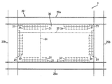
図1は本発明の第1の実施形態に係る接合構造1を示す図である。接合構造1は、フレーム20とフレーム構面内の耐震壁30とを接合するものである。
[First Embodiment]
FIG. 1 is a diagram showing a
フレーム20は、鉄骨造の梁20aと鉄骨造の柱20bを有する。梁20aは例えばH形鋼による鉄骨梁であり、柱20bは例えばコンクリート充填鋼管柱や鉄骨柱であるが、これらに限定されることはない。
The
耐震壁30は、フレーム20に囲まれた鉄筋コンクリート造の壁体である。耐震壁30の内部には、壁筋として縦筋31と横筋32が埋設される。縦筋31は鉛直方向の鉄筋であり、水平方向に間隔を空けて複数本配置される。横筋32は水平方向の鉄筋であり、鉛直方向に間隔を空けて複数本配置される。図1では、一部を除き、縦筋31と横筋32の中間部を省略して図示している。
The earthquake-
接合構造1は、梁20aと柱20bの耐震壁30側の面に孔あき鋼板ジベル21を設置し、これを耐震壁30の内部に埋設したものである。孔あき鋼板ジベル21は、孔内に充填されるコンクリートのせん断抵抗によりフレーム20と耐震壁30を一体化する補強材であり、孔あき鋼板ジベル21によりせん断力を伝達することで、耐震壁30の応力をフレーム20に流すことができる。
In the
また本実施形態では、孔あき鋼板ジベル21を耐震壁30内に埋設するだけでなく、その孔に縦筋31や横筋32を通すことで、1孔当たりのせん断耐力を大きくすることができる。
Further, in the present embodiment, not only the perforated
図2(a)、(b)は孔あき鋼板ジベル21付近の断面を示す図である。図2(a)は耐震壁30の上方の梁20aに取り付けた孔あき鋼板ジベル21を示したものであり、図2(b)は耐震壁30の下方の梁20aに取り付けた孔あき鋼板ジベル21を示したものである。図2(a)、(b)は梁20aの軸方向と直交する断面を見たものである。
2 (a) and 2 (b) are views showing a cross section in the vicinity of the perforated
本実施形態の孔あき鋼板ジベル21は、脚部21aとフランジ部21bからなるT字状の断面を有する。孔あき鋼板ジベル21には例えばカットT形鋼が用いられ、その脚部21aを隅肉溶接(不図示)により梁20aに取付け、脚部21aの板面が梁20aの軸方向(図2(a)、(b)の紙面法線方向に対応する)に沿うように配置する。
The perforated
孔あき鋼板ジベル21のフランジ部21bには孔211が設けられ、この孔211に縦筋31が通される。なお、縦筋31の上端部は図2(a)に示すように梁20aの下フランジとの間に間隔を空けて配置されるが、縦筋31の下端部は図2(b)に示すように梁20aの上フランジ上に載せて配置される。
A
図2(c)に示すように、孔211は孔あき鋼板ジベル21の長手方向(梁20aの軸方向に対応する)に間隔を空けて複数配置され、図の例では各孔211に縦筋31が通される。本実施形態では、縦筋31を孔211に通すだけで孔あき鋼板ジベル21の1孔あたりのせん断耐力が高まり、施工が容易である。
As shown in FIG. 2C, a plurality of
本実施形態では、柱20bにも同様の孔あき鋼板ジベル21が取付けられており、横筋32の両端部が図2(a)の例と同様に孔あき鋼板ジベル21の孔211に通される。
In the present embodiment, the same perforated
梁20aおよび柱20bにおいて、孔あき鋼板ジベル21の配置は任意に設定可能であり、より短い孔あき鋼板ジベル21を梁20aや柱20bの軸方向に多数並べて配置することも可能である。
The arrangement of the perforated
孔あき鋼板ジベル21の長さや断面形状は、耐震壁30が負担可能なせん断力または耐震壁30に負担させたいせん断力を決定した後、そのせん断力と耐震壁30の形状より、梁20a(または柱20b)と耐震壁30の間で移行させるべきせん断力を算定し、当該せん断力に抵抗するために必要な孔211の数を求め、その数に応じて定めることができる。また孔あき鋼板ジベル21の脚部21aの溶接位置でのせん断応力も考慮し、当該せん断応力が許容耐力以下となるように設定する。
For the length and cross-sectional shape of the perforated
孔あき鋼板ジベル21の各部位の寸法に対する孔211の径やピッチの設定については、基本的には、孔あき鋼板ジベル21の脚部21aの溶接位置での許容耐力(せん断耐力)よりも、孔211内のコンクリートの許容耐力が小さくなるように定める。
Regarding the setting of the diameter and pitch of the
なお、孔211の径は、耐震壁30の壁厚にもよるが例えば40mm〜80mm程度とし、耐震壁30のコンクリートの粗骨材が通るだけの大きさとする。通常、縦筋31や横筋32の径は10mm〜22mm程度なので、粗骨材が通る大きさに設定すれば、縦筋31や横筋32も問題無く挿通することができる。
The diameter of the
本実施形態の接合構造1は、フレーム20と耐震壁30を同時に施工する新築の場合にも、既存のフレーム20の構面内に後から耐震壁30を施工する補強工事においても適用することが可能である。いずれにおいても、鉄骨造の梁20aや柱20bに設けた孔あき鋼板ジベル21の孔211に縦筋31や横筋32を通した後、孔あき鋼板ジベル21を耐震壁30のコンクリート内に埋設すればよい。新築の場合、孔あき鋼板ジベル21は予め工場で梁20aや柱20bに溶接しておくことで、現場施工(現場溶接)手間の削減に繋がる。ただし、梁20aや柱20bの建方後、孔あき鋼板ジベル21の現場溶接を行うことも可能である。
The
以上説明したように、本実施形態によれば、フレーム20を構成する鉄骨造の梁20aや柱20bに孔あき鋼板ジベル21を取付け、これを耐震壁30に埋設することで、フレーム20とフレーム構面内の耐震壁30とをせん断耐力の大きな孔あき鋼板ジベル21により一体化できる。しかも、耐震壁30内の壁筋(縦筋31や横筋32)を孔あき鋼板ジベル21の孔211に通すことで、耐震壁30の配筋を利用して合理的に孔あき鋼板ジベル21のせん断耐力を高めることができ、より大きな力の伝達を可能にしてフレーム20と耐震壁30との一体性が向上する。
As described above, according to the present embodiment, the
また本実施形態では前記したスパイラル筋やアンカー鉄筋が不要であり、梁20aや柱20bの鉄骨を鉄筋コンクリートで巻く必要も無いので、フレーム20の有効開口面積の減少もなく、従って建物の使用可能面積が減少することもない。また、その分の施工手間も削減できる。
Further, in the present embodiment, the spiral bar and the anchor reinforcing bar described above are not required, and the steel frame of the
また本実施形態では壁筋を孔あき鋼板ジベル21の孔211に直接通すことができ、施工性が向上する。さらに、T字状の孔あき鋼板ジベル21は耐震壁30との一体性が高く、ひいては孔あき鋼板ジベル21を取付けたフレーム20と耐震壁30との一体性が高まることで、フレーム20と耐震壁30の間の目開きが抑制される。
Further, in the present embodiment, the wall reinforcement can be directly passed through the
しかしながら、本発明は以上の実施形態に限らない。例えば本実施形態では孔あき鋼板ジベル21の全ての孔211に壁筋の端部を通しているが、全ての孔211に壁筋の端部を通すことは必須ではない。ただし、孔211に壁筋の端部を通すことで壁筋の端部を定着に近い状態とできるので、全ての孔211に壁筋を通すことができれば壁筋の施工面で望ましく、また孔あき鋼板ジベル21の1孔あたりのせん断耐力が高いことで孔数の削減にもつながる。
However, the present invention is not limited to the above embodiments. For example, in the present embodiment, the ends of the wall bars are passed through all the
また、配筋の安定性を考慮すると、梁20aに取付けた孔あき鋼板ジベル21の複数の孔211のそれぞれから梁20a側に突出する複数の縦筋31の端部を、図示しない水平方向の段取り筋に結束することも望ましい。同様に、柱20bに取付けた孔あき鋼板ジベル21の複数の孔211のそれぞれから柱20b側に突出する複数の横筋32の端部を、図示しない鉛直方向の段取り筋に結束することも望ましい。また、これら複数の縦筋31や横筋32の端部をフック状に折り曲げ、より定着力を高めることも考えられる。
Further, in consideration of the stability of the reinforcement arrangement, the ends of the plurality of
さらに、孔あき鋼板ジベル21の脚部21aに縦筋31や横筋32の通されない孔(不図示)を設けてもよく、この孔に耐震壁30のコンクリートが充填されることで孔あき鋼板ジベル21のせん断耐力が向上する。
Further, the
また本実施形態では鉄骨造の梁20aと柱20bの双方に孔あき鋼板ジベル21を設けているが、いずれか一方にのみ孔あき鋼板ジベル21を設けてもよい。また柱20bを鉄筋コンクリート造や鉄骨鉄筋コンクリート造(SRC造)とする場合もあり、この場合は鉄骨造の梁20aに孔あき鋼板ジベル21を設ければよい。さらに、耐震壁30の下方の梁20aが鉄筋コンクリート造の基礎梁などである場合もあり、この場合は鉄骨造の柱20b、あるいは耐震壁30の上方の鉄骨造の梁20aの少なくともいずれかに孔あき鋼板ジベル21を設ければよい。
Further, in the present embodiment, the perforated
以下、本発明の別の例を第2の実施形態として説明する。第2の実施形態は第1の実施形態と異なる構成について説明し、同様の構成については図等で同じ符号を付すなどして説明を省略する。 Hereinafter, another example of the present invention will be described as a second embodiment. The second embodiment describes a configuration different from that of the first embodiment, and the same configurations will be omitted by adding the same reference numerals in figures and the like.
[第2の実施形態]
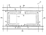
図3は本発明の第2の実施形態に係る接合構造1aを示す図である。本実施形態の接合構造1aでは、T字状の孔あき鋼板ジベル21に代えて平板状の孔あき鋼板ジベル22が用いられる。
[Second Embodiment]
FIG. 3 is a diagram showing a
図4(a)、(b)は孔あき鋼板ジベル22付近の断面を図2(a)、(b)と同様に示す図である。上記したように、本実施形態の孔あき鋼板ジベル22は平板状であり、鋼板等が用いられる。孔あき鋼板ジベル22は、その側辺が隅肉溶接(不図示)によって梁20aに取付けられ、板面が梁20aの軸方向(図4(a)、(b)の紙面法線方向に対応する)に沿うように配置される。
4 (a) and 4 (b) are views showing a cross section of the vicinity of the perforated
孔あき鋼板ジベル22の孔221には、コの字筋33の折り返し部分が通される。コの字筋33はコの字状の鉄筋であり、その両端部が不図示の結束材により縦筋31に結束されて固定される。なお、本実施形態でも縦筋31の上端部は梁20aの下フランジとの間に間隔を空けて配置され、下端部は梁20aの上フランジ上に載せて配置される。
The folded portion of the
図4(c)に示すように、孔221は孔あき鋼板ジベル22の長手方向(梁20aの軸方向に対応する)に間隔を空けて複数配置され、図の例では各孔にコの字筋33が通される。
As shown in FIG. 4C, a plurality of
また柱20bにも同様の孔あき鋼板ジベル22が取付けられており、横筋32の両端部に固定したコの字筋33の折り返し部分が、図4(a)の例と同様に孔あき鋼板ジベル22の孔221に通される。
Further, a similar perforated
なお、梁20aや柱20bにおける孔あき鋼板ジベル22の配置、孔あき鋼板ジベル22の長さや断面形状、孔221の径やピッチについては第1の実施形態と略同様に設定することができる。
The arrangement of the perforated
本実施形態でも、鉄骨造の梁20aや柱20bに孔あき鋼板ジベル22を取付け、孔あき鋼板ジベル22を耐震壁30に埋設し、孔あき鋼板ジベル22の孔211にコの字筋33の折り返し部分を通すことで、第1の実施形態と同様の効果が得られる。
Also in this embodiment, the perforated
また孔あき鋼板ジベル22では、図4(a)の矢印aで示す孔221と直交する方向のジベルとコンクリートとの間の開き(割裂)を抑制することで、孔あき鋼板ジベル22のせん断耐力が向上するが、第2の実施形態ではコの字筋33と耐震壁30のコンクリートとの付着によって開き止めの効果が生じる。一方、第1の実施形態では、図2(a)の矢印aで示すように孔あき鋼板ジベル21の孔211と直交する方向が耐震壁30の面内方向となるため、当該方向のジベルとコンクリートとの開き(割裂)が生じにくくなることが期待できる。
Further, in the perforated
また第2の実施形態では、コの字筋33により、フレーム20と耐震壁30との間の目開きの抑制効果も期待できる。またコの字筋33を縦筋31や横筋32に固定することで、構造物としての一体性も向上する。
Further, in the second embodiment, the
なお、第2の実施形態では図4(a)、(b)に示すように孔あき鋼板ジベル22を耐震壁30と直交する方向(図4(a)、(b)の左右方向に対応する)に1つのみ設けているが、梁20aや柱20bの断面によっては、孔あき鋼板ジベル22を耐震壁30と直交する方向に複数設けることも可能であり、これら複数の孔あき鋼板ジベル22の孔221にコの字筋33の折り返し部分を貫通させることも可能である。
In the second embodiment, as shown in FIGS. 4 (a) and 4 (b), the perforated
また本実施形態では孔あき鋼板ジベル22の全ての孔221にコの字筋33が通されているが、コの字筋33の通されない孔を別途孔あき鋼板ジベル22に設けることも可能であり、当該孔に耐震壁30のコンクリートが充填されることで孔あき鋼板ジベル22のせん断耐力が向上する。
Further, in the present embodiment, the
さらに、第2の実施形態では、梁20aに取付けた孔あき鋼板ジベル22の孔221に通したコの字筋33について、その両端部を縦筋31に固定しているが、図5(a)に示すように、コの字筋33の両端部を横筋32に固定してもよい。この場合、縦筋31のピッチに影響されずにコの字筋33を配置できる。同様に、柱20bに取付けた孔あき鋼板ジベル22の孔221に通したコの字筋33について、その両端部を横筋32でなく縦筋31に固定することもできる。
Further, in the second embodiment, both ends of the
また図5(b)に例示するように、縦筋31の端部をフック状に折り曲げ、この折り曲げ部分を梁20aに取付けた孔あき鋼板ジベル22の孔221に通してもよい。同様に、柱20bに取付けた孔あき鋼板ジベル22の孔221に、横筋32の端部をフック状に折り曲げた折り曲げ部分を通すこともできる。また縦筋31や横筋32の端部にフック状の鉄筋を固定し、その折り曲げ部分を孔あき鋼板ジベル22の孔221に通すことも可能である。
Further, as illustrated in FIG. 5B, the end portion of the
さらに、図5(c)に示すように、梁20aに取付けたT字状の孔あき鋼板ジベル21(第1の実施形態参照)の脚部21aに孔212を設け、この孔212にコの字筋33の折り返し部分を挿通してもよい。図5(c)の例ではフランジ部21bの孔211に縦筋31は通されていないが、孔211に縦筋31を通してもよく、その縦筋31にコの字筋33の両端部を固定することも可能である。また、孔211に通した縦筋31の端部をフック状に折り曲げ、その折り曲げ部分を孔212に通すこともできる。以上は柱20bに取付けた孔あき鋼板ジベル21についても同様である。
Further, as shown in FIG. 5 (c), a
以上、添付図面を参照して、本発明の好適な実施形態について説明したが、本発明は係る例に限定されない。当業者であれば、本願で開示した技術的思想の範疇内において、各種の変更例または修正例に想到し得ることは明らかであり、それらについても当然に本発明の技術的範囲に属するものと了解される。 Although preferred embodiments of the present invention have been described above with reference to the accompanying drawings, the present invention is not limited to such examples. It is clear that a person skilled in the art can come up with various modifications or modifications within the scope of the technical idea disclosed in the present application, and these also naturally belong to the technical scope of the present invention. Understood.
1、1a:接合構造
20:フレーム
20a:梁
20b:柱
21、22:孔あき鋼板ジベル
21a:脚部
21b:フランジ部
30:耐震壁
31:縦筋
32:横筋
33:コの字筋
211、212、221:孔
1, 1a: Joint structure 20:
Claims (4)
鉄骨造の柱または梁の少なくともいずれかに孔あき鋼板ジベルが設けられ、
前記孔あき鋼板ジベルが前記壁体内に埋設され、
前記孔あき鋼板ジベルの孔に、前記壁体の縦筋または横筋、もしくは縦筋と横筋のいずれかに固定される鉄筋が通されたことを特徴とする接合構造。 A joint structure of a frame having at least steel columns or beams and a reinforced concrete wall surrounded by the frame.
Perforated steel plate gibber is provided on at least one of the steel columns or beams.
The perforated steel plate gibber is embedded in the wall,
A joint structure characterized in that a reinforcing bar fixed to either a vertical bar or a horizontal bar, or a vertical bar and a horizontal bar of the wall body is passed through a hole of the perforated steel plate gibber.
前記フランジ部に設けられた前記孔に、前記壁体の縦筋または横筋が通されることを特徴とする請求項1記載の接合構造。 The perforated steel plate gibber has a T-shaped cross section including a leg portion and a flange portion, and has a T-shaped cross section.
The joint structure according to claim 1, wherein vertical or horizontal streaks of the wall body are passed through the holes provided in the flange portion.
前記孔に、前記壁体の縦筋と横筋のいずれかに固定されたコの字状の鉄筋の折り返し部分が通されることを特徴とする請求項1記載の接合構造。 The perforated steel plate gibber has a flat plate shape and has a flat plate shape.
The joint structure according to claim 1, wherein a folded portion of a U-shaped reinforcing bar fixed to either a vertical bar or a horizontal bar of the wall body is passed through the hole.
鉄骨造の柱または梁の少なくともいずれかに設けられる孔あき鋼板ジベルの孔に、前記壁体の縦筋または横筋、もしくは縦筋と横筋のいずれかに固定される鉄筋を通し、
前記孔あき鋼板ジベルを前記壁体内に埋設することを特徴とする接合方法。 A method of joining a frame having at least steel columns or beams to a reinforced concrete wall surrounded by the frame.
Through the holes of the perforated steel plate gibber provided in at least one of the steel columns or beams, a reinforcing bar fixed to either the vertical or horizontal bar of the wall body or the vertical bar and the horizontal bar is passed through the hole.
A joining method comprising embedding the perforated steel plate gibber in the wall.
Priority Applications (1)
| Application Number | Priority Date | Filing Date | Title |
|---|---|---|---|
| JP2020066749A JP7427507B2 (en) | 2020-04-02 | 2020-04-02 | Bonding structure and bonding method |
Applications Claiming Priority (1)
| Application Number | Priority Date | Filing Date | Title |
|---|---|---|---|
| JP2020066749A JP7427507B2 (en) | 2020-04-02 | 2020-04-02 | Bonding structure and bonding method |
Publications (2)
| Publication Number | Publication Date |
|---|---|
| JP2021161817A true JP2021161817A (en) | 2021-10-11 |
| JP7427507B2 JP7427507B2 (en) | 2024-02-05 |
Family
ID=78002868
Family Applications (1)
| Application Number | Title | Priority Date | Filing Date |
|---|---|---|---|
| JP2020066749A Active JP7427507B2 (en) | 2020-04-02 | 2020-04-02 | Bonding structure and bonding method |
Country Status (1)
| Country | Link |
|---|---|
| JP (1) | JP7427507B2 (en) |
Cited By (3)
| Publication number | Priority date | Publication date | Assignee | Title |
|---|---|---|---|---|
| JP2023092851A (en) * | 2021-12-22 | 2023-07-04 | Jfe建材株式会社 | Composite segments and earth retaining structures |
| JP2023092844A (en) * | 2021-12-22 | 2023-07-04 | Jfe建材株式会社 | Composite segments and earth retaining structures |
| JP7561295B1 (en) | 2024-04-09 | 2024-10-03 | 鹿島建設株式会社 | Joint structure |
Citations (7)
| Publication number | Priority date | Publication date | Assignee | Title |
|---|---|---|---|---|
| JP2001146756A (en) * | 1999-11-24 | 2001-05-29 | Hanshin Expressway Public Corp | Earth retaining wall / RC composite structure |
| JP2002069931A (en) * | 2000-08-30 | 2002-03-08 | Kajima Corp | Corrugated steel web PC bridge |
| JP2002213047A (en) * | 2001-01-16 | 2002-07-31 | Nippon Steel Corp | Strip-shaped steel dowel, shaped steel and composite structure using it |
| JP2005068844A (en) * | 2003-08-26 | 2005-03-17 | Kawada Industries Inc | Synthetic floor slab |
| JP2006322230A (en) * | 2005-05-19 | 2006-11-30 | Railway Technical Res Inst | Steel sheet pile with steel and its construction method |
| JP2015031011A (en) * | 2013-07-31 | 2015-02-16 | 清水建設株式会社 | Joint structure between reinforced concrete member and steel structure member |
| JP2018059366A (en) * | 2016-10-07 | 2018-04-12 | 清水建設株式会社 | Steel plate concrete structure and construction method for steel plate concrete structure |
-
2020
- 2020-04-02 JP JP2020066749A patent/JP7427507B2/en active Active
Patent Citations (7)
| Publication number | Priority date | Publication date | Assignee | Title |
|---|---|---|---|---|
| JP2001146756A (en) * | 1999-11-24 | 2001-05-29 | Hanshin Expressway Public Corp | Earth retaining wall / RC composite structure |
| JP2002069931A (en) * | 2000-08-30 | 2002-03-08 | Kajima Corp | Corrugated steel web PC bridge |
| JP2002213047A (en) * | 2001-01-16 | 2002-07-31 | Nippon Steel Corp | Strip-shaped steel dowel, shaped steel and composite structure using it |
| JP2005068844A (en) * | 2003-08-26 | 2005-03-17 | Kawada Industries Inc | Synthetic floor slab |
| JP2006322230A (en) * | 2005-05-19 | 2006-11-30 | Railway Technical Res Inst | Steel sheet pile with steel and its construction method |
| JP2015031011A (en) * | 2013-07-31 | 2015-02-16 | 清水建設株式会社 | Joint structure between reinforced concrete member and steel structure member |
| JP2018059366A (en) * | 2016-10-07 | 2018-04-12 | 清水建設株式会社 | Steel plate concrete structure and construction method for steel plate concrete structure |
Cited By (6)
| Publication number | Priority date | Publication date | Assignee | Title |
|---|---|---|---|---|
| JP2023092851A (en) * | 2021-12-22 | 2023-07-04 | Jfe建材株式会社 | Composite segments and earth retaining structures |
| JP2023092844A (en) * | 2021-12-22 | 2023-07-04 | Jfe建材株式会社 | Composite segments and earth retaining structures |
| JP7840147B2 (en) | 2021-12-22 | 2026-04-03 | Jfe建材株式会社 | Composite segments and earth retaining structures |
| JP7854799B2 (en) | 2021-12-22 | 2026-05-07 | Jfe建材株式会社 | Composite segments and earth retaining structures |
| JP7561295B1 (en) | 2024-04-09 | 2024-10-03 | 鹿島建設株式会社 | Joint structure |
| JP2025160003A (en) * | 2024-04-09 | 2025-10-22 | 鹿島建設株式会社 | Joint structure |
Also Published As
| Publication number | Publication date |
|---|---|
| JP7427507B2 (en) | 2024-02-05 |
Similar Documents
| Publication | Publication Date | Title |
|---|---|---|
| JP4721273B2 (en) | Seismic reinforcement method for existing buildings with reinforced concrete frame structures | |
| JP7427507B2 (en) | Bonding structure and bonding method | |
| JP7070890B2 (en) | Joint structure | |
| JP2010084503A (en) | Structure and method for joining concrete column and steel-frame beam | |
| JP2022061695A (en) | Joint structure between reinforced concrete column and steel beam | |
| JP5426047B1 (en) | Construction method of precast concrete frame | |
| JP5008683B2 (en) | Pile head reinforcement member and pile head reinforcement structure using it | |
| KR20110108511A (en) | Column and beam frame seismic reinforcement method | |
| JP3362019B2 (en) | Earth retaining wall and RC composite structure | |
| JP6836853B2 (en) | Brace joint structure | |
| JP6836873B2 (en) | Brace mounting structure and brace mounting method | |
| JP6839921B2 (en) | Column-beam joint structure | |
| JP7419627B2 (en) | Welded reinforcing bar joint structure | |
| JP2005180100A (en) | Method of reinforcing joint of column and beam for shearing and reinforced joint structure for shearing | |
| JP4649283B2 (en) | Columnar structure, pier or foundation pile using shape steel, and manufacturing method thereof | |
| JP2012188870A (en) | Steel concrete composite column | |
| KR100694763B1 (en) | Construction method of underground structure using concrete composite beam | |
| KR101188367B1 (en) | Punching shear reinforcement for reinforcing flat-plate slab | |
| JP4660810B2 (en) | Boundary beam damper | |
| JP2006169837A (en) | Reinforced concrete column beam connection structure | |
| JP2973985B2 (en) | RC column and steel beam joint structure | |
| JP7561295B1 (en) | Joint structure | |
| JP6050094B2 (en) | Column / beam joint reinforcement method | |
| JP2000328788A (en) | Anchoring and jointing method of wall reinforcement | |
| JP2009293347A (en) | Precast-concrete wall panel and its junction method |
Legal Events
| Date | Code | Title | Description |
|---|---|---|---|
| A621 | Written request for application examination |
Free format text: JAPANESE INTERMEDIATE CODE: A621 Effective date: 20221027 |
|
| A977 | Report on retrieval |
Free format text: JAPANESE INTERMEDIATE CODE: A971007 Effective date: 20230809 |
|
| A131 | Notification of reasons for refusal |
Free format text: JAPANESE INTERMEDIATE CODE: A131 Effective date: 20230912 |
|
| RD13 | Notification of appointment of power of sub attorney |
Free format text: JAPANESE INTERMEDIATE CODE: A7433 Effective date: 20231006 |
|
| A521 | Request for written amendment filed |
Free format text: JAPANESE INTERMEDIATE CODE: A821 Effective date: 20231006 |
|
| A521 | Request for written amendment filed |
Free format text: JAPANESE INTERMEDIATE CODE: A523 Effective date: 20231107 |
|
| TRDD | Decision of grant or rejection written | ||
| A01 | Written decision to grant a patent or to grant a registration (utility model) |
Free format text: JAPANESE INTERMEDIATE CODE: A01 Effective date: 20240116 |
|
| A61 | First payment of annual fees (during grant procedure) |
Free format text: JAPANESE INTERMEDIATE CODE: A61 Effective date: 20240124 |
|
| R150 | Certificate of patent or registration of utility model |
Ref document number: 7427507 Country of ref document: JP Free format text: JAPANESE INTERMEDIATE CODE: R150 |