JP2021092135A - Waterproof sheet and construction method thereof - Google Patents

Waterproof sheet and construction method thereof Download PDF

Info

Publication number
JP2021092135A
JP2021092135A JP2020137444A JP2020137444A JP2021092135A JP 2021092135 A JP2021092135 A JP 2021092135A JP 2020137444 A JP2020137444 A JP 2020137444A JP 2020137444 A JP2020137444 A JP 2020137444A JP 2021092135 A JP2021092135 A JP 2021092135A
Authority
JP
Japan
Prior art keywords
waterproof sheet
main body
waterproof
tubular portion
sheet
Prior art date
Legal status (The legal status is an assumption and is not a legal conclusion. Google has not performed a legal analysis and makes no representation as to the accuracy of the status listed.)
Pending
Application number
JP2020137444A
Other languages
Japanese (ja)
Inventor
夏樹 松王
Natsuki Matsuo
夏樹 松王
Current Assignee (The listed assignees may be inaccurate. Google has not performed a legal analysis and makes no representation or warranty as to the accuracy of the list.)
Individual
Original Assignee
Individual
Priority date (The priority date is an assumption and is not a legal conclusion. Google has not performed a legal analysis and makes no representation as to the accuracy of the date listed.)
Filing date
Publication date
Application filed by Individual filed Critical Individual
Publication of JP2021092135A publication Critical patent/JP2021092135A/en
Pending legal-status Critical Current

Links

Images

Abstract

To provide a waterproof sheet capable of being constructed in the state of hardly being affected by wind without compromising waterproof function.SOLUTION: A waterproof sheet 10 comprises a waterproof sheet body part 11 and a waterproof sheet tubular part 12 provided along at least one side among each side constituting an outer rim of the waterproof sheet body part 11, and a rod material for pulling 20 for pulling a part along the outer rim of the waterproof sheet body part 11 outward can be inserted through the waterproof sheet tubular part 12. Preferably the waterproof sheet tubular part 12 is provided along two opposing sides among each side constituting the outer rim of the waterproof sheet body part 11.SELECTED DRAWING: Figure 4

Description

本発明は、防水シートと、その施工方法とに関する。 The present invention relates to a waterproof sheet and a construction method thereof.

台風や洪水等の災害で建物が損傷した際には、応急処置として、建物の損傷箇所を樹脂製の防水シートで覆うことが行われている。この種の防水シートは、青色をしたものが多いことから、「ブルーシート」と呼ばれることも多い。ブルーシートは、建築現場が風雨に晒されないようにするための養生シートや、建築現場から騒音や粉塵が漏れないようにするための防音シート又は防塵シートや、作業現場を目隠しするための目隠しシート等としても一般的に用いられている。また、ブルーシートは、バーベキューや花見等、野外での活動時に、敷物にしたり、日陰や雨除けを作ったりするために使用されることもある。このように、ブルーシートは、多目的に使用されている。 When a building is damaged due to a disaster such as a typhoon or flood, the damaged part of the building is covered with a resin tarpaulin as an emergency measure. This type of tarpaulin is often called a "blue sheet" because it is often blue. The blue sheet is a curing sheet to prevent the construction site from being exposed to wind and rain, a soundproof sheet or dustproof sheet to prevent noise and dust from leaking from the construction site, and a blindfold sheet to blindfold the work site. It is also commonly used as such. In addition, the blue sheet may be used as a rug, shade or rain shield during outdoor activities such as barbecue and cherry blossom viewing. In this way, the blue sheet is used for multiple purposes.

しかし、ブルーシートは、薄く軽量であるため、使用時に風に煽られやすいという欠点を有していた。例えば、建物の雨漏りを防ぐために、屋根の上にブルーシートを張った場合では、ブルーシートと屋根との間に風が入り込んで、ブルーシートが浮き上がった状態となりやすかった。このため、ブルーシートが飛ばされるおそれや、ブルーシートの位置がズレてしまってブルーシートが所望の機能(雨漏り防止の機能等)を果たせなくなるおそれがあった。また、ブルーシートのバタツキ音が騒音となるおそれもあった。 However, since the blue sheet is thin and lightweight, it has a drawback that it is easily blown by the wind during use. For example, when a blue sheet is placed on the roof to prevent rain leaks in a building, the wind tends to enter between the blue sheet and the roof, and the blue sheet tends to float. For this reason, there is a risk that the blue sheet may be blown off, or that the position of the blue sheet may be displaced so that the blue sheet cannot perform a desired function (function of preventing rain leakage, etc.). In addition, the rattling noise of the blue sheet may become noise.

このような実状に鑑みてか、これまでには、風に煽られにくい工夫を施した防水シート(ブルーシート等)がいくつか提案されている。例えば、特許文献1の図4には、シート本体1に多数の通風孔8を形成するとともに、これらの通風孔8をフラップ9で覆った構造のシートSが記載されている。このシートSでは、同文献の図5(A)に示されるように、シートSの下側に風が入り込むと、その風圧でフラップ9が上側に捲れ上がることで、シートSにかかる風圧を通風孔8から逃すことができるようになっている。また、特許文献2の図2には、周囲の四辺部に沿って嚢袋4を設けた防水シート1が記載されている。この防水シート1では、嚢袋4に水を溜めることによって、嚢袋4を錘として機能させ、防水シート1の四辺部が浮き上がらないようにすることが可能となっている。 In view of this situation, some waterproof sheets (blue sheets, etc.) have been proposed so far that have been devised to prevent them from being blown by the wind. For example, FIG. 4 of Patent Document 1 describes a sheet S having a structure in which a large number of ventilation holes 8 are formed in the sheet body 1 and these ventilation holes 8 are covered with flaps 9. In this sheet S, as shown in FIG. 5A of the same document, when wind enters the lower side of the sheet S, the flap 9 is rolled up by the wind pressure, so that the wind pressure applied to the sheet S is ventilated. It can be escaped from the hole 8. Further, FIG. 2 of Patent Document 2 describes a waterproof sheet 1 in which a sac bag 4 is provided along four peripheral sides. In the waterproof sheet 1, by storing water in the bag 4, the bag 4 can function as a weight so that the four sides of the waterproof sheet 1 do not rise.

特開平10−227133号公報Japanese Unexamined Patent Publication No. 10-227133 特開2003−097051号公報Japanese Unexamined Patent Publication No. 2003-097051

ところが、特許文献1の図4のシートSでは、雨が降っているときにフラップ9が捲れ上がると、雨水が通風孔8を通じてシートSの下側に侵入するおそれがあった。このため、シートSの防水機能が十分に発揮されないおそれがあった。また、特許文献2の図2の防水シート1は、嚢袋4に水を入れる必要があり、水道のない場所では使用しにくいという欠点を有していた。加えて、屋根等の高い場所に防水シート1を施工する場合には、その高い場所まで水を運ばなければならない等、施工に手間を要するものとなっていた。 However, in the sheet S of FIG. 4 of Patent Document 1, if the flap 9 is rolled up when it is raining, rainwater may enter the lower side of the sheet S through the ventilation hole 8. Therefore, there is a possibility that the waterproof function of the sheet S may not be fully exhibited. Further, the waterproof sheet 1 of FIG. 2 of Patent Document 2 has a drawback that it is necessary to put water in the bag 4 and it is difficult to use it in a place without water supply. In addition, when the waterproof sheet 1 is installed on a high place such as a roof, it is necessary to carry water to the high place, which requires a lot of time and effort.

本発明は、上記課題を解決するために為されたものであり、防水機能を犠牲にすることなく、風に煽られにくい状態で施工することができる防水シートを提供するものである。また、容易に施工することができる防水シートを提供することも本発明の目的である。さらに、この防水シートの施工方法を提供することも本発明の目的である。 The present invention has been made to solve the above problems, and provides a waterproof sheet that can be constructed in a state where it is not easily blown by the wind without sacrificing the waterproof function. It is also an object of the present invention to provide a waterproof sheet that can be easily installed. Furthermore, it is also an object of the present invention to provide a method for constructing this waterproof sheet.

上記課題は、
防水シート本体部と、
防水シート本体部の外縁を為す各辺部のうち少なくとも1つの辺部に沿って設けられた防水シート筒状部と
で構成され、
防水シート本体部の外縁に沿った箇所を外方に引っ張るための引っ張り用棒材を防水シート筒状部に通すことができるようにした
ことを特徴とする防水シート
を提供することによって解決される。
ここで、「防水シート本体部」という語句は、防水シートの全体から、防水シート筒状部や、後述する帯状片や紐通し部材や棒通し部材等を除外した部分を指すものとして用いている。
The above issues are
The main body of the waterproof sheet and
It is composed of a waterproof sheet tubular part provided along at least one side of each side forming the outer edge of the waterproof sheet main body.
This is solved by providing a waterproof sheet characterized by allowing a pulling rod for pulling a portion along the outer edge of the main body of the waterproof sheet to pass through the tubular part of the waterproof sheet. ..
Here, the phrase "waterproof sheet main body" is used to refer to a portion of the entire tarpaulin excluding the tubular portion of the tarpaulin, the strip-shaped piece, the string threading member, the bar threading member, etc., which will be described later. ..

施工後の防水シートが弛んでいたり、防水シートの外縁とその施工対象面との間に隙間があると、防水シートの下側に風が入り込み、防水シートが風で煽られて浮き上がるおそれがあるところ、本発明の防水シートは、防水シート本体部の辺部に沿って設けられた防水シート筒状部に引っ張り用棒材を通し、その引っ張り用棒材を外方に引っ張ることで、弛みがないように張った状態とすることができるものとなっている。加えて、引っ張り用棒材によって防水シートの外縁を施工対象面に押し付けた状態とすることもできるようになっている。このため、施工後の防水シートが風に煽られて浮き上がりにくくすることが可能となっている。 If the tarpaulin is loose after construction, or if there is a gap between the outer edge of the tarpaulin and the surface to be constructed, wind may enter the underside of the tarpaulin and the tarpaulin may be blown up by the wind. However, the waterproof sheet of the present invention is loosened by passing a pulling rod through a tubular portion of the waterproof sheet provided along the side of the main body of the waterproof sheet and pulling the pulling rod outward. It is designed so that it can be stretched so that it does not exist. In addition, the outer edge of the waterproof sheet can be pressed against the construction target surface by the pulling rod material. For this reason, it is possible to prevent the waterproof sheet after construction from being lifted by the wind.

本発明の防水シートにおいて、防水シート本体部におけるどの辺部に防水シート筒状部を設けるかは、特に限定されない。しかし、防水シート本体部の外縁を為す各辺部のうち対向する2つの辺部に沿って防水シート筒状部を設けることが好ましい。これにより、一方の防水シート筒状部に通された引っ張り用棒材と、他方の防水シート筒状部に通された引っ張り用棒材とを、互いに離反する向きに引っ張ることで、防水シートをさらに張った状態に施工しやすくなる。また、防水シートの外縁と施工対象面との間に隙間がさらに形成されにくくすることもできる。 In the waterproof sheet of the present invention, the side portion of the waterproof sheet main body to which the waterproof sheet tubular portion is provided is not particularly limited. However, it is preferable to provide the waterproof sheet tubular portion along two opposite side portions of the side portions forming the outer edge of the waterproof sheet main body portion. As a result, the pulling rod material passed through the tubular portion of one of the waterproof sheets and the pulling rod material passed through the tubular portion of the other waterproof sheet are pulled in directions that are separated from each other, thereby forming the waterproof sheet. It will be easier to install in a taut state. Further, it is possible to make it difficult for a gap to be further formed between the outer edge of the waterproof sheet and the surface to be constructed.

本発明の防水シートにおいて、防水シート本体部の形状は、特に限定されないが、通常、矩形状(長方形状)とされる。この場合には、防水シート筒状部を、防水シート本体部の外縁を為す各辺部のうち少なくとも1つの短辺部に沿って設けることができる。また、防水シート筒状部を、防水シート本体部の外縁を為す各辺部のうち少なくとも1つの長辺部に沿って設けることもできる。防水シート筒状部を、防水シート本体部の短辺部に設けるか長辺部に設けるかは、防水シートの施工態様等に応じて適宜決定される。 In the waterproof sheet of the present invention, the shape of the waterproof sheet main body is not particularly limited, but is usually rectangular (rectangular). In this case, the tubular portion of the waterproof sheet can be provided along at least one short side portion of each side portion forming the outer edge of the main body portion of the waterproof sheet. Further, the waterproof sheet tubular portion may be provided along at least one long side portion of each side portion forming the outer edge of the waterproof sheet main body portion. Whether the tubular portion of the waterproof sheet is provided on the short side portion or the long side portion of the main body portion of the waterproof sheet is appropriately determined according to the construction mode of the waterproof sheet and the like.

本発明の防水シートにおいては、防水シート本体部を表裏に貫通する複数の鳩目穴を、防水シート本体部における防水シート筒状部が設けられていない辺部に沿って所定間隔で形成することも好ましい。この鳩目穴に、ロープやワイヤ等を通したり、ペグを打ち込んだりすることで、防水シート本体部(防水シート)の外縁における、防水シート筒状部が設けられていない箇所(引っ張り用棒材が通されていない箇所)も、外方に引っ張ったり、施工対象面に押し付けた状態とすることが可能になる。また、一の防水シートを他の防水シートに連結する際に、この鳩目穴を利用することも可能になる。 In the waterproof sheet of the present invention, a plurality of eyelet holes penetrating the front and back of the waterproof sheet main body may be formed at predetermined intervals along the side portion of the waterproof sheet main body where the waterproof sheet tubular portion is not provided. preferable. By passing a rope, wire, etc. through this eyelet hole or driving a peg, the outer edge of the main body of the waterproof sheet (waterproof sheet) is where the tubular part of the waterproof sheet is not provided (the pulling rod material). It is possible to pull the part that is not passed through to the outside or press it against the surface to be constructed. It is also possible to use this eyelet hole when connecting one tarpaulin to another tarpaulin.

本発明の防水シートにおいては、防水シート本体部の外縁付近に重なり、当該外縁よりも外方に突出する帯状片を、防水シート本体部における防水シート筒状部が設けられていない辺部に沿って取り付けることも好ましい。複数枚の防水シートを並べて施工する場合には、通常、隣り合う防水シートは、引っ張り用棒材が挿入されていない辺部(防水シート筒状部が設けられていない辺部)同士が重なるように配していくが、上記構成を採用することによって、前記帯状片を隣の防水シートにオーバーラップさせ、隣り合う防水シートの重なり代を広く確保することができるからである。また、防水シート本体部(防水シート)における、前記帯状片が設けられた縁部に上記の鳩目穴が形成されている場合には、その鳩目穴を帯状片で覆って、その鳩目穴から雨水等が侵入しにくくすることもできる。 In the waterproof sheet of the present invention, a strip-shaped piece that overlaps near the outer edge of the waterproof sheet main body and projects outward from the outer edge is formed along the side portion of the waterproof sheet main body where the waterproof sheet tubular portion is not provided. It is also preferable to attach it. When installing multiple tarpaulins side by side, the adjacent tarpaulins are usually placed so that the sides where the pulling rod is not inserted (the sides where the tarpaulin tubular part is not provided) overlap each other. By adopting the above configuration, the strip-shaped pieces can be overlapped with the adjacent waterproof sheet, and the overlapping allowance of the adjacent waterproof sheets can be widely secured. If the eyelet hole is formed on the edge of the tarpaulin body (waterproof sheet) on which the band-shaped piece is provided, the eyelet hole is covered with the eyelet hole and rainwater is formed from the eyelet hole. It is also possible to make it difficult for such things to invade.

本発明の防水シートにおいては、防水シート本体部の長手方向中途部分で防水シート本体部を短手方向にわたって支持する支持用紐材又は支持用棒材を通すための紐通し部材又は棒通し部材を、防水シート本体部の片面又は両面に設けることも好ましい。これにより、防水シート本体部(防水シート)における長手方向中途部分が浮き上がらないようにすることが可能になる。また、後掲する図5に示すようなタープを施工する場合には、防水シート本体部(防水シート)の長手方向中途部分が垂れさがらないように、紐通し部材に通した支持用紐材や、棒通し部材に通した支持用棒材で、防水シート本体部(防水シート)を支持することも可能になる。 In the waterproof sheet of the present invention, a support string material or a bar threading member for passing a support string material or a support bar material that supports the waterproof sheet body in the middle portion in the longitudinal direction of the waterproof sheet body is provided. , It is also preferable to provide the waterproof sheet on one side or both sides of the main body. This makes it possible to prevent the middle portion of the waterproof sheet main body (waterproof sheet) from rising in the longitudinal direction. In addition, when constructing a tarp as shown in FIG. 5, which will be described later, a supporting string material or a supporting string material passed through a stringing member is used so that the middle part of the waterproof sheet main body (waterproof sheet) does not hang down in the longitudinal direction. It is also possible to support the main body of the waterproof sheet (waterproof sheet) with a supporting rod material that has been passed through a rod threading member.

本発明の防水シートにおいては、防水シート本体部における防水シート筒状部に沿った箇所を他の防水シートに連結するための筒状部側連結部を設けることも好ましい。これにより、防水シート筒状部に略垂直な方向に複数枚の防水シートを連結する施工ができるようになり、防水シートの施工自由度を高めることが可能になる。 In the waterproof sheet of the present invention, it is also preferable to provide a tubular portion side connecting portion for connecting a portion of the waterproof sheet main body along the tubular portion of the waterproof sheet to another waterproof sheet. As a result, it becomes possible to connect a plurality of waterproof sheets in a direction substantially perpendicular to the tubular portion of the waterproof sheet, and it is possible to increase the degree of freedom in the construction of the waterproof sheet.

上記の筒状部側連結部を設ける態様は、特に限定されないが、例えば、以下のものが例示される。まず、筒状部側連結部を、防水シート本体部における防水シート筒状部に沿った箇所に1つの辺部を固定されたフラップ部材とし、当該フラップ部材に形成した複数の鳩目穴を利用して他の防水シートに連結するものが挙げられる。以下においては、この態様の筒状部側連結部を「鳩目フラップ型の筒状部側連結部」と呼ぶことがある。鳩目フラップ型の筒状部側連結部には、紐や結束バンド等を鳩目に通すことで、防水シートを強固に連結できるというメリットがある。 The mode in which the tubular portion side connecting portion is provided is not particularly limited, and examples thereof include the following. First, the tubular portion side connecting portion is a flap member in which one side portion is fixed along the waterproof sheet tubular portion in the waterproof sheet main body portion, and a plurality of eyelet holes formed in the flap member are used. And those that are connected to other waterproof sheets. In the following, the tubular portion side connecting portion of this embodiment may be referred to as a “grommet flap type tubular portion side connecting portion”. The eyelet flap type tubular portion side connecting portion has an advantage that the waterproof sheet can be firmly connected by passing a string, a binding band, or the like through the eyelet.

また、筒状部側連結部を、防水シート本体部における防水シート筒状部に沿った箇所に固定された面ファスナとし、当該面ファスナを利用して他の防水シートに連結するものが挙げられる。以下においては、この態様の筒状部側連結部を「面ファスナ型の筒状部側連結部」と呼ぶことがある。面ファスナ型の筒状部側連結部には、防水シートの連結を容易に行うことができるというメリットがある。 Further, the tubular portion side connecting portion may be a hook-and-loop fastener fixed at a position along the waterproof sheet tubular portion in the waterproof sheet main body portion, and the surface fastener may be used to connect to another waterproof sheet. .. In the following, the tubular portion side connecting portion of this embodiment may be referred to as a "hook-and-loop fastener type tubular portion side connecting portion". The hook-and-loop fastener type tubular portion side connecting portion has an advantage that the waterproof sheet can be easily connected.

以上のように、本発明によって、防水機能を犠牲にすることなく、風に煽られにくい状態で施工することができる防水シートを提供することが可能になる。また、容易に施工することができる防水シートを提供することも可能になる。さらに、この防水シートの施工方法を提供することも可能になる。 As described above, according to the present invention, it is possible to provide a waterproof sheet that can be constructed in a state where it is not easily blown by the wind without sacrificing the waterproof function. It also makes it possible to provide a waterproof sheet that can be easily installed. Furthermore, it becomes possible to provide a method of constructing this waterproof sheet.

本発明に係る第一実施態様の防水シートを示した斜視図である。It is a perspective view which showed the waterproof sheet of the 1st Embodiment which concerns on this invention. 本発明に係る第二実施態様の防水シートを示した斜視図である。It is a perspective view which showed the waterproof sheet of the 2nd Embodiment which concerns on this invention. 本発明に係る第三実施態様の防水シートを示した斜視図である。It is a perspective view which showed the waterproof sheet of the 3rd Embodiment which concerns on this invention. 本発明の防水シートを建物の屋根の上に施工した状態を示した斜視図である。It is a perspective view which showed the state which the waterproof sheet of this invention was constructed on the roof of a building. 本発明の防水シートでタープを施工した状態を示した斜視図である。It is a perspective view which showed the state which the tarp was constructed with the waterproof sheet of this invention. 本発明に係る第四実施態様の防水シートを示した斜視図である。It is a perspective view which showed the waterproof sheet of the 4th Embodiment which concerns on this invention. 本発明に係る第四実施態様の防水シートを建物の屋根の上に施工した状態を屋根の側方から見た状態を示した図である。It is a figure which showed the state which the state which the waterproof sheet of the 4th Embodiment which concerns on this invention is constructed on the roof of a building is seen from the side of the roof. 本発明に係る第五実施態様の防水シートを示した斜視図である。It is a perspective view which showed the waterproof sheet of the 5th Embodiment which concerns on this invention. 本発明に係る第六実施態様の防水シートを示した斜視図である。It is a perspective view which showed the waterproof sheet of the 6th Embodiment which concerns on this invention. 本発明に係る第五実施態様の防水シートと第六実施態様の防水シートとを建物の屋根の上に施工した状態を屋根の側方から見た状態を示した図である。It is a figure which showed the state which carried out the waterproof sheet of the 5th Embodiment and the waterproof sheet of the 6th embodiment which concerns on this invention on the roof of a building, and was seen from the side of the roof. 本発明に係る第七実施態様の防水シートを示した斜視図である。It is a perspective view which showed the waterproof sheet of the 7th Embodiment which concerns on this invention. 本発明に係る第八実施態様の防水シートを示した斜視図である。It is a perspective view which showed the waterproof sheet of the 8th Embodiment which concerns on this invention. 本発明に係る第七実施態様の防水シートと第八実施態様の防水シートとを建物の屋根の上に施工した状態を屋根の側方から見た状態を示した図である。It is a figure which showed the state which the state which the waterproof sheet of 7th Embodiment and the waterproof sheet of 8th Embodiment which concerns on this invention are constructed on the roof of a building is seen from the side of the roof. 本発明に係る第九実施態様の防水シートを示した斜視図である。It is a perspective view which showed the waterproof sheet of the 9th Embodiment which concerns on this invention. 本発明に係る第十実施態様の防水シートを示した斜視図である。It is a perspective view which showed the waterproof sheet of the tenth embodiment which concerns on this invention. 本発明に係る第九実施態様の防水シートと第十実施態様の防水シートとを建物の屋根の上に施工した状態を屋根の側方から見た状態を示した図である。It is a figure which showed the state which looked at the state which carried out the waterproof sheet of the 9th Embodiment and the waterproof sheet of the 10th embodiment on the roof of a building, which concerns on this invention, from the side of the roof. 本発明に係る第十一実施態様の防水シートを示した斜視図である。It is a perspective view which showed the waterproof sheet of eleventh embodiment which concerns on this invention. 本発明に係る第十二実施態様の防水シートを示した斜視図である。It is a perspective view which showed the waterproof sheet of the twelfth embodiment which concerns on this invention. 本発明に係る第十一実施態様の防水シートと第十二実施態様の防水シートとを建物の屋根の上に施工した状態を屋根の側方から見た状態を示した図である。It is a figure which showed the state which looked at the state which carried out the waterproof sheet of the eleventh embodiment and the waterproof sheet of the twelfth embodiment which concerns on this invention on the roof of a building, and looked at from the side of the roof. 本発明の防水シートの折り畳み方の一例を説明する図である。It is a figure explaining an example of how to fold a waterproof sheet of this invention. 本発明の防水シートの折り畳み方の他例を説明する図である。It is a figure explaining another example of the folding method of the waterproof sheet of this invention.

本発明の防水シートの好適な実施態様について、図面を用いてより具体的に説明する。以下においては、12の実施態様(第一実施態様〜第十二実施態様)を例に挙げて、本発明の防水シートを説明する。しかし、本発明の防水シートの技術的範囲は、これらの実施態様に限定されない。本発明の防水シートは、発明の趣旨を損なわない範囲で適宜変更を施すことができる。
A preferred embodiment of the waterproof sheet of the present invention will be described more specifically with reference to the drawings. In the following, the waterproof sheet of the present invention will be described with reference to 12 embodiments (first embodiment to twelfth embodiment) as examples. However, the technical scope of the tarpaulin of the present invention is not limited to these embodiments. The waterproof sheet of the present invention can be appropriately modified as long as the gist of the invention is not impaired.

1.第一実施態様の防水シート
まず、第一実施態様の防水シートについて説明する。図1は、本発明に係る第一実施態様の防水シート10を示した斜視図である。
1. 1. The waterproof sheet of the first embodiment First, the waterproof sheet of the first embodiment will be described. FIG. 1 is a perspective view showing the waterproof sheet 10 of the first embodiment according to the present invention.

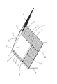
第一実施態様の防水シート10は、図1に示すように、矩形状(長方形状)を為す防水シート本体部11(同図において点P,P,P,Pで囲んだ部分)と、防水シート本体部11の一対の短辺部P,Pのうち一方の短辺部Pに沿って設けられた防水シート筒状部12(同図において点P,P,P,Pで囲んだ部分)とを備えている。防水シート筒状部12には、後掲する図4に示すように、引っ張り用棒材20を通すことができるようになっている。このため、防水シート10を弛みのない張った状態に施工しやすくなることに加えて、引っ張り用棒材20で防水シート10の外縁を施工対象面αに対して押し付けた状態とすることができるようになっている。したがって、施工後の防水シートが風で煽られて浮き上がらないようにすることが可能になる。 As shown in FIG. 1, the tarpaulin 10 of the first embodiment has a rectangular (rectangular) waterproof sheet main body 11 (a portion surrounded by points P 1 , P 2 , P 3 , and P 4 in the figure). a) in a pair of short side portions P 1 waterproof provided along the P 2 sheet tubular portion 12 (FIG of one of the shorter sides P 1 P 2, P 3 P 4 tarpaulin main body portion 11 and a portion surrounded) and at the point P 1, P 2, P 5 , P 6. As shown in FIG. 4 to be described later, the pulling rod 20 can be passed through the waterproof sheet tubular portion 12. Therefore, in addition to facilitating the construction of the waterproof sheet 10 in a stretched state without slack, the outer edge of the waterproof sheet 10 can be pressed against the construction target surface α by the pulling rod 20. It has become like. Therefore, it is possible to prevent the waterproof sheet after construction from being lifted by the wind.

防水シート本体部11及び防水シート筒状部12は、別部材からなるものを、縫着、接着又は溶着等することによって互いに固定したものであってもよいが、第一実施態様の防水シート10では、同一部材(連続した1枚のシート材)で形成したものとなっている。すなわち、矩形状(長方形状)を為す1枚のシート材の縁部付近を、折線P(図1)に沿って折り返すことで、そのシート材の縁部付近にシート材が2重に重なった重合部(図1における点P,P,P,Pで囲んだ部分)を形成し、その重合部で重なったシート材を、重合部の内側の縁部(図1における線分P)に沿って縫着等することで、その重合部が防水シート筒状部12になるようにしている。これにより、防水シート10の部品点数を減らすことが可能となっている。 The waterproof sheet main body 11 and the waterproof sheet tubular portion 12 may be fixed to each other by sewing, adhering, welding, or the like, but the waterproof sheet 10 of the first embodiment. Is formed of the same member (one continuous sheet material). That is, by folding back the vicinity of the edge of one sheet material having a rectangular shape (rectangular shape) along the folding line P 5 P 6 (Fig. 1), the sheet material is doubled near the edge of the sheet material. overlapping polymerized portion (portion surrounded by the points P 1, P 2, P 5 , P 6 in FIG. 1) is formed, the sheet material overlapping at the overlapping portion, the inner edge of the overlapped portion (FIG. 1 By sewing or the like along the line segment P 1 P 2 ) in the above, the overlapping portion becomes the waterproof sheet tubular portion 12. This makes it possible to reduce the number of parts of the waterproof sheet 10.

防水シート本体部11及び防水シート筒状部12を形成するシート材は、防水性を有するのであれば、その種類を特に限定されないが、通常、合成樹脂からなるシート材や、合成樹脂を基材に一体化させたシート材等が用いられる。合成樹脂としては、ポリエチレンやプロピレン等のポリオレフィン、ポリ塩化ビニル、ポリエチレンテレフタレート等のポリエステル、ナイロン等のポリアミド、テトラフルオロエチレン等の熱可塑性樹脂が例示される。これらの合成樹脂は、1種類のみを用いてもよく、2種類以上を併用してもよい。また、合成樹脂を一体化させる基材としては、塩化ビニルフィルム、帆布、塗装用メッシュシート、塩化ビニルターポリンシート、ポリエチレン又はポリプロピレン製ラミクロスシート、不織布等が例示される。防水シート本体部11及び防水シート筒状部12を形成するシート材の厚さは、特に限定されないが、概ね0.1〜0.5mmの範囲内とされる。 The type of the sheet material forming the waterproof sheet main body 11 and the waterproof sheet tubular portion 12 is not particularly limited as long as it has waterproof property, but usually, a sheet material made of synthetic resin or a synthetic resin as a base material is used as a base material. A sheet material or the like integrated with the above is used. Examples of the synthetic resin include polyolefins such as polyethylene and propylene, polyesters such as polyvinyl chloride and polyethylene terephthalate, polyamides such as nylon, and thermoplastic resins such as tetrafluoroethylene. Only one type of these synthetic resins may be used, or two or more types may be used in combination. Examples of the base material on which the synthetic resin is integrated include a vinyl chloride film, canvas, a mesh sheet for painting, a vinyl chloride tarpaulin sheet, a polyethylene or polypropylene lamic cloth sheet, and a non-woven fabric. The thickness of the sheet material forming the waterproof sheet main body 11 and the waterproof sheet tubular portion 12 is not particularly limited, but is generally within the range of 0.1 to 0.5 mm.

防水シート筒状部12は、防水シート本体部11の辺部Pに沿って断続的に設けてもよいが、第一実施態様の防水シート10においては、図1に示すように、辺部Pの全区間に亘って連蔵的に設けている。これにより、防水シート本体部11の辺部Pの全区間を、引っ張り用棒材(図4)で均等に引っ張ることが可能になる。したがって、施工後の防水シート10に弛みやシワ等が形成されにくくすることができる。 The waterproof sheet tubular portion 12 may be provided intermittently along the side portions P 1 P 2 of the waterproof sheet main body portion 11, but in the waterproof sheet 10 of the first embodiment, as shown in FIG. It is provided continuously over the entire section of the sides P 1 and P 2. As a result, the entire section of the side portions P 1 P 2 of the waterproof sheet main body 11 can be evenly pulled by the pulling rod (FIG. 4). Therefore, it is possible to prevent slack and wrinkles from being formed on the waterproof sheet 10 after construction.

防水シート筒状部12の幅(防水シート筒状部12を扁平に押し潰したときの幅。図1における「幅W」を参照。)は、特に限定されない。しかし、防水シート筒状部12の幅Wを狭くしすぎると、防水シート筒状部12に細い引っ張り用棒材20しか通すことができなくなる。また、防水シート筒状部12に引っ張り用棒材20を通しにくくなるおそれもある。このため、防水シート筒状部12の幅Wは、5cm以上とすることが好ましい。防水シート筒状部12の幅Wは、10cm以上とすることがより好ましく、15cm以上とすることがさらに好ましい。 The width of the waterproof sheet tubular portion 12 (the width when the waterproof sheet tubular portion 12 is crushed flat. See “width W 1 ” in FIG. 1) is not particularly limited. However, if the width W 1 of the waterproof sheet tubular portion 12 is made too narrow, only the thin pulling rod 20 can be passed through the waterproof sheet tubular portion 12. In addition, it may be difficult to pass the pulling rod 20 through the tubular portion 12 of the waterproof sheet. Therefore, the width W 1 of the waterproof sheet tubular portion 12 is preferably 5 cm or more. The width W 1 of the waterproof sheet tubular portion 12 is more preferably 10 cm or more, and further preferably 15 cm or more.

ただし、防水シート筒状部12の幅Wを広くしすぎても、あまり意味がない。このため、防水シート筒状部12の幅Wは、通常、50cm以下とされる。防水シート筒状部12の幅Wは、40cm以下とすることが好ましく、30cm以下とすることがより好ましい。第一実施態様の防水シート10においては、防水シート筒状部12の幅Wを、25cmとしている。これにより、建築現場等で余った角材(建築用の角材は、その断面における一辺の長さが20〜100mmの範囲であるものが多い。)を、引っ張り用棒材20として使用することが可能になる。 However, it does not make much sense to make the width W 1 of the waterproof sheet tubular portion 12 too wide. Therefore, the width W 1 of the waterproof sheet tubular portion 12 is usually 50 cm or less. The width W 1 of the waterproof sheet tubular portion 12 is preferably 40 cm or less, and more preferably 30 cm or less. In the waterproof sheet 10 of the first embodiment, the width W 1 of the waterproof sheet tubular portion 12 is 25 cm. As a result, it is possible to use the surplus square timber at a construction site or the like (many square timbers for construction have a side length in the range of 20 to 100 mm in the cross section) as the pulling bar 20. become.

防水シート本体部11の各辺部の長さL,L(図1)は、特に限定されない。しかし、防水シート本体部11の各辺部の長さL,Lを短くしすぎると、防水シート10の面積が小さくなり、施工対象面が広い場合に多数枚の防水シート10を施工する必要が生じる。このため、防水シート本体部11の各辺部の長さL,Lは、通常、0.5m以上とされる。防水シート本体部11の各辺部の長さL,Lは、1m以上とすることが好ましく、1.5m以上とすることがより好ましい。特に、第一実施態様の防水シート10のように、防水シート本体部11が矩形状(長方形状)を為し、防水シート本体部11が短辺部P,Pと長辺部P,Pとを有する場合には、防水シート本体部11の長辺部の長さLは、2m以上とすることが好ましく、3m以上とすることがより好ましい。 The lengths L 1 and L 2 (FIG. 1) of each side of the waterproof sheet main body 11 are not particularly limited. However, if the lengths L 1 and L 2 of each side of the waterproof sheet main body 11 are made too short, the area of the waterproof sheet 10 becomes small, and when the surface to be constructed is wide, a large number of waterproof sheets 10 are constructed. Need arises. Therefore, the lengths L 1 and L 2 of each side of the waterproof sheet main body 11 are usually set to 0.5 m or more. The lengths L 1 and L 2 of each side of the waterproof sheet main body 11 are preferably 1 m or more, and more preferably 1.5 m or more. In particular, like the tarpaulin 10 of the first embodiment, the tarpaulin main body 11 has a rectangular shape (rectangular shape), and the tarpaulin main body 11 has a short side portion P 1 P 2 , P 3 P 4 and a long length. When the side portions P 2 P 3 and P 4 P 1 are provided, the length L 1 of the long side portion of the tarpaulin main body 11 is preferably 2 m or more, and more preferably 3 m or more. ..

ただし、防水シート本体部11の各辺部の長さL,Lを長くしすぎると、防水シート10の面積が大きくなりすぎて、防水シート10の施工性が低下する。このため、防水シート本体部11の各辺部の長さL,Lは、通常、15m以下とされる。防水シート本体部11の各辺部の長さL,Lは、10m以下とすることが好ましく、7m以下とすることがより好ましい。特に、第一実施態様の防水シート10のように、防水シート本体部11が矩形状(長方形状)を為し、防水シート本体部11が短辺部P,Pと長辺部P,Pとを有する場合には、防水シート本体部11の短辺部の長さLは、5m以下とすることが好ましく、3m以下とすることがより好ましい。第一実施態様の防水シート10では、長辺部の長さLが5mで短辺部の長さLが1.5mのものと、長辺部の長さLが5mで短辺部の長さLが3mのものとの2種類を用意している。 However, if the lengths L 1 and L 2 of each side of the waterproof sheet main body 11 are made too long, the area of the waterproof sheet 10 becomes too large, and the workability of the waterproof sheet 10 deteriorates. Therefore, the lengths L 1 and L 2 of each side of the waterproof sheet main body 11 are usually set to 15 m or less. The lengths L 1 and L 2 of each side of the waterproof sheet main body 11 are preferably 10 m or less, and more preferably 7 m or less. In particular, like the tarpaulin 10 of the first embodiment, the tarpaulin main body 11 has a rectangular shape (rectangular shape), and the tarpaulin main body 11 has a short side portion P 1 P 2 , P 3 P 4 and a long length. When the side portions P 2 P 3 and P 4 P 1 are provided, the length L 2 of the short side portion of the tarpaulin main body 11 is preferably 5 m or less, and more preferably 3 m or less. .. In the tarpaulin 10 of the first embodiment, the length L 1 of the long side portion is 5 m and the length L 2 of the short side portion is 1.5 m, and the length L 1 of the long side portion is 5 m and the short side. Two types are available, one with a part length L 2 of 3 m.

防水シート本体部11の辺部P,P,P(防水シート筒状部12が設けられていない辺部)に沿った箇所には、複数の鳩目穴13が、所定間隔で形成されている。これらの鳩目穴13は、防水シート本体部11を表裏に貫通した状態に設けられている。これらの鳩目穴13には、ロープやワイヤ等を通したり、ペグを打ち込むことができる。これにより、防水シート本体部11の外縁における、防水シート筒状部12が設けられていない箇所(引っ張り用棒材20が通されない箇所)も、外方に引っ張ったり、施工対象面に押し付けた状態とすることができる。これにより、防水シート10を、その施工態様等に応じて、より適切な状態で施工することが可能になる。 A plurality of eyelet holes 13 are formed along the sides P 2 P 3 , P 3 P 4 , P 4 P 1 (the side where the waterproof sheet tubular portion 12 is not provided) of the waterproof sheet main body 11. , Are formed at predetermined intervals. These eyelet holes 13 are provided so as to penetrate the waterproof sheet main body 11 on the front and back sides. A rope, a wire, or the like can be passed through these eyelet holes 13 or a peg can be driven into them. As a result, the outer edge of the waterproof sheet main body 11 where the waterproof sheet tubular portion 12 is not provided (the portion through which the pulling rod 20 is not passed) is also pulled outward or pressed against the construction target surface. Can be. This makes it possible to construct the waterproof sheet 10 in a more appropriate state according to the construction mode and the like.

鳩目穴13を設けるピッチは、特に限定されないが、通常、20〜150cm、好ましくは、30〜120cmとされる。第一実施態様の防水シート10においては、防水シート本体部11の長辺部P,Pに沿った箇所には、約100cmのピッチで鳩目穴13を設けており、防水シート本体部11の短辺部Pに沿った箇所には、約37cmのピッチで鳩目穴13を設けている。 The pitch at which the eyelet holes 13 are provided is not particularly limited, but is usually 20 to 150 cm, preferably 30 to 120 cm. In the waterproof sheet 10 of the first embodiment, eyelet holes 13 are provided at a pitch of about 100 cm at locations along the long side portions P 2 P 3 , P 4 P 1 of the waterproof sheet main body 11, and are waterproof. Eyelet holes 13 are provided at a pitch of about 37 cm at locations along the short side portions P 3 P 4 of the seat body portion 11.

第一実施態様の防水シート10においては、防水シート本体部11における防水シート筒状部12が設けられていない辺部Pに沿って帯状片14(図1において点Q,Q,Q,Qで囲んだ部分)を取り付けている。この帯状片14は、防水シート本体部11の外縁(辺部P)付近に重なった状態となっている。帯状片14における長手方向に沿った一対の縁部(基端縁Q及び先端縁Q)のうち一方の縁部(基端縁Q)に沿った箇所は、防水シート本体部11に縫着されている。また、帯状片14の他方の縁部(先端縁Q)は、防水シート本体部11の外縁(辺部P)よりも外方に突出している。 In the waterproof sheet 10 of the first embodiment, the strip-shaped piece 14 (points Q 1 and Q 2 in FIG. 1) is provided along the side portion P 1 P 4 in which the waterproof sheet tubular portion 12 is not provided in the waterproof sheet main body portion 11. , I attach the part) surrounded by a Q 3, Q 4. The strip-shaped piece 14 is in a state of being overlapped in the vicinity of the outer edge (side portion P 1 P 4) of the waterproof sheet main body portion 11. The portion of the strip 14 along one of the pair of edges (base edge Q 2 Q 3 and tip edge Q 1 Q 4 ) along the longitudinal direction is located along one edge (base edge Q 2 Q 3 ). It is sewn on the waterproof sheet main body 11. Further, the other edge portion (tip edge Q 1 Q 4 ) of the strip-shaped piece 14 protrudes outward from the outer edge portion (side portion P 1 P 4) of the waterproof sheet main body portion 11.

この帯状片14は、オーバーラップ部材として利用することができる。すなわち、複数枚の防水シート10を並べて施工する場合には、通常、隣り合う防水シート10は、引っ張り用棒材20が挿入されない縁部(防水シート筒状部12が設けられていない縁部)同士が重なるように配していく(一の防水シート10の縁部Pに、当該一の防水シート10の隣に配される他の防水シート10の縁部Pが重なるように配していく)が、このときに、帯状片14を隣に配される防水シート10の縁部にオーバーラップさせることができる。したがって、隣り合う防水シート10の重なり代を広く確保し、隣り合う防水シート10の境界部分から雨水等が侵入しないようにすることができる。加えて、防水シート10における、帯状片14が設けられた縁部Pに上記の鳩目穴13が形成されている場合には、その鳩目穴13を帯状片14で覆って、その鳩目穴13から雨水等が侵入しにくくすることもできる。帯状片14で覆われる鳩目穴13は、鳩目部材を用いない空打ち仕様としてもよい。 The strip-shaped piece 14 can be used as an overlapping member. That is, when a plurality of tarpaulins 10 are installed side by side, the adjacent tarpaulins 10 are usually edges where the pulling rod 20 is not inserted (the edges where the tarpaulin 12 is not provided). Arrange them so that they overlap each other (the edge P 2 P 3 of one tarpaulin 10 is overlapped with the edges P 1 P 4 of another tarpaulin 10 arranged next to the one tarpaulin 10. However, at this time, the strip-shaped piece 14 can be overlapped with the edge of the waterproof sheet 10 arranged next to it. Therefore, it is possible to secure a wide overlap margin between the adjacent waterproof sheets 10 and prevent rainwater or the like from entering from the boundary portion of the adjacent waterproof sheets 10. In addition, when the eyelet hole 13 is formed in the edge portion P 1 P 4 provided with the band-shaped piece 14 in the waterproof sheet 10, the eyelet hole 13 is covered with the band-shaped piece 14 and the eyelet eye is formed. It is also possible to prevent rainwater or the like from entering through the hole 13. The eyelet hole 13 covered with the strip-shaped piece 14 may be a blank beating specification that does not use the eyelet member.

帯状片14は、防水シート本体部11の縁部Pに沿って断続的に設けてもよいが、第一実施態様の防水シート10においては、図1に示すように、縁部Pの全区間に亘って連蔵的に設けている。これにより、隣り合う防水シート10の境界部分における略全体を帯状片14で覆い、その境界部分から雨水等がより侵入しにくくすることができる。 The strip 14 may be provided intermittently along the edge P 1 P 4 of the waterproof sheet main body 11, but in the waterproof sheet 10 of the first embodiment, as shown in FIG. 1, the edge P may be provided. It is provided communicating built manner over the entire interval of 1 P 4. As a result, it is possible to cover substantially the entire boundary portion of the adjacent waterproof sheets 10 with the strip-shaped piece 14, and make it more difficult for rainwater or the like to enter from the boundary portion.

帯状片14の突出幅(帯状片14における、防水シート本体部11の縁部Pから外方に突き出る部分の幅。図1における「幅W」を参照。)は、特に限定されない。しかし、帯状片14の突出幅Wを狭くしすぎると、隣り合う防水シート10の重なり代を広く確保しにくくなる。このため、帯状片14の突出幅Wは、1cm以上とすることが好ましい。帯状片14の突出幅Wは、3cm以上とすることが好ましく、5cm以上とすることがより好ましい。ただし、帯状片14の突出幅Wを広くしすぎると、帯状片14が風でバタツキやすくなる。このため、帯状片14の突出幅Wは、通常、20cm以下とされる。帯状片14の突出幅Wは、15cm以下とすることが好ましく、10cm以下とすることがより好ましい。第一実施態様の防水シート10において、帯状片14の突出幅Wは、約5cmとしている。 The protruding width of the strip-shaped piece 14 (the width of the portion of the strip-shaped piece 14 that protrudes outward from the edge P 1 P 4 of the waterproof sheet main body 11; see "width W 2 " in FIG. 1) is not particularly limited. .. However, if the protruding width W 2 of the strip-shaped piece 14 is made too narrow, it becomes difficult to secure a wide overlap margin between the adjacent waterproof sheets 10. Therefore, the protruding width W 2 of the strip-shaped piece 14 is preferably 1 cm or more. The protruding width W 2 of the strip 14 is preferably 3 cm or more, and more preferably 5 cm or more. However, if the protruding width W 2 of the strip-shaped piece 14 is made too wide, the strip-shaped piece 14 tends to flutter due to the wind. Therefore, the protruding width W 2 of the strip-shaped piece 14 is usually 20 cm or less. The protruding width W 2 of the strip 14 is preferably 15 cm or less, and more preferably 10 cm or less. In the waterproof sheet 10 of the first embodiment, the protruding width W 2 of the strip-shaped piece 14 is about 5 cm.

また、第一実施態様の防水シート10においては、紐通し部15を、防水シート本体部11の片面に設けている。以下においては、防水シート本体部11における、紐通し部15が設けられた側の面を「オモテ面」と呼び、それとは反対側の面を「ウラ面」と呼ぶことがある。紐通し部15は、防水シート本体部11の長手方向中途部分における左側部分及び右側部分の2箇所に設けている。図1に示した例では、三角状の生地に鳩目穴をあけた部材(いわゆるペケット)を、紐通し部15として設けている。この紐通し部15には、後掲する図5に示すように、支持用紐材30を通すことができる。 Further, in the waterproof sheet 10 of the first embodiment, the stringing portion 15 is provided on one side of the waterproof sheet main body portion 11. In the following, the surface of the waterproof sheet main body 11 on the side where the stringing portion 15 is provided may be referred to as a "front surface", and the surface on the opposite side thereof may be referred to as a "back surface". The stringing portions 15 are provided at two locations, a left side portion and a right side portion, in the middle portion in the longitudinal direction of the waterproof sheet main body portion 11. In the example shown in FIG. 1, a member (so-called pecket) in which a dovetail hole is formed in a triangular cloth is provided as a string threading portion 15. As shown in FIG. 5 to be described later, the support string member 30 can be passed through the string threading portion 15.

これにより、防水シート10の長手方向中途部分を支持用紐材30で支持することができる。したがって、防水シート10の長手方向中途部分が風等で浮き上がらないようにすることができる。後述するように、防水シート10の上側に、土嚢や水嚢等の嚢袋を置く場合には、その嚢袋を、支持用紐材30の端部に結んで嚢袋の位置がズレないようにすることもできる。その際には、紐通し部15を、嚢袋を設置する箇所を支持するガイドとして利用することもできる。また、後掲する図5に示すように、防水シート10でタープ50を形成する場合には、防水シート10の長手方向中途部分が下側に沈み込まないようにすることもできる。
As a result, the middle portion of the waterproof sheet 10 in the longitudinal direction can be supported by the support string member 30. Therefore, it is possible to prevent the middle portion of the waterproof sheet 10 in the longitudinal direction from rising due to wind or the like. As will be described later, when a bag such as a sandbag or a water bag is placed on the upper side of the tarpaulin 10, the bag is tied to the end of the support string 30 so that the position of the bag does not shift. It can also be. In that case, the stringing portion 15 can also be used as a guide for supporting the place where the sac is installed. Further, as shown in FIG. 5 described later, when the tarp 50 is formed by the waterproof sheet 10, it is possible to prevent the middle portion of the waterproof sheet 10 in the longitudinal direction from sinking downward.

2.第二実施態様の防水シート
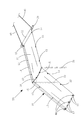
続いて、第二実施態様の防水シートについて説明する。第二実施態様の防水シートについては、上述した第一実施態様の防水シート10と異なる構成に絞って説明する。第二実施態様の防水シート10で特に言及しない構成は、第一実施態様の防水シート10と同様の構成を採用することができる。図2は、本発明に係る第一実施態様の防水シート10を示した斜視図である。
2. The waterproof sheet of the second embodiment Next, the waterproof sheet of the second embodiment will be described. The waterproof sheet of the second embodiment will be described focusing on a configuration different from that of the waterproof sheet 10 of the first embodiment described above. As the configuration not particularly mentioned in the waterproof sheet 10 of the second embodiment, the same configuration as the waterproof sheet 10 of the first embodiment can be adopted. FIG. 2 is a perspective view showing the waterproof sheet 10 of the first embodiment according to the present invention.

第一実施態様の防水シート10は、図1に示すように、防水シート本体部11の一対の短辺部P,Pのうち、一方の短辺部Pに沿った箇所には、防水シート筒状部12が設けられていたが、他方の短辺部Pに沿った箇所には、防水シート筒状部12が設けられておらず、鳩目穴13が設けられていた。これに対し、第二実施態様の防水シート10は、図2に示すように、防水シート本体部11における一方の短辺部Pに沿った箇所だけでなく、他方の短辺部Pに沿った箇所にも、防水シート筒状部12が設けられている。防水シート本体部11の短辺部Pに沿った箇所には、鳩目穴13を設けていない。 Tarpaulin 10 of the first embodiment, as shown in FIG. 1, of the waterproof pair of short sides of the seat body 11 portion P 1 P 2, P 3 P 4, in one short side portion P 1 P 2 The waterproof sheet tubular portion 12 was provided along the portion, but the waterproof sheet tubular portion 12 was not provided at the portion along the other short side portion P 3 P 4, and the eyelet hole was provided. 13 was provided. On the other hand, in the waterproof sheet 10 of the second embodiment, as shown in FIG. 2 , not only the portion of the waterproof sheet main body 11 along one short side portion P 1 P 2 but also the other short side portion P also point along the 3 P 4, tarpaulins tubular portion 12 is provided. The eyelet hole 13 is not provided at a position along the short side portion P 3 P 4 of the waterproof sheet main body portion 11.

これにより、後掲する図4に示すように、双方の防水シート筒状部12に引っ張り用棒材20をそれぞれ挿入し、これらの引っ張り用棒材20を、互いに離反する向きに引っ張ることによって、防水シート10の全体を張った状態に施工しやすくなる。また、仮に、防水シート本体部11の長辺部P,Pに防水シート筒状部12を設け、その防水シート筒状部12に引っ張り用棒材20を挿入した場合には、後掲する図4に示す屋根のように、防水シート10の施工対象面αに突き出た部分(屋根の棟等)がある場合に、引っ張り用棒材20が邪魔になって、防水シート10を施工対象面αに沿わせにくくなるところ、図2に示した第二実施態様の防水シート10のように、防水シート本体部11の短辺部P,Pに設けた防水シート筒状部12に引っ張り用棒材20を挿入することで、引っ張り用棒材20が邪魔にならない状態で、防水シート10を施工対象面αに沿わせやすくなる。 As a result, as shown in FIG. 4 to be described later, the pulling rods 20 are inserted into both of the waterproof sheet tubular portions 12, and the pulling rods 20 are pulled in directions away from each other. It becomes easy to install the waterproof sheet 10 in a stretched state. Further, if a tarpaulin tubular portion 12 is provided on the long side portions P 2 P 3 , P 4 P 1 of the tarpaulin main body 11, and the pulling rod 20 is inserted into the tarpaulin tubular portion 12. When there is a protruding portion (roof ridge, etc.) on the construction target surface α of the tarpaulin 10 as in the roof shown in FIG. 4 described later, the pulling rod 20 becomes an obstacle and the tarpaulin 20 is used. Where it becomes difficult to align 10 with the construction target surface α, it is provided on the short side portions P 1 P 2 and P 3 P 4 of the tarpaulin main body 11 as in the tarpaulin 10 of the second embodiment shown in FIG. By inserting the pulling rod 20 into the tubular portion 12 of the tarpaulin, the tarpaulin 10 can be easily aligned with the construction target surface α in a state where the pulling rod 20 does not get in the way.

また、第一実施態様の防水シート10では、図1に示すように、防水シート本体部11のオモテ面側における2箇所に、紐通し部15としてペケットを設けていた。これに対し、第二実施態様の防水シート10では、図2に示すように、防水シート本体部11のオモテ面側における6箇所に、棒通し部16としてループを設けている。棒通し部16は、防水シート本体部11をその長辺部P,Pに略4等分する箇所に2個ずつ設けている。上記の棒通し部16(ループ)に図示省略の支持用棒材を通すことで、防水シート本体部11の長手方向中途部分で防水シート本体部11を短手方向にわたって支持することが可能となっている。
Further, in the waterproof sheet 10 of the first embodiment, as shown in FIG. 1, peckets are provided as stringing portions 15 at two places on the front surface side of the waterproof sheet main body portion 11. On the other hand, in the waterproof sheet 10 of the second embodiment, as shown in FIG. 2, loops are provided as rod passing portions 16 at six locations on the front surface side of the waterproof sheet main body portion 11. The bar threading portion 16 is provided with two waterproof sheet main body portions 11 at locations where the long side portions P 2 P 3 and P 4 P 1 are substantially divided into four equal parts. By passing a support rod material (not shown) through the rod threading portion 16 (loop), it is possible to support the waterproof sheet main body 11 in the middle portion in the longitudinal direction of the waterproof sheet main body 11 over the short direction. ing.

3.第三実施態様の防水シート
続いて、第三実施態様の防水シートについて説明する。第三実施態様の防水シートについては、上述した第二実施態様の防水シート10と異なる構成に絞って説明する。第三実施態様の防水シート10で言及しない構成は、第二実施態様の防水シート10と同様の構成を採用することができる。図3は、本発明に係る第一実施態様の防水シート10を示した斜視図である。
3. 3. The waterproof sheet of the third embodiment Next, the waterproof sheet of the third embodiment will be described. The waterproof sheet of the third embodiment will be described focusing on a configuration different from that of the waterproof sheet 10 of the second embodiment described above. As the configuration not mentioned in the waterproof sheet 10 of the third embodiment, the same configuration as the waterproof sheet 10 of the second embodiment can be adopted. FIG. 3 is a perspective view showing the waterproof sheet 10 of the first embodiment according to the present invention.

第二実施態様の防水シート10では、図2に示すように、棒通し部16を、防水シート本体部11とは別個に形成された部材(帯状の生地)を防水シート本体部11に対して固定(縫着)することによって設けていた。これに対し、第三実施態様の防水シート10では、図3に示すように、防水シート本体部11における特定区間をループ状にたくり、そのループ状の部分の付根を縫着することによって、棒通し部16を形成している。これにより、防水シート本体部11の一方の側縁から他方の側縁にわたって棒通し部16を連続的に形成することができる。また、棒通し部16を強靭に形成して破損しにくくすることも可能となっている。
In the waterproof sheet 10 of the second embodiment, as shown in FIG. 2, the rod threading portion 16 is provided with a member (strip-shaped cloth) formed separately from the waterproof sheet main body 11 with respect to the waterproof sheet main body 11. It was provided by fixing (sewn). On the other hand, in the waterproof sheet 10 of the third embodiment, as shown in FIG. 3, a specific section of the waterproof sheet main body 11 is formed in a loop shape, and the root of the loop-shaped portion is sewn to form a rod. A through portion 16 is formed. As a result, the bar threading portion 16 can be continuously formed from one side edge of the waterproof sheet main body 11 to the other side edge. Further, it is also possible to form the rod threading portion 16 tough to prevent it from being damaged.

4.本発明の防水シートの施工例
本発明の防水シート10の施工例について説明する。図4は、本発明の防水シート10を建物の屋根αの上に施工した状態を示した斜視図である。図4の防水シート10は、上記の第二実施態様の防水シート10(図2)に該当するもの(防水シート本体部11の一対の短辺部に防水シート筒状部12が設けられたもの)となっている。本発明の防水シート10は、図4に示すように、屋根αの棟に跨った状態で施工することができる。本発明の防水シート10を屋根αに施工する場合には、防水シート10は、通常、オモテ面(紐通し部15又は棒通し部16が設けられた側の面)が上側を向く状態で張られる。図4では、図2における棒通し部16を省略している。
4. Construction example of the waterproof sheet of the present invention A construction example of the waterproof sheet 10 of the present invention will be described. FIG. 4 is a perspective view showing a state in which the waterproof sheet 10 of the present invention is installed on the roof α of the building. The waterproof sheet 10 of FIG. 4 corresponds to the waterproof sheet 10 (FIG. 2) of the second embodiment (the waterproof sheet tubular portion 12 is provided on a pair of short sides of the waterproof sheet main body 11). ). As shown in FIG. 4, the waterproof sheet 10 of the present invention can be installed while straddling the roof α ridge. When the waterproof sheet 10 of the present invention is applied to the roof α, the waterproof sheet 10 is usually stretched with the front surface (the surface on which the string threading portion 15 or the bar threading portion 16 is provided) faces upward. Be done. In FIG. 4, the rod threading portion 16 in FIG. 2 is omitted.

このとき、それぞれの防水シート10に引っ張り用棒材20を挿入し、引っ張り用棒材20における、防水シート筒状部12の両端から突き出た部分に引っ張り用紐40を結び、その引っ張り用紐40の他端側を屋根αの下側に引っ張ることによって、防水シート10を屋根αに沿った状態で張ることができる。防水シート10の短辺部は、引っ張り用棒材20によって屋根αに押し付けられた状態となる。また、防水シート10の長辺部も、屋根αに押し付けられた状態となる。このため、防水シート10と屋根αとの間に風が入り込まないようにして、防水シート10が風に煽られて浮き上がらないようにすることができる。 At this time, the pulling rod 20 is inserted into each of the waterproof sheets 10, and the pulling string 40 is tied to the portions of the pulling rod 20 protruding from both ends of the tubular portion 12 of the waterproof sheet, and the pulling string 40 is tied. By pulling the other end side of the roof α to the lower side of the roof α, the waterproof sheet 10 can be stretched along the roof α. The short side portion of the waterproof sheet 10 is in a state of being pressed against the roof α by the pulling rod 20. Further, the long side portion of the waterproof sheet 10 is also in a state of being pressed against the roof α. Therefore, it is possible to prevent the wind from entering between the waterproof sheet 10 and the roof α so that the waterproof sheet 10 is not lifted by the wind.

防水シート10に設けられた鳩目穴13には、図示省略の紐等を結びつけることができる。その紐を屋根αの下側に引っ張れば、防水シート10の長辺部を、屋根αに対してさらに押し付けられた状態とすることができ、防水シート10をより浮き上がりにくくすることができる。また、鳩目穴13に通した上記の紐は、防水シート10の隣に配置する別の防水シート10(図示省略)の鳩目穴13に結び付けることもできる。これにより、隣り合う防水シート10を連結することができる。 A string or the like (not shown) can be tied to the eyelet hole 13 provided in the waterproof sheet 10. By pulling the string to the lower side of the roof α, the long side portion of the waterproof sheet 10 can be further pressed against the roof α, and the waterproof sheet 10 can be made more difficult to lift. Further, the above-mentioned string passed through the eyelet hole 13 can be tied to the eyelet hole 13 of another waterproof sheet 10 (not shown) arranged next to the waterproof sheet 10. As a result, the adjacent waterproof sheets 10 can be connected.

また、防水シート10における棒通し部16(図2を参照。)には、図示省略の支持用棒材を通すこともできる。これにより、支持用棒材で、防水シート10の長手方向中途部分を、防水シート10の短手方向にわたって支持することができる。棒通し部16に通した支持用棒材は、錘としても機能する。このため、防水シート10を、支持用棒材を通した部分で屋根αに押し付けることも可能になる。棒通し部16の代わりに紐通し部15(図1を参照。)を設けた場合には、その紐通し部15に支持用紐材を通すことができる。この支持用紐材の両端には、土嚢や水嚢等の嚢袋を連結し、その嚢袋を防水シート10の上側に置くことで、その箇所でも防水シート10を押し付けることが可能になる。また、嚢袋の位置ズレや落下を防止することもできる。 Further, a support rod material (not shown) can be passed through the rod threading portion 16 (see FIG. 2) of the waterproof sheet 10. As a result, the supporting rod can support the middle portion of the waterproof sheet 10 in the longitudinal direction over the short side of the waterproof sheet 10. The supporting rod material passed through the rod threading portion 16 also functions as a weight. Therefore, the waterproof sheet 10 can be pressed against the roof α at the portion through which the supporting rod material is passed. When a string threading portion 15 (see FIG. 1) is provided instead of the bar threading portion 16, the supporting string material can be passed through the string threading portion 15. By connecting a sac such as a sandbag or a water sac to both ends of the supporting string material and placing the sac on the upper side of the waterproof sheet 10, the waterproof sheet 10 can be pressed at that location as well. In addition, it is possible to prevent the bag from being displaced or dropped.

図4に示した施工態様は、台風等の災害で屋根αが破損したときの応急処置として有効である。また、家屋の建設時において、屋根αに瓦等の屋根材が載るまでの間、家屋を風雨等から保護する場合にも有効である。 The construction mode shown in FIG. 4 is effective as an emergency measure when the roof α is damaged due to a disaster such as a typhoon. It is also effective in protecting the house from wind and rain until the roofing material such as roof tiles is placed on the roof α at the time of construction of the house.

図5は、本発明の防水シート10でタープを施工した状態を示した斜視図である。キャンプ等の野外活動を行う際には、日除けや雨除けのために、図5に示すようなタープ50を設置したい場合がある。また、台風等の災害によって家屋が被害を受け、家屋やその周辺に、日除けや雨除けできるスペースを確保したいときにも、図5に示すようなタープ50を設置したい場合がある。本発明の防水シート10は、このようなタープ50を設置する場合にも有効に使用することができる。図5の防水シート10は、上記の第一実施態様の防水シート10(図1)に該当するもの(防水シート本体部11の一方の短辺部に防水シート筒状部12が設けられたもの)となっている。 FIG. 5 is a perspective view showing a state in which the tarp is applied to the waterproof sheet 10 of the present invention. When conducting outdoor activities such as camping, it may be desirable to install a tarp 50 as shown in FIG. 5 for awning and rain protection. Further, when a house is damaged by a disaster such as a typhoon and it is desired to secure a space for awning or rain in the house or its surroundings, it may be desired to install a tarp 50 as shown in FIG. The waterproof sheet 10 of the present invention can be effectively used even when such a tarp 50 is installed. The waterproof sheet 10 of FIG. 5 corresponds to the waterproof sheet 10 (FIG. 1) of the first embodiment (the waterproof sheet tubular portion 12 is provided on one short side of the waterproof sheet main body 11). ).

図5に示したタープ50は、防水シート10の一方の短辺部に設けられた防水シート筒状部12に引っ張り用棒材20を挿通し、その引っ張り用棒材20における、防水シート筒状部12の両端から突き出た部分に引っ張り用紐40を結び、その引っ張り用紐40の他端側を図示省略の樹木等に結び付けることによって施工している。防水シート10の他方の短辺部は、その短辺部に沿って設けた鳩目穴13にペグ60を打ち込むことによって、地面に固定している。これにより、防水シート10を長手方向に引っ張った状態とすることができる。 In the tarp 50 shown in FIG. 5, the pulling rod 20 is inserted into the waterproof sheet tubular portion 12 provided on one short side of the waterproof sheet 10, and the waterproof sheet tubular portion in the pulling rod 20 is inserted. The construction is carried out by tying a pulling string 40 to a portion protruding from both ends of the portion 12, and tying the other end side of the pulling string 40 to a tree or the like (not shown). The other short side portion of the waterproof sheet 10 is fixed to the ground by driving a peg 60 into the eyelet hole 13 provided along the short side portion. As a result, the waterproof sheet 10 can be pulled in the longitudinal direction.

また、防水シート10における長手方向中間部は、一対のポール70によって持ち上げた状態としている。一対のポール70の上端部には、支持用紐材30を架け渡している。この支持用紐材30は、防水シート10の下側に通しており、防水シート本体部11に設けた紐通し部15(ペケット)に挿通している。これにより、防水シート10の長手方向中途部分を支持用紐材30で支持し、防水シート10の長手方向中途部分が下側に沈み込まないようにすることができる。 Further, the intermediate portion in the longitudinal direction of the waterproof sheet 10 is in a state of being lifted by a pair of poles 70. A support string member 30 is bridged over the upper ends of the pair of poles 70. The supporting string material 30 is passed through the lower side of the waterproof sheet 10 and is inserted into the string threading portion 15 (pecket) provided in the waterproof sheet main body portion 11. As a result, the halfway portion in the longitudinal direction of the waterproof sheet 10 can be supported by the support string member 30, and the halfway portion in the longitudinal direction of the waterproof sheet 10 can be prevented from sinking downward.

ここで、一対のポール70の上端部に、支持用紐材30の代わりに棒状のもの(支持用棒材)を架け渡すと、防水シート10の長手方向中途部分が下側に沈み込まないようにさらにしっかりと支持することができる。しかし、支持用棒材は、紐通し部15(ペケット)に通すことができない。このため、支持用棒材を用いる場合には、紐通し部15(ペケット)の代わりに、図2に示す棒通し部16(ループ)を設けるとよい。
Here, if a rod-shaped material (supporting rod material) is hung over the upper ends of the pair of poles 70 instead of the supporting string material 30, the middle portion in the longitudinal direction of the waterproof sheet 10 will not sink downward. Can be supported even more firmly. However, the support rod cannot be passed through the string threading portion 15 (pecket). Therefore, when the support rod material is used, it is preferable to provide the rod threading portion 16 (loop) shown in FIG. 2 instead of the string threading portion 15 (pecket).

5.第四実施態様の防水シート
続いて、第四実施態様の防水シートについて説明する。第四実施態様の防水シートについては、上述した実施態様(第一実施態様から第三実施態様まで)の防水シート10と異なる構成に絞って説明する。第四実施態様の防水シートで言及しない構成は、他の実施態様の防水シート10と同様の構成を採用することができる。図6は、本発明に係る第四実施態様の防水シート10Aを示した斜視図である。図6(a)は、防水シート10Aのオモテ面を、図6(b)は、防水シート10Aのウラ面をそれぞれ示している。図7は、本発明に係る第四実施態様の防水シート10Aを建物の屋根αの上に施工した状態を屋根αの側方から見た状態を示した図である。
5. The waterproof sheet of the fourth embodiment Next, the waterproof sheet of the fourth embodiment will be described. The waterproof sheet of the fourth embodiment will be described focusing on a configuration different from that of the waterproof sheet 10 of the above-described embodiment (from the first embodiment to the third embodiment). As the configuration not mentioned in the waterproof sheet of the fourth embodiment, the same configuration as the waterproof sheet 10 of the other embodiment can be adopted. FIG. 6 is a perspective view showing the waterproof sheet 10A of the fourth embodiment according to the present invention. FIG. 6A shows the front surface of the waterproof sheet 10A, and FIG. 6B shows the back surface of the waterproof sheet 10A. FIG. 7 is a view showing a state in which the waterproof sheet 10A of the fourth embodiment according to the present invention is installed on the roof α of the building as viewed from the side of the roof α.

上述した実施態様の防水シート10(図1〜3)では、防水シート本体部11における、防水シート筒状部12に垂直な方向の長さL(以下においては、「縦の長さL」と表記する。)が、筒状シート筒状部12に平行な方向の長さL(以下においては、「横の長さL」と表記する。)よりも長くなっていた。これに対し、第四実施態様の防水シート10Aでは、図6に示すように、防水シート本体部11の横の長さLが、縦の長さLよりも長くなっている。具体的には、縦の長さLが約1.7mmであるのに対し、横の長さLが約2.5mとなっている。このため、第四実施態様の防水シート10Aは、屋根αの横方向(棟に平行な方向)に効率的に施工できるものとなっている。 In the waterproof sheet 10 (FIGS. 1 to 3) of the above-described embodiment, the length L 1 of the waterproof sheet main body 11 in the direction perpendicular to the waterproof sheet tubular portion 12 (hereinafter, “vertical length L 1”. ”) Was longer than the length L 2 in the direction parallel to the tubular sheet tubular portion 12 (hereinafter, referred to as“ horizontal length L 1 ”). On the other hand, in the waterproof sheet 10A of the fourth embodiment, as shown in FIG. 6, the horizontal length L 2 of the waterproof sheet main body 11 is longer than the vertical length L 1. Specifically, the vertical length L 1 is about 1.7 mm, while the horizontal length L 2 is about 2.5 m. Therefore, the waterproof sheet 10A of the fourth embodiment can be efficiently installed in the lateral direction (direction parallel to the ridge) of the roof α.

第四実施態様の防水シート10Aは、図7に示すように、その長手方向(縦方向)中間部が屋根αの棟に重なるように施工される。防水シート10Aの長手方向(縦方向)両端部に設けられた一対の防水シート筒状部12には、引っ張り用棒材20が挿入され、その引っ張り用棒材20は、それに連結された引っ張り用紐40で屋根αの下側に引っ張られる。これにより、防水シート10Aを屋根αに密着した状態で張り、防水シート10Aの浮き上がりを防止することができる。第四実施態様の防水シート10Aは、屋根αの棟付近を保護するものとして好適なものとなっている。
As shown in FIG. 7, the waterproof sheet 10A of the fourth embodiment is constructed so that the intermediate portion in the longitudinal direction (longitudinal direction) overlaps the ridge of the roof α. A pulling rod 20 is inserted into a pair of waterproof sheet tubular portions 12 provided at both ends of the waterproof sheet 10A in the longitudinal direction (longitudinal direction), and the pulling rod 20 is connected to the pair for pulling. It is pulled under the roof α by the string 40. As a result, the waterproof sheet 10A can be stretched in close contact with the roof α to prevent the waterproof sheet 10A from rising. The waterproof sheet 10A of the fourth embodiment is suitable for protecting the vicinity of the roof α ridge.

6.第五実施態様及び第六実施態様の防水シート
続いて、第五実施態様の防水シート及び第六実施態様の防水シートについて説明する。第五実施態様の防水シート及び第六実施態様の防水シートについては、上述した実施態様(第一実施態様から第四実施態様まで)の防水シート10と異なる構成に絞って説明する。第五実施態様の防水シート及び第六実施態様の防水シートで言及しない構成は、他の実施態様の防水シート10と同様の構成を採用することができる。図8は、本発明に係る第五実施態様の防水シート10Bを示した斜視図である。図9は、本発明に係る第六実施態様の防水シート10Cを示した斜視図である。各図(a)は、防水シート10B,10Cのオモテ面を、各図(b)は、防水シート10B,10Cのウラ面をそれぞれ示している。図10は、本発明に係る第五実施態様の防水シート10Bと第六実施態様の防水シート10Cとを建物αの屋根の上に施工した状態を屋根αの側方から見た状態を示した図である。
6. The waterproof sheet of the fifth embodiment and the sixth embodiment Next, the waterproof sheet of the fifth embodiment and the waterproof sheet of the sixth embodiment will be described. The waterproof sheet of the fifth embodiment and the waterproof sheet of the sixth embodiment will be described focusing on the configuration different from the waterproof sheet 10 of the above-described embodiment (from the first embodiment to the fourth embodiment). As the configuration not mentioned in the waterproof sheet of the fifth embodiment and the waterproof sheet of the sixth embodiment, the same configuration as the waterproof sheet 10 of the other embodiments can be adopted. FIG. 8 is a perspective view showing the waterproof sheet 10B of the fifth embodiment according to the present invention. FIG. 9 is a perspective view showing the waterproof sheet 10C of the sixth embodiment according to the present invention. Each figure (a) shows the front surface of the waterproof sheets 10B and 10C, and each figure (b) shows the back surface of the waterproof sheets 10B and 10C, respectively. FIG. 10 shows a state in which the waterproof sheet 10B of the fifth embodiment and the waterproof sheet 10C of the sixth embodiment according to the present invention are installed on the roof of the building α as viewed from the side of the roof α. It is a figure.

上述した第四実施態様の防水シート10A(図6)は、縦方向(防水シート筒状部12に垂直な方向)に防水シート10を継ぐ(連結する)ことができない構造となっていた。これに対して、第五実施態様の防水シート10B(図8)及び第六実施態様の防水シート10C(図9)は、縦方向(防水シート筒状部12に垂直な方向)に防水シート10を継ぐ(連結する)ことができる構造となっている。このため、図10に示すように、複数枚の防水シート10Cを、屋根αの傾斜に沿った方向に継ぐ(連結する)ことができるようになっている。したがって、防水シート10の施工自由度をより高めることが可能となっている。 The waterproof sheet 10A (FIG. 6) of the fourth embodiment described above has a structure in which the waterproof sheet 10 cannot be connected (connected) in the vertical direction (direction perpendicular to the tubular portion 12 of the waterproof sheet). On the other hand, the waterproof sheet 10B (FIG. 8) of the fifth embodiment and the waterproof sheet 10C (FIG. 9) of the sixth embodiment are the waterproof sheet 10 in the vertical direction (direction perpendicular to the tubular portion 12 of the waterproof sheet). It has a structure that can be succeeded (connected). Therefore, as shown in FIG. 10, a plurality of waterproof sheets 10C can be joined (connected) in a direction along the inclination of the roof α. Therefore, it is possible to further increase the degree of freedom in construction of the waterproof sheet 10.

複数枚の防水シート10を縦方向に連結可能とする構造は、特に限定されない。第五実施態様の防水シート10Bでは、図8に示すように、防水シート本体部11における防水シート筒状部12に沿った箇所に、帯状のフラップ部材17a(筒状部側連結部材17)を取り付けており、このフラップ部材17aに形成された複数の鳩目穴17aを利用して他の防水シート10(本例では、図9に示す第六実施態様の防水シート10C)を連結するようにしている。帯状のフラップ部材17aは、対向する一対の長辺のうち、一方を防水シート本体部11のウラ面側に固定(縫着)されており、他方を防水シート本体部11に固定されずに振らされた状態となっている。フラップ部材17aは、通常、可撓性を有するシート材で形成される。ここでは、防水シート本体部11と同じ合成樹脂製のシート材でフラップ部材17aを形成している。 The structure that enables the plurality of waterproof sheets 10 to be connected in the vertical direction is not particularly limited. In the waterproof sheet 10B of the fifth embodiment, as shown in FIG. 8, a strip-shaped flap member 17a (cylindrical portion side connecting member 17) is provided at a position along the waterproof sheet tubular portion 12 in the waterproof sheet main body portion 11. The other waterproof sheet 10 (in this example, the waterproof sheet 10C of the sixth embodiment shown in FIG. 9) is connected by using the plurality of eyelet holes 17a 1 formed in the flap member 17a. ing. Of the pair of long sides facing each other, one of the band-shaped flap members 17a is fixed (sewn) to the back surface side of the waterproof sheet main body 11, and the other is shaken without being fixed to the waterproof sheet main body 11. It is in a state of being. The flap member 17a is usually formed of a flexible sheet material. Here, the flap member 17a is formed of the same synthetic resin sheet material as the waterproof sheet main body 11.

一方、第六実施態様の防水シート10Cは、図9に示すように、防水シート本体部11における、防水シート筒状部12が設けられた縁部とは逆側の縁部に、複数の鳩目穴13を設けたものとなってる。図10に示すように、第五実施態様の防水シート10Bのフラップ部材17aに設けられた鳩目穴17aを、第六実施態様の防水シート10Cに設けられた鳩目穴13に重ねた状態とし、鳩目穴17aと鳩目穴13に紐や結束バンド等を通すことで、第五実施態様の防水シート10Bと第六実施態様の防水シート10Cとを縦方向に連結することができるようになっている。このため、鳩目穴17aの個数や配置ピッチは、通常、鳩目穴13の個数や配置ピッチと同じとされる。 On the other hand, as shown in FIG. 9, the waterproof sheet 10C of the sixth embodiment has a plurality of eyelets on the edge portion of the waterproof sheet main body 11 opposite to the edge portion provided with the waterproof sheet tubular portion 12. The hole 13 is provided. As shown in FIG. 10, the eyelet holes 17a 1 provided in the flap member 17a of the tarpaulin 10B of the fifth embodiment are overlapped with the eyelet holes 13 provided in the tarpaulin 10C of the sixth embodiment. By passing a string, a binding band, or the like through the eyelet hole 17a 1 and the eyelet hole 13, the tarpaulin 10B of the fifth embodiment and the tarpaulin 10C of the sixth embodiment can be connected in the vertical direction. There is. Therefore, the number and arrangement pitch of the eyelet holes 17a 1 are usually the same as the number and arrangement pitch of the eyelet holes 13.

第五実施態様の防水シート10Bにおいて、フラップ部材17aは、防水シート本体部11の横方向の一部の区間のみに取り付けてもよいが、ここでは、防水シート本体部11の横方向の全区間(防水シート本体部11の左縁から右縁に至る範囲)に連続的に設けている。これにより、第五実施態様の防水シート10Bに、他の防水シート10をしっかりと連結することが可能になる。フラップ部材17aの幅は、特に限定されないが、通常、5〜30cmの範囲内とされる。フラップ部材17aの幅が狭すぎると、フラップ部材17aに鳩目穴17aを設けにくくなり、フラップ部材17aの幅が広すぎると、フラップ部材17aがよれやすくなってフラップ部材17aを取り扱いにくくなるからである。 In the waterproof sheet 10B of the fifth embodiment, the flap member 17a may be attached only to a part of the waterproof sheet main body 11 in the lateral direction, but here, the entire section of the waterproof sheet main body 11 in the lateral direction. (The range from the left edge to the right edge of the waterproof sheet main body 11) is continuously provided. This makes it possible to firmly connect the other waterproof sheet 10 to the waterproof sheet 10B of the fifth embodiment. The width of the flap member 17a is not particularly limited, but is usually within the range of 5 to 30 cm. If the width of the flap member 17a is too narrow, it becomes difficult to provide the eyelet hole 17a 1 in the flap member 17a, and if the width of the flap member 17a is too wide, the flap member 17a tends to twist and the flap member 17a becomes difficult to handle. is there.

また、フラップ部材17aは、防水シート本体部11における、防水シート筒状部12に近い箇所に設けられる。フラップ部材17aを防水シート筒状部12から離れた箇所に設けると、連結される2枚の防水シート10が重なる範囲が広くなり、防水シート10を効率的に施工できなくなるからである。このため、フラップ部材17aと防水シート本体部11との固定箇所は、防水シート本体部11における、防水シート筒状部12が設けられた縁部から、50cm以内とすることが好ましく、40cm以内とすることがより好ましく、30cm以内とすることが好ましい。 Further, the flap member 17a is provided at a position close to the waterproof sheet tubular portion 12 in the waterproof sheet main body portion 11. This is because if the flap member 17a is provided at a position away from the tubular portion 12 of the waterproof sheet, the range in which the two connected waterproof sheets 10 overlap is widened, and the waterproof sheet 10 cannot be efficiently constructed. Therefore, the fixing portion between the flap member 17a and the waterproof sheet main body 11 is preferably within 50 cm, preferably within 40 cm, from the edge of the waterproof sheet main body 11 where the waterproof sheet tubular portion 12 is provided. It is more preferable to keep it within 30 cm.

ただし、フラップ部材17aを防水シート筒状部12に近づけすぎると、フラップ部材17aに連結された他の防水シート10(図10における防水シート10C)が屋根αの下側に引っ張られたときに、フラップ部材17の鳩目穴17aが防水シート筒状部12の下側から露出するようになってしまう。鳩目穴17aが露出すると、その鳩目穴17aから防水シート10Bのウラ面側に雨水等が侵入するおそれがある。このため、フラップ部材17aの幅は、フラップ部材17aを防水シート筒状部12側に引っ張ったときでも、それに設けられた鳩目穴17aが防水シート筒状部12の下側から露出しない範囲に抑えることが好ましい。 However, if the flap member 17a is brought too close to the waterproof sheet tubular portion 12, when another waterproof sheet 10 (waterproof sheet 10C in FIG. 10) connected to the flap member 17a is pulled to the lower side of the roof α, The eyelet holes 17a 1 of the flap member 17 are exposed from the lower side of the tubular portion 12 of the waterproof sheet. When the eyelet hole 17a 1 is exposed, rainwater or the like may enter the back surface side of the waterproof sheet 10B from the eyelet hole 17a 1. Therefore, the width of the flap member 17a is such that the eyelet holes 17a 1 provided in the flap member 17a are not exposed from the lower side of the waterproof sheet tubular portion 12 even when the flap member 17a is pulled toward the waterproof sheet tubular portion 12. It is preferable to suppress it.

以上のように、第五実施態様の防水シート10Bは、屋根αの傾斜に沿った方向に他の防水シート10(第六実施態様の防水シート10C)を継ぐことができるものとなっており、施工自由度の高いものとなっている。
As described above, the waterproof sheet 10B of the fifth embodiment can be connected to another waterproof sheet 10 (the waterproof sheet 10C of the sixth embodiment) in the direction along the inclination of the roof α. It has a high degree of freedom in construction.

7.第七実施態様及び第八実施態様の防水シート
続いて、第七実施態様の防水シート及び第八実施態様の防水シートについて説明する。第七実施態様の防水シート及び第八実施態様の防水シートについては、上述した実施態様(第一実施態様から第六実施態様まで)の防水シート10と異なる構成に絞って説明する。第七実施態様の防水シート及び第八実施態様の防水シートで言及しない構成は、他の実施態様の防水シート10と同様の構成を採用することができる。図11は、本発明に係る第七実施態様の防水シート10B’を示した斜視図である。図12は、本発明に係る第八実施態様の防水シート10C’を示した斜視図である。各図(a)は、防水シート10B’,10C’のオモテ面を、各図(b)は、防水シート10B’,10C’のウラ面をそれぞれ示している。図13は、本発明に係る第七実施態様の防水シート10B’と第八実施態様の防水シート10C’とを建物αの屋根の上に施工した状態を屋根αの側方から見た状態を示した図である。
7. The waterproof sheet of the seventh embodiment and the eighth embodiment Next, the waterproof sheet of the seventh embodiment and the waterproof sheet of the eighth embodiment will be described. The waterproof sheet of the seventh embodiment and the waterproof sheet of the eighth embodiment will be described focusing on the configuration different from the waterproof sheet 10 of the above-described embodiment (from the first embodiment to the sixth embodiment). As the configuration not mentioned in the waterproof sheet of the seventh embodiment and the waterproof sheet of the eighth embodiment, the same configuration as the waterproof sheet 10 of the other embodiments can be adopted. FIG. 11 is a perspective view showing the waterproof sheet 10B'of the seventh embodiment according to the present invention. FIG. 12 is a perspective view showing the waterproof sheet 10C'of the eighth embodiment according to the present invention. Each figure (a) shows the front surface of the waterproof sheets 10B'and 10C', and each figure (b) shows the back surface of the waterproof sheets 10B' and 10C', respectively. FIG. 13 shows a state in which the waterproof sheet 10B'of the seventh embodiment and the waterproof sheet 10C'of the eighth embodiment according to the present invention are installed on the roof of the building α as viewed from the side of the roof α. It is a figure shown.

上述した第五実施態様及び第六実施態様の防水シート10B,10C(図8〜10)では、防水シート10B,10Cの縦方向における一側でしか他の防水シート10を連結することができなかった。これに対し、第七実施態様の防水シート10B’(図11)及び第八実施態様の防水シート10C’(図12)は、防水シート10B’,10C’の縦方向における両側で他の防水シート10を連結することができるようになっている。 In the waterproof sheets 10B and 10C (FIGS. 8 to 10) of the fifth and sixth embodiments described above, the other waterproof sheets 10 can be connected only on one side of the waterproof sheets 10B and 10C in the vertical direction. It was. On the other hand, the waterproof sheet 10B'(FIG. 11) of the seventh embodiment and the waterproof sheet 10C'(FIG. 12) of the eighth embodiment are other waterproof sheets on both sides of the waterproof sheets 10B'and 10C'in the vertical direction. 10 can be connected.

具体的には、第五実施態様の防水シート10Bでは、図8に示すように、防水シート本体部11における、防水シート筒状部12が設けられた一対の縁部のうち、一方の縁部に沿った箇所にのみ、フラップ部材17aを設けていたところ、第七実施態様の防水シート10B’においては、図11に示すように、防水シート本体部11における、防水シート筒状部12が設けられた一対の縁部の両方に沿った箇所に、フラップ部材17aを設けている。 Specifically, in the waterproof sheet 10B of the fifth embodiment, as shown in FIG. 8, one edge portion of the pair of edge portions provided with the waterproof sheet tubular portion 12 in the waterproof sheet main body portion 11 When the flap member 17a was provided only at a portion along the above, in the waterproof sheet 10B'of the seventh embodiment, as shown in FIG. 11, the waterproof sheet tubular portion 12 in the waterproof sheet main body portion 11 is provided. Flap members 17a are provided at locations along both of the pair of edge portions.

また、第六実施態様の防水シート10Cでは、図9に示すように、防水シート本体部11における、防水シート筒状部12が設けられた縁部とは逆側の縁部に鳩目穴13を設けただけであり、フラップ部材17aを設けていなかったところ、第八実施態様の防水シート10B’においては、図12に示すように、防水シート本体部11における、防水シート筒状部12が設けられた縁部に沿った箇所に、フラップ部材17aを設けている。 Further, in the waterproof sheet 10C of the sixth embodiment, as shown in FIG. 9, the eyelet hole 13 is formed in the edge portion of the waterproof sheet main body portion 11 opposite to the edge portion provided with the waterproof sheet tubular portion 12. However, the flap member 17a was not provided. However, in the waterproof sheet 10B'of the eighth embodiment, as shown in FIG. 12, the waterproof sheet tubular portion 12 in the waterproof sheet main body portion 11 is provided. A flap member 17a is provided at a position along the edge portion.

このため、図13に示すように、屋根αの棟を覆うように配した第七実施態様の防水シート10B’の両側に、他の防水シート10(図13の例では第八実施態様の防水シート10C’)を連結することができるようになっている。また、第八実施態様の防水シート10C’は、その一方の縁部(図13における上縁部)を、他の防水シート10(図13の例では第七実施態様の防水シート10B’)に連結できるだけでなく、その他方の縁部(図13における下縁部)も、他の防水シート10(図13の例では、第六実施態様の防水シート10C)に連結することができるようになっている。図13における第六実施態様の防水シート10Cを第八実施態様の防水シート10C’で置き換えれば、何枚でも防水シート10(防水シート10C’)を縦方向に継いでいくことが可能になる。 Therefore, as shown in FIG. 13, other waterproof sheets 10 (in the example of FIG. 13 in the example of FIG. 13, waterproofing of the eighth embodiment) are placed on both sides of the waterproof sheet 10B'of the seventh embodiment arranged so as to cover the ridge of the roof α. Sheets 10C') can be connected. Further, the waterproof sheet 10C'of the eighth embodiment has one edge portion (upper edge portion in FIG. 13) of the other waterproof sheet 10 (the waterproof sheet 10B'of the seventh embodiment in the example of FIG. 13). Not only can it be connected, but the other edge (lower edge in FIG. 13) can also be connected to the other waterproof sheet 10 (in the example of FIG. 13, the waterproof sheet 10C of the sixth embodiment). ing. If the waterproof sheet 10C of the sixth embodiment in FIG. 13 is replaced with the waterproof sheet 10C'of the eighth embodiment, any number of waterproof sheets 10 (waterproof sheet 10C') can be spliced in the vertical direction.

以上のように、第七実施態様の防水シート10B’及び第八実施態様の防水シート10C’を用いると、屋根αの両側に、防水シート10C’を何枚でも継いでいくことができるようになり、より自由度の高い施工が可能となる。
As described above, by using the waterproof sheet 10B'of the seventh embodiment and the waterproof sheet 10C'of the eighth embodiment, any number of waterproof sheets 10C'can be connected to both sides of the roof α. Therefore, it is possible to carry out construction with a higher degree of freedom.

8.第九実施態様及び第十実施態様の防水シート
続いて、第九実施態様の防水シート及び第十実施態様の防水シートについて説明する。第九実施態様の防水シート及び第十実施態様の防水シートについては、上述した実施態様(第一実施態様から第八実施態様まで)の防水シート10と異なる構成に絞って説明する。第九実施態様の防水シート及び第十実施態様の防水シートで言及しない構成は、他の実施態様の防水シート10と同様の構成を採用することができる。図14は、本発明に係る第九実施態様の防水シート10Dを示した斜視図である。図15は、本発明に係る第十実施態様の防水シート10Eを示した斜視図である。各図(a)は、防水シート10D,10Eのオモテ面を、各図(b)は、防水シート10D,10Eのウラ面をそれぞれ示している。図16は、本発明に係る第九実施態様の防水シート10Dと第十実施態様の防水シート10Eとを建物αの屋根の上に施工した状態を屋根αの側方から見た状態を示した図である。
8. The waterproof sheet of the ninth embodiment and the tenth embodiment Next, the waterproof sheet of the ninth embodiment and the waterproof sheet of the tenth embodiment will be described. The waterproof sheet of the ninth embodiment and the waterproof sheet of the tenth embodiment will be described focusing on the configuration different from the waterproof sheet 10 of the above-described embodiment (from the first embodiment to the eighth embodiment). As the configuration not mentioned in the waterproof sheet of the ninth embodiment and the waterproof sheet of the tenth embodiment, the same configuration as the waterproof sheet 10 of the other embodiments can be adopted. FIG. 14 is a perspective view showing the waterproof sheet 10D of the ninth embodiment according to the present invention. FIG. 15 is a perspective view showing the waterproof sheet 10E according to the tenth embodiment of the present invention. Each figure (a) shows the front surface of the waterproof sheets 10D and 10E, and each figure (b) shows the back surface of the waterproof sheets 10D and 10E, respectively. FIG. 16 shows a state in which the waterproof sheet 10D of the ninth embodiment and the waterproof sheet 10E of the tenth embodiment according to the present invention are installed on the roof of the building α as viewed from the side of the roof α. It is a figure.

上述した第五実施態様の防水シート10B(図8)では、防水シート本体部11に取り付けたフラップ部材17aに形成された鳩目穴17aを利用して、他の防水シート10を連結するようになっており、第六実施態様の防水シート10C(図9)では、防水シート本体部11に直接設けた鳩目穴13を利用して、他の防水シート10を連結するようになっていた。これに対し、第九実施態様及び第十実施態様の防水シート10D,10Eha,図14及び図15に示すように、フラップ部材17a(鳩目穴17a)や鳩目穴13が設けられておらず、その代わりに面ファスナ17bを設けている。第九実施態様の防水シート10D(図14)においては、防水シート本体部11のウラ面側に面ファスナ17bを取り付けており、第十実施態様の防水シート10E(図15)においては、防水シート本体部11のオモテ面側に面ファスナ17bを取り付けている。 In the waterproof sheet 10B (FIG. 8) of the fifth embodiment described above, the other waterproof sheet 10 is connected by using the eyelet hole 17a 1 formed in the flap member 17a attached to the waterproof sheet main body 11. In the waterproof sheet 10C (FIG. 9) of the sixth embodiment, the other waterproof sheet 10 is connected by using the eyelet hole 13 directly provided in the waterproof sheet main body 11. On the other hand, as shown in the waterproof sheets 10D, 10Eha, FIGS. 14 and 15, of the ninth and tenth embodiments, the flap member 17a (eyelet hole 17a 1 ) and the eyelet hole 13 are not provided. Instead, a hook-and-loop fastener 17b is provided. In the waterproof sheet 10D (FIG. 14) of the ninth embodiment, the hook-and-loop fastener 17b is attached to the back surface side of the waterproof sheet main body 11, and in the waterproof sheet 10E (FIG. 15) of the tenth embodiment, the waterproof sheet is attached. A hook-and-loop fastener 17b is attached to the front side of the main body 11.

したがって、図16に示すように、第九実施態様の防水シート10Dの面ファスナ17bを、第十実施態様の防水シート10Eに設けられた面ファスナ17bに重ね、これらの面ファスナ17bを互いに固着することによって、第九実施態様の防水シート10Dと第十実施態様の防水シート10Eとを縦方向に連結することができるようになっている。このため、第九実施態様の防水シート10Dに設けられた面ファスナ17bと、第十実施態様の防水シート10Eに設けられた面ファスナ17bとのうち、一方は、オスの面ファスナとされ、他方は、メスの面ファスナとされる。 Therefore, as shown in FIG. 16, the surface fastener 17b of the waterproof sheet 10D of the ninth embodiment is superposed on the surface fastener 17b provided on the waterproof sheet 10E of the tenth embodiment, and these surface fasteners 17b are fixed to each other. Thereby, the waterproof sheet 10D of the ninth embodiment and the waterproof sheet 10E of the tenth embodiment can be connected in the vertical direction. Therefore, one of the hook-and-loop fastener 17b provided on the tarpaulin 10D of the ninth embodiment and the hook-and-loop fastener 17b provided on the tarpaulin 10E of the tenth embodiment is a male hook-and-loop fastener, and the other. Is a female hook-and-loop fastener.

以上のように、第九実施態様の防水シート10D及び第十実施態様の防水シート10Eは、面ファスナ17bを利用して連結するものとなっているため、その連結作業を容易に行うことができるという利点を有している。
As described above, since the waterproof sheet 10D of the ninth embodiment and the waterproof sheet 10E of the tenth embodiment are connected by using the hook-and-loop fastener 17b, the connecting operation can be easily performed. It has the advantage of.

9.第十一実施態様及び第十二実施態様の防水シート
続いて、第十一実施態様の防水シート及び第十二実施態様の防水シートについて説明する。第十一実施態様の防水シート及び第十二実施態様の防水シートについては、上述した実施態様(第一実施態様から第十実施態様まで)の防水シート10と異なる構成に絞って説明する。第十一実施態様の防水シート及び第十二実施態様の防水シートで言及しない構成は、他の実施態様の防水シート10と同様の構成を採用することができる。図17は、本発明に係る第十一実施態様の防水シート10D’を示した斜視図である。図18は、本発明に係る第十二実施態様の防水シート10E’を示した斜視図である。各図(a)は、防水シート10D’,10E’のオモテ面を、各図(b)は、防水シート10D’,10E’のウラ面をそれぞれ示している。図19は、本発明に係る第十一実施態様の防水シート10D’と第十二実施態様の防水シート10E’とを建物αの屋根の上に施工した状態を屋根αの側方から見た状態を示した図である。
9. The waterproof sheet of the eleventh embodiment and the twelfth embodiment Next, the waterproof sheet of the eleventh embodiment and the waterproof sheet of the twelfth embodiment will be described. The waterproof sheet of the eleventh embodiment and the waterproof sheet of the twelfth embodiment will be described focusing on the configuration different from the waterproof sheet 10 of the above-described embodiment (from the first embodiment to the tenth embodiment). The configuration not mentioned in the waterproof sheet of the eleventh embodiment and the waterproof sheet of the twelfth embodiment may adopt the same configuration as the waterproof sheet 10 of the other embodiments. FIG. 17 is a perspective view showing the waterproof sheet 10D'of the eleventh embodiment of the present invention. FIG. 18 is a perspective view showing the waterproof sheet 10E'of the twelfth embodiment according to the present invention. Each figure (a) shows the front surface of the waterproof sheets 10D'and 10E', and each figure (b) shows the back surface of the waterproof sheets 10D'and 10E', respectively. FIG. 19 shows a state in which the waterproof sheet 10D'of the eleventh embodiment and the waterproof sheet 10E'of the twelfth embodiment according to the present invention are installed on the roof of the building α from the side of the roof α. It is a figure which showed the state.

上述した第九実施態様及び第十実施態様の防水シート10D,10E(図14〜16)では、防水シート10D,10Eの縦方向における一側でしか他の防水シート10を連結することができなかった。これに対し、第十一実施態様の防水シート10D’(図17)及び第十二実施態様の防水シート10E’(図18)は、防水シート10D’,10E’の縦方向における両側で他の防水シート10を連結することができるようになっている。 In the waterproof sheets 10D and 10E (FIGS. 14 to 16) of the ninth embodiment and the tenth embodiment described above, the other waterproof sheets 10 can be connected only on one side of the waterproof sheets 10D and 10E in the vertical direction. It was. On the other hand, the waterproof sheet 10D'(FIG. 17) of the eleventh embodiment and the waterproof sheet 10E'(FIG. 18) of the twelfth embodiment have other waterproof sheets 10D', 10E'on both sides in the vertical direction. The waterproof sheet 10 can be connected.

具体的には、第九実施態様の防水シート10Dでは、図14に示すように、防水シート本体部11における、防水シート筒状部12が設けられた一対の縁部のうち、一方の縁部に沿った箇所にのみ、面ファスナ17bを設けていたところ、第十一実施態様の防水シート10D’においては、図17に示すように、防水シート本体部11における、防水シート筒状部12が設けられた一対の縁部の両方に沿った箇所に、面ファスナ17bを設けている。 Specifically, in the waterproof sheet 10D of the ninth embodiment, as shown in FIG. 14, one edge portion of the pair of edge portions provided with the waterproof sheet tubular portion 12 in the waterproof sheet main body portion 11 When the surface fastener 17b was provided only in the portion along the above, in the waterproof sheet 10D'of the eleventh embodiment, as shown in FIG. 17, the waterproof sheet tubular portion 12 in the waterproof sheet main body portion 11 A surface fastener 17b is provided at a location along both of the pair of provided edges.

また、第十実施態様の防水シート10Eでは、図15に示すように、防水シート本体部11における、防水シート筒状部12が設けられた縁部とは逆側の縁部に沿った箇所に面ファスナ17bを設けただけであり、防水シート筒状部12が設けられた側の縁部に沿った箇所には面ファスナ17bを設けていなかったところ、第十二実施態様の防水シート10E’においては、図18に示すように、防水シート本体部11における、防水シート筒状部12が設けられた縁部に沿った箇所のウラ面側にも、面ファスナ17bを設けている。 Further, in the waterproof sheet 10E of the tenth embodiment, as shown in FIG. 15, at a portion of the waterproof sheet main body 11 along the edge opposite to the edge provided with the waterproof sheet tubular portion 12. Only the surface fastener 17b was provided, and the surface fastener 17b was not provided at a portion along the edge on the side where the waterproof sheet tubular portion 12 was provided. In the above, as shown in FIG. 18, a surface fastener 17b is also provided on the back surface side of the portion of the tarpaulin main body 11 along the edge where the tarpaulin tubular portion 12 is provided.

このため、図19に示すように、屋根αの棟を覆うように配した第十一実施態様の防水シート10D’の両側に、他の防水シート10(図19の例では第十二実施態様の防水シート10E’)を連結することができるようになっている。また、第十二実施態様の防水シート10E’は、その一方の縁部(図19における上縁部)を、他の防水シート10(図19の例では第十一実施態様の防水シート10D’)に連結できるだけでなく、その他方の縁部(図19における下縁部)も、他の防水シート10(図19の例では、第十実施態様の防水シート10E)に連結することができるようになっている。図19における第十実施態様の防水シート10Eを第十二実施態様の防水シート10E’で置き換えれば、何枚でも防水シート10(防水シート10E’)を縦方向に継いでいくことが可能になる。 Therefore, as shown in FIG. 19, other waterproof sheets 10 (12th embodiment in the example of FIG. 19) are placed on both sides of the waterproof sheet 10D'of the eleventh embodiment arranged so as to cover the ridge of the roof α. The waterproof sheet 10E') can be connected. Further, the waterproof sheet 10E'of the twelfth embodiment has one edge (upper edge in FIG. 19) of the other waterproof sheet 10 (in the example of FIG. 19, the waterproof sheet 10D' of the eleventh embodiment). ), But also the other edge (lower edge in FIG. 19) can be connected to the other waterproof sheet 10 (in the example of FIG. 19, the waterproof sheet 10E of the tenth embodiment). It has become. If the waterproof sheet 10E of the tenth embodiment in FIG. 19 is replaced with the waterproof sheet 10E'of the twelfth embodiment, any number of waterproof sheets 10 (waterproof sheet 10E') can be spliced in the vertical direction. ..

以上のように、第十一実施態様の防水シート10D’及び第十二実施態様の防水シート10E’を用いると、防水シート10の連結作業が容易になるだけでなく、屋根αの両側に、防水シート10E’を何枚でも継いでいくことができるようになり、より自由度の高い施工も可能となる。
As described above, when the waterproof sheet 10D'of the eleventh embodiment and the waterproof sheet 10E'of the twelfth embodiment are used, not only the connection work of the waterproof sheet 10 is facilitated, but also on both sides of the roof α, It will be possible to continue as many waterproof sheets 10E'as possible, and it will be possible to carry out construction with a higher degree of freedom.

10.防水シートの折り畳み方
最後に、本発明の防水シート10の折り畳み方について説明する。本発明の防水シート10は、ある程度寸法が大きなものであるため、運搬する際や、販売する際や、保管する際等には、通常、小さく折り畳んだ状態とされる。防水シート10の折り畳み方は、特に限定されるものではないが、図20に示すように、防水シート10の縦方向(防水シート筒状部12に垂直な方向)の折り返しを終えた後に、防水シート10を横方向(防水シート筒状部12に平行な方向)に折り返していくことが好ましい。図20は、本発明の防水シート10の折り畳み方の一例を説明する図である。図20(a)は、展開時における防水シート10を示しており、図20(b),(c),(d)は、防水シート10を段階的に折り畳んでいく状態を、図20(e)は、防水シート10を折り畳み終えた状態をそれぞれ示している。
10. How to fold the waterproof sheet Finally, how to fold the waterproof sheet 10 of the present invention will be described. Since the waterproof sheet 10 of the present invention has a certain size, it is usually in a small folded state when it is transported, sold, stored, or the like. The method of folding the waterproof sheet 10 is not particularly limited, but as shown in FIG. 20, the waterproof sheet 10 is waterproofed after being folded back in the vertical direction (direction perpendicular to the tubular portion 12 of the waterproof sheet). It is preferable that the sheet 10 is folded back in the lateral direction (direction parallel to the waterproof sheet tubular portion 12). FIG. 20 is a diagram illustrating an example of how to fold the waterproof sheet 10 of the present invention. FIG. 20 (a) shows the waterproof sheet 10 at the time of unfolding, and FIGS. 20 (b), (c), and (d) show a state in which the waterproof sheet 10 is folded stepwise. ) Indicates a state in which the waterproof sheet 10 has been folded.

まず、図20(a)に示すように、展開した状態の防水シート10を、頂点Aが辺Aの中点Bに重なって、頂点Aが辺Aの中点Bに重なるように、折り線Cで折り返す(矢印β)とともに、頂点Aが辺Aの中点Bに重なって、頂点Aが辺Aの中点Bに重なるように、折り線Cで折り返す(矢印β)。すると、防水シート10は、図20(b)に示す状態となる。続いて、図20(b)に示す状態の防水シート10を、点Cが点Cに重なって、点Cが点Cに重なるように、折り線Bで折り返す(矢印β)。すると、防水シート10は、図20(c)に示す状態となる。 First, as shown in FIG. 20 (a), a waterproof sheet 10 of a developed state, the apex A 1 is superimposed over the midpoint B 1 of side A 1 A 4, in the vertex A 2 is side A 2 A 3 Fold back along the fold line C 1 C 2 so that it overlaps the point B 2 (arrow β 1 ), the vertex A 4 overlaps the midpoint B 1 of the side A 1 A 4 , and the vertex A 3 overlaps the side A 2 A 3 Fold it back along the fold line C 4 C 3 so that it overlaps the midpoint B 2 (arrow β 2 ). Then, the waterproof sheet 10 is in the state shown in FIG. 20 (b). Subsequently, the waterproof sheet 10 in the state shown in FIG. 20B is folded back along the fold line B 1 B 2 so that the point C 4 overlaps the point C 1 and the point C 3 overlaps the point C 2 (arrows). β 3 ). Then, the waterproof sheet 10 is in the state shown in FIG. 20 (c).

続いて、図20(c)に示す状態の防水シート10を、点Cが線分Cの中点Dに重なって、点Bが線分Bの中点Dに重なるように、折り線Eで折り返す(矢印β)とともに、点Cが線分Cの中点Dに重なって、点Bが線分Bの中点Dに重なるように、折り線Eで折り返す(矢印β)。すると、防水シート10は、図20(d)に示す状態となる。続いて、図20(d)に示す状態の防水シート10を、点Eが点Eに重なって、点Eが点Eに重なるように、折り線Dで折り返す(矢印β)。すると、防水シート10は、図20(e)に示す状態となり、防水シート10の折り畳みが完了する。 Subsequently, on the waterproof sheet 10 in the state shown in FIG. 20 (c), the point C 1 overlaps the midpoint D 1 of the line segment C 1 C 2 , and the point B 1 is the mid point D of the line segment B 1 B 2. Along with folding back at the fold line E 1 E 2 (arrow β 4 ) so as to overlap 2 , the point C 2 overlaps the midpoint D 1 of the line segment C 1 C 2 , and the point B 2 is the line segment B 1 B 2 Fold it back along the fold line E 4 E 3 so that it overlaps the midpoint D 2 (arrow β 5 ). Then, the waterproof sheet 10 is in the state shown in FIG. 20 (d). Subsequently, the waterproof sheet 10 in the state shown in FIG. 20 (d) is folded back along the fold line D 1 D 2 so that the point E 4 overlaps the point E 1 and the point E 3 overlaps the point E 2 (arrows). β 6 ). Then, the waterproof sheet 10 is in the state shown in FIG. 20 (e), and the folding of the waterproof sheet 10 is completed.

図20(a)〜(e)に示す手順で防水シート10を折り畳むことによって、防水シート10を元の1/16の大きさまでコンパクトに折り畳むことができる。このため、防水シート10を運搬や保管しやすくすることができる。加えて、防水シート10の施工も容易となる。防水シート10が縦方向(防水シート筒状部12に垂直な方向)にさらに長い形状を有する場合には、図20(a)における矢印β,βの折り返しや、図20(b)における矢印βの折り返し等、縦方向の折り返しの回数を増やすとよい。また、防水シート10が横方向(防水シート筒状部12に平行な方向)にさらに長い形状を有する場合には、図20(c)における矢印β,βの折り返しや、図20(d)における矢印βの折り返し等、横方向の折り返し回数を増やすとよい。縦方向の折り返し回数や、横方向の折り返し回数は、防水シート10の寸法等に応じて適宜決定される。 By folding the waterproof sheet 10 in the procedure shown in FIGS. 20 (a) to 20 (e), the waterproof sheet 10 can be compactly folded to the original size of 1/16. Therefore, the waterproof sheet 10 can be easily transported and stored. In addition, the construction of the waterproof sheet 10 becomes easy. When the waterproof sheet 10 has a longer shape in the vertical direction (direction perpendicular to the waterproof sheet tubular portion 12), the folds of arrows β 1 and β 2 in FIG. 20 (a) and the folds of arrows β 1 and β 2 in FIG. 20 (b) are shown. It is advisable to increase the number of wrappings in the vertical direction, such as wrapping the arrow β 3. Further, when the waterproof sheet 10 has a longer shape in the lateral direction (direction parallel to the tubular portion 12 of the waterproof sheet), the folds of arrows β 4 and β 5 in FIG. 20 (c) and FIG. 20 (d) ), It is preferable to increase the number of times of folding in the horizontal direction, such as folding of arrow β 6. The number of folds in the vertical direction and the number of folds in the horizontal direction are appropriately determined according to the dimensions of the waterproof sheet 10 and the like.

というのも、図20(e)に示す状態に折り畳まれた防水シート10を屋根に施工する際には、防水シート10を折り畳まれた状態のまま屋根に持って上がり、屋根の上で防水シート10を展開するようになるところ、防水シート10を展開する手順は、図20(a)〜(e)に示された手順を逆に辿るようになる。このとき、図20(e)の状態の防水シート10を、その線分E(線分B)が屋根の棟に沿うように、防水シート10を展開していくと、図20(b)の状態まで防水シート10を展開したときに、一対の防水シート筒状部12に引っ張り用棒材20(図19を参照。)を挿入することが可能になる。このとき、一対の防水シート筒状部12は、互いに近い場所にあるため、屋根の棟付近にいる作業者が、その場所から特に動かなくても、両方の防水シート筒状部12に引っ張り用棒材20を挿入することができる。両方の防水シート筒状部12に引っ張り用棒材20を挿入した後、防水シート10を図20(b)に示す状態から図20(a)に示す状態へと展開すると、防水シート10の展開や引っ張り用棒材20の挿入を効率的且つ安全に行うことができる。 This is because when the waterproof sheet 10 folded in the state shown in FIG. 20 (e) is installed on the roof, the waterproof sheet 10 is brought up to the roof in the folded state, and the waterproof sheet is placed on the roof. When the 10 is unfolded, the procedure for unfolding the waterproof sheet 10 follows the procedure shown in FIGS. 20 (a) to 20 (e) in reverse. At this time, when the waterproof sheet 10 in the state of FIG. 20 (e) is expanded so that the line segment E 2 E 2 (line segment B 1 B 2 ) is along the roof ridge, the waterproof sheet 10 is expanded. When the waterproof sheet 10 is expanded to the state shown in FIG. 20 (b), the pulling rod 20 (see FIG. 19) can be inserted into the pair of waterproof sheet tubular portions 12. At this time, since the pair of waterproof sheet tubular portions 12 are close to each other, even if a worker near the roof ridge does not move from that location, the pair of waterproof sheet tubular portions 12 can be pulled to both waterproof sheet tubular portions 12. The bar 20 can be inserted. After inserting the pulling rod 20 into both of the tubular portions 12 of the waterproof sheet, when the waterproof sheet 10 is expanded from the state shown in FIG. 20 (b) to the state shown in FIG. 20 (a), the waterproof sheet 10 is expanded. And the pulling rod 20 can be inserted efficiently and safely.

図20では、防水シート10として第十一実施態様の防水シート10D’を折り畳む場合を説明したが、他の実施態様の防水シート10でも、同様の折り畳み方をすることができる。このように、防水シート10の縦方向の折り返しを終えた後に、防水シート10を横方向に折り返していく折り畳み方は、防水シート本体部11の対向する辺部に防水シート筒状部12が対で設けられた防水シート10(第四実施態様の防水シート10A(図6)、第五実施態様の防水シート10B(図8)、第七実施態様の防水シート10B’(図11)、第九実施態様の防水シート10D(図14)及び第十一実施態様の防水シート10D’(図17)等)において特に好適に採用することができる。 In FIG. 20, the case where the waterproof sheet 10D'of the eleventh embodiment is folded as the waterproof sheet 10 has been described, but the waterproof sheet 10 of the other embodiment can be folded in the same manner. In this way, the method of folding the tarpaulin 10 in the horizontal direction after finishing the vertical folding of the tarpaulin 10 is such that the tarpaulin tubular portion 12 is paired with the opposite side of the tarpaulin main body 11. The tarpaulin 10 of the fourth embodiment (FIG. 6), the tarpaulin 10B of the fifth embodiment (FIG. 8), the tarpaulin 10B'of the seventh embodiment (FIG. 11), the ninth embodiment. It can be particularly preferably adopted in the tarpaulin 10D (FIG. 14) of the embodiment and the tarpaulin 10D'(FIG. 17) of the eleventh embodiment).

一方、第六実施態様の防水シート10C(図9)、第八実施態様の防水シート10C’(図12)、第十実施態様の防水シート10E(図15)及び第十二実施態様の防水シート10E’(図18)のように、防水シート本体部11の対向する辺部のうち、一方の辺部のみに防水シート筒状部12が設けられ、他方の辺部に、鳩目穴13や、フラップ部材17a(鳩目穴17a)や、面ファスナ17b等、他の防水シート10に連結するための部分(連結部)が設けられている防水シート10では、図21に示すように、鳩目穴13等の連結部が常に露出する状態で折り返していくことが好ましい。図21は、本発明の防水シート10の折り畳み方の他例を説明する図である。図21(a)は、展開時における防水シート10を示しており、図21(b),(c),(d),(e)は、防水シート10を段階的に折り畳んでいく状態を、図21(f)は、防水シート10を折り畳み終えた状態をそれぞれ示している。 On the other hand, the tarpaulin 10C of the sixth embodiment (FIG. 9), the tarpaulin 10C'of the eighth embodiment (FIG. 12), the tarpaulin 10E of the tenth embodiment (FIG. 15), and the tarpaulin of the twelfth embodiment. As shown in 10E'(FIG. 18), the tarpaulin tubular portion 12 is provided only on one side of the opposite side portions of the tarpaulin main body portion 11, and the eyelet hole 13 and the eyelet hole 13 are provided on the other side portion. As shown in FIG. 21, in the tarpaulin 10 provided with a portion (connecting portion) for connecting to another tarpaulin 10, such as a flap member 17a (eyelet hole 17a 1) and a surface fastener 17b, the tarpaulin hole It is preferable to fold back in a state where the connecting portion such as 13 is always exposed. FIG. 21 is a diagram illustrating another example of how to fold the waterproof sheet 10 of the present invention. FIG. 21 (a) shows the waterproof sheet 10 at the time of unfolding, and FIGS. 21 (b), (c), (d), and (e) show a state in which the waterproof sheet 10 is folded stepwise. FIG. 21F shows a state in which the waterproof sheet 10 has been folded.

まず、図21(a)に示すように、展開した状態の防水シート10を、頂点Aが点B(辺A上における頂点A近傍の点)に重なって、頂点Aが点B(辺A上における頂点A近傍の点)に重なるように、折り線Cで折り返す(矢印β)。すると、防水シート10は、図21(b)に示す状態となる。このとき、防水シート10における鳩目穴13(連結部)は、露出した状態となっている。続いて、図21(b)に示す状態の防水シート10を、点Cが点Bに重なって、点Cが点Bに重なるように、折り線Dで折り返す(矢印β)。すると、防水シート10は、図21(c)に示す状態となる。このときでも、防水シート10における鳩目穴13(連結部)は、露出した状態となっている。 First, as shown in FIG. 21 (a), the apex A 4 overlaps the point B 1 (the point near the apex A 1 on the side A 1 A 4 ) of the unfolded waterproof sheet 10, and the apex A 3 Fold back along the fold line C 1 C 2 so that is overlapped with the point B 2 (the point near the apex A 2 on the side A 2 A 3 ) (arrow β 1 ). Then, the waterproof sheet 10 is in the state shown in FIG. 21 (b). At this time, the eyelet hole 13 (connecting portion) in the waterproof sheet 10 is in an exposed state. Subsequently, the waterproof sheet 10 in the state shown in FIG. 21 (b), overlaps the point C 1 is the point B 1, so the point C 2 overlaps the point B 2, folded back about the fold line D 1 D 2 (arrow β 2 ). Then, the waterproof sheet 10 is in the state shown in FIG. 21 (c). Even at this time, the eyelet hole 13 (connecting portion) in the waterproof sheet 10 is in an exposed state.

続いて、図21(c)に示す状態の防水シート10を、点Dが点Bに重なって、点Dが点Bに重なるように、折り線Eで折り返す(矢印β)。すると、防水シート10は、図21(d)に示す状態となる。このときでも、防水シート10における鳩目穴13(連結部)は、露出した状態となっている。続いて、図21(d)に示す状態の防水シート10を、点Aが点F(辺Aの中点)に重なって、点Eが点F(線分Eの中点)に重なるように、折り線Gで折り返す(矢印β)とともに、点Aが点F(辺Aの中点)に重なって、点Eが点F(線分Eの中点)に重なるように、折り線Gで折り返す(矢印β)。すると、防水シート10は、図21(e)に示す状態となる。このときでも、防水シート10における鳩目穴13(連結部)は、露出した状態となっている。最後に、図21(e)に示す状態の防水シート10を、点Gが点Gに重なって、点Gが点Gに重なるように、折り線Fで折り返す(矢印β)。すると、防水シート10は、図21(f)に示す状態となり、防水シート10の折り畳みが完了する。折り畳みが完了した図21(f)に示す状態でも、防水シート10における鳩目穴13(連結部)は、露出した状態となっている。ここで、連結部が鳩目穴13ではなく、面ファスナ17b(図15を参照。)である場合には、図21(e),(f)に示す状態のときには、面ファスナ17bが内向きになり、面ファスナ17b自体は見えなくなる。しかし、防水シート10における面ファスナ17bが設けられた領域(防水シート10の縁部)自体は、露出した状態になる。 Subsequently, the waterproof sheet 10 in the state shown in FIG. 21 (c), overlapped point D 1 is the point B 1, so the point D 2 overlaps the point B 2, folded back at the folding line E 1 E 2 (arrow β 3 ). Then, the waterproof sheet 10 is in the state shown in FIG. 21 (d). Even at this time, the eyelet hole 13 (connecting portion) in the waterproof sheet 10 is in an exposed state. Subsequently, on the waterproof sheet 10 in the state shown in FIG. 21 (d), the point A 1 overlaps the point F 1 (the midpoint of the sides A 1 A 2 ), and the point E 1 becomes the point F 2 (line segment E 1). Fold back along the fold line G 1 G 2 (arrow β 4 ) so that it overlaps the midpoint of E 2 ), and point A 2 overlaps point F 1 (midpoint of sides A 1 A 2 ), and point E 2 Fold back along the fold line G 4 G 3 so that is overlapped with the point F 2 (the midpoint of the line segment E 1 E 2 ) (arrow β 5 ). Then, the waterproof sheet 10 is in the state shown in FIG. 21 (e). Even at this time, the eyelet hole 13 (connecting portion) in the waterproof sheet 10 is in an exposed state. Finally, the waterproof sheet 10 in the state shown in FIG. 21 (e) is folded back along the fold line F 1 F 2 so that the point G 4 overlaps the point G 1 and the point G 3 overlaps the point G 2 (arrows). β 6 ). Then, the waterproof sheet 10 is in the state shown in FIG. 21 (f), and the folding of the waterproof sheet 10 is completed. Even in the state shown in FIG. 21 (f) when the folding is completed, the eyelet hole 13 (connecting portion) in the waterproof sheet 10 is in an exposed state. Here, when the connecting portion is not the eyelet hole 13 but the hook-and-loop fastener 17b (see FIG. 15), the hook-and-loop fastener 17b is inward in the state shown in FIGS. 21 (e) and 21 (f). As a result, the hook-and-loop fastener 17b itself disappears. However, the region of the waterproof sheet 10 where the surface fastener 17b is provided (the edge of the waterproof sheet 10) itself is exposed.

以上のように、鳩目穴13等の連結部が露出する状態で防水シート10を折り畳むことによって、防水シート10を他の防水シート10に連結する作業を行いやすくなる。というのも、図21(a)〜(f)の手順で防水シート10を折り畳むと、それを展開する際には、図21(a)〜(f)の手順を逆に辿ることになるところ、図21(f)の状態や、図21(e)の状態や、図21(d)の状態のときに、その防水シート10を他の防水シート10に連結することができ、防水シート10を横方向に展開しながらその防水シート10を他の防水シート10に連結することができるようになるからである。防水シート10の縦方向の折り返し回数や横方向の折り返し回数を、防水シート10の寸法等に応じて適宜変更できることについては、図20で述べた防水シート10と同様である。 As described above, by folding the waterproof sheet 10 in a state where the connecting portion such as the eyelet hole 13 is exposed, it becomes easy to perform the work of connecting the waterproof sheet 10 to another waterproof sheet 10. This is because if the waterproof sheet 10 is folded according to the procedure shown in FIGS. 21 (a) to 21 (f), the procedure shown in FIGS. 21 (a) to 21 (f) is reversed when the waterproof sheet 10 is unfolded. , The state of FIG. 21 (f), the state of FIG. 21 (e), and the state of FIG. 21 (d), the waterproof sheet 10 can be connected to another waterproof sheet 10, and the waterproof sheet 10 can be connected. This is because the waterproof sheet 10 can be connected to another waterproof sheet 10 while deploying in the lateral direction. The number of times the waterproof sheet 10 is folded back in the vertical direction and the number of times it is folded back in the horizontal direction can be appropriately changed according to the dimensions and the like of the waterproof sheet 10, which is the same as that of the waterproof sheet 10 described in FIG.

10 防水シート
10A 第四実施態様の防水シート
10B 第五実施態様の防水シート
10B’ 第七実施態様の防水シート
10C 第六実施態様の防水シート
10C’ 第八実施態様の防水シート
10D 第九実施態様の防水シート
10D’ 第十一実施態様の防水シート
10E 第十実施態様の防水シート
10E’ 第十二実施態様の防水シート
11 防水シート本体部
12 防水シート筒状部
13 鳩目穴
14 帯状片
15 紐通し部
16 棒通し部
17 筒状部側連結部
17a フラップ部材
17a 鳩目穴
17b 面ファスナ
20 引っ張り用棒材
30 支持用紐材
40 引っ張り用紐
50 タープ
60 ペグ
70 ポール
α 屋根(施工対象面)
10 Tarpaulin 10A Tarpaulin of the fourth embodiment 10B Tarpaulin of the fifth embodiment 10B' Tarpaulin of the seventh embodiment 10C Tarpaulin of the sixth embodiment 10C' Tarpaulin of the eighth embodiment 10D Ninth embodiment Tarpaulin 10D'Tarpaulin of the eleventh embodiment 10E Tarpaulin of the tenth embodiment 10E' Tarpaulin of the twelfth embodiment 11 Tarpaulin main body 12 Tarpaulin tubular part 13 Dovetail hole 14 Band-shaped piece 15 String Through part 16 Bar through part 17 Cylindrical part side connecting part 17a Flap member 17a 1 Dovetail hole 17b Surface fastener 20 Pulling bar 30 Supporting string 40 Pulling string 50 Tarp 60 Peg 70 Pole α Roof (construction target surface)

Claims (11)

防水シート本体部と、
防水シート本体部の外縁を為す各辺部のうち少なくとも1つの辺部に沿って設けられた防水シート筒状部と
で構成され、
防水シート本体部の外縁に沿った箇所を外方に引っ張るための引っ張り用棒材を防水シート筒状部に通すことができるようにした
ことを特徴とする防水シート。
The main body of the waterproof sheet and
It is composed of a waterproof sheet tubular part provided along at least one side of each side forming the outer edge of the waterproof sheet main body.
Waterproof sheet A waterproof sheet that is characterized by allowing a pulling rod for pulling the part along the outer edge of the main body to pass through the tubular part of the waterproof sheet.
防水シート筒状部が、防水シート本体部の外縁を為す各辺部のうち対向する2つの辺部に沿って設けられた請求項1記載の防水シート。
The waterproof sheet according to claim 1, wherein the waterproof sheet tubular portion is provided along two opposite side portions of the respective side portions forming the outer edge of the waterproof sheet main body portion.
防水シート本体部が矩形状を為し、
防水シート筒状部が、防水シート本体部の外縁を為す各辺部のうち少なくとも1つの短辺部に沿って設けられた請求項1又は2記載の防水シート。
The main body of the waterproof sheet has a rectangular shape,
The waterproof sheet according to claim 1 or 2, wherein the waterproof sheet tubular portion is provided along at least one short side portion of each side portion forming the outer edge of the waterproof sheet main body portion.
防水シート本体部が矩形状を為し、
防水シート筒状部が、防水シート本体部の外縁を為す各辺部のうち少なくとも1つの長辺部に沿って設けられた請求項1又は2記載の防水シート。
The main body of the waterproof sheet has a rectangular shape,
The waterproof sheet according to claim 1 or 2, wherein the waterproof sheet tubular portion is provided along at least one long side portion of each side portion forming the outer edge of the waterproof sheet main body portion.
防水シート本体部を表裏に貫通する複数の鳩目穴が、防水シート本体部における防水シート筒状部が設けられていない辺部に沿って所定間隔で形成された請求項1〜4いずれか記載の防水シート。
The invention according to any one of claims 1 to 4, wherein a plurality of eyelet holes penetrating the front and back of the waterproof sheet main body are formed at predetermined intervals along a side portion of the waterproof sheet main body where the waterproof sheet tubular portion is not provided. Tarpaulin.
防水シート本体部の外縁付近に重なり、当該外縁よりも外方に突出する帯状片が、防水シート本体部における防水シート筒状部が設けられていない辺部に沿って取り付けられた請求項1〜5いずれか記載の防水シート。
Claims 1 to 1 in which a strip-shaped piece that overlaps near the outer edge of the waterproof sheet main body and projects outward from the outer edge is attached along a side portion of the waterproof sheet main body where the waterproof sheet tubular portion is not provided. 5 The waterproof sheet described in any of the above.
防水シート本体部の長手方向中途部分で防水シート本体部を短手方向にわたって支持する支持用紐材又は支持用棒材を通すための紐通し部又は棒通し部が、防水シート本体部の片面又は両面に設けられた請求項1〜6いずれか記載の防水シート。
The support string material that supports the waterproof sheet body in the middle part in the longitudinal direction of the waterproof sheet body, or the string threading part or bar threading part for passing the supporting rod, is one side of the waterproof sheet body or The waterproof sheet according to any one of claims 1 to 6 provided on both sides.
防水シート本体部における防水シート筒状部に沿った箇所を他の防水シートに連結するための筒状部側連結部が設けられた請求項1〜7いずれか記載の防水シート。
The waterproof sheet according to any one of claims 1 to 7, wherein a portion of the main body of the waterproof sheet along the tubular portion is provided with a tubular portion side connecting portion for connecting to another waterproof sheet.
筒状部側連結部が、防水シート本体部における防水シート筒状部に沿った箇所に1つの辺部を固定されたフラップ部材からなり、当該フラップ部材に形成された複数の鳩目穴を利用して他の防水シートに連結するものとされた請求項8記載の防水シート。

The connecting portion on the tubular portion side is composed of a flap member having one side fixed to a portion along the tubular portion of the waterproof sheet in the main body of the waterproof sheet, and a plurality of eyelet holes formed in the flap member are used. The waterproof sheet according to claim 8, which is to be connected to another waterproof sheet.

筒状部側連結部が、防水シート本体部における防水シート筒状部に沿った箇所に固定された面ファスナとされ、当該面ファスナを利用して他の防水シートに連結するものとされた請求項8記載の防水シート。
Claim that the connecting portion on the tubular portion side is a hook-and-loop fastener fixed at a position along the tubular portion of the waterproof sheet in the main body of the waterproof sheet, and is connected to another waterproof sheet using the surface fastener. Item 8. The waterproof sheet according to item 8.
請求項1〜10いずれか記載の防水シートの施工方法。 The method for constructing a waterproof sheet according to any one of claims 1 to 10.
JP2020137444A 2019-11-28 2020-08-17 Waterproof sheet and construction method thereof Pending JP2021092135A (en)

Applications Claiming Priority (2)

Application Number Priority Date Filing Date Title
JP2019215886 2019-11-28

Publications (1)

Publication Number Publication Date
JP2021092135A true JP2021092135A (en) 2021-06-17

Family

ID=76311998

Family Applications (1)

Application Number Title Priority Date Filing Date
JP2020137444A Pending JP2021092135A (en) 2019-11-28 2020-08-17 Waterproof sheet and construction method thereof

Country Status (1)

Country Link
JP (1) JP2021092135A (en)

Similar Documents

Publication Publication Date Title
US4537210A (en) Shelter
US7716876B2 (en) Catapult air beam with permanently affixed laceloops
US10443263B2 (en) Removable insulated floor for a portable shelter
US20070094947A1 (en) Portable garage
US20160010354A1 (en) Reinforcement Systems and Methods for Storage Covers
WO2001048338A1 (en) Unitary, collapsible tri-panel structures__
US10450772B2 (en) Removable floor for a portable shelter
JP4012803B2 (en) Method for constructing corners in fabric and fabric structure having the corners
US20070039247A1 (en) Portable garage
US7614415B1 (en) Collapsible structure with integrated sleeve junction
JP2011042969A (en) Flashing sheet
JP2021092135A (en) Waterproof sheet and construction method thereof
US20140014150A1 (en) Retractable tarpaulin
JP2796402B2 (en) Rope reinforced synthetic resin sheet and method for producing the same
US10035565B1 (en) Detachable curtain that secures to a boat cover
JP4227063B2 (en) Protective net for house
KR20100128873A (en) Connecting device for tent
JP7401901B2 (en) Water-shielding sheet, how to lay a water-shielding sheet
JP3832662B2 (en) Sandproof sheet
JPH0730836Y2 (en) Windproof double net
AU2014240286B2 (en) A Clothesline Cover Assembly
JP4860348B2 (en) Balcony curing sheet
AU552571B2 (en) An improved shelter
JP5572747B1 (en) Folding tent
JP2002327349A (en) Accessory material of stretching sheet and stretching sheet

Legal Events

Date Code Title Description
A621 Written request for application examination

Free format text: JAPANESE INTERMEDIATE CODE: A621

Effective date: 20230802

A977 Report on retrieval

Free format text: JAPANESE INTERMEDIATE CODE: A971007

Effective date: 20240319

A131 Notification of reasons for refusal

Free format text: JAPANESE INTERMEDIATE CODE: A131

Effective date: 20240402